Clothes Hanger Organization Assembly
Davis; George
U.S. patent application number 15/850617 was filed with the patent office on 2019-06-27 for clothes hanger organization assembly. The applicant listed for this patent is George Davis. Invention is credited to George Davis.
| Application Number | 20190191910 15/850617 |
| Document ID | / |
| Family ID | 66949113 |
| Filed Date | 2019-06-27 |


| United States Patent Application | 20190191910 |
| Kind Code | A1 |
| Davis; George | June 27, 2019 |
Clothes Hanger Organization Assembly
Abstract
A clothes hanger organization assembly for PURPOSE includes a sleeve that may be positioned around a closet pole. The sleeve has a plurality of slots therein and each of the slots engages a hook on a clothes hanger. The slots are spaced apart from each other and are distributed along the sleeve. In this way the slots organize the clothes hangers.
| Inventors: | Davis; George; (Edmund, OK) | ||||||||||
| Applicant: |
|
||||||||||
|---|---|---|---|---|---|---|---|---|---|---|---|
| Family ID: | 66949113 | ||||||||||
| Appl. No.: | 15/850617 | ||||||||||
| Filed: | December 21, 2017 |
| Current U.S. Class: | 1/1 |
| Current CPC Class: | A47F 5/01 20130101; A47G 25/0692 20130101; A47G 25/1471 20130101; A47G 25/145 20130101; A47B 61/003 20130101 |
| International Class: | A47G 25/14 20060101 A47G025/14; A47G 25/06 20060101 A47G025/06 |
Claims
1. A clothes hanger organization assembly being configured to organize a plurality of clothes hangers on a closet pole, said assembly comprising: a sleeve being configured to be positioned around a closet pole, said sleeve having a plurality of slots therein wherein each of said slots is configured to engage a hook on a clothes hanger, said slots being spaced apart from each other and being distributed along said sleeve wherein each of said slots is configured to organize the clothes hangers, said sleeve having a first end, a second end and an outer wall extending therebetween, said outer wall having a cut extending longitudinally between said first end and said second end wherein said sleeve is configured to be spread apart to be positioned around the closet pole, said sleeve having a circular cross-sectional shape perpendicular to a longitudinal axis of said sleeve, said cut being coplanar with a central longitudinal axis of said sleeve defining a pair of planar edges, wherein each of an inner surface and an outer surface of said outer wall is flush across said cut when said opposing edges are in abutment with each other.
2. (canceled)
3. The assembly according to claim 1, wherein said sleeve has a first end, a second end and an outer wall extending therebetween, each of said slots extending through said outer wall.
4. The assembly according to claim 3, further comprising each of said slots extends partially around a circumference of said sleeve, said slots being spaced apart from each other and being distributed between said first end and said second end.
5. A clothes hanger organization assembly being configured to organize a plurality of clothes hangers on a closet pole, said assembly comprising: a sleeve being configured to be positioned around a closet pole, said sleeve having a plurality of slots therein wherein each of said slots is configured to engage a hook on a clothes hanger, said slots being spaced apart from each other and being distributed along said sleeve wherein each of said slots is configured to organize the clothes hangers, said sleeve having a first end, a second end and an outer wall extending therebetween, said outer wall having a cut extending longitudinally between said first end and said second end wherein said sleeve is configured to be spread apart to be positioned around the closet pole, said sleeve having a circular cross-sectional shape perpendicular to a longitudinal axis of said sleeve, said cut being coplanar with a central longitudinal axis of said sleeve defining a pair of planar edges, wherein each of an inner surface and an outer surface of said outer wall is flush across said cut when said opposing edges are in abutment with each other, each of said slots extending through said outer wall, each of said slots extending partially around a circumference of said sleeve, said slots being spaced apart from each other and being distributed between said first end and said second end.
Description
CROSS-REFERENCE TO RELATED APPLICATIONS
[0001] Not Applicable
STATEMENT REGARDING FEDERALLY SPONSORED RESEARCH OR DEVELOPMENT
[0002] Not Applicable
THE NAMES OF THE PARTIES TO A JOINT RESEARCH AGREEMENT
[0003] Not Applicable
INCORPORATION-BY-REFERENCE OF MATERIAL SUBMITTED ON A COMPACT DISC OR AS A TEXT FILE VIA THE OFFICE ELECTRONIC FILING SYSTEM
[0004] Not Applicable
STATEMENT REGARDING PRIOR DISCLOSURES BY THE INVENTOR OR JOINT INVENTOR
[0005] Not Applicable
BACKGROUND OF THE INVENTION
(1) Field of the Invention
(2) Description of Related Art Including Information Disclosed Under 37 CFR 1.97 and 1.98
[0006] The disclosure and prior art relates to organization devices and more particularly pertains to a new organization device for PURPOSE.
BRIEF SUMMARY OF THE INVENTION
[0007] An embodiment of the disclosure meets the needs presented above by generally comprising a sleeve that may be positioned around a closet pole. The sleeve has a plurality of slots therein and each of the slots engages a hook on a clothes hanger. The slots are spaced apart from each other and are distributed along the sleeve. In this way the slots organize the clothes hangers.
[0008] There has thus been outlined, rather broadly, the more important features of the disclosure in order that the detailed description thereof that follows may be better understood, and in order that the present contribution to the art may be better appreciated. There are additional features of the disclosure that will be described hereinafter and which will form the subject matter of the claims appended hereto.
[0009] The objects of the disclosure, along with the various features of novelty which characterize the disclosure, are pointed out with particularity in the claims annexed to and forming a part of this disclosure.
BRIEF DESCRIPTION OF SEVERAL VIEWS OF THE DRAWING(S)
[0010] The disclosure will be better understood and objects other than those set forth above will become apparent when consideration is given to the following detailed description thereof. Such description makes reference to the annexed drawings wherein:
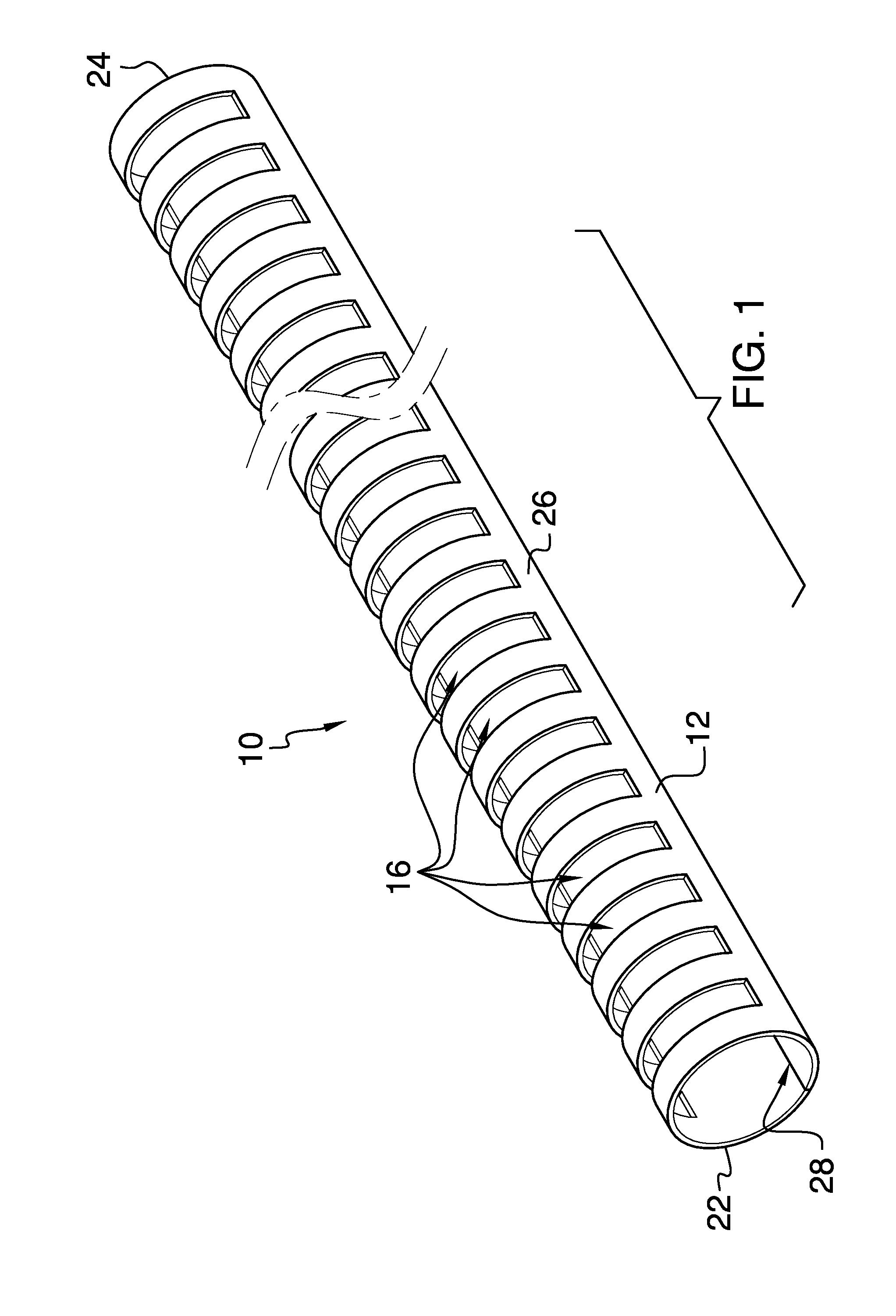
[0011] FIG. 1 is a perspective view of a clothes hanger organization assembly according to an embodiment of the disclosure.
[0012] FIG. 2 is a bottom view of an embodiment of the disclosure.
[0013] FIG. 3 is a front view of an embodiment of the disclosure.
[0014] FIG. 4 is an end view of an embodiment of the disclosure.
[0015] FIG. 5 is a perspective in-use view of an embodiment of the disclosure.
DETAILED DESCRIPTION OF THE INVENTION
[0016] With reference now to the drawings, and in particular to FIGS. 1 through 5 thereof, a new organization device embodying the principles and concepts of an embodiment of the disclosure and generally designated by the reference numeral 10 will be described.
[0017] As best illustrated in FIGS. 1 through 5, the clothes hanger organization assembly 10 generally comprises a sleeve 12 that may be positioned around a closet pole 14. The sleeve 12 has a plurality of slots 16 therein and each of the slots 16 engages a hook 18 on a clothes hanger 20. Moreover, the slots 16 are spaced apart from each other and are distributed along the sleeve 12 to organize a plurality of clothes hangers 20. The sleeve 12 may have a length ranging between approximately 60.0 cm and 180.0 cm.
[0018] The sleeve 12 has a first end 22, a second end 24 and an outer wall 26 extending therebetween. The outer wall 26 has a cut 28 extending between the first end 22 and the second end 24 and the cut 28 has a first edge 30 and a second edge 32. The second edge 32 is selectively urged away from the first end 22 thereby spreading the sleeve 12 apart for positioning around the closet pole 14. Each of the slots 16 extends through the outer wall 26 and each of the slots 16 extends partially around a circumference of the sleeve 12. The slots 16 are spaced apart from each other and are distributed between the first end 22 and the second end 24.
[0019] In use, the first edge 30 of the cut 28 is urged away from the second edge 32 of the cut 28 to spread the sleeve 12 apart. Thus, the sleeve 12 is positioned around the closet pole 14 without having to remove the closet pole 14 from a closet. The hook 18 on each of the hangers is positioned in an associated one of the slots 16. In this way the hangers are neatly arranged on the closet pole 14 and a uniformly spaced apart from each other.
[0020] With respect to the above description then, it is to be realized that the optimum dimensional relationships for the parts of an embodiment enabled by the disclosure, to include variations in size, materials, shape, form, function and manner of operation, assembly and use, are deemed readily apparent and obvious to one skilled in the art, and all equivalent relationships to those illustrated in the drawings and described in the specification are intended to be encompassed by an embodiment of the disclosure.
[0021] Therefore, the foregoing is considered as illustrative only of the principles of the disclosure. Further, since numerous modifications and changes will readily occur to those skilled in the art, it is not desired to limit the disclosure to the exact construction and operation shown and described, and accordingly, all suitable modifications and equivalents may be resorted to, falling within the scope of the disclosure. In this patent document, the word "comprising" is used in its non-limiting sense to mean that items following the word are included, but items not specifically mentioned are not excluded. A reference to an element by the indefinite article "a" does not exclude the possibility that more than one of the element is present, unless the context clearly requires that there be only one of the elements.
* * * * *
D00000
D00001
D00002
D00003
XML
uspto.report is an independent third-party trademark research tool that is not affiliated, endorsed, or sponsored by the United States Patent and Trademark Office (USPTO) or any other governmental organization. The information provided by uspto.report is based on publicly available data at the time of writing and is intended for informational purposes only.
While we strive to provide accurate and up-to-date information, we do not guarantee the accuracy, completeness, reliability, or suitability of the information displayed on this site. The use of this site is at your own risk. Any reliance you place on such information is therefore strictly at your own risk.
All official trademark data, including owner information, should be verified by visiting the official USPTO website at www.uspto.gov. This site is not intended to replace professional legal advice and should not be used as a substitute for consulting with a legal professional who is knowledgeable about trademark law.