Nail Polish Display
Esposito; Michael ; et al.
U.S. patent application number 16/231455 was filed with the patent office on 2019-06-27 for nail polish display. The applicant listed for this patent is Michael Esposito, Richard Barry Shields. Invention is credited to Michael Esposito, Richard Barry Shields.
| Application Number | 20190191851 16/231455 |
| Document ID | / |
| Family ID | 66948781 |
| Filed Date | 2019-06-27 |


| United States Patent Application | 20190191851 |
| Kind Code | A1 |
| Esposito; Michael ; et al. | June 27, 2019 |
Nail Polish Display
Abstract
The nail polish display allows a customer to insert their finger into a slot which is an injection molded unit or tray that has a replaceable printed clear plastic identifier that has the corresponding nail colors on it. The replaceable printed clear plastic identifier can easily be changed when new colors are added or deleted. The injection molded unit or tray is permanent and would be affixed to the store shelf.
| Inventors: | Esposito; Michael; (Newburgh, NY) ; Shields; Richard Barry; (East Setauket, NY) | ||||||||||
| Applicant: |
|
||||||||||
|---|---|---|---|---|---|---|---|---|---|---|---|
| Family ID: | 66948781 | ||||||||||
| Appl. No.: | 16/231455 | ||||||||||
| Filed: | December 22, 2018 |
Related U.S. Patent Documents
| Application Number | Filing Date | Patent Number | ||
|---|---|---|---|---|
| 62609963 | Dec 22, 2017 | |||
| Current U.S. Class: | 1/1 |
| Current CPC Class: | A47F 5/0043 20130101; A45D 29/22 20130101; A47F 7/286 20130101; A45D 44/005 20130101 |
| International Class: | A45D 44/00 20060101 A45D044/00; A45D 29/22 20060101 A45D029/22 |
Claims
1. A nail polish display device, the device comprising: a tray; the tray having one or more recesses creating one or more spaces for the insertion of a fingertip and finger nail; a clear plastic cover; the clear plastic cover removably attached to the tray; and the clear plastic cover overlaid with one or more nail colors.
2. The device of claim 1, wherein the overlaid nail colors correspond to a merchandising offering of corresponding nail polishes.
3. The device of claim 1, wherein the overlaid nail colors on the clear plastic cover are translucent.
4. The device of claim 1, wherein the overlaid nail colors on the clear plastic cover are transparent.
5. The device of claim 2, wherein the printed clear plastic identifier is changed when new colors are added or deleted from the merchandising offering.
6. The device of claim 1, wherein the tray is an injection molded unit.
7. The device of claim 1, wherein the tray is permanent and is affixed to the store shelf.
8. A nail polish display device, the device consisting of: an injection molded tray; the tray has a plurality of semi-cylindrical openings; the tray has two top channels and a ridge for retaining a clear plastic identifier top plate; and a clear plastic identifier or top plate covers the plurality of semi-cylindrical openings allow a shopper to place their fingertip and finger nail inside and against.
9. The nail polish display device of claim 8, wherein tape is used to secure the clear plastic identifier or top plate to the tray.
10. The nail polish display device of claim 8, wherein the size of a tray is 13.73.times.1.65.times.0.75 inches.
11. The nail polish display device of claim 8, wherein the replaceable printed clear plastic identifier is changed when new colors are added or deleted from the display.
12. The nail polish display device of claim 8, wherein the clear plastic identifier top plate is made from a clear plastic with a thickness of approximately 0.100 inches.
13. The nail polish display device of claim 12, wherein the clear plastic identifier top plate is made from clear PETG.
14. The nail polish display device of claim 12, wherein the size of the clear plastic identifier top plate of a desired display is 12.97.times.1.41.times.0.50 inches.
15. The nail polish display device of claim 12, wherein the clear plastic identifier or top plate can be covered with a transparent or translucent film matching the colors of corresponding nail polishes and product that are being offered for sale.
16. The nail polish display device of claim 15, wherein the replaceable printed clear plastic identifier or top plate is changed when new colors are added or deleted.
17. The nail polish display device of claim 8, wherein the tray further consists of a plurality of top channels and at least one ridge; the clear plastic identifier or top plate further consists of a lip and a plurality of supporting arms; the lip corresponds to the two top channels and ridge of the tray; and the lip fits over and engages the ridge, while the supporting arms of the lip match up and are retained between the top channels of the tray.
18. The nail polish display device of claim 17, wherein the two channels, corresponding arms, and the ridge and lip are constructed of similar size so that when combined they have a tight fit with respect to the interlocking and interconnecting features of each, which secures the clear plastic identifier or top plate to the tray using compression forces.
19. The nail polish display device of claim 18, wherein tape is used to secure the clear plastic identifier or top plate to the tray.
Description
SEQUENCE LISTING OR PROGRAM
[0001] Not Applicable
TECHNICAL FIELD OF THE INVENTION
[0002] The present invention relates generally to merchandising display. More specifically, the present invention relates to nail polish display.
BACKGROUND OF THE INVENTION
[0003] For women and girls, painting their nails is a game of chance. During the shopping experience there are numerous issues to determine, such as: Will the color look like it does in the bottle? Will you like the way it looks against your skin? Will you even be able to tell once half your finger is covered in polish, because it's like impossible to paint inside the lines?
[0004] They typical current approach by shoppers includes opening the bottles and trying them which the stores do not like as it results in unsellable product. Other approaches consist of shopper holding the bottle up to their hand and then replacing the bottle sometimes in the wrong area which the stores do not like as it results in a disorganized and messy/sloppy appearing display.
[0005] Many times, while shopping, a buyer will see a color they like, which later looks horrible with outfits or their skin tone. Mobile applications have been developed, but they fail during actual shopping experiences in physical stores and are clumsy to use. Providing actual examples for literal rainbow of color selections results in a large amount of wasted product, expense, and mess.
[0006] What is needed is a physical display system that allows a user, during an in-store shopping experience, to see just how a given nail polish will look on their nail, against their own skin, without wasting product, being messy, and adding additional expense.
[0007] Accordingly, a need exists for an apparatus that is capable of displaying a variety of different sized packaging for merchandise where the sampling and comparison of the product is simplified, quicker, and easier.
Definitions
[0008] Injection molding is a manufacturing process for producing parts by injecting material into a mold. Injection molding can be performed with a host of materials mainly including metals, (for which the process is called die-casting), glasses, elastomers, confections, and most commonly thermoplastic and thermosetting polymers. Material for the part is fed into a heated barrel, mixed, and forced into a mold cavity, where it cools and hardens to the configuration of the cavity. After a product is designed, usually by an industrial designer or an engineer, molds are made by a mold-maker (or toolmaker) from metal, usually either steel or aluminum, and precision-machined to form the features of the desired part. Injection molding is widely used for manufacturing a variety of parts, from the smallest components to entire body panels of cars. Advances in 3D printing technology, using photopolymers which do not melt during the injection molding of some lower temperature thermoplastics, can be used for some simple injection molds.
[0009] Parts to be injection molded must be very carefully designed to facilitate the molding process; the material used for the part, the desired shape and features of the part, the material of the mold, and the properties of the molding machine must all be taken into account. The versatility of injection molding is facilitated by this breadth of design considerations and possibilities. Thermoforming is a generic term for the manufacturing of plastic components through the vacuum and/or pressure forming processes. A simplistic overview of the single-sheet thermoforming process consists of heating an extruded sheet of plastic and either forming the sheet over a male mold or into a female mold. Depending on what type of mold a customer selects, the thermoforming process allows the customer the ability to receive a part with the same aesthetic properties as an injection-molded part at a fraction of the tooling expense involved in injection molding.
[0010] Polyethylene terephthalate (aka. PET, PETE, PETG) is a plastic resin of the polyester family that is used to make beverage, food and other liquid containers, as well as for some other thermoforming applications. PETG is a clear amorphous thermoplastic that can be injection molded or sheet extruded. It can be colored during processing.
[0011] Vacuum forming is a simplified version of thermoforming, whereby a sheet of plastic is heated to a forming temperature, stretched onto a single-surface mold, and forced against the mold by a vacuum is formed into permanent objects such as turnpike signs and protective covers.
SUMMARY OF THE INVENTION
[0012] The device of the present invention is a nail polish display that allows a customer to insert their finger into a slot which is an injection molded unit or tray that has a replaceable printed clear plastic identifier that has the corresponding nail colors on it. The replaceable printed clear plastic identifier can easily be changed when new colors are added or deleted. The injection molded unit or tray is permanent and would be affixed to the store shelf.
BRIEF DESCRIPTION OF THE DRAWINGS
[0013] The accompanying drawings, which are incorporated herein and form a part of the specification, illustrate the present invention and, together with the description, further serve to explain the principles of the invention and to enable a person skilled in the pertinent art to make and use the invention.
[0014] FIG. 1 illustrates a perspective view of the tray of the present invention.
[0015] FIG. 2 illustrates a perspective view of the top plate or replaceable printed clear plastic identifier of the present invention.
[0016] FIG. 3 illustrates a side planar view of the tray of the present invention.
[0017] FIG. 4 illustrates a top planar view of the tray of the present invention.
[0018] FIG. 5 illustrates a top planar view of the top plate or replaceable printed clear plastic identifier of the present invention.
[0019] FIG. 6 illustrates a side planar view of the top plate or replaceable printed clear plastic identifier of the present invention.
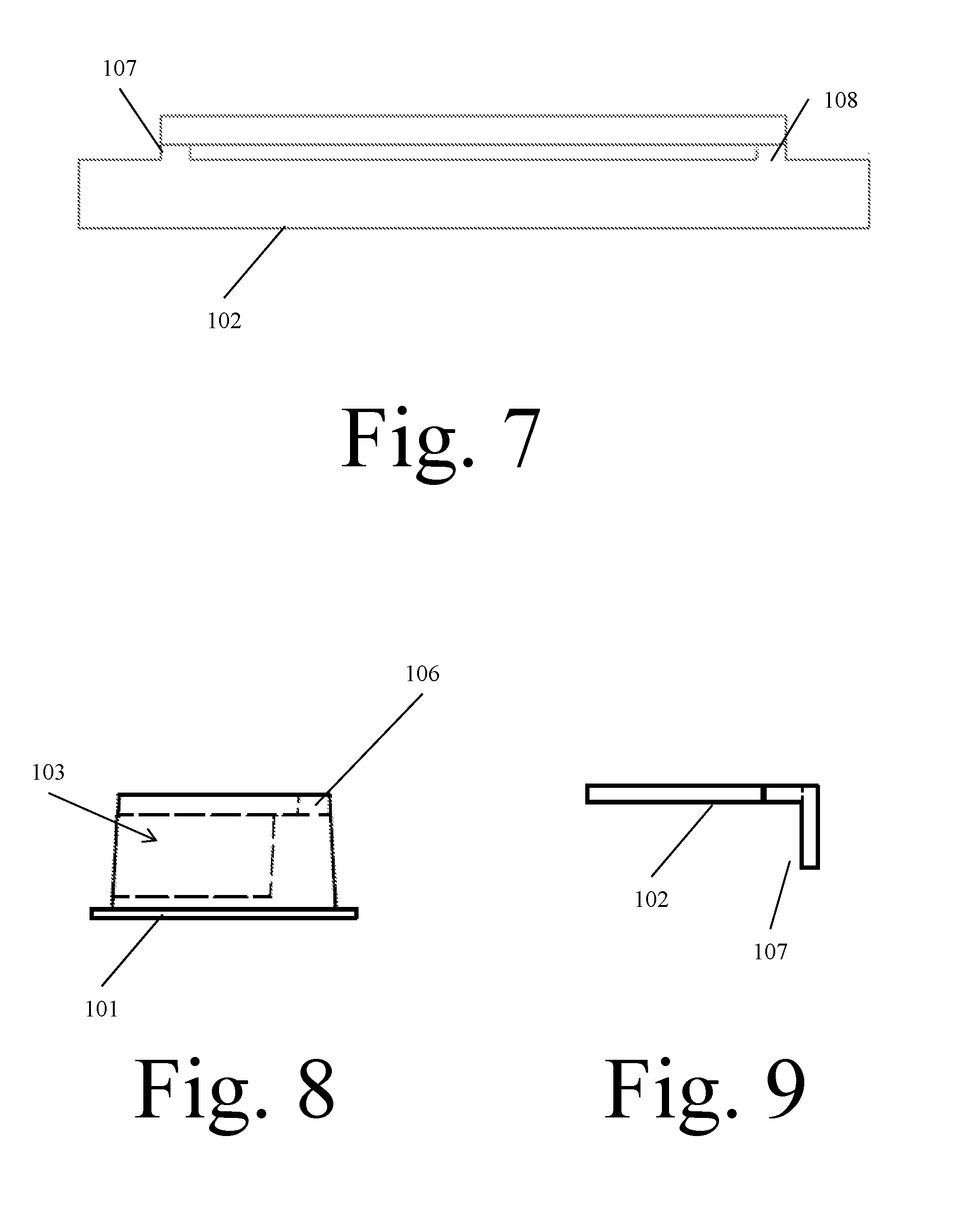
[0020] FIG. 7 illustrates a top planar view of the top plate or replaceable printed clear plastic identifier of the present invention.
[0021] FIG. 8 illustrates a side planar view of the tray of the present invention.
[0022] FIG. 9 illustrates a side planar view of the top plate of the present invention.
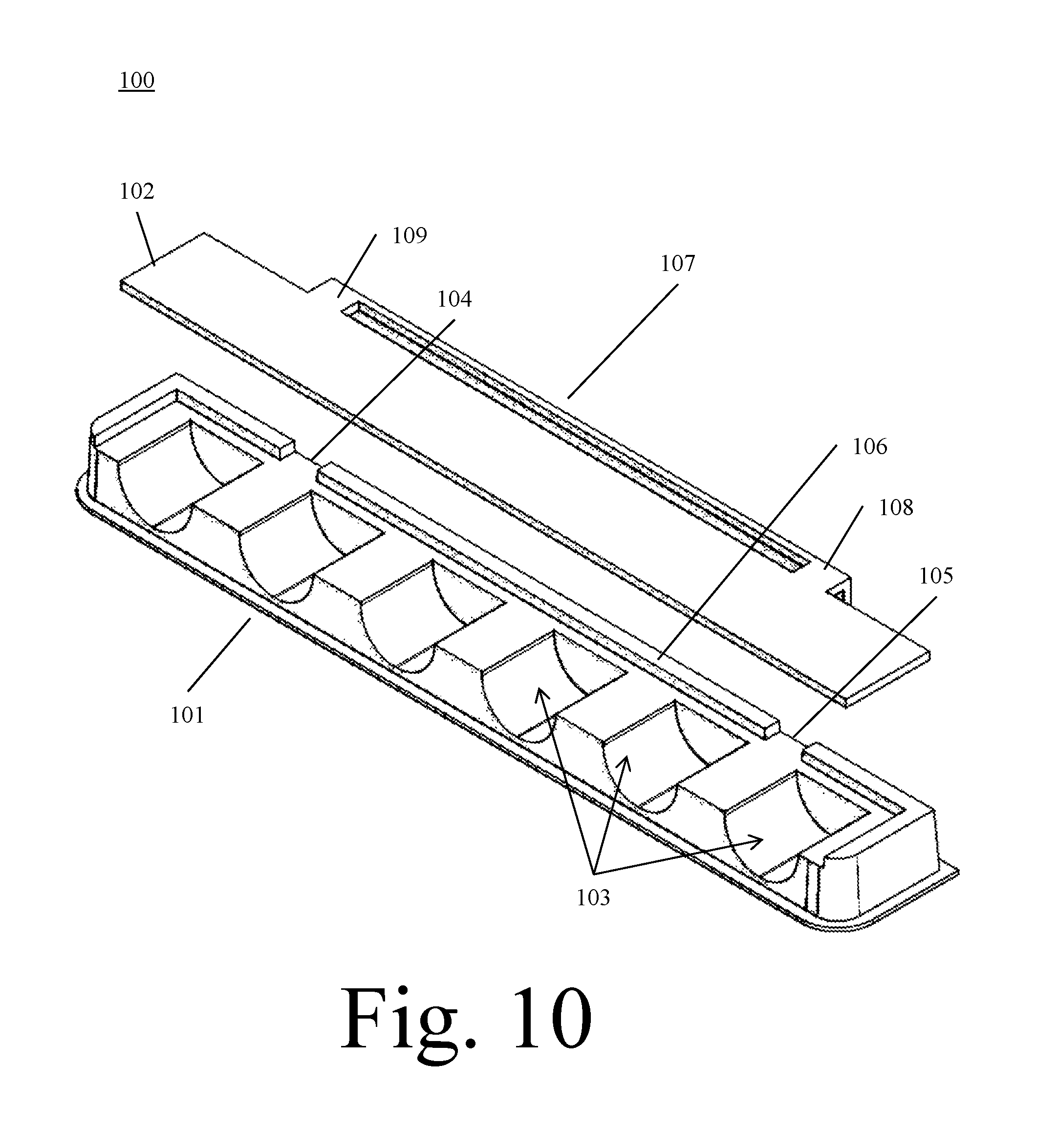
[0023] FIG. 10 illustrates a front perspective view of the tray and the top plate or replaceable printed clear plastic identifier of the present invention.
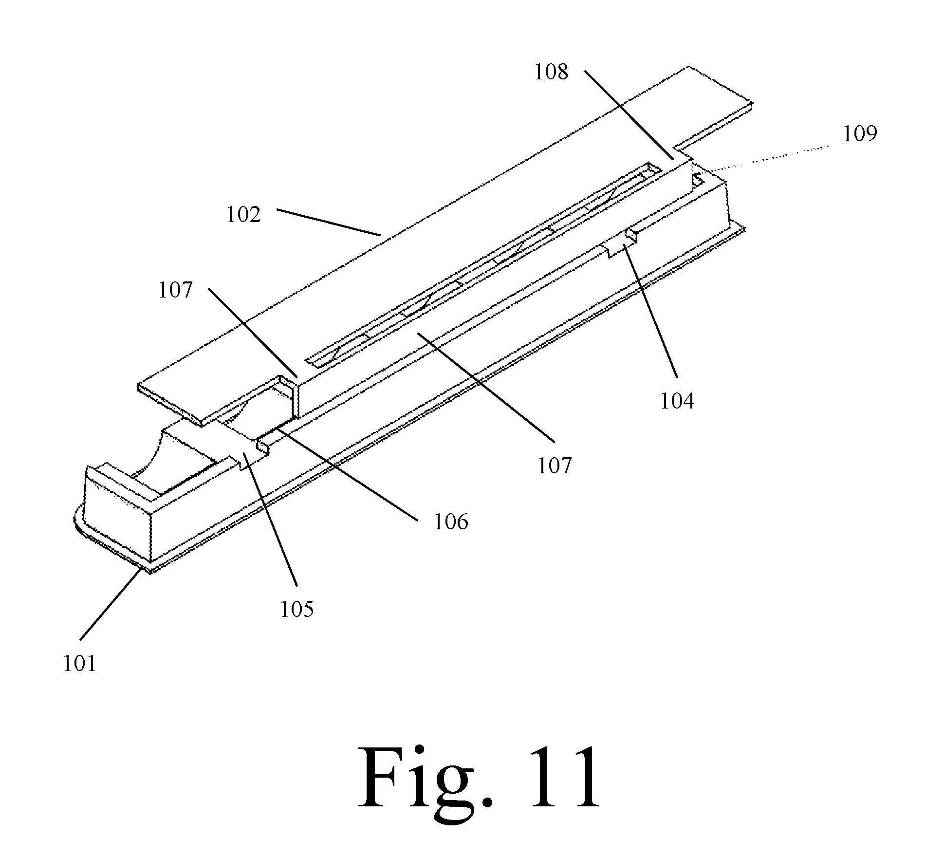
[0024] FIG. 11 illustrates a rear perspective view of the tray and the top plate or replaceable printed clear plastic identifier of the present invention.
DETAILED DESCRIPTION OF THE INVENTION
[0025] In the following detailed description of the invention of exemplary embodiments of the invention, reference is made to the accompanying drawings (where like numbers represent like elements), which form a part hereof, and in which is shown by way of illustration specific exemplary embodiments in which the invention may be practiced. These embodiments are described in sufficient detail to enable those skilled in the art to practice the invention, but other embodiments may be utilized and logical, mechanical, electrical, and other changes may be made without departing from the scope of the present invention. The following detailed description is, therefore, not to be taken in a limiting sense, and the scope of the present invention is defined only by the appended claims.
[0026] In the following description, numerous specific details are set forth to provide a thorough understanding of the invention. However, it is understood that the invention may be practiced without these specific details. In other instances, well-known structures and techniques known to one of ordinary skill in the art have not been shown in detail in order not to obscure the invention. Referring to the figures, it is possible to see the various major elements constituting the apparatus of the present invention.
[0027] The device of the present invention is a nail polish display 100 that solves the problem women have going into a store to buy nail polish and find it difficult to decide which color looks best on their nails. The current approach includes opening the bottles and trying them which the stores do not like. Other approaches consist of shopper holding the bottle up to their hand and then replacing the bottle sometimes in the wrong area.
[0028] The device of the present invention solves all of that by allowing the customer to insert their finger into the slot which is an injection molded unit or tray 101 that has a replaceable printed clear plastic identifier 102 that has the corresponding nail colors on it. A replaceable printed clear plastic identifier 102 can easily be changed when new colors are added or deleted. The injection molded unit or tray 101 is permanent and would be affixed to the store shelf.
[0029] Now referring to FIGS. 1-4, the injection molded tray 101 is illustrated. The tray 101 has a plurality of semi-cylindrical openings 103 that allow a shopper to place their fingertip and finger nail inside and against. The tray 101 also has two top channels 104 and 105 and a ridge 106 for retaining a clear plastic identifier 102 top plate. The approximate size of a tray of a desired display is 13.73.times.1.65.times.0.75 inches.
[0030] FIGS. 3-5 illustrate the replaceable printed clear plastic identifier 102 that can easily be changed when new colors are added or deleted. This clear plastic identifier 102 or top plate covers the plurality of semi-cylindrical openings 103 that allow a shopper to place their fingertip and finger nail inside and against. The clear plastic identifier 102 top plate is made from a clear plastic with a thickness of approximately 0.100 inches and is ideally made from clear PETG. The approximate size of a clear plastic identifier 102 top plate of a desired display is 12.97.times.1.41.times.0.50 inches.
[0031] The clear plastic identifier 102 or top plate can be covered with a transparent or translucent film matching the colors of corresponding nail polishes and product that are being offered for sale. The replaceable printed clear plastic identifier 102 or top plate that can easily be changed when new colors are added or deleted.
[0032] As shown in FIGS. 10-11, the clear plastic identifier 102 or top plate is also comprised of a lip 107, which corresponds to the two top channels 104 and 105 and ridge 106 of the tray 101. The lip 107 fits over and engages the ridge 106, while the supporting arms 108 and 109 of the lip 107 match up and are retained between the two top channels 104 and 105 of the tray 101, which secures the clear plastic identifier 102 or top plate to the tray 101 using compression forces as the two channels 104 and 105, corresponding arms 108 and the ridge 106 and lip 107 are constructed of similar size so that when combined they have a tight fit with respect to the interlocking and interconnecting features of each. Tape 109 can also be used to secure the clear plastic identifier 102 or top plate to the tray 101 as shown in FIG. 11.
[0033] Thus, it is appreciated that the optimum dimensional relationships for the parts of the invention, to include variation in size, materials, shape, form, function, and manner of operation, assembly and use, are deemed readily apparent and obvious to one of ordinary skill in the art, and all equivalent relationships to those illustrated in the drawings and described in the above description are intended to be encompassed by the present invention.
[0034] Furthermore, other areas of art may benefit from this method and adjustments to the design are anticipated. Thus, the scope of the invention should be determined by the appended claims and their legal equivalents, rather than by the examples given.
* * * * *
D00000
D00001
D00002
D00003
D00004
D00005
D00006
XML
uspto.report is an independent third-party trademark research tool that is not affiliated, endorsed, or sponsored by the United States Patent and Trademark Office (USPTO) or any other governmental organization. The information provided by uspto.report is based on publicly available data at the time of writing and is intended for informational purposes only.
While we strive to provide accurate and up-to-date information, we do not guarantee the accuracy, completeness, reliability, or suitability of the information displayed on this site. The use of this site is at your own risk. Any reliance you place on such information is therefore strictly at your own risk.
All official trademark data, including owner information, should be verified by visiting the official USPTO website at www.uspto.gov. This site is not intended to replace professional legal advice and should not be used as a substitute for consulting with a legal professional who is knowledgeable about trademark law.