Bottle Closure Assembly Including A Polyethylene Copolymer
Wang; XiaoChuan ; et al.
U.S. patent application number 16/220571 was filed with the patent office on 2019-06-20 for bottle closure assembly including a polyethylene copolymer. This patent application is currently assigned to NOVA Chemicals (International) S.A.. The applicant listed for this patent is NOVA Chemicals (International) S.A.. Invention is credited to Cliff Baar, Ian Gibbons, Amin Mirzadeh, Eric Vignola, XiaoChuan Wang.
| Application Number | 20190185219 16/220571 |
| Document ID | / |
| Family ID | 65199439 |
| Filed Date | 2019-06-20 |


View All Diagrams
| United States Patent Application | 20190185219 |
| Kind Code | A1 |
| Wang; XiaoChuan ; et al. | June 20, 2019 |
BOTTLE CLOSURE ASSEMBLY INCLUDING A POLYETHYLENE COPOLYMER
Abstract
The present disclosure describes bottle closure assemblies which are made at least in part with a polyethylene copolymer having good organoleptic properties. The bottle closure assembly includes a cap portion, an elongated tether portion, and a retaining means portion. The retaining means portions engages a bottle neck or an upper portion of a bottle. The elongated tether portion connects at least one point on the cap portion to at least one point on the retaining means portion so as to prevent loss of the cap portion from a bottle.
| Inventors: | Wang; XiaoChuan; (Calgary, CA) ; Gibbons; Ian; (Calgary, CA) ; Vignola; Eric; (Airdrie, CA) ; Baar; Cliff; (Calgary, CA) ; Mirzadeh; Amin; (Calgary, CA) | ||||||||||
| Applicant: |
|
||||||||||
|---|---|---|---|---|---|---|---|---|---|---|---|
| Assignee: | NOVA Chemicals (International)
S.A. Fribourg CH |
||||||||||
| Family ID: | 65199439 | ||||||||||
| Appl. No.: | 16/220571 | ||||||||||
| Filed: | December 14, 2018 |
Related U.S. Patent Documents
| Application Number | Filing Date | Patent Number | ||
|---|---|---|---|---|
| 62607610 | Dec 19, 2017 | |||
| Current U.S. Class: | 1/1 |
| Current CPC Class: | B65D 55/16 20130101; B29K 2023/065 20130101; B65D 2543/00296 20130101; B29K 2105/0094 20130101; B65D 41/34 20130101; B65D 2543/00537 20130101; B29L 2031/56 20130101; B65D 41/3428 20130101 |
| International Class: | B65D 41/34 20060101 B65D041/34 |
Claims
1. A bottle closure assembly comprising: a cap portion, a tether portion, and a retaining means portion, the cap portion being molded to reversibly engage and cover a bottle opening, the retaining means portion being molded to irreversibly engage a bottle neck or an upper portion of a bottle, and wherein the tether portion connects at least one point on the cap portion to at least one point on the retaining means portion, wherein the cap portion, optionally the tether portion, and optionally the retaining means portion are made from a polyethylene copolymer having a density of from 0.940 to 0.962 g/cm.sup.3, a melt index 12 of less than 1.5 g/10 min, an amount of terminal unsaturation of at least 0.45 per 1000 carbon atoms, fewer than 0.9 parts per million of titanium, and fewer than 0.4 parts per million of chromium.
2. A bottle closure assembly comprising: a cap portion, an elongated tether portion, and a retaining means portion, the cap portion being molded to reversibly engage and cover a bottle opening, the retaining means portion being molded to irreversibly engage a bottle neck or an upper portion of a bottle, and the elongated tether portion being molded to connect at least one point on the cap portion to at least one point on the retaining means portion, wherein the cap portion, optionally the elongated tether portion, and optionally the retaining means portion are made from a polyethylene copolymer having a density of from 0.940 to 0.962 g/cm.sup.3, a melt index 12 of less than 1.5 g/10 min, an amount of terminal unsaturation of at least 0.45 per 1000 carbon atoms, fewer than 0.9 parts per million of titanium, and fewer than 0.4 parts per million of chromium.
3. A bottle closure assembly comprising: an integrally molded: cap portion, tether portion, and retaining means portion; the cap portion being molded to reversibly engage and cover a bottle opening, the retaining means portion being molded to irreversibly engage a bottle neck or an upper portion of a bottle, and the tether portion being molded to connect at least one point on the cap portion to at least one point on the retaining means portion; wherein the integrally molded: cap portion, tether portion, and retaining means portion are made from a polyethylene copolymer which has a density of from 0.940 to 0.962 g/cm.sup.3, a melt index 12 of less than 1.5 g/10 min, an amount of terminal unsaturation of at least 0.45 per 1000 carbon atoms, fewer than 0.9 parts per million of titanium, and fewer than 0.4 parts per million of chromium.
4. A bottle closure assembly comprising: an integrally molded: cap portion, elongated tether portion, and retaining means portion; the cap portion being molded to reversibly engage and cover a bottle opening, the retaining means portion being molded to irreversibly engage a bottle neck or an upper portion of a bottle, and the elongated tether portion being molded to connect at least one point on the cap portion to at least one point on the retaining means portion; wherein the integrally molded: cap portion, elongated tether portion, and retaining means portion are made from a polyethylene copolymer which has a density of from 0.940 to 0.962 g/cm.sup.3, a melt index 12 of less than 1.5 g/10 min, an amount of terminal unsaturation of at least 0.45 per 1000 carbon atoms, fewer than 0.9 parts per million of titanium, and fewer than 0.4 parts per million of chromium.
5. A bottle closure assembly comprising: an integrally molded: cap portion, elongated tether portion, and retaining collar portion; the cap portion being molded to reversibly engage and cover a bottle opening, the retaining collar portion being molded to irreversibly engage a bottle neck or an upper portion of a bottle, and the elongated tether portion being molded to connect at least one point on the cap portion to at least one point on the retaining collar portion; wherein the integrally molded: cap portion, elongated tether portion, and retaining collar portion are made from a polyethylene copolymer which has a density of from 0.940 to 0.962 g/cm.sup.3, a melt index 12 of less than 1.5 g/10 min, an amount of terminal unsaturation of at least 0.45 per 1000 carbon atoms, fewer than 0.9 parts per million of titanium, and fewer than 0.4 parts per million of chromium.
6. A bottle closure assembly comprising: a closure portion, an elongated tether portion, and a retaining collar portion, the closure portion being molded to reversibly engage and cover a bottle opening, the elongated tether portion comprising a tether strip which is frangibly connected along a portion of its upper edge to a descending annular edge of the closure portion and which is frangibly connected along a portion of its lower edge to an upper annular edge of the retaining collar portion, the tether strip being integrally formed with and connected at one end to at least one point on the closure portion and integrally formed with and connected at another end to at least one point on the retaining collar portion, the frangible sections being breakable when the closure portion is removed from a bottle opening, but where the closure portion remains connected to the retaining collar via the tether strip; wherein the cap portion, the elongated tether portion, and the retaining collar portion are integrally molded from a polyethylene copolymer which has a density of from 0.940 to 0.962 g/cm.sup.3, a melt index 12 of less than 1.5 g/10 min, an amount of terminal unsaturation of at least 0.45 per 1000 carbon atoms, fewer than 0.9 parts per million of titanium, and fewer than 0.4 parts per million of chromium.
Description
CROSS REFERENCE TO RELATED APPLICATIONS
[0001] This application claims the benefit of the filing date of U.S. Provisional Application No. 62/607,610, which was filed on Dec. 19, 2017. The contents of U.S. Provisional Application No. 62/607,610 are incorporated herein by reference in their entirety.
TECHNICAL FIELD
[0002] The present disclosure is directed to bottle closure assemblies which are made at least in part with a polyethylene copolymer. The bottle closure assembly includes a cap portion, a tether portion, and a retaining means portion.
BACKGROUND
[0003] The manufacture of simple one-piece closures using polyethylene compositions is well known to persons skilled in the art.
[0004] Bottle closure systems and designs incorporating an integrated tethering means, which secures a cap portion to a bottle after the cap
[0005] has been removed from a bottle opening are also well known. Such designs typically involve molding processes which present a more complicated and longer flow path for a chosen plastic material relative to simple one-piece closure designs. As such, it would be beneficial to make tethered closure systems using a thermoplastic material which shows good performance in molding applications, especially those which involve longer and more tortuous flow paths in a mold. It would also be advantageous to make a tethered closure system using a material that has sufficient stress crack resistance and flexibility, as the tethering portion would need to be both strong enough to prevent loss of the cap portion once it has been removed from a bottle opening, and flexible enough to allow the tethering portion to be formed or bent into suitable closure system designs.
SUMMARY
[0006] The present disclosure concerns bottle closure assemblies including a cap portion, a tether portion, and a retaining means portion. The bottle closure assembly can be made at least in part from a polyethylene copolymer having good organoleptic properties.
[0007] An embodiment of the present disclosure provides a bottle closure assembly which includes a cap portion, a tether portion, and a retaining means portion, the bottle closure assembly being made at least in part from a polyethylene copolymer which has a density of from 0.940 to 0.962 g/cm.sup.3, a melt index 12 of less than 1.5 g/10 min, an amount of terminal unsaturation of at least 0.45 per 1000 carbon atoms, fewer than 0.9 parts per million of titanium, and fewer than 0.4 parts per million of chromium.
BRIEF DESCRIPTION OF THE DRAWINGS
[0008] FIG. 1A shows an embodiment of a bottle closure assembly fitted to a bottle opening and in a "closed" or "sealed" position. FIG. 1B shows an embodiment of a bottle closure assembly as a cap portion is rotated in order to bring about its removal from a bottle opening. FIG. 1C shows an embodiment of a bottle closure assembly after a cap portion has been removed from a bottle opening. FIG. 1C shows how an elongated tether portion connects at least one point on a cap portion to at least one point on a retaining collar portion once a cap portion has been removed from a bottle opening.
[0009] FIG. 2A shows an embodiment of a bottle closure assembly fitted over a bottle opening and before a cap portion has been removed from a bottle. FIG. 2B shows an embodiment of a bottle closure assembly after a cap portion has been removed from a bottle opening. FIG. 2B also shows how an elongated tether portion connects at least one point on a cap portion to at least one point on a retaining collar portion once a cap portion has been removed from a bottle opening, thereby preventing its loss.
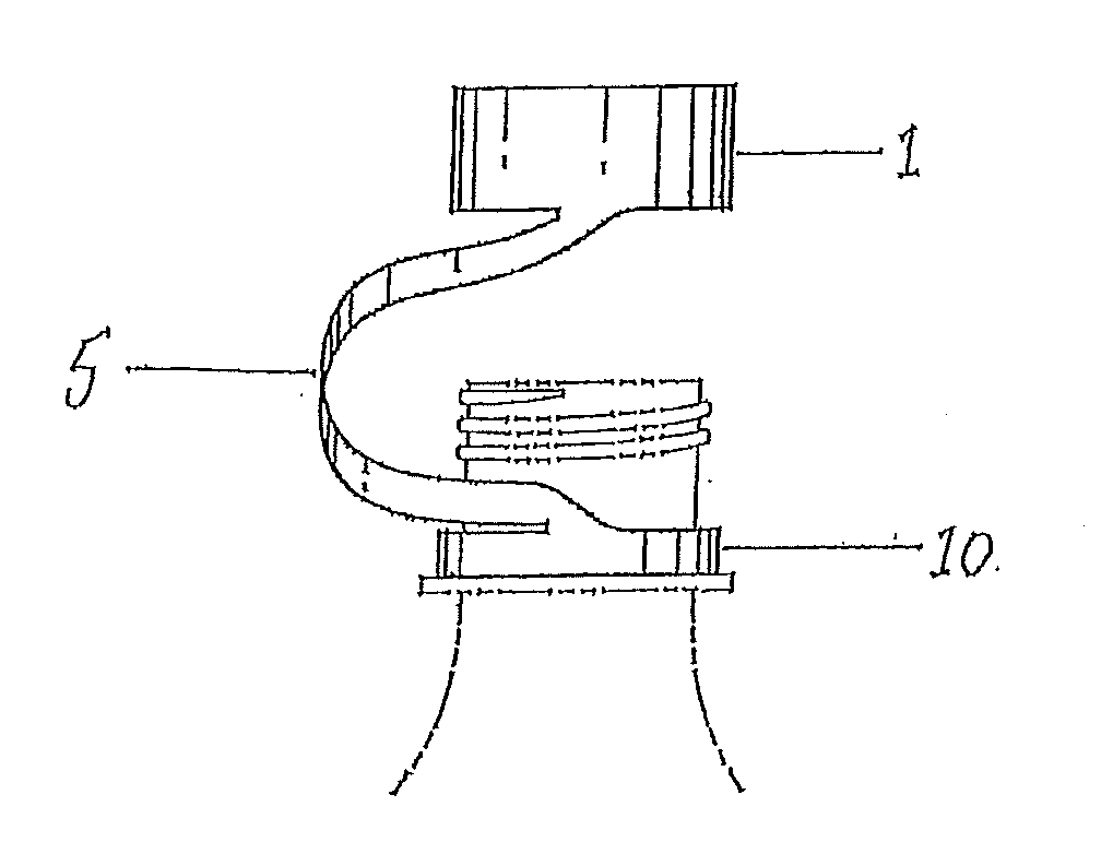
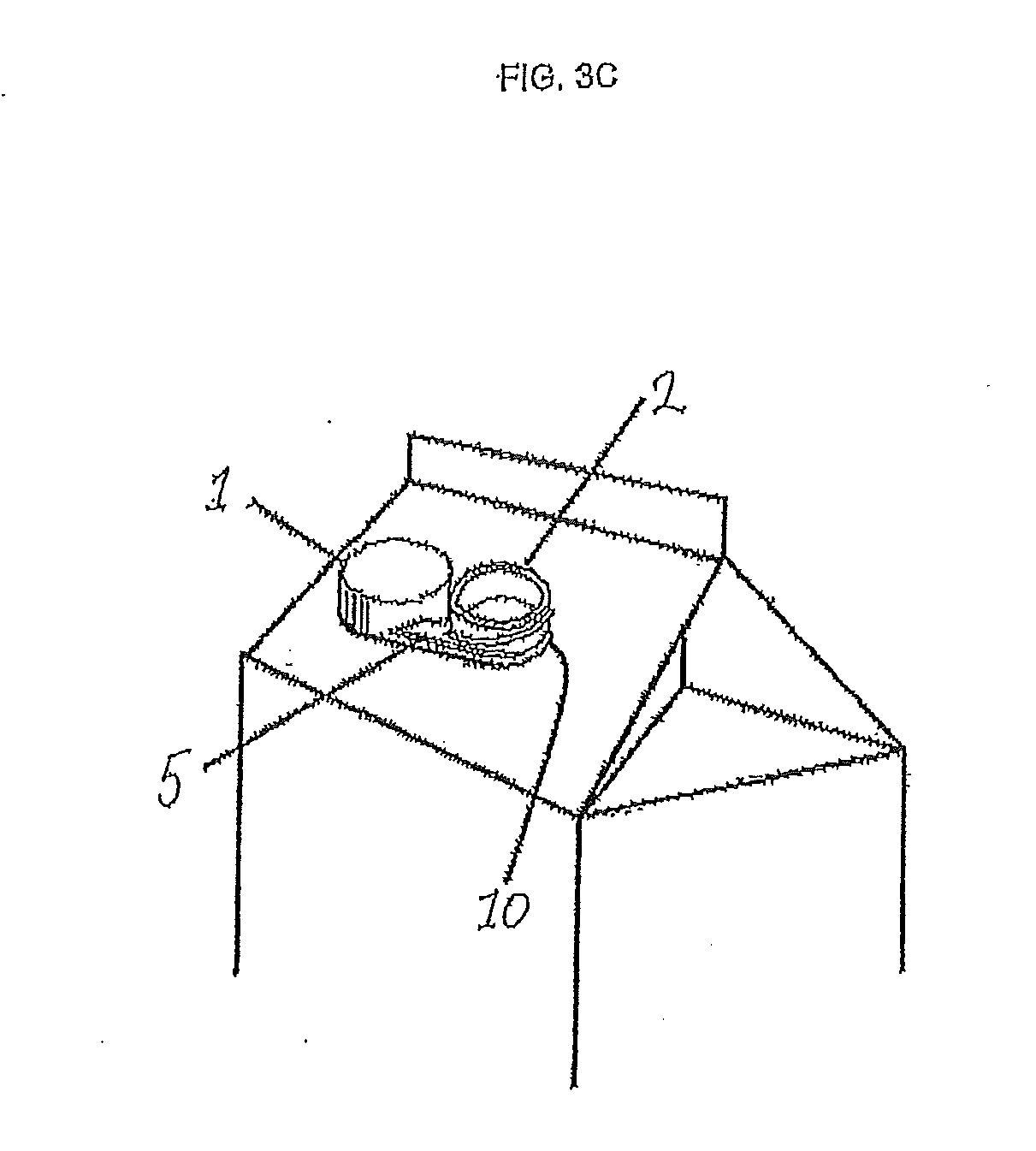
[0010] FIG. 3A shows an embodiment of a bottle closure assembly. FIG. 3B shows an embodiment of a bottle closure assembly after a cap portion has been removed from a bottle opening. FIG. 3B also shows how an elongated tether portion connects at least one point on a cap portion to at least one point on a retaining collar portion once a cap portion has been removed from a bottle opening, thereby preventing its loss. FIG. 3C shows how an elongated tether portion connects at least one point on a cap portion to at least one point on a retaining collar portion once a cap portion has been removed from a bottle opening. FIG. 3C further shows that a bottle can be a carton, a container, or any other suitable containment vessel which has or is fitted with an aperture or opening which can be covered or sealed using a bottle closure assembly.
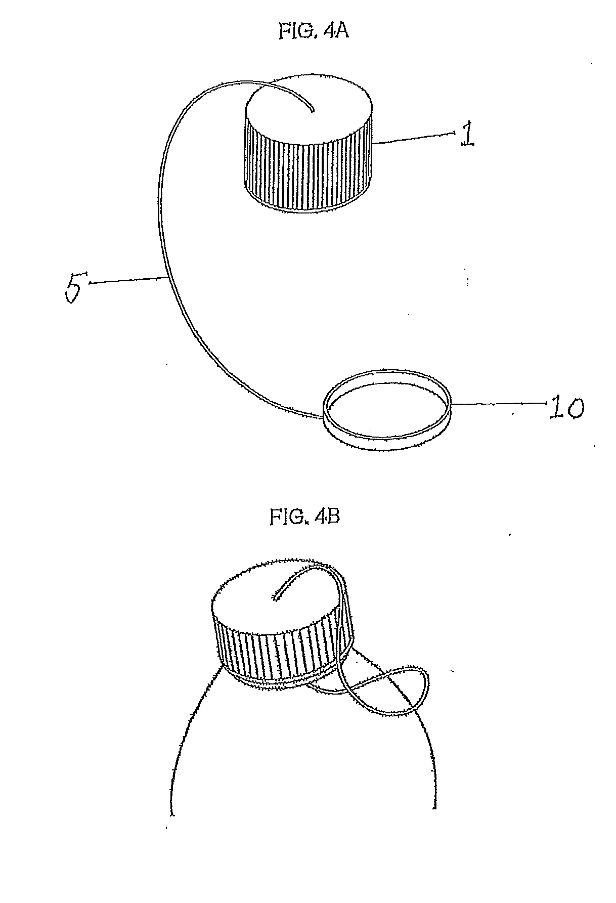
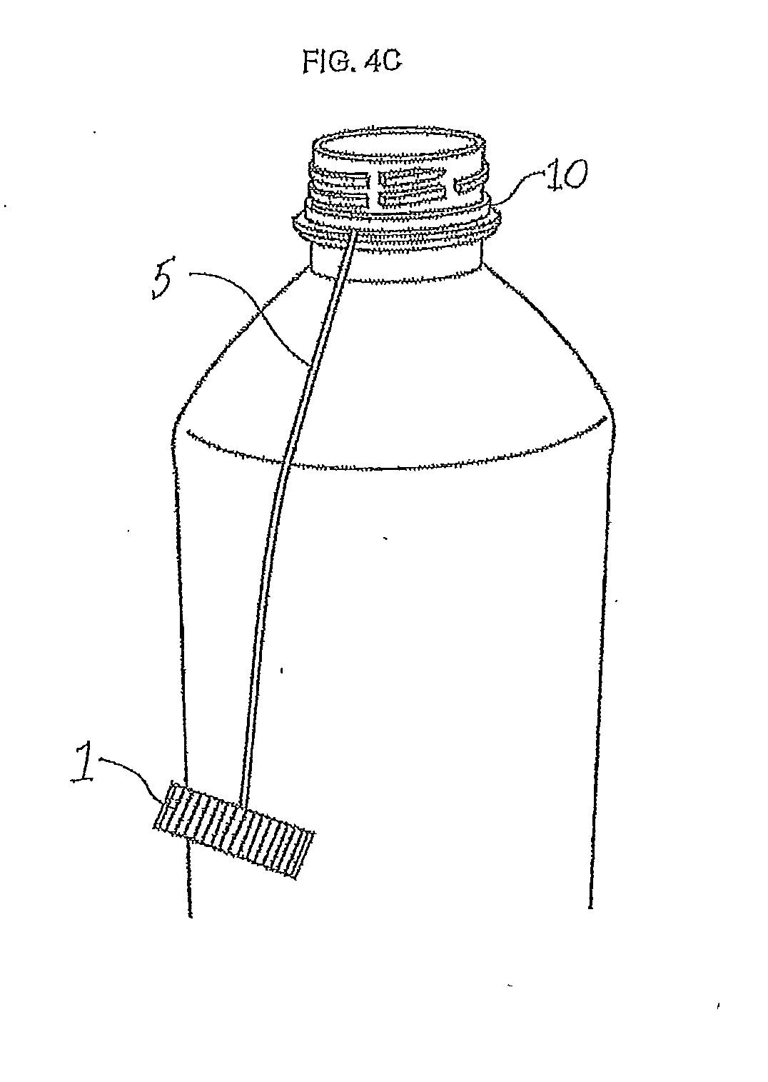
[0011] FIG. 4A shows an embodiment of a bottle closure assembly in the absence of a bottle. The bottle closure assembly has a cap portion, an elongated tether portion, and a retaining collar portion. FIG. 4B shows an embodiment of a bottle closure assembly fitted over a bottle opening and before a cap portion has been removed from a bottle opening. FIG. 4C shows an embodiment of a bottle closure assembly after a cap portion has been removed from a bottle opening.
[0012] FIG. 5A shows an embodiment of a bottle closure assembly in the absence of a bottle. FIG. 5B shows an embodiment of a bottle closure assembly as a cap portion is rotated in order to bring about its removal from a bottle opening.
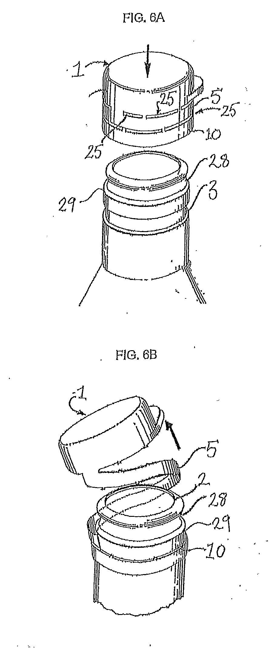
[0013] FIG. 6A shows an embodiment of a bottle closure assembly which fits over a bottle opening. FIG. 6B show an embodiment of a bottle closure assembly after a cap portion has been removed from a bottle opening. FIG. 6B shows how an elongated tether portion connects at least one point on a cap portion to at least one point on a retaining collar portion once a cap portion has been removed from a bottle opening.
[0014] FIG. 7A shows an embodiment of a bottle closure assembly fitted to a bottle opening and in a "closed" or "sealed" position. FIG. 7B shows an embodiment of a bottle closure assembly after a cap portion has been removed from a bottle opening. FIG. 7B shows how an elongated tether portion connects at least one point on a cap portion to at least one point on a retaining collar portion once a cap portion has been removed from a bottle opening.
[0015] FIG. 8 shows a gel permeation chromatograph of the polymer used in Example 3.
[0016] FIG. 9 shows a gel permeation chromatograph of the polymer used in Example 4.
[0017] FIG. 10A shows a perspective view of a closure having a tether proxy. FIG. 10B shows a front elevation view of a closure having a tether proxy. In FIGS. 10A and 10B a tether proxy connects a cap portion to a tamper evident band.
[0018] FIG. 11A shows a perspective view of a closure having a tether proxy after much of the tamper evident band has been removed. In FIG. 11A a tether proxy connects a cap portion to the remaining section of the tamper evident band.
[0019] FIG. 11B shows a front elevation partial cross-sectional schematic view of a closure having a tether proxy and being mounted on a pre-form for shear deformation testing. Prior to mounting the closure on the pre-form, much of the tamper evident band was removed. The tether proxy connects a cap portion to the remaining section of the tamper evident band. To measure shear deformation of the tether proxy, the remaining section of the tamper evident band is clamped in a stationary position to the pre-form, while the cap portion is rotated within a torque tester, as shown.
[0020] FIG. 11C shows a side elevation partial cross-sectional schematic view of a closure having a tether proxy and being mounted on a pre-form for tear deformation testing. The tamper evident band was deflected down and away from the cap portion, while leaving the tether proxy intact. The tether proxy connects the cap portion to the downwardly deflected tamper evident band. To measure tear deformation of the tether proxy, the downwardly deflected tamper evident band is clamped in a stationary position to the pre-form, while the cap portion is rotated within a torque tester, as shown.
[0021] FIGS. 12A and 12B show a perspective view and a front elevation view respectively, of a tether proxy after much of the cap portion and much of the tamper evident band have been removed. To measure tensile deformation of the tether proxy, the remaining section of the cap portion and the remaining section of the tamper evident band are each clamped and then drawn apart in a vertical direction, within a tensile tester, as shown.
DETAILED DESCRIPTION OF THE DISCLOSURE
[0022] Any suitable bottle closure assembly design including a cap portion or a closure portion, a tether portion, and a retaining means portion is contemplated for use in the present disclosure, so long as it is made at least in part using a polyethylene copolymer as described herein. However, some specific non-limiting examples of suitable bottle closure assemblies for use in the present disclosure are disclosed in U.S. Pat. Nos. 3,904,062; 4,474,302; 4,557,393; 4,564,114; 4,573,602; 4,583,652; 4,805,792; 5,725,115; 8,443,994; 8,720,716; 9,493,283; and 9,776,779; U.S. Patent Application Publication Nos. 2004/0016715 and 2008/0197135; U.S. Design Pat. No. D593,856; and WO 2015/061834; all of which are incorporated herein by reference. For further reference, some bottle closure assembly designs which may be used in embodiments of the present disclosure are shown in FIGS. 1-7.
[0023] An embodiment of the disclosure is a bottle closure assembly including: a cap portion, a tether portion, and a retaining means portion, the cap portion being molded to reversibly engage and cover a bottle opening, the retaining means portion being molded to irreversibly engage a bottle neck or an upper portion of a bottle, and where the tether portion connects at least one point on the cap portion to at least one point on the retaining means portion, wherein the cap portion, optionally the tether portion, and optionally the retaining means portion are made from a polyethylene copolymer which has a density of from 0.940 to 0.962 g/cm.sup.3, a melt index 12 of less than 1.5 g/10 min, an amount of terminal unsaturation of at least 0.45 per 1000 carbon atoms, fewer than 0.9 parts per million of titanium, and fewer than 0.4 parts per million of chromium.
[0024] An embodiment of the disclosure is a bottle closure assembly including: a cap portion, an elongated tether portion, and a retaining means portion, the cap portion being molded to reversibly engage and cover a bottle opening, the retaining means portion being molded to irreversibly engage a bottle neck or an upper portion of a bottle, and the elongated tether portion being molded to connect at least one point on the cap portion to at least one point on the retaining means portion, wherein the cap portion, optionally the elongated tether portion, and optionally the retaining means portion are made from a polyethylene copolymer which has a density of from 0.940 to 0.962 g/cm.sup.3, a melt index 12 of less than 1.5 g/10 min, an amount of terminal unsaturation of at least 0.45 per 1000 carbon atoms, fewer than 0.9 parts per million of titanium, and fewer than 0.4 parts per million of chromium.
[0025] An embodiment of the disclosure is a bottle closure assembly including an integrally molded: cap portion, tether portion, and retaining means portion; the cap portion being molded to reversibly engage and cover a bottle opening, the retaining means portion being molded to irreversibly engage a bottle neck or an upper portion of a bottle, and the tether portion being molded to connect at least one point on the cap portion to at least one point on the retaining means portion; wherein the integrally molded: cap portion, tether portion, and retaining means portion are made from a polyethylene copolymer which has a density of from 0.940 to 0.962 g/cm.sup.3, a melt index 12 of less than 1.5 g/10 min, an amount of terminal unsaturation of at least 0.45 per 1000 carbon atoms, fewer than 0.9 parts per million of titanium, and fewer than 0.4 parts per million of chromium.
[0026] An embodiment of the disclosure is a bottle closure assembly including an integrally molded: cap portion, elongated tether portion, and retaining means portion; the cap portion being molded to reversibly engage and cover a bottle opening, the retaining means portion being molded to irreversibly engage a bottle neck or an upper portion of a bottle, and the elongated tether portion being molded to connect at least one point on the cap portion to at least one point on the retaining means portion; wherein the integrally molded: cap portion, elongated tether portion, and retaining means portion are made from a polyethylene copolymer which has a density of from 0.940 to 0.962 g/cm.sup.3, a melt index 12 of less than 1.5 g/10 min, an amount of terminal unsaturation of at least 0.45 per 1000 carbon atoms, fewer than 0.9 parts per million of titanium, and fewer than 0.4 parts per million of chromium.
[0027] An embodiment of the disclosure is a bottle closure assembly including an integrally molded: cap portion, elongated tether portion, and retaining collar portion; the cap portion being molded to reversibly engage and cover a bottle opening, the retaining collar portion being molded to irreversibly engage a bottle neck or an upper portion of a bottle, and the elongated tether portion being molded to connect at least one point on the cap portion to at least one point on the retaining collar portion; wherein the integrally molded: cap portion, elongated tether portion, and retaining collar portion are made from a polyethylene copolymer which has a density of from 0.940 to 0.962 g/cm.sup.3, a melt index 12 of less than 1.5 g/10 min, an amount of terminal unsaturation of at least 0.45 per 1000 carbon atoms, fewer than 0.9 parts per million of titanium, and fewer than 0.4 parts per million of chromium.
[0028] An embodiment of the disclosure is a bottle closure assembly including: a cap portion, an elongated tether portion, and a retaining collar portion, the cap portion being molded to reversibly engage and cover a bottle opening, the retaining collar portion being molded to irreversibly engage a bottle neck or an upper portion of a bottle, the elongated tether portion including a tether strip which is frangibly connected along a portion of its upper edge to a descending annular edge of the cap portion and which is frangibly connected along a portion of its lower edge to an upper annular edge of the retaining collar portion, the tether strip being integrally formed with and connected at one end to at least one point on the cap portion and integrally formed with and connected at another end to at least one point on the retaining collar portion, the frangible sections being breakable when the cap portion is removed from a bottle opening, but where the cap portion remains connected to the retaining collar portion via the tether strip; wherein the cap portion, the elongated tether portion, and the retaining collar portion are integrally molded from a polyethylene copolymer which has a density of from 0.940 to 0.962 g/cm.sup.3, a melt index 12 of less than 1.5 g/10 min, an amount of terminal unsaturation of at least 0.45 per 1000 carbon atoms, fewer than 0.9 parts per million of titanium, and fewer than 0.4 parts per million of chromium.
[0029] An embodiment of the disclosure is a bottle closure assembly including: a cap portion, an elongated tether portion, and a retaining collar portion, the cap portion being molded to reversibly engage and cover a bottle opening, the elongated tether portion including a tether strip which is frangibly connected along a portion of its upper edge to a descending annular edge of the cap portion and which is frangibly connected along a portion of its lower edge to an upper annular edge of the retaining collar portion, the tether strip being integrally formed with and connected at one end to at least one point on the cap portion and integrally formed with and connected at another end to at least one point on the retaining collar portion, the frangible sections being breakable when the cap portion is removed from a bottle opening, but where the cap portion remains connected to the retaining collar via the tether strip; wherein the cap portion, the elongated tether portion, and the retaining collar portion are integrally molded from a polyethylene copolymer which has a density of from 0.940 to 0.962 g/cm.sup.3, a melt index 12 of less than 1.5 g/10 min, an amount of terminal unsaturation of at least 0.45 per 1000 carbon atoms, fewer than 0.9 parts per million of titanium, and fewer than 0.4 parts per million of chromium.
[0030] When integrally molded, the bottle closure assembly presents long flow paths for a plastic material to fill during manufacturing. In the present disclosure, the term "integrally molded" means that that components referred to are molded in a single continuous mold.
[0031] In some embodiments, the cap portion is molded to reversibly engage and cover a bottle opening or aperture from which a liquid or other type of foodstuffs can be dispensed and so is removable therefrom.
[0032] In some embodiments, the retaining means portion, which in some embodiments may be a retaining collar portion, is generally not to be removed, or is not easily removable from a bottle and in some embodiments, the retaining collar engages a bottle neck, or an upper portion of a bottle.
[0033] In some embodiments, the tether portion, which in some embodiments may be an elongated tether portion, connects at least one point of the cap portion to at least one point on the retaining means portion, so that when the cap portion is removed from a bottle opening, the cap portion remains flexibly fixed to the bottle via the tether portion, and the retaining means portion.
[0034] In the present disclosure, the terms "bottle", "container", "jar", "carton", "pouch", "package", and the like may be used interchangeably. That is, a "bottle closure assembly" may also be considered a "container closure assembly", a "jar close assembly", a "carton closure assembly", a "pouch closure assembly", a "package closure assembly", and the like. A person skilled in the art will understand that a "bottle closure assembly" as described in the present disclosure can be used to close or seal a number of different types of structural containers having different designs and contours.
[0035] The terms "cap", "closure", "closure portion", "cap portion", and the like, are used in the present disclosure to connote any suitably shaped molded article for enclosing, sealing, closing or covering etc., a suitably shaped opening, a suitably molded aperture, an open necked structure, or the like used in combination with a container, a bottle, a jar, and the like.
[0036] In an embodiment of the disclosure, the retaining means portion can reversibly or irreversible engage a bottle neck, a shoulder section of a bottle, or an upper portion of a bottle, or a fitment (e.g., a fitment on a pouch or a carton).
[0037] In an embodiment of the disclosure, the retaining means portion can also serve as a tamper evident band (TEB).
[0038] In the present disclosure, the term "bottle neck" should be construed to mean a bottle neck per se but also any sort of similar or functionally equivalent structure such as a spout, a spigot, a fitment, or the like.
[0039] In an embodiment of the disclosure, the retaining means portion is molded or shaped to reversibly or irreversible engage a bottle neck, a shoulder section of a bottle, or an upper portion of a bottle.
[0040] In an embodiment of the disclosure, the retaining means portion is a retaining collar portion which reversibly or irreversibly engages a bottle neck, a shoulder section of a bottle, or an upper portion of a bottle.
[0041] In an embodiment of the disclosure, the retaining collar portion is circularly or annularly shaped so as to reversibly or irreversibly engage a bottle neck, a shoulder section of a bottle, or an upper portion of a bottle.
[0042] In an embodiment of the disclosure, the bottle closure assembly includes a cap portion, a tether portion, and a retaining means portion where the cap portion, the tether portion, and the retaining means portion are all integrally molded in one piece.
[0043] In an embodiment of the disclosure, the bottle closure assembly includes a cap portion, a tether portion, and a retaining collar portion where the cap portion, the tether portion, and the retaining collar portion are all integrally molded in one piece.
[0044] In an embodiment of the disclosure, the bottle closure assembly includes a cap portion, an elongated tether portion, and a retaining means portion where the cap portion, the elongated tether portion, and the retaining means portion are all integrally molded in one piece.
[0045] In an embodiment of the disclosure, the bottle closure assembly includes a cap portion, an elongated tether portion, and a retaining collar portion where the cap portion, the elongated tether portion, and the retaining collar portion are all integrally molded in one piece.
[0046] In an embodiment of the disclosure, the bottle closure assembly includes a cap portion, a tether portion, and a retaining means portion where the cap portion, the tether portion, and the retaining means portion are separately molded.
[0047] In an embodiment of the disclosure, the bottle closure assembly includes a cap portion, a tether portion, and a retaining collar portion where the cap portion, the tether portion, and the retaining collar portion are separately molded.
[0048] In an embodiment of the disclosure, the bottle closure assembly includes a cap portion, an elongated tether portion, and a retaining means portion where the cap portion, the elongated tether portion, and the retaining means portion are separately molded.
[0049] In an embodiment of the disclosure, the bottle closure assembly includes a cap portion, an elongated tether portion, and a retaining collar portion where the cap portion, the elongated tether portion, and the retaining collar portion are separately molded.
[0050] In embodiments of the disclosure, when separately molded the cap portion, the tether portion, and the retaining means portion may be fixed together using any means known in the art. For example, the cap portion, the tether portion, and the retaining means portion may be glued together, or welded together using applied heat, sonication, or other methods known in the art for fusing plastic materials together.
[0051] In an embodiment of the disclosure, the bottle closure assembly includes a cap portion, a tether portion, and a retaining means portion where the cap portion, the tether portion, and the retaining means portion are made from the same or different materials.
[0052] In an embodiment of the disclosure, the bottle closure assembly includes a cap portion, a tether portion, and a retaining collar portion where the cap portion, the tether portion, and the retaining collar portion are made from the same or different materials.
[0053] In an embodiment of the disclosure, the bottle closure assembly includes a cap portion, an elongated tether portion, and a retaining means portion where the cap portion, the elongated tether portion, and the retaining means portion are made from the same or different materials.
[0054] In an embodiment of the disclosure, the bottle closure assembly includes a cap portion, an elongated tether portion, and a retaining collar portion where the cap portion, the elongated tether portion, and the retaining collar portion are made from the same or different materials.
[0055] In an embodiment of the present disclosure, the "tether portion" is of sufficient length and/or has a design which allows removal of a "cap portion" from a bottle opening while at the same time preventing the loss of the cap portion by maintaining a connection between the cap portion and a bottle, container, or the like by forming a connection between at least one point on the cap portion and at least one point on a "retaining means portion".
[0056] In an embodiment of the present disclosure, the tether portion may be an "elongated tether portion", where "elongated" means that the tether portion will have at least one dimension (length) which is larger than at least one other dimension (width or height/thickness) or vice versa. Or considered another way, "elongated" means that the tether has a length which is greater than its width and/or height/thickness.
[0057] In an embodiment of the present disclosure, the tether portion will have dimensions (e.g., width and/or height/thickness) which offer sufficient strength to prevent facile cleavage or breakage of the tether when placed under stress or duress, such as for example when the tether is subjected to bending or flexional forces. For example, in an embodiment of the disclosure, the tether will have sufficient width and/or height/thickness so as to prevent facile breakage of the tether when masticated.
[0058] In an embodiment of the present disclosure, the "elongated tether portion" is of sufficient length and/or has a design which allows removal of a "cap portion" from a bottle opening while at the same time preventing the loss of the cap portion by maintaining a connection between the cap portion and a bottle, container, or the like by forming a connection between at least one point on the cap portion and at least one point on a "retaining means portion".
[0059] In embodiments of the disclosure, the retaining means portion may be a "retaining collar portion" which engages some portion of a bottle neck or an upper portion of a bottle, container, or the like.
[0060] In embodiments of the disclosure, the retaining means portion may be a "retaining collar portion" which irreversibly engages some portion of a bottle neck, a spout, a spigot, a fitment on a pouch, or the like.
[0061] Alternatively, the retaining means portion may be a "retaining collar portion" which engages a bottle neck, or an upper portion of a bottle, container, or the like.
[0062] In an embodiment of the disclosure, the retaining collar portion may rotatably engage a bottle neck, or upper portion of a bottle, container, or the like.
[0063] In an embodiment of the disclosure, the retaining means portion is a retaining collar portion which is molded to irreversibly engage a bottle neck or an upper portion of a bottle, container, or the like.
[0064] In an embodiment of the disclosure, the retaining collar portion is annularly shaped or circularly shaped and can fit over and engage a bottle neck or an upper portion of a bottle, container, or the like.
[0065] The cap portion may be a single contiguous piece, or it may itself include one or more cap portion structures.
[0066] The tether portion in the present disclosure need not serve as a hinged connection between a cap portion and a retaining means portion (such as for example a retaining collar portion), and the tether portion need not include a hinged portion or area, but the tether portion may in some embodiments of the disclosure include a hinge and when present the hinge may be a so called "living hinge".
[0067] In an embodiment of the disclosure, the elongated tether portion has a length which is sufficient to allow the cap portion of the bottle closure assembly to swing or hang out of the way of a bottle opening, aperture, or the like so as not to interfere with the dispensation of the bottle contents, while at the same time tethering the cap portion to a bottle via the retaining means portion.
[0068] The cap portion may itself be a screw cap which threadingly engages a threaded system on a bottle neck, spigot, spout, valve, fitment on a pouch, or the like. The cap portion may alternatively be a snap cap which reversibly engages a bottle neck, spigot, spout, or the like. The cap portion may also reversibly engage a retaining collar portion in a snap fitting or in a complementary arrangement of threaded structures. The cap portion may include a first cap portion and a second cap portion, where the first cap portion engages the second cap portion in a snap fitting, and the second cap portion engages a bottle neck, or upper portion of a bottle in a reversible or irreversible manner. For example, a second cap portion may have a threaded structure which threadingly engages a threaded system on a bottle neck. Alternatively, the second cap portion may itself engage a bottle neck by any suitable type of snap fitting. The cap portion may also include more than two cap portions.
[0069] In an embodiment of the disclosure, the bottle closure assembly includes a cap portion adapted to close an opening in a bottle or the like by making a frictional engagement with the opening.
[0070] In an embodiment of the disclosure, the cap portion has internal threads which mate with external threads surrounding an opening in a bottle, such as on a bottle neck, spigot, or spout for example.
[0071] In an embodiment of the disclosure, the retaining collar portion is adapted to cooperate with a shoulder or a flange on the neck of a bottle or an upper portion of a bottle which is to be sealed by the cap portion.
[0072] In an embodiment of the disclosure, the retaining collar portion is annularly or cylindrically shaped and fits onto the neck of a bottle and is coupled to the same, using any suitable coupling means, such as a snap fitting, or a threaded engagement. In an embodiment, the retaining collar portion is molded to snap fit onto a bottle neck, bottle aperture, spigot, spout, or the like. In an embodiment, the retaining collar portion may be threaded onto a bottle neck, bottle aperture, spigot, spout, or the like. In an embodiment the retaining collar portion may itself have an internal threading system which mates with external threads on a bottle neck, bottle aperture, spigot, spout, or the like. In an embodiment, the retaining collar portion is dimensioned to be engaged beneath a flange or shoulder molded into a bottle neck or an upper portion of a bottle. For example, the retaining collar portion may have an annular radial dimension which prevents it from moving past an annular shoulder integrally molded into a bottle neck or into an upper portion of a bottle. In this case the annular outwardly extending shoulder on a bottle neck or on an upper portion of a bottle acts as a camming surface which prevents movement of the retaining collar toward a bottle opening. Such a shoulder on a bottle could for example have a tapered outer annular edge which allows the retaining collar portion to be slipped onto the bottle in an irreversible manner. In an embodiment of the disclosure, there may be outwardly extending annularly spaced bosses or the like on a bottle neck or an upper portion of a bottle, against which the retaining collar abuts to hold it on to a bottle neck, bottle aperture, spigot, spout, or the like. Persons skilled in the art will appreciate that other means could be used to secure the retaining collar portion to a bottle neck, the upper portion of a bottle, a spout, spigot, and the like.
[0073] In an embodiment of the disclosure, the elongated tether portion includes a connecting strip having a first end connected to a least one point of the closure portion and a second end connected to at least one point of the retaining collar portion, a lower edge and an upper edge, wherein when the cap portion is fitted on to a bottle opening, the connecting strip at least partially encircles a bottle neck, spout, or the like between the cap portion and the retaining collar portion, and where at least a portion of the upper edge of the connecting strip is frangibly connected to a lower edge of the cap portion, and where at least a portion of the lower edge of the connecting strip is frangibly connected to an upper edge of the retaining collar portion, and where when the cap portion is removed from a bottle opening by breaking the frangible connections between the cap portion, the connecting strip and the retaining collar portion, the cap portion remains secured to retaining collar portion and the bottle via the connecting strip.
[0074] In an embodiment, the elongated tether portion is a cylindrically adapted connecting strip which at least partially encircles a bottle neck, spout, or the like and is located between the cap portion and the retaining collar portion prior to removal of the cap portion form a bottle opening.
[0075] In an embodiment, the elongated tether portion has a first end which is connected to at least one point on the cap portion and a second end which is connected to at least one point on the retaining collar portion.
[0076] In an embodiment, the cap portion, the elongated tether portion, and the retaining collar portion are integrally molded so that the elongated tether portion has a first end which is connected to at least one point on the cap portion and a second end which is connected to at least one point on the retaining collar.
[0077] In an embodiment, the cap portion, the elongated tether portion, and the retaining collar portion are integrally molded so that the elongated tether portion has a first end which is connected to at least one point on the cap portion and a second end which is connected to at least one point on the retaining collar portion, and wherein the elongated tether portion has an upper edge and a lower edge, where at least a portion of the upper edge is frangibly connected to a lower edge of the cap portion, and at least a portion of the lower edge is frangibly connected to an upper edge of the retaining collar portion, the frangibly connected portions being breakable when the closure is removed from a bottle opening.
[0078] In an embodiment of the disclosure, the frangible connections or frangibly connected portions are regularly or irregularly spaced molded sections (e.g., pins) having a dimension suitably small to allow facile breakage.
[0079] Frangible connections or frangibly connected portions can also be thought of as defining a weakening line along which the elongated tethering portion can be separated from the cap portion and the retaining collar portion. Such weakening lines can be generally defined as open sections alternating with bridging sections, where the bridging sections have a dimension suitably small to allow facile breakage. Alternatively, the weakening lines are defined by lines of plastic which have been made thin enough to break under stress.
[0080] In an embodiment of the disclosure, a single piece of a molded plastic having a suitable shape, is purposely weakened (by for example, regular or irregularly spaced cuts) along predetermined lines to define a cap portion, an elongated tether portion, and a retaining collar portion, wherein the cap portion is shaped to reversibly engage and cover a bottle opening, the retaining means portion is shaped to irreversibly engage a bottle neck or an upper portion of a bottle, and where the elongated tether portion connects at least one point on the cap portion to at least one point on the retaining means portion.
[0081] In an embodiment of the disclosure, the bottle closure assembly includes an upper cap portion, an intermediate elongate tethering portion, and a lower retaining collar portion, where the intermediate elongate tethering portion has a first end permanently connected to at least one point of the upper cap portion and a second end permanently connected to at least one point on the lower retaining collar portion, wherein the intermediate elongate tethering portion is partially joined to a lower annular edge of the upper cap portion along a first peripheral weakening line and the intermediate elongate tethering portion is partially joined to an upper annular edge of the lower retaining collar portion along a second peripheral weakening line, wherein removal of the upper cap portion from a bottle separates the upper cap portion from the intermediate elongate tethering portion along the first peripheral weakening line and separates the lower retaining collar portion from the intermediate elongate tethering portion along the second weakening line, while maintaining a linkage between the upper cap portion and the lower retaining collar portion through the intermediate elongate tethering portion.
[0082] In an embodiment of the disclosure, and with reference to FIGS. 1A-1C, the bottle closure assembly includes: an upper cap portion, 1 dimensioned to reversibly cover and close a bottle opening, a lower retaining collar portion, 10 dimensioned to irreversibly engage a bottle neck, or an upper portion of a bottle, and an elongated tether portion, 5 being dimensioned as a strip which at least partially encircles a bottle neck between the upper cap portion and the lower retaining collar portion, the strip including a first end, a second end, an upper edge and a lower edge, the upper edge of which is in part contiguous with the upper cap portion, the lower edge of which is in part contiguous with the lower retaining collar portion, whereby removal of the upper cap portion from a bottle (by for example rotation about a threaded system on the bottle neck) separates the elongated tether portion from the upper cap portion and the lower retaining collar portion, while at the same leaving the upper cap portion attached to the lower retaining collar via the elongated tether portion.
[0083] In an embodiment of the disclosure, and with reference to FIGS. 2A and 2B, the bottle closure assembly includes: an upper cap portion, 1 dimensioned to reversibly cover and close a bottle opening, 2 a lower retaining collar portion, 10 dimensioned to irreversibly engage a bottle neck, 3 or an upper portion of a bottle, and an elongated tether portion, 5 being dimensioned as a strip which at least partially encircles a bottle neck between the upper cap portion and the lower retaining collar portion, the strip including a first end, 6 a second end, 7 an upper edge, 11 and a lower edge, 12, the upper edge of which is in part frangibly attached, 8 to the upper cap portion, and in part contiguous with the upper cap portion, the lower edge of which is in part frangibly attached, 9 to the lower retaining collar portion and in part contiguous with the lower retaining collar portion, whereby removal of the upper cap portion from a bottle will rupture the frangible attachments while leaving the upper cap portion attached to the lower retaining collar portion via the elongated tether portion. In an embodiment and with reference to FIG. 2B, the bottle opening may have peripheral threads, 15 which engage threads on the inside of the cap portion.
[0084] In an embodiment of the disclosure, and with reference to FIGS. 3A-3C, the bottle closure assembly includes: an upper cap portion, 1 dimensioned to reversibly cover and close a bottle opening, 2, a lower retaining collar portion, 10 dimensioned to irreversibly engage a bottle neck, 3 or an upper portion of a bottle, and an elongated tether portion, 5 being dimensioned as a strip which at least partially encircles a bottle neck between the upper cap portion and the lower retaining collar portion, the strip having a first end, 6 a second end, 7 an upper edge, and a lower edge, the upper edge of which is in part frangibly attached to the upper cap portion by frangible elements, 20 (such as for example breakable pins), and in part contiguous with the upper cap portion, the lower edge of which is in part frangibly attached to the lower retaining collar portion by frangible elements, 20 (such as for example breakable pins) and in part contiguous with the lower retaining collar portion, whereby removal of the upper cap portion from a bottle opening will rupture the frangible attachments while leaving the upper cap portion attached to the lower retaining collar portion via the elongated tether portion, 5. In an embodiment and with reference to FIG. 3B, the bottle neck and opening may have peripheral threads, 15 which engage threads on the inside of the cap portion.
[0085] In an embodiment of the disclosure, and with reference to FIGS. 4A-4C, the bottle closure assembly includes a cap portion, 1, an elongated tether portion, 5, and a retaining collar portion, 10.
[0086] In an embodiment of the disclosure, and with reference to FIGS. 5A and 5B, the bottle closure assembly includes: a cap portion, 1 a tether portion, 5 and a retaining means portion, 10 the cap portion being molded to reversibly engage and cover a bottle opening, the retaining means portion being molded to irreversibly engage a bottle neck or an upper portion of a bottle, 18 and the tether portion being molded to connect at least one point on the cap portion to at least one point on the retaining means portion, the cap portion and the retaining collar portion extending coaxially with each other, the tether portion including a tabbed tether strip which is integrally formed with and secured at its respective ends (6 and 7) to the cap portion and the retaining collar portion, the tether strip being joined to the cap portion and the retaining collar along a preselected length of the tether strip to be manually separated from the cap portion and the retaining collar portion by frangible elements, 20 of a preselected thickness to permit the elongated tether strip to be manually separated from the cap portion and the retaining collar portion along the pre-selected length, the tether strip being of such length so as to permit the cap portion to be removed from a bottle opening while at the same remaining attached to the bottle via the tether strip and the retaining collar. In an embodiment and as shown in FIG. 5B, a cap portion may have a circular top wall, 16 and a descending annular side wall 17.
[0087] In an embodiment of the disclosure, the bottle closure assembly includes: a cap portion having a top wall and a side wall, an elongated tether portion, and a retaining collar portion, the cap portion being molded to reversibly engage and cover a bottle opening, the retaining collar portion being annular and being molded to irreversibly engage a ridge or flange on a bottle neck or on an upper portion of a bottle, and the elongated tether portion being integrally molded with the cap portion and the retaining collar portion to connect at least one point on the cap side wall to at least one point on the retaining collar portion, wherein the elongated tether portion runs between the cap side wall and the retaining collar portion along the circumference of the cap portion when the cap portion is on a bottle and the elongated tether portion connects at least one point on the cap side wall to at least one point on the retaining collar portion when the cap portion is removed from a bottle.
[0088] In an embodiment of the disclosure, and with reference to FIGS. 6A and 6B, the bottle closure assembly includes an upper cap portion, 1, an opening, 2, an intermediate elongate tethering portion, 5 and a lower retaining collar portion, 10 where the intermediate elongate tethering portion has a first end permanently connected to at least one point of the upper cap portion and a second end permanently connected to at least one point on the lower retaining collar portion, wherein the intermediate elongate tethering portion is partially joined to a lower annular edge of the upper cap portion along a first peripheral weakening line defined by perforations, 25 and the intermediate elongate tethering portion is partially joined to an upper annular edge of said lower retaining collar portion along a second peripheral weakening line defined by perforations, 25 wherein removal of the upper cap portion from a bottle separates the upper cap portion from the tethering portion along the first peripheral weakening line and separates the lower retaining collar portion from the tethering portion along the second weakening line, while maintaining a linkage between the upper cap portion and the lower retaining collar portion through the intermediate elongated tethering portion.
[0089] In an embodiment of the disclosure, and with reference to FIGS. 6A and 6B, a bottle neck 3, may have an annular groove 28, which presents a flange onto which the cap portion, 1 may reversibly engage in a snap fit arrangement. In an embodiment and with reference to FIGS. 6A and 6B a bottle neck may have an outwardly extended annular flange, 29 which prevents a retaining collar portion, 10 from being removed from a bottle neck.
[0090] In an embodiment of the disclosure, and with reference to FIGS. 7A and 7B, the bottle closure assembly includes a cap portion, 1, an elongated tether portion, 5, and a retaining collar portion, 10. The elongated tether portion connects at least one point of the cap portion at a first end, 6 to at least one point of the retaining collar portion at a second end, 7. The elongated tether portion may be further joined to the cap portion along a frangible connection 8. The elongated tether portion may be further joined to the retaining collar portion along a frangible connection 9. Separation of the cap portion from the elongated tether portion along a frangible connection 8 along with separation of the retaining collar portion from the elongated tether portion along a frangible connection 9, allows removal of the cap portion from a bottle opening while at the same time securing it to the bottle via the elongated tether portion, and the retaining collar portion.
[0091] In an embodiment of the disclosure, the bottle closure assembly includes: a cap portion, the cap portion being dimensioned to cover and close a bottle opening, a retaining collar portion, and an elongated tether portion which forms an elastic connection between at least one point on the cap portion and at least one point on the retaining collar portion.
[0092] In an embodiment of the disclosure, the retaining means portion is integrally molded into a bottle, container, or the like.
[0093] In an embodiment of the disclosure, the retaining collar portion is integrally molded into a bottle, container, or the like.
[0094] In an embodiment of the disclosure, the tether portion fixes the cap portion to the retaining collar portion which remains secured to the bottle, making it difficult to separate the cap portion from the bottle, thereby preventing its loss, while at the same time allowing rotation of the cap portion for facile removal and replacement of the same from and onto a bottle opening.
[0095] In an embodiment of the present disclosure, the bottle closure assembly is made in part or in full using a polyethylene copolymer which has a density of from 0.940 to 0.962 g/cm.sup.3, a melt index 12 of less than 1.5 g/10 min, an amount of terminal unsaturation of at least 0.45 per 1000 carbon atoms, fewer than 0.9 parts per million of titanium, and fewer than 0.4 parts per million of chromium.
[0096] In an embodiment of the disclosure, the cap portion, optionally the tether portion, and optionally the retaining collar portion are made from a polyethylene copolymer which has a density of from 0.940 to 0.962 g/cm.sup.3, a melt index 12 of less than 1.5 g/10 min, an amount of terminal unsaturation of at least 0.45 per 1000 carbon atoms, fewer than 0.9 parts per million of titanium, and fewer than 0.4 parts per million of chromium.
[0097] In an embodiment of the disclosure, the cap portion, the tether portion, and the retaining collar portion are all integrally molded from a polyethylene copolymer which has a density of from 0.940 to 0.962 g/cm.sup.3, a melt index 12 of less than 1.5 g/10 min, an amount of terminal unsaturation of at least 0.45 per 1000 carbon atoms, fewer than 0.9 parts per million of titanium, and fewer than 0.4 parts per million of chromium.
[0098] Suitable polyethylene copolymers for use in the manufacture of part or all of the bottle closure assembly are described in more detail below.
[0099] As used herein, the term "homopolymer" is meant to convey its conventional meaning, that the polymer is prepared using only ethylene as a deliberately added polymerizable monomer.
[0100] By the term "ethylene copolymer" or "polyethylene copolymer", it is meant that the product polymer is the product of a polymerization process, where ethylene and one or more than one comonomer were deliberately added or was deliberately present as polymerizable olefins.
The Polyethylene Copolymer
[0101] In an embodiment of the present disclosure, the polyethylene copolymer has a density of from 0.940 to 0.962 g/cm.sup.3 or falls within any narrower range within this range, or is any number within this range. For example, in further embodiments of the present disclosure the polyethylene copolymer has a density of from 0.945 to 0.960 g/cm.sup.3, from 0.947 to 0.960 g/cm.sup.3, or from 0.947 to 0.959 g/cm.sup.3, or from 0.949 to 0.959 g/cm.sup.3
[0102] In an embodiment of the disclosure, the polyethylene copolymer has a melt index, 12 as determined according to ASTM D1238 (2.16 kg/190.degree. C.) of less than about 1.5 g/10 min, or less than 1.25 g/10 min, or less than about 1.0 g/10 min, or less than 0.75 g/10 min, or less than about 0.5 g/10 min. In further embodiments of the disclosure, the polyethylene copolymer has a melt index, 12 as determined according to ASTM D1238 (2.16 kg/190.degree. C.) of from 0.01 to 1.5 g/10 min, or from about 0.1 to about 1.5 g/10 min, or from about 0.1 to about 1.25 g/10 min, or from about 0.1 to about 1.0 g/10 min, or from about 0.1 to about 0.8 g/10 min, or from 0.2 to about 1.0 g/10 min, or from about 0.2 to about 0.8 g/10 min.
[0103] In an embodiment of the present disclosure, the polyethylene copolymer has a unimodal profile in a gel permeation chromatograph obtained according to the method of ASTM D6474-99. In an embodiment of the present disclosure, the polyethylene copolymer has a bimodal profile in a gel permeation chromatograph obtained according to the method of ASTM D6474-99. In an embodiment of the present disclosure, the polyethylene copolymer has a multimodal profile in a gel permeation chromatograph obtained according to the method of ASTM D6474-99.
[0104] The term "unimodal", as used herein, means there will be only one significant peak or maximum evident in the GPC-curve. A unimodal profile includes a broad unimodal profile. Alternatively, the term "unimodal" connotes the presence of a single maxima in a molecular weight distribution curve generated according to the method of ASTM D6474-99. In contrast, by the term "bimodal" it is meant that there will be a secondary peak or shoulder evident in a GPC-curve which represents a higher or lower molecular weight component (i.e. the molecular weight distribution, can be said to have two maxima in a molecular weight distribution curve). Alternatively, the term "bimodal" connotes the presence of two maxima in a molecular weight distribution curve generated according to the method of ASTM D6474-99. The term "multi-modal" denotes the presence of two or more maxima, including peaks or shoulders in a molecular weight distribution curve generated according to the method of ASTM D6474-99.
[0105] In an embodiment of the present disclosure, the polyethylene copolymer is a polyethylene copolymer having a conventional or normal comonomer distribution. By the term "normal comonomer distribution" it is meant that the proportion of comonomer (and hence side chain branching) decreases with increasing molecular weight. Such a normal comonomer distribution can be measured using well known methods such as for example gel permeation chromatography with Fourier Transform Infra-Red detection.
[0106] In an embodiment of the disclosure, the polyethylene copolymer is neither a post reactor melt blend nor a post reactor dry blend. That is, in an embodiment of the disclosure, the polyethylene copolymer is not the product of melt blending or dry blending two different polymer compositions outside of a polymerization reactor.
[0107] In an embodiment of the disclosure, the polyethylene copolymer is not a blend of two or more different polymer compositions made in one or more than one polymerization reactor using two or more different polymerization catalysts.
[0108] In an embodiment of the present disclosure, the polyethylene copolymer has an ESCR Condition B (10% IGEPAL.RTM. CO-630) of at least about 1 hour.
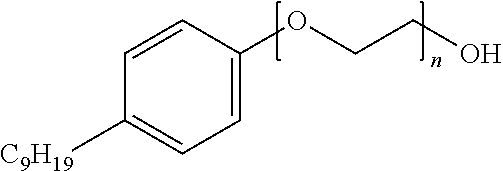
[0109] IGEPAL.RTM. CO-630 is a polyoxyethylene (9) nonylphenylether which has an average M.sub.n of 617 and the structure below and is available from SIGMA-ALDRICH.RTM..
##STR00001##
[0110] In an embodiment of the present disclosure, the polyethylene copolymer has an ESCR Condition B (10% IGEPAL.RTM. CO-630) of from at least about 10 hours (hrs).
[0111] In an embodiment of the present disclosure, the polyethylene copolymer has an ESCR Condition B (10% IGEPAL.RTM. CO-630) of from at least about 20 hours.
[0112] In an embodiment of the present disclosure, the polyethylene copolymer has an ESCR Condition B (10% IGEPAL.RTM. CO-630) of from about 1 to about 100 hours.
[0113] In an embodiment of the present disclosure, the polyethylene copolymer has an ESCR Condition B (10% IGEPAL.RTM. CO-630) of from about 10 to about 100 hours. In an embodiment of the present disclosure, the polyethylene copolymer has an ESCR Condition B (10% IGEPAL.RTM. CO-630) of from about 10 to about 75 hours.
[0114] In an embodiment of the disclosure, the polyethylene copolymer has a weight average molecular weight (M.sub.w) from about 90,000 to about 300,000 (g/mol). In other embodiments of the disclosure the polyethylene copolymer has a weight average molecular weight (M.sub.w) from about 90,000, to about 250,000, or from about 90,000 to about 225,000, or from about 90,000 to about 200,000, or from about 100,000 to about 300,000, or from about 100,000 to about 250,000, or from about 110,000 to about 225,000, or from about 125,000 to about 200,000, or from about 125,000 to about 190,000.
[0115] In an embodiment of the disclosure, the polyethylene copolymer has a molecular weight distribution (M.sub.w/M.sub.n) of from about 5.0 to about 16.0. In further embodiments of the disclosure, the polyethylene copolymer has a molecular weight distribution (M.sub.w/M.sub.n) of from about 6.0 to about 15.0, or from about 6.5 to about 14.0, or from about 6.5 to about 13.5.
[0116] In an embodiment of the disclosure, the polyethylene copolymer has an amount of terminal unsaturation of at least 0.35 per 1000 carbons (or per carbon atom), or at least 0.40 per 1000 carbons, or at least 0.45 per 1000 carbons, or greater than 0.45 per 1000 carbons, or at least 0.50 per 1000 carbons, or greater than 0.50 per 1000 carbons, or at least 0.55 per 1000 carbons, or greater than 0.55 per thousand carbons, or at least 0.60 per 1000 carbons, or greater than 0.60 per 1000 carbons, or at least 0.65 per 1000 carbons, or greater than 0.65 per 1000 carbons, or at least 0.70 per 1000 carbons, or greater than 0.70 per thousand carbons.
[0117] In an embodiment of the disclosure, the polyethylene copolymer has a total amount of unsaturation (which includes internal, side chain, and terminal unsaturation) of at least 0.40 per 1000 carbons (or per carbon atom), or at least 0.45 per 1000 carbons, or at least 0.50 per 1000 carbons, or greater than 0.50 per 1000 carbons, or at least 0.55 per 1000 carbons, or greater than 0.55 per 1000 carbons, or at least 0.60 per 1000 carbons, or greater than 0.60 per thousand carbons, or at least 0.65 per 1000 carbons, or greater than 0.65 per 1000 carbons, or at least 0.70 per 1000 carbons, or greater than 0.70 per 1000 carbons, or at least 0.75 per 1000 carbons, or greater than 0.75 per 1000 carbons.
[0118] Suitable alpha olefin comonomers for polymerization with ethylene to make the polyethylene copolymer include 1-butene, 1-hexene, and 1-octene.
[0119] In an embodiment of the disclosure, the polyethylene copolymer includes from about 0.1 to about 5 weight %, in some cases less than about 3 weight %, in other instances less than about 1.5 weight % of an alpha olefin chosen from 1-butene, 1-hexene, 1-octene, and mixtures thereof.
[0120] In an embodiment of the disclosure, the polyethylene copolymer includes polymerized ethylene and 1-butene.
[0121] Examples of polyethylene copolymers which are useful in the present disclosure include by way of non-limiting example, SCLAIR.RTM. 17A, and SCLAIR.RTM. 58A, each of which is commercially available from NOVA CHEMICALS.RTM..
[0122] In an embodiment of the disclosure, the polyethylene copolymers suitable for use in the present disclosure may be prepared using conventional polymerization processes, non-limiting examples of which include gas phase, slurry and solution phase polymerization processes. Such processes are well known to those skilled in the art.
[0123] In an embodiment of the disclosure, the polyethylene copolymers may be prepared using conventional catalysts. Some non-limiting examples of conventional catalysts include chrome based catalysts and Ziegler-Natta catalysts. Such catalysts are well known to those skilled in the art.
[0124] Solution and slurry polymerization processes are generally conducted in the presence of an inert hydrocarbon solvent/diluent, such for example, a C.sub.4-12 hydrocarbon which may be unsubstituted or substituted by a C.sub.1-4 alkyl group, such as, butane, pentane, hexane, heptane, octane, cyclohexane, methylcyclohexane, or hydrogenated naphtha. A non-limiting example of a commercial solvent is ISOPAR.RTM. E (C.sub.8-12 aliphatic solvent, Exxon Chemical Co.). The monomers are dissolved in the solvent/diluent.
[0125] A slurry polymerization process may be conducted at temperatures from about 20.degree. C. to about 180.degree. C., or from 80.degree. C. to about 150.degree. C., and the polyethylene polymer being made is insoluble in the liquid hydrocarbon diluent.
[0126] A solution polymerization process may be conducted at temperatures of from about 180.degree. C. to about 250.degree. C., or from about 180.degree. C. to about 230.degree. C., and the polyethylene polymer being made is soluble in the liquid hydrocarbon phase (e.g., the solvent).
[0127] A gas phase polymerization process can be carried out in either a fluidized bed or a stirred bed reactor. A gas phase polymerization typically involves a gaseous mixture including from about 0 to about 15 mole % of hydrogen, from about 0 to about 30 mole % of one or more C.sub.3-8 alpha-olefins, from about 15 to about 100 mole % of ethylene, and from about 0 to about 75 mole % of an inert gas at a temperature from about 50.degree. C. to about 120.degree. C., or from about 75.degree. C. to about 110.degree. C.
[0128] Suitable alpha olefins which may be polymerized with ethylene in the case of a polyethylene copolymer are C.sub.3-8 alpha olefins such as one or more of 1-butene, 1-hexene, and 1-octene.
[0129] In an embodiment of the disclosure, the polyethylene copolymer is prepared by contacting ethylene and optionally an alpha-olefin with a polymerization catalyst under solution polymerization conditions.
[0130] In an embodiment of the disclosure, the polyethylene copolymer is made in a single polymerization reactor using only one polymerization catalyst.
[0131] In an embodiment of the disclosure, the polyethylene copolymer is made in a multiple (i.e. two or more) polymerization reactors using only one polymerization catalyst.
[0132] In an embodiment of the disclosure, the polyethylene copolymer is made in a single solution polymerization reactor using only one polymerization catalyst.
[0133] In an embodiment of the disclosure, the polyethylene copolymer is made in multiple (i.e. two or more) solution polymerization reactors using only one polymerization catalyst.
[0134] In an embodiment of the disclosure, the polyethylene copolymer is made in a single solution polymerization reactor using only one polymerization catalyst, and the polymerization catalyst is a Ziegler-Natta catalyst.
[0135] In an embodiment of the disclosure, the polyethylene copolymer is made in multiple (i.e. two or more) solution polymerization reactors using only one polymerization catalyst, and the polymerization catalyst is a Ziegler-Natta catalyst.
[0136] In an embodiment of the disclosure, the polyethylene copolymer is made with a Ziegler-Natta polymerization catalyst.
[0137] In an embodiment of the disclosure, the polyethylene copolymer is made in a solution polymerization process using a Ziegler-Natta catalyst.
[0138] The term "Ziegler-Natta" catalyst is well known to those skilled in the art and is used herein to convey its conventional meaning. A Zielger-Natta catalyst may be supported or unsupported.
[0139] By way of non-limiting example, Ziegler-Natta catalysts include at least one transition metal compound of a transition metal selected from groups 3, 4, or 5 of the Periodic Table (using IUPAC nomenclature) and an organoaluminum component that is defined by the formula:
Al(X').sub.a(OR).sub.b(R).sub.c
wherein: X' is a halide (for example chlorine); OR is an alkoxy or aryloxy group; R is a hydrocarbyl (for example an alkyl having from 1 to 10 carbon atoms); and a, b, or c are each 0, 1, 2, or 3 with the provisos, a+b+c=3 and b+c.gtoreq.1. As will be appreciated by those skilled in the art of ethylene polymerization, conventional Ziegler-Natta catalysts may also incorporate additional components such as an electron donor or support materials. For example, an amine electron donor or a magnesium compound or a magnesium alkyl such as butyl ethyl magnesium and a halide source (for example a chloride such as tertiary butyl chloride) and which may form a support matrix (such as MgCl.sub.2 or chloride deficient MgCl.sub.2 both of which are well known in the art). Ziegler-Natta catalyst components may be combined off-line or they may be combined in-line on route to a polymerization zone or they may be combined directly within a polymerization reactor zone. Ziegler-Natta catalysts may also be "tempered" (i.e. heat treated) prior to being introduced to a reactor (again, using techniques which are well known to those skilled in the art and published in the literature).
[0140] In an embodiment of the disclosure, the polyethylene copolymer has less than 1.5 ppm, or less than 1.3 ppm, or .ltoreq.1.0 ppm, or .ltoreq.0.9 ppm, or .ltoreq.0.8, or less than 0.8 ppm, or .ltoreq.0.75 ppm, or less than 0.50 ppm of titanium (Ti) present.
[0141] In an embodiment of the disclosure, the polyethylene copolymer has less than 1.5 ppm, or less than 1.3 ppm, or .ltoreq.1.0 ppm, or .ltoreq.0.9 ppm, or .ltoreq.0.8 ppm, or .ltoreq.0.75, or .ltoreq.0.60 ppm of aluminum (Al) present.
[0142] In an embodiment of the disclosure, the polyethylene copolymer has less than 0.5 ppm, or less than 0.4 ppm, or .ltoreq.0.3 ppm, or .ltoreq.0.2 ppm, or .ltoreq.0.15 ppm, or .ltoreq.0.1 ppm, of chlorine (CI) present.
[0143] In an embodiment of the disclosure, the polyethylene copolymer has less than 4.0 ppm, or less than 3.0 ppm, or .ltoreq.2.5 ppm, or .ltoreq.2.0 ppm, of magnesium (Mg) present.
[0144] In an embodiment of the disclosure, the polyethylene copolymer includes one or more nucleating agents.
[0145] In an embodiment of the disclosure, the polyethylene copolymer includes a nucleating agent or a mixture of nucleating agents.
[0146] The polyethylene copolymer may be compounded or dry-blended either by a manufacturer or a converter (e.g., the company converting the resin pellets into the final product). The compounded or dry-blended polyethylene copolymers may contain fillers, pigments and other additives. Typically, fillers are inert additives, such as, clay, talc, TiO.sub.2 and calcium carbonate, which may be added to the polyolefin copolymer in amounts from about 0 weight % up to about 50 weight %, in some cases, less than 30 weight % of fillers are added. The compounded or dry-blended polyethylene copolymers may contain antioxidants, heat and light stabilizers, such as, combinations of one or more of hindered phenols, phosphates, phosphites and phosphonites, typically, in amounts of less than about 0.5 weight % based on the weight of the polyethylene polymer. Pigments may also be added to the polyethylene copolymers in small amounts. Non-limiting examples of pigments include carbon black, phthalocyanine blue, Congo red, titanium yellow, etc.
[0147] The polyethylene copolymers may contain a nucleating agent or a mixture of nucleating agents in amounts of from about 5 parts per million (ppm) to about 10,000 ppm based on the weight of the polyethylene polymer. The nucleating agent may be chosen from dibenzylidene sorbitol, di(p-methylbenzylidene) sorbitol, di(o-methylbenzylidene) sorbitol, di(p-ethylbenzylidene) sorbitol, bis(3,4-dimethylbenzylidene) sorbitol, bis(3,4-diethylbenzylidene) sorbitol and bis(trimethylbenzylidene) sorbitol. One commercially available nucleating agent is bis(3,4-dimethylbenzylidene) sorbitol.
[0148] Optionally, additives can be added to the polyethylene copolymer. Additives can be added to the polyethylene copolymer during an extrusion or compounding step, but other suitable known methods will be apparent to a person skilled in the art. The additives can be added as is or as part of a separate polymer component added during an extrusion or compounding step. Suitable additives are known in the art and include but are not-limited to antioxidants, phosphites and phosphonites, nitrones, antacids, UV light stabilizers, UV absorbers, metal deactivators, dyes, fillers and reinforcing agents, nano-scale organic or inorganic materials, antistatic agents, lubricating agents such as calcium stearates, slip additives such as erucimide and behenamide, and nucleating agents (including nucleators, pigments or any other chemicals which may provide a nucleating effect to the polyethylene copolymer). The additives that can be optionally added are typically added in amount of up to 20 weight percent (wt %).
[0149] One or more nucleating agent(s) may be introduced into the polyethylene copolymer by kneading a mixture of the polymer, usually in powder or pellet form, with the nucleating agent, which may be utilized alone or in the form of a concentrate containing further additives such as stabilizers, pigments, antistatics, UV stabilizers and fillers. It may be a material which is wetted or absorbed by the polymer, which may be insoluble in the polymer and which may have a melting point higher than that of the polymer, and it may be homogeneously dispersible in the polymer melt in as fine a form as possible (1 to 10 .mu.m). Compounds known to have a nucleating capacity for polyolefins include salts of aliphatic monobasic or dibasic acids or arylalkyl acids, such as sodium succinate, or aluminum phenylacetate; and alkali metal or aluminum salts of aromatic or alicyclic carboxylic acids such as sodium .beta.-naphthoate, or sodium benzoate.
[0150] Examples of nucleating agents which are commercially available and which may be added to the polyethylene copolymer are dibenzylidene sorbital esters (such as the products sold under the trademark Millad 3988.TM. by Milliken Chemical and IRGACLEAR.RTM. by Ciba Specialty Chemicals). Further examples of nucleating agents which may added to the polyethylene copolymer include the cyclic organic structures disclosed in U.S. Pat. No. 5,981,636 (and salts thereof, such as disodium bicyclo [2.2.1] heptene dicarboxylate); the saturated versions of the structures disclosed in U.S. Pat. No. 5,981,636 (as disclosed in U.S. Pat. No. 6,465,551; Zhao et al., to Milliken); the salts of certain cyclic dicarboxylic acids having a hexahydrophtalic acid structure (or "HHPA" structure) as disclosed in U.S. Pat. No. 6,599,971 (Dotson et al., to Milliken); and phosphate esters, such as those disclosed in U.S. Pat. No. 5,342,868 and those sold under the trade names NA-11 and NA-21 by Asahi Denka Kogyo, cyclic dicarboxylates and the salts thereof, such as the divalent metal or metalloid salts, (for example, calcium salts) of the HHPA structures disclosed in U.S. Pat. No. 6,599,971. For clarity, the HHPA structure generally includes a ring structure with six carbon atoms in the ring and two carboxylic acid groups which are substituents on adjacent atoms of the ring structure. The other four carbon atoms in the ring may be substituted, as disclosed in U.S. Pat. No. 6,599,971. An example is 1,2-cyclohexanedicarboxylicacid, calcium salt (CAS registry number 491589-22-1). Still further examples of nucleating agents which may added to the polyethylene copolymer include those disclosed in WO2015042561, WO2015042563, WO2015042562 and WO 2011050042.
[0151] Many of the above described nucleating agents may be difficult to mix with the polyethylene copolymer that is being nucleated and it is known to use dispersion aids, such as, for example, zinc stearate, to mitigate this problem.
[0152] In an embodiment of the disclosure, the nucleating agents are well dispersed in the polyethylene copolymer.
[0153] In an embodiment of the disclosure, the amount of nucleating agent used is comparatively small--from 5 to 3000 parts by million per weight (based on the weight of the polyethylene copolymer) so it will be appreciated by those skilled in the art that some care is taken to ensure that the nucleating agent is well dispersed. In an embodiment of the disclosure, the nucleating agent is added in finely divided form (less than 50 microns, for example less than 10 microns) to the polyethylene copolymer to facilitate mixing. In some embodiments, this type of "physical blend" (i.e., a mixture of the nucleating agent and the resin in solid form) may be preferable to the use of a "masterbatch" of the nucleator (where the term "masterbatch" refers to the practice of first melt mixing the additive--the nucleator, in this case--with a small amount of the polyethylene copolymer resin--then melt mixing the "masterbatch" with the remaining bulk of the polyethylene copolymer resin).
[0154] In an embodiment of the disclosure, an additive such as nucleating agent may be added to the polyethylene copolymer by way of a "masterbatch", where the term "masterbatch" refers to the practice of first melt mixing the additive (e.g., a nucleator) with a small amount of the polyethylene copolymer, followed by melt mixing the "masterbatch" with the remaining bulk of the polyethylene copolymer.
[0155] In an embodiment of the disclosure, the polyethylene copolymer further includes a nucleating agent or a mixture of nucleating agents.
[0156] Since the polyethylene composition is used in bottle closure assemblies typically used for food contact applications, the additive package should meet the appropriate food regulations, such as, the FDA regulations in the United States.
[0157] In an embodiment of the disclosure, the polyethylene copolymer described above is used in the formation of molded articles. For example, articles formed by continuous compression molding and injection molding are contemplated. Such articles include, for example, bottle closure assemblies, caps, hinged caps, screw caps, closures and hinged closures for bottles.
[0158] The polyethylene copolymers described above are used in the formation of bottle closure assemblies. For example, bottle closure assemblies formed in part on in whole by compression molding and/or injection molding are contemplated.
[0159] In one embodiment, the bottle closure assembly includes the polyethylene copolymer described above has good organoleptic properties. The bottle closure assemblies are well suited for sealing bottles, containers, and the like, for examples bottles that may contain drinkable water, and other foodstuffs, including but not limited to liquids that are pressurized (e.g., carbonated beverages or appropriately pressurized drinkable liquids). The bottle closure assemblies may also be used for sealing bottles containing drinkable water or non-carbonated beverages (e.g., juice). Other applications include bottle closure assemblies for bottles and containers containing foodstuffs, such as for example ketchup bottles and the like.
[0160] The bottle closure assemblies of the current disclosure can be made according to any known method, including for example injection molding and compression molding techniques that are well known to persons skilled in the art. Hence, in an embodiment of the disclosure, a bottle closure assembly including polyethylene copolymer (defined above) is prepared with a process including at least one compression molding step and/or at least one injection molding step.
[0161] Further non-limiting details of the disclosure are provided in the following examples. The examples are presented for the purpose of illustrating selected embodiments of this disclosure, it being understood that the examples presented do not limit the claims presented.
Examples
[0162] Melt indexes, I.sub.2,I.sub.5,I.sub.6 and I.sub.21 for the polyethylene copolymer were measured according to ASTM D1238 (when conducted at 190.degree. C., using a 2.16 kg, a 5 kg, a 6.48 kg and a 21 kg weight respectively).
[0163] M.sub.n, M.sub.w, and M.sub.z (g/mol) were determined by high temperature Gel Permeation Chromatography with differential refractive index detection using universal calibration (e.g., ASTM-D6474-99). GPC data was obtained using an instrument sold under the trade name "Waters 150c", with 1,2,4-trichlorobenzene as the mobile phase at 140.degree. C. The samples were prepared by dissolving the polymer in this solvent and were run without filtration. Molecular weights are expressed as polyethylene equivalents with a relative standard deviation of 2.9% for the number average molecular weight ("M.sub.n") and 5.0% for the weight average molecular weight ("M.sub.w"). The molecular weight distribution (MWD) is the weight average molecular weight divided by the number average molecular weight, M.sub.w/M.sub.n. The z-average molecular weight distribution is M.sub.z/M.sub.n. Polymer sample solutions (1 to 2 mg/mL) were prepared by heating the polymer in 1,2,4-trichlorobenzene (TCB) and rotating on a wheel for 4 hours at 150.degree. C. in an oven. The antioxidant 2,6-di-tert-butyl-4-methylphenol (BHT) was added to the mixture in order to stabilize the polymer against oxidative degradation. The BHT concentration was 250 ppm. Sample solutions were chromatographed at 140.degree. C. on a PL 220 high-temperature chromatography unit equipped with four Shodex columns (HT803, HT804, HT805 and HT806) using TCB as the mobile phase with a flow rate of 1.0 mL/minute, with a differential refractive index (DRI) as the concentration detector. BHT was added to the mobile phase at a concentration of 250 ppm to protect the columns from oxidative degradation. The sample injection volume was 200 mL. The raw data were processed with CIRRUS.RTM. GPC software. The columns were calibrated with narrow distribution polystyrene standards. The polystyrene molecular weights were converted to polyethylene molecular weights using the Mark-Houwink equation, as described in the ASTM standard test method D6474.
[0164] Primary melting peak (.degree. C.), heat of fusion (J/g) and crystallinity (%) was determined using differential scanning calorimetry (DSC) as follows: the instrument was first calibrated with indium; after the calibration, a polymer specimen is equilibrated at 0.degree. C. and then the temperature was increased to 200.degree. C. at a heating rate of 10.degree. C./min; the melt was then kept isothermally at 200.degree. C. for five minutes; the melt was then cooled to 0.degree. C. at a cooling rate of 10.degree. C./min and kept at 0.degree. C. for five minutes; the specimen was then heated to 200.degree. C. at a heating rate of 10.degree. C./min. The DSC Tm, heat of fusion and crystallinity are reported from the 2.sup.nd heating cycle.
[0165] The short chain branch frequency (SCB per 1000 carbon atoms) of the polyethylene copolymer was determined by Fourier Transform Infrared Spectroscopy (FTIR) as per the ASTM D6645-01 method. A Thermo NICOLET.RTM. 750 Magna-IR Spectrophotometer equipped with OMNIC.RTM. version 7.2a software was used for the measurements. Unsaturations in the polyethylene copolymer (terminal, side chain and internal) were also determined by Fourier Transform Infrared Spectroscopy (FTIR) as per ASTM D3124-98. Comonomer content can also be measured using .sup.13C NMR techniques as discussed in Randall, Rev. Macromol. Chem. Phys., C29 (2&3), p 285; U.S. Pat. No. 5,292,845 and WO 2005/121239.
[0166] Polyethylene copolymer density (g/cm.sup.3) was measured according to ASTM D792.
[0167] Hexane extractables were determined according to ASTM D5227.
[0168] To determine CDBI(50), a solubility distribution curve is first generated for the polyethylene copolymer. This is accomplished using data acquired from the TREF technique. This solubility distribution curve is a plot of the weight fraction of the copolymer that is solubilized as a function of temperature. This is converted to a cumulative distribution curve of weight fraction versus comonomer content, from which the CDBI(50) is determined by establishing the weight percentage of a copolymer sample that has a comonomer content within 50% of the median comonomer content on each side of the median (See WO 93/03093 and U.S. Pat. No. 5,376,439). The CDBI(25) is determined by establishing the weight percentage of a copolymer sample that has a comonomer content within 25% of the median comonomer content on each side of the median
[0169] The temperature rising elution fractionation (TREF) method used herein was as follows. Polymer samples (50 to 150 mg) were introduced into the reactor vessel of a crystallization-TREF unit (Polymer Char). The reactor vessel was filled with 20 to 40 ml 1,2,4-trichlorobenzene (TCB), and heated to the desired dissolution temperature (e.g., 150.degree. C.) for 1 to 3 hours. The solution (0.5 to 1.5 ml) was then loaded into the TREF column filled with stainless steel beads. After equilibration at a given stabilization temperature (e.g., 110.degree. C.) for 30 to 45 minutes, the polymer solution was allowed to crystallize with a temperature drop from the stabilization temperature to 30.degree. C. (0.1 or 0.2.degree. C./minute). After equilibrating at 30.degree. C. for 30 minutes, the crystallized sample was eluted with TCB (0.5 or 0.75 mL/minute) with a temperature ramp from 30.degree. C. to the stabilization temperature (0.25 or 1.0.degree. C./minute). The TREF column was cleaned at the end of the run for 30 minutes at the dissolution temperature. The data were processed using Polymer Char software, Excel spreadsheet and TREF software developed in-house.
[0170] High temperature GPC equipped with an online FTIR detector (GPC-FTIR) was used to measure the comonomer content as the function of molecular weight.
[0171] Plaques molded from the polyethylene copolymers were tested according to the following ASTM methods: Bent Strip Environmental Stress Crack Resistance (ESCR) at Condition B at 10% and 100% IGEPAL.RTM. CO-630 at 50.degree. C., ASTM D1693; notched Izod impact properties, ASTM D256; Flexural Properties, ASTM D790; Tensile properties, ASTM D638; Vicat softening point, ASTM D1525; Heat deflection temperature, ASTM D648.
[0172] The polymer used in Example 1 is a polyethylene ethylene/1-hexene copolymer and has a density of 0.957 g/cm.sup.3, a melt index 12 of 0.46 g/10 min and is commercially available from EXXONMOBIL.RTM. as EXXONMOBIL.RTM. HPDE HD 9856B.
[0173] The polymer used in Example 2 is a polyethylene copolymer made with a chromium-based polymerization catalyst in a gas phase polymerization process. The Example 2 polymer is an ethylene/1-hexene copolymer and has a density of 0.949 g/cm.sup.3, a melt index 12 of 0.40 g/10 min and is commercially available from NOVA CHEMICALS.RTM. as NOVAPOL.RTM. HF-Y450-A.
[0174] The polymer used in Example 3 is a polyethylene copolymer made with a Ziegler-Natta catalyst in a solution polymerization process. The Example 3 polymer is an ethylene/1-butene copolymer, and has a density of 0.950 g/cm.sup.3, a melt index 12 of 0.45 g/10 min and is commercially available from NOVA CHEMICALS.RTM. as SCLAIR.RTM. 17A. A GPC profile for the polymer of Example 3 is shown in FIG. 8.
[0175] The polymer used in Example 4 is a polyethylene copolymer made with a Ziegler-Natta catalyst in a solution polymerization process. The Example 4 polymer is an ethylene/1-butene copolymer, and has a density of 0.957 g/cm.sup.3, a melt index 12 of 0.41 g/10 min and is commercially available from NOVA CHEMICALS.RTM. as SCLAIR.RTM. 58A. A GPC profile for the polymer of Example 4 is shown in FIG. 9.
[0176] Further data for each of the polymers used in Examples 1-4 is provided in Table 1 together with their plaque data.
TABLE-US-00001 TABLE 1 Polymer and Plaque Properties Example No. 1 2 3 4 Density (g/cm.sup.3) 0.957 0.949 0.950 0.957 Melt Index I.sub.2 0.46 0.40 0.45 0.41 (g/10 min) Melt Flow Ratio (I.sub.21/I.sub.2) 93.8 83.9 96.7 Stress Exponent 1.89 1.78 1.86 M.sub.n 13959 14344 17949 13786 M.sub.w 146950 122544 165205 160821 M.sub.z 875145 602266 938029 911830 Polydispersity Index (M.sub.w/M.sub.n) 10.53 8.54 9.20 11.67 M.sub.z/M.sub.w 5.96 4.91 5.68 5.67 Branch Frequency - FTIR (uncorrected for chain end --CH.sub.3) Uncorrected SCB/1000 C <0.5 2.7 1.2 <0.5 Uncorrected comonomer content <0.1 0.5 0.2 <0.1 (mol %) Internal unsaturation (/1000 C) 0.050 0.070 0.040 Side chain unsaturation (/1000 C) 0.110 0.040 0.020 Terminal unsaturation (/1000 C) 1.130 0.800 0.730 Total unsaturation 1.29 0.910 0.790 Comonomer ID 1-hexene 1-hexene 1-butene 1-butene TREF CDBI.sub.50 (%) 66.8 58.3 70.8 69.1 TREF CDBI.sub.25 (%) 46.6 36.2 58.3 60 DSC Primary Melting Peak (.degree. C.) 131.61 128.47 129.74 132.23 Heat of Fusion (J/g) 219.2 194.00 207.40 210.10 Crystallinity (%) 75.57 66.89 71.51 72.46 Environmental Stress Crack Resistance ESCR Cond. A at 100% (hrs) 151 -- -- -- ESCR Cond. B at 100% (hrs) -- >1154 93 44 ESCR Cond. B at 10% (hrs) 66 73 44 26 Flexural Properties (Plaques) Flex Secant Mod. 2% (MPa) 928 951 1165 Impact Properties (Plaques) Izod Impact (ft-lb/in) 2.50 1.40 1.90 Other properties Hexane Extractables (%) 0.57 0.85 0.53 VICAT Soft. Pt. (.degree. C.) - Plaque 124.7 126.2 129.1 Heat Deflection Temp. [.degree. C.] @ 66 PSI 64.7 62 72.9
Neutron Activation Analysis (NAA)
[0177] Neutron Activation Analysis, hereafter NAA, was used to determine catalyst residues in ethylene polymers and was performed as follows. A radiation vial (composed of ultrapure polyethylene, 7 mL internal volume) was filled with a polyethylene polymer product sample and the sample weight was recorded. Using a pneumatic transfer system the sample was placed inside a SLOWPOKE.RTM. nuclear reactor (Atomic Energy of Canada Limited, Ottawa, Ontario, Canada) and irradiated for 30 to 600 seconds for short half-life elements (e.g., Ti, V, Al, Mg, and Cl) or 3 to 5 hours for long half-life elements (e.g., Zr, Hf, Cr, Fe and Ni). The average thermal neutron flux within the reactor was 5.times.10.sup.11/cm.sup.2/s. After irradiation, samples were withdrawn from the reactor and aged, allowing the radioactivity to decay; short half-life elements were aged for 300 seconds or long half-life elements were aged for several days. After aging, the gamma-ray spectrum of the sample was recorded using a germanium semiconductor gamma-ray detector (ORTEC.RTM. model GEM55185, Advanced Measurement Technology Inc., Oak Ridge, Tenn., USA) and a multichannel analyzer (ORTEC model DSPEC Pro). The amount of each element in the sample was calculated from the gamma-ray spectrum and recorded in parts per million relative to the total weight of the polymer sample. The N.A.A. system was calibrated with Specpure standards (1000 ppm solutions of the desired element (greater than 99% pure)). One mL of solutions (elements of interest) were pipetted onto a 15 mm.times.800 mm rectangular paper filter and air dried. The filter paper was then placed in a 1.4 mL polyethylene irradiation vial and analyzed by the N.A.A. system. Standards are used to determine the sensitivity of the N.A.A. procedure (in counts/.mu.g). The results of NAA analysis (i.e. catalyst residue levels in ppm, present in the polymer based on the weight of the polymer) for Examples 2-4 are given in Table 2.
TABLE-US-00002 TABLE 2 NAA of Polyethylene Polymers Example No. 2 3 4 Cr (ppm) 0.72 <0.1 <0.2 Al (ppm) 1.1 0.92 0.74 Cl (ppm) 0.19 0.06 0.05 Mg (ppm) <2 <2 <2 Ti (ppm) 0.45 0.32 0.46
Evaluation of Organoleptics/Water Taste Testing
[0178] Caps made from the polymer of Example 1 were used for the water taste testing outlined below. The caps were 2.5 g with a surface area of 48.26 cm.sup.2. 20 caps were used to give a total surface area of 965 cm.sup.2. Plaque specimens were prepared, and then cut to a predetermined size, for testing the polymers used in Examples 2 and 3.
[0179] For the polymers of Examples 2 and 3, a melt was prepared from polymer pellets by using a Brabender compounder at a melt temperature of 170.degree. C. and rpm of 100. Next, 145 g of the melted polymer was pressed into a compression molded plaque having the dimensions 10 inches by 10 inches and a 75 mil thickness. The plaque was wrapped in aluminum foil and stored in the freezer. Plaques were trimmed to a size of less than 24 cm by 21 cm to give a total surface area of 965 cm.sup.2 and then cut into 6 pieces so that the pieces could be placed in a Mason jar. The 6 plaque pieces obtained in this manner for each of Examples 2 and 3, as well as the 20 caps for Example 1 were placed in clean Mason jars which were then filled with approximately 1 liter of bottled spring water (REAL CANADIAN Natural Spring Water.TM.). Each jar was sealed with a piece of aluminum foil and a lid. For use as a control, bottled spring water was also added to a Mason jar in the absence of polymer plaque pieces or caps. Each of the jars (including the control) was placed in a 60.degree. C. water bath for 4 hours. The jars were then removed from the bath and the plaques or caps were removed from the jars. The jars were resealed and all the jars were left to cool to room temperature. Water samples for the taste panel were prepared by pouring the above sample water from each of the jars into separate 2 ounce polystyrene sample cups, each with an identifying code attached to it. For each water sample, a randomly generated 3 digit code was used to ensure the tasting was a blind tasting where panelists were not given information about the water samples they were tasting. Each panelist was provided with an instruction sheet that explains how to conduct the taste test. Before the test, the palate is cleansed with an unsalted cracker. Up to six water samples, including a control, were tasted by each panelist. The same water samples were tasted by each panelist. The water samples were presented in one of four different orders. The panelists ranked each water sample on the following scale to provide a "water taste testing score": 7=Completely Acceptable (no flavor or taste detected); 6=Moderately Acceptable; 5=Slightly Acceptable; 4=Neither Acceptable nor Unacceptable; 3=Slightly Unacceptable; 2=Moderately Unacceptable; 1=Completely Unacceptable. If a panelist does not detect the control, by assigning the control a score of 5 or higher, the results from that panelist were not included in the final statistical analysis. The results are analyzed using analysis of variance and an average water taste testing score is reported for each water sample as shown in Table 3.
TABLE-US-00003 TABLE 3 Organoleptics (Water Taste Testing Score) Example No. Control (spring water stored 1 2 3 in glass jar) Taste Panel Rating - average water 3.3 2.9 6 6.7 taste testing score Taste Panel Rating - standard error 0.44 0.48 0.3 0.09
[0180] As can be seen from the data in Table 3, each of the water samples containing caps made from the resin of Example 1 or plaque material made from the resin of Example 2 had poor performance using the water taste testing procedure. In contrast, the water samples containing plaque material made from the resin of Example 3, had a performance just below that of the control sample, consistent with very good organoleptic properties for this material. Good organoleptic properties are desirable when making a bottle closure or a cap portion of a bottle closure assembly when they are not used in combination with a liner. This is because the closure or cap portion may come in direct contact with consumable liquid or foodstuffs held within the bottle, container, or the like, which the closure or cap portion (of a bottle closure assembly) is sealing.
[0181] A comparison of Table 3 with the catalyst component residue data in Table 2, is consistent with the fact that when higher levels of catalyst residue remain in a polyethylene polymer it leads to poorer organoleptic properties. Compare for example, the catalyst residues present in Example 2, with the catalyst residues present in Example 3. Example 2 has 0.72 ppm or chromium present, an aluminum residue level of greater than 1 ppm, and 0.19 ppm of chlorine. In contrast, Example 3 has negligible amounts of chromium present, less than 1 ppm of aluminum and 0.06 ppm of chlorine present. For similar reasons, a person skilled in the art would expect Example 4 to have good organoleptic properties, as it has low levels of catalyst residues present. In contrast, the poor taste testing performance of Example 1, indicates that there may be significant levels of catalyst component residues present.
[0182] For end use applications, especially those which may come in contact with foodstuff it may be desirable to employ products having lower levels of catalyst component residues. Lower catalyst residues may lead to better organoleptic properties and help preserve the original taste and odor of the packaged contents.
[0183] The polyethylene copolymers described above can be used in the formation of bottle closure assemblies. For example, bottle closure assemblies formed in part on in whole by compression molding and/or injection molding are contemplated.
[0184] In one embodiment, the bottle closure assembly includes the polyethylene copolymers described above and has good organoleptic properties. Hence the bottle closure assemblies are well suited for sealing bottles, containers, and the like, for example bottles that may contain drinkable water, and other foodstuffs, including but not limited to liquids that are pressurized or non-pressurized.
[0185] In an embodiment of the disclosure, a bottle closure assembly including a polyethylene copolymer defined as above is prepared with a process including at least one compression molding step and/or at least one injection molding step.
Preparation of a Tether Proxy for Deformation Testing
[0186] In order to provide a proxy of a tether portion which can be analyzed under conditions of shear, tear and tensile deformation, a closure (see FIGS. 10A and 10B) was compression molded as described below and then a tamper evident band, 10* (a proxy for a retaining means portion, 10) was formed by folding in and cutting the bottom circular edge of the closure using a folding/slitting machine with a modified blade, so that a tamper evident band (10*) which was joined to the cap portion (1) by several narrow ("pin" like) connecting sections (marked by the frangible line, 9 in FIGS. 10A and 10B) and one larger continuous section (i.e. continuous with a portion of the cap portion side wall), with the larger continuous section serving as a proxy for a tether (the area marked as 40 in FIGS. 10A and 10B). The larger continuous section or "tether proxy" section was designed to have an arcuate length of 6 mm. The "tether proxy" section had a cross-sectional width (or thickness) of 0.6 mm as determined by the dimensions of the closure mold used for the compression molding process (see below). The "tether proxy" section, or simply "tether proxy" 40 was then subjected to shear and tear deformations and to tensile deformation using a toque tester unit and tensile tester unit respectively (see below).
Method of Making a Closure by Compression Molding
[0187] A SACMI Compression molding machine (model CCM24SB) and a PCO (plastic closure only) 1881 carbonated soft drink (CSD) closure mold was used to prepare the closures. Depending on material density, melt index (12) and chosen plug size, the closure weight varied between 2.15 g and 2.45 grams, with the process conditions adjusted to target a closure having a weight of about 2.3 grams. During the closure preparation process, the overall closure dimensions, such as, for the example, the closure diameter and the closure height were measured and maintained within desired "quality-controlled" specifications. Closures with poor circularity or with significant deformation away from the pre-defined specifications were rejected by an automatic vision system installed on the compression molding machine. Once the closure had been compression molded, a tamper evident band, inclusive of one larger continuous section (a proxy for a tether portion) was cut into the closure bottom edge using a folding/slitting machine fitted with a modified blade. Both experimental and simulated data confirmed that 99% of any closure weight differences were due to differences in the top panel thickness (of the cap portion, see FIG. 10A) for each of the compression molded closures. For example, in the closures prepared by compression molding, the top panel thickness values of closures having a weight ranging from 2.15 grams to 2.45 grams were found to be slightly different, but each of the closure side wall thicknesses were found to be identical. As a result, any small differences in the compression molded cap weight were expected to have no impact on the dimensions of the tamper evident band or the tether proxy section (see above): in each case, the tether proxy had an arcuate length of 6 mm and a cross-sectional thickness of 0.6 mm.
[0188] Type 1 closures were compression molded from an ethylene/1-butene copolymer (Example 4), having a density of 0.957 g/cm.sup.3, a melt index 12 of 0.41 g/10 min and which is commercially available from NOVA CHEMICALS.RTM. as SCLAIR.RTM. 58A.
[0189] Type 2 closures (Comparative) were compression molded from a unimodal polyethylene copolymer of ethylene and 1-butene having a melt index 12 of 32 g/10 min, a density of 0.951 g/cm.sup.3, and a molecular weight distribution, M.sub.w/M.sub.n of 2.88, and which is made using a Ziegler-Natta catalyst in a solution olefin polymerization process. This resin is commercially available from NOVA CHEMICALS.RTM. as SCLAIR.RTM. 2712.
[0190] The compression molding conditions used to make each closure type are provided in Table 4.
TABLE-US-00004 TABLE 4 Compression Molding Processing Conditions Closure Type No. 2 1 (Comparative) Closure Weight (g) 2.3 2.39 BT1 Temp (.degree. C.) 168 163 BT2 Temp (.degree. C.) 170 164 BT3 Temp (.degree. C.) 174 163 BT4 Temp (.degree. C.) 175 161 BT6 Temp (.degree. C.) 175 170 BT7 Temp (.degree. C.) 185 187 BT8 Temp (.degree. C.) 185 184 BT9 Temp (.degree. C.) 185 184 BT15 Temp (.degree. C.) 175 170 BT16 Temp (.degree. C.) 174 165 BT17 Temp (.degree. C.) 182 174 Metering Pump Set Press 50 50 (bar) Metering Pump Actual Press 50 50 1 (bar) IN Metering Pump Actual Press 146 30.6 2 (bar) OUT Pump Speed (%) 59 57 Hydraulic Operating Temp 45 46 (.degree. C.) Punch Cooling BT18 (.degree. C.) 20 20 Cavity Cooling BT19 (.degree. C.) 20 20 Ausiliari Cooling BT20 (.degree. C.) 30 30
Shear Deformation of a Tether Proxy
[0191] A TMS 5000 Torque Tester unit manufactured by Steinfurth was used to carry out the tether proxy shear deformation testing. The unit was adjusted to operate in "removal torque mode". A closure having a tether proxy section (area 40 in FIGS. 10A and 10B) with a 6 mm arcuate length and a 0.6 mm cross-sectional width connecting a cap portion (1) to a tamper evident band 10* (a proxy for a retaining means portion, 10) and suitable for mating with a PCO 1881 bottle finish was employed. Prior to testing, the tamper evident band (10*) was unfolded and then almost entirely removed, by cutting through the tamper evident band at a distance of approximately 2 mm from each end of the tether proxy section. The remaining portion of the tamper evident band (as shown in FIGS. 11A and 11B) then, includes the tether proxy section having an arcuate length of 6 mm, and a further 2 mm arcuate length section on either side of the tether proxy section, all of which has a cross sectional width of 0.6 mm. Adding 2 mm to either side of the tether proxy section provides a larger surface area to grip when carrying out the shear deformation testing. In order to support the closure for testing in the Torque Tester unit, a modified tubular preform was used (item 45 in FIG. 11B). The tubular pre-form 45 was made of polyethylene terephthalate and was modified to have smooth outer walls. Following this, a brass rod (50), having a diameter which fit snuggly within the preform (45) was inserted as a plug to afford rigidity to the pre-form and to prevent its deformation during testing. Next, the closure was placed on top of the pre-form and the remaining section of the tamper evident band (10*) was clamped to the preform using vice grips. The closure and preform were then mounted within the Torque Tester. The cap portion (1) was gripped from above within a suitably designed chuck and rotated at a removal torque speed of 0.8 rpm, relative to the clamped section of the tamper evident band, using the Torque Tester. The shear strength of the tether proxy (40) is defined as the maximum torque (in inches.pounds) required to separate the cap portion (1) from the remaining section of the tamper evident band section (10*) by breaking the tether proxy (40). The reported shear strength in Table 5 is the average of at least 5 such shear deformation tests.
Tear Deformation of a Tether Proxy
[0192] A TMS 5000 Torque Tester unit manufactured by Steinfurth was used to carry out the tether proxy shear deformation testing. The unit was adjusted to operate in "removal torque mode". A closure having a tether proxy section (area 40 in FIGS. 10A and 10B) with a 6 mm arcuate length and a 0.6 mm cross-sectional width connecting a cap portion (1) to a tamper evident band 10* (a proxy for a retaining means portion, 10) and suitable for mating with a PCO 1881 bottle finish was employed. In order to support the closure for testing in the Torque Tester unit, a modified tubular pre-form was used (item 45 in FIG. 11C). The tubular pre-form 45 was made of polyethylene terephthalate and was modified to have smooth outer walls. Following this, a brass rod (50), having a diameter which fit snuggly within the pre-form (45) was inserted as a plug to afford rigidity to the pre-form and to prevent its deformation during testing. Next, the closure was placed on top of the preform. Prior to testing, the tamper evident band (10*) was deflected downward (on the opposite side of the tether proxy section) and away from the cap portion (1) as is shown in FIG. 11C. The downward deflection breaks all the narrow pin sections (the frangible line 9 in FIGS. 10A and 10B) joining the top edge of the tamper evident band to the lower edge of the cap portion while leaving the larger continuous section, the tether proxy section (40), intact. The tamper evident band (10*) is deflected downward and away from the cap portion (1) until the top edge of the tamper evident band makes an angle with the lower edge of the cap portion of about 27 degrees, while the tether portion remains intact along its 6 mm arcuate length (see FIG. 11C). The tamper evident band (10*) was then clamped to the pre-form in this downwardly deflected position using vice grips. The closure and pre-form were then mounted within the Torque Tester. The cap portion (1) was gripped from above within a suitably designed chuck and rotated at a removal torque speed of 0.8 rpm, relative to the clamped tamper evident band (10*), using the Torque Tester. The tear strength of the tether proxy (40) is defined as the maximum torque (in inches.pounds) required to separate the cap portion (1) from the downwardly deflected tamper evident band (10*) by breaking the tether proxy (40). The reported tear strength in Table 5 is the average of at least 5 such tear deformation tests.
Tensile Deformation of a Tether Proxy
[0193] Tensile deformation tests were performed using a tensile machine (an Instron 4204 universal tester, with a 1 KN (225 lbf) capacity load cell) with the crosshead velocity set at 50 mm/min. A closure having a tether proxy section (area 40 in FIGS. 10A and 10B) with a 6 mm arcuate length and a 0.6 mm cross-sectional width connecting a cap portion (1) to a tamper evident band 10* (a proxy for a retaining means portion, 10) and suitable for mating with a PCO 1881 bottle finish was employed. Prior to testing, the tamper evident band (10*) was unfolded and then almost entirely removed, by cutting through the tamper evident band at a distance of approximately 2 mm from each end of the tether proxy section (see FIGS. 11A, 12A and 12B). The remaining portion of the tamper evident band (as shown in FIGS. 11A, 12A and 12B) then, includes the tether proxy section having an arcuate length of 6 mm, and a further 2 mm arcuate length section on either side of the tether proxy section, all of which has a cross sectional width of 0.6 mm. Adding 2 mm to either side of the tether proxy section provides a larger surface area to grip when carrying out the tensile deformation testing. For the tensile deformation test, most of the cap portion (1) was similarly cut away, leaving only a section of the cap portion side wall connected to the what was left of the tamper evident band (see FIGS. 12A and 12B). This "cut away" section of the closure was then mounted in the tensile tester, with the remaining cap portion side wall and the remaining tamper evident band each being secured with 0.5-inch wide steel serrated grips at a 0.25-inch grip separation. During the tensile testing, the remaining section of the cap portion (1) and the remaining section of the tamper evident band (10*) were drawn apart vertically. The tensile strength of the tether proxy (40) is defined as the maximum load (in grams.force, gf) required to separate the remaining cap portion (1) from the remaining tamper evident band section (10*) by breaking the tether proxy (40). The reported tensile strength in Table 5 is the average of at least 5 such tensile deformation tests.
TABLE-US-00005 TABLE 5 Average Shear, Tear and Tensile Deformation of a Tether Proxy Closure Type No. 2 1 (Comparative) Shear Strength 11.96 9.43 (inches pounds) Tear Strength 11.56 9.18 (inches pounds) Tensile Strength 16448 12800 (grams force)
[0194] A person skilled in the art will recognize from the data provided in Table 5, that a tether proxy made using a polyethylene copolymer according to the current disclosure may have a relatively good ability to resist shear, tear and tensile deformations (relative to a comparative tether proxy made from a unimodal polyethylene copolymer of ethylene and 1-butene, SCLAIR.RTM. 2712). The data thus provides further evidence that the polyethylene copolymers described herein may be useful in the production of bottle closure assemblies, by preventing facile separation of a cap portion from a retaining means portion or from a bottle, and by generally helping to prevent loss or disassociation of a cap portion (a potential plastic waste stream) from a bottle, where the cap portion could otherwise contribute to environmental waste concerns.
[0195] The present disclosure has been described with reference to certain details of particular embodiments thereof. It is not intended that such details be regarded as limitations upon the scope of the disclosure except insofar as and to the extent that they are included in the accompanying claims.
* * * * *
D00000
D00001
D00002
D00003
D00004
D00005
D00006
D00007
D00008
D00009
D00010
D00011
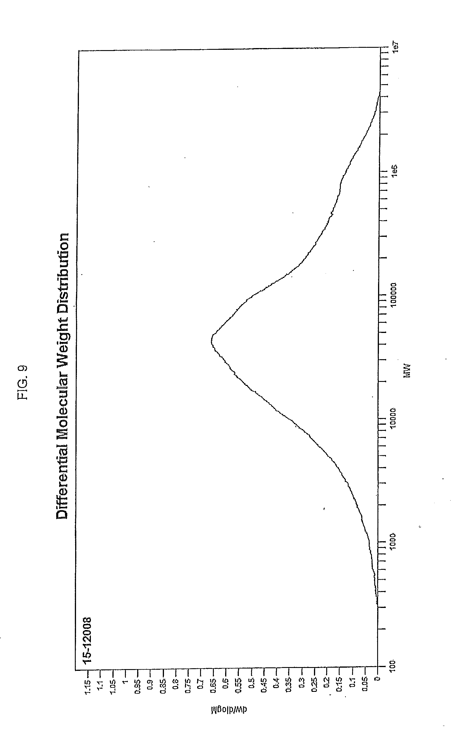
D00012
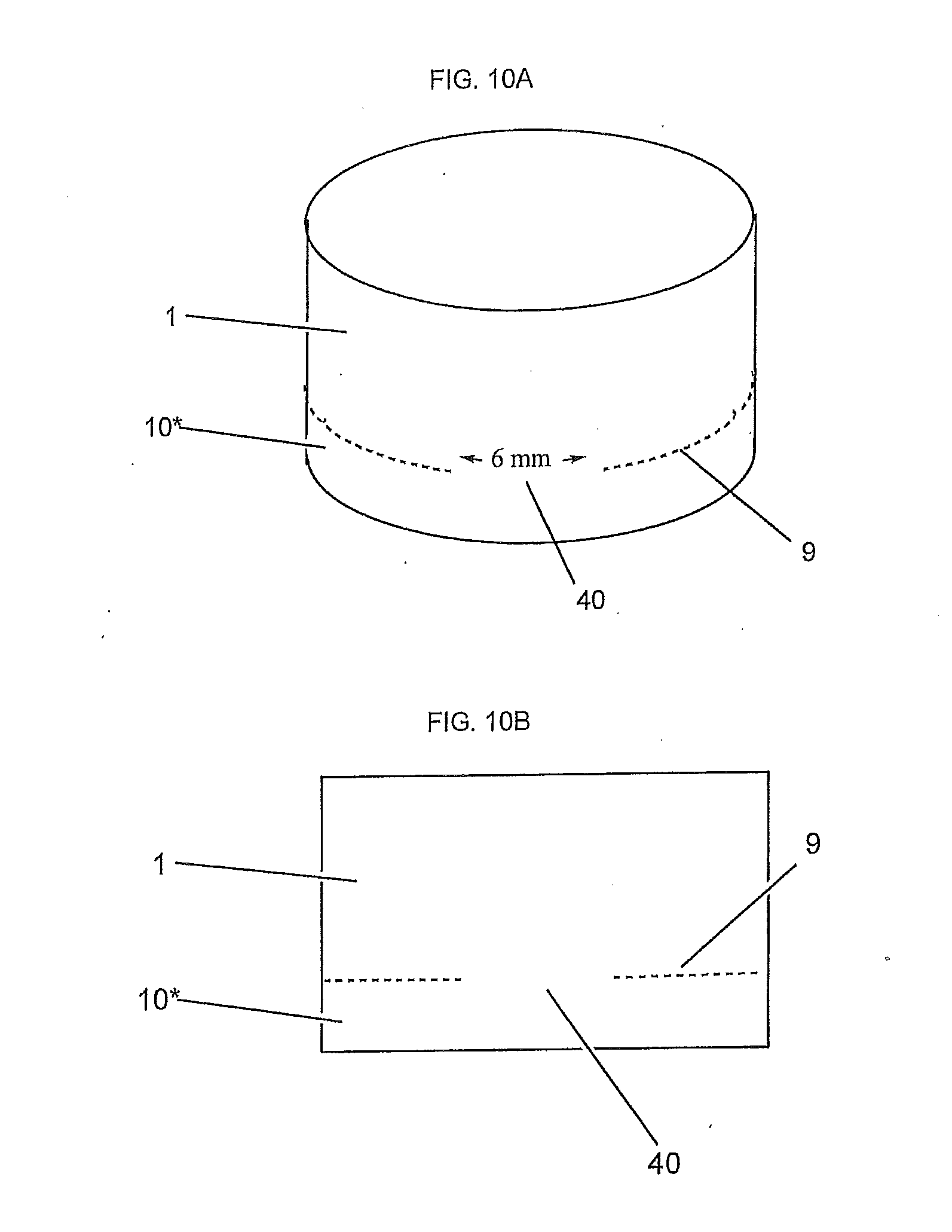
D00013

D00014
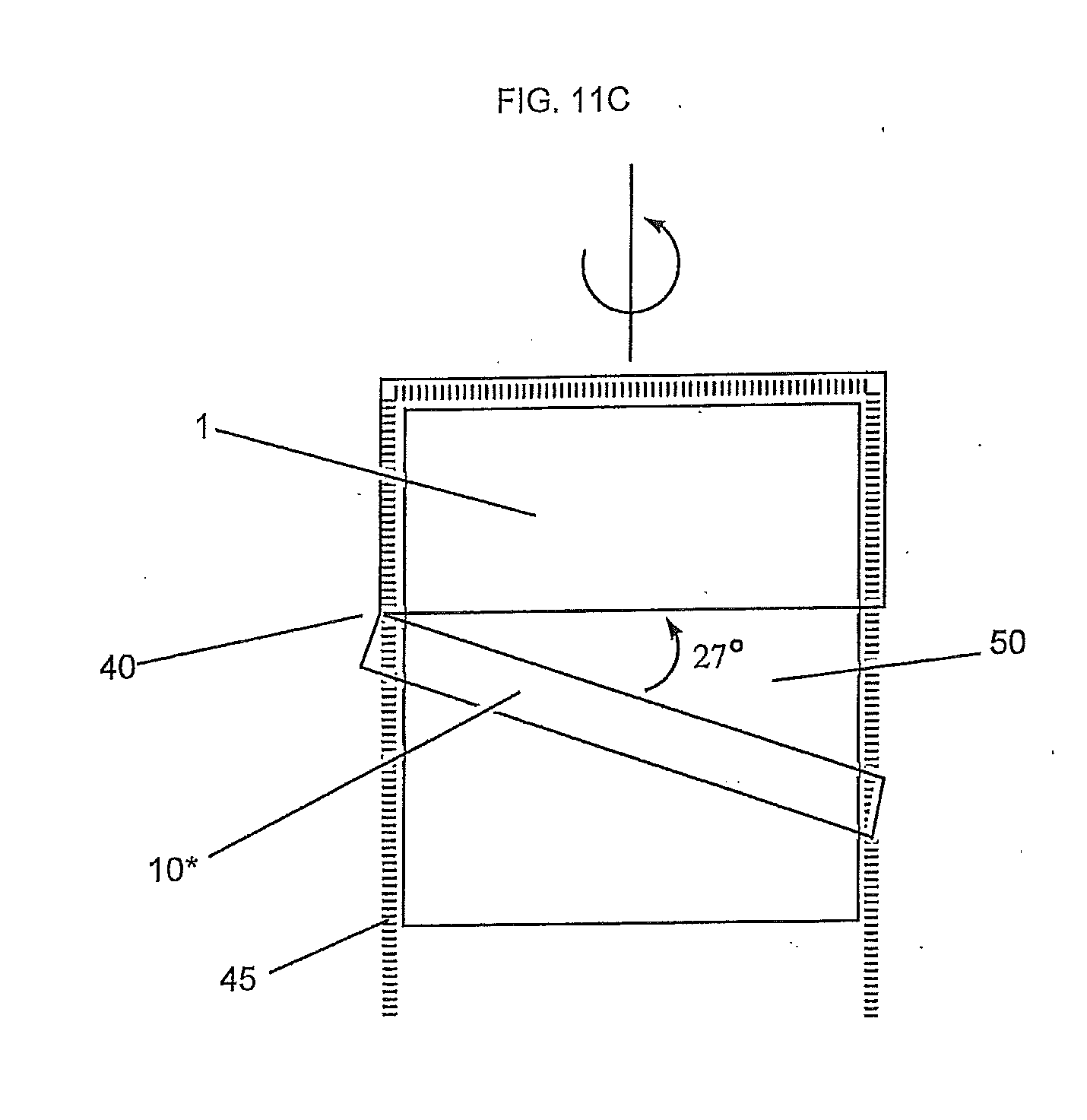
D00015

XML
uspto.report is an independent third-party trademark research tool that is not affiliated, endorsed, or sponsored by the United States Patent and Trademark Office (USPTO) or any other governmental organization. The information provided by uspto.report is based on publicly available data at the time of writing and is intended for informational purposes only.
While we strive to provide accurate and up-to-date information, we do not guarantee the accuracy, completeness, reliability, or suitability of the information displayed on this site. The use of this site is at your own risk. Any reliance you place on such information is therefore strictly at your own risk.
All official trademark data, including owner information, should be verified by visiting the official USPTO website at www.uspto.gov. This site is not intended to replace professional legal advice and should not be used as a substitute for consulting with a legal professional who is knowledgeable about trademark law.