Apparatus And Methods For Connecting Nodes To Tubes In Transport Structures
Kreig; Bill David ; et al.
U.S. patent application number 15/841857 was filed with the patent office on 2019-06-20 for apparatus and methods for connecting nodes to tubes in transport structures. The applicant listed for this patent is DIVERGENT TECHNOLOGIES, INC.. Invention is credited to Kevin Robert Czinger, Bill David Kreig, Narender Shankar Lakshman, Antonio Bernerd Martinez, Chukwubuikem Marcel Okoli, Broc William TenHouten, David Brian TenHouten.
| Application Number | 20190184465 15/841857 |
| Document ID | / |
| Family ID | 66814100 |
| Filed Date | 2019-06-20 |


| United States Patent Application | 20190184465 |
| Kind Code | A1 |
| Kreig; Bill David ; et al. | June 20, 2019 |
APPARATUS AND METHODS FOR CONNECTING NODES TO TUBES IN TRANSPORT STRUCTURES
Abstract
Apparatus and methods for joining nodes to tubes with node to tube joints are presented herein. Joining techniques allow the connection of additively manufactured nodes to tubes. In an embodiment, at least one node may be joined to a tube and may be a part of a vehicle chassis. The node to tube joint connection incorporates adhesive bonding between the node to tube to realize the connection. Sealants may be used to provide sealed regions for adhesive injection, which are housed in sealing interfaces co-printed with the additively manufactured nodes. Additionally, seals may act as isolators and reduce galvanic corrosion.
| Inventors: | Kreig; Bill David; (Huntington Beach, CA) ; TenHouten; David Brian; (Los Angeles, CA) ; Okoli; Chukwubuikem Marcel; (Los Angeles, CA) ; Czinger; Kevin Robert; (Santa Monica, CA) ; TenHouten; Broc William; (Rancho Palos Verdes, CA) ; Martinez; Antonio Bernerd; (El Segundo, CA) ; Lakshman; Narender Shankar; (Torrance, CA) | ||||||||||
| Applicant: |
|
||||||||||
|---|---|---|---|---|---|---|---|---|---|---|---|
| Family ID: | 66814100 | ||||||||||
| Appl. No.: | 15/841857 | ||||||||||
| Filed: | December 14, 2017 |
| Current U.S. Class: | 1/1 |
| Current CPC Class: | B29L 2031/265 20130101; B22F 5/106 20130101; B33Y 10/00 20141201; B33Y 80/00 20141201; B22F 3/1055 20130101 |
| International Class: | B22F 5/10 20060101 B22F005/10; B33Y 10/00 20060101 B33Y010/00; B33Y 80/00 20060101 B33Y080/00 |
Claims
1. An apparatus, comprising: a node comprising: a node wall having a perimeter; a first sealing interface around the perimeter, and a first adhesive path around the perimeter and bounded on a first side by the first sealing interface.
2. The apparatus of claim 1, further comprising a second sealing interface, the first adhesive path being bounded on a second side by the second sealing interface.
3. The apparatus of claim 2, wherein the first sealing interface, the second sealing interface, and the node wall form a first annular region.
4. The apparatus of claim 3, further comprising a port.
5. The apparatus of claim 4, wherein the port is an adhesive port directly connected to the first annular region.
6. The apparatus of claim 4, wherein the port is an outlet port directly connected to the first annular region.
7. The apparatus of claim 4, wherein the port is recessed.
8. The apparatus of claim 4, wherein the port protrudes.
9. The apparatus of claim 4, wherein the port is a hole.
10. The apparatus of claim 3, further comprising a tube, the first sealing interface, the second sealing interface, the node wall and a wall of the tube form a sealant chamber.
11. The apparatus of claim 1, wherein the first sealing interface comprises a mechanical seal.
12. The apparatus of claim 11, wherein the mechanical seal comprises at least one of an O-ring or a gasket.
13. The apparatus of claim 3, wherein the node further comprises a plurality of annular regions; wherein the plurality of annular regions comprises the first annular region; and wherein a width for at least one of the plurality of annular regions is based on an anticipated load of a connection between the node and a tube coupled to the node.
14. A method, comprising: manufacturing a node comprising: a node wall having a perimeter; a first sealing interface around the perimeter, and a first adhesive path around the perimeter and bounded on a first side by the first sealing interface.
15. The method of claim 14, further comprising manufacturing the node comprising a second sealing interface, the first adhesive path being bounded on a second side by the second sealing interface.
16. The method of claim 15, wherein the first sealing interface, the second sealing interface, and the node wall form a first annular region.
17. The method of claim 16, further comprising manufacturing the node comprising an adhesive port.
18. The method of claim 17, wherein the adhesive port is directly connected to the first annular region.
19. The method of claim 16, further comprising manufacturing the node comprising an outlet port.
20. The method of claim 19, wherein the outlet port is directly connected to the first annular region.
21. The method of claim 16, further comprising coupling a tube to the node, the first sealing interface, the second sealing interface, the node wall and the wall of the tube form a sealant chamber.
22. The method of claim 21, further comprising: drawing a vacuum to evacuate the sealant chamber; injecting an adhesive to create an adhesive fill; removing the vacuum following the adhesive fill; and removing the adhesive following the adhesive fill.
23. The method of claim 16, wherein the node further comprises a plurality of annular regions; wherein the plurality of annular regions comprise the first annular region; and wherein the method further comprises selecting a width for at least one of the plurality of annular regions based on an anticipated load of a connection between the node and a tube coupled to the node.
24. The method of claim 14, wherein the first sealing interface comprises a mechanical seal.
25. The method of claim 24, wherein the mechanical seal comprises at least one of an O-ring or a gasket.
26. The method of claim 14, wherein the manufacturing the node comprises additively manufacturing the node.
Description
BACKGROUND
Field
[0001] The present disclosure relates generally to techniques for joining nodes to tubes, and more specifically to joining nodes to tubes using additively manufactured parts.
Background
[0002] Recently three-dimensional (3D) printing, also referred to as additive manufacturing, has presented new opportunities to efficiently build parts for automobiles and other transport structures such as airplanes, boats, motorcycles, and the like. Applying additive manufacturing processes to industries that produce these products has proven to produce a structurally more efficient transport structure. An automobile produced using 3D printed components can be made stronger, lighter, and consequently, more fuel efficient. Furthermore, 3D printing of parts for automobiles can be more eco-friendly than conventional manufacturing techniques, as it does not significantly contribute to the burning of fossil fuels during the manufacturing process.
[0003] Automobiles and transport vehicles are constructed with panels, extrusions, nodes, and tubes. Conventional techniques for joining parts, such as welding, may not be a viable alternative to realize robust, multi-material, lightweight connections between components in a transport structure. Using additive manufacturing to fabricate nodes provides the opportunity to obtain successful connections between nodes and tubes, panels, extrusions, other standardized components, and other additively manufactured nodes. Accordingly, there is a need to discover and develop new ways to join tubes to nodes using additively manufactured parts and techniques.
SUMMARY
[0004] Several aspects of techniques for joining nodes to tubes using node to tube joints will be described more fully hereinafter with reference to three-dimensional (3D) printing techniques.
[0005] In one aspect an apparatus comprises a node. The node comprises a node wall, a first sealing interface, and a first adhesive path. The node wall has a perimeter. The first sealing interface is around the perimeter. The first adhesive path is around the perimeter and bounded on a first side by the first sealing interface.
[0006] The apparatus can further comprise a second sealing interface; and the first adhesive path can be bounded on a second side by the second sealing interface. The first sealing interface, the second sealing interface, and the node wall can form a first annular region.
[0007] The apparatus can further comprise a port. The port can be an adhesive port directly connected to the first annular region.
[0008] The port can be an outlet port directly connected to the first annular region.
[0009] The port can be recessed. The port can be protruding. The port can be a hole.
[0010] The apparatus can further comprise a tube. The first sealing interface, the second sealing interface, the node wall, and a wall of the tube can form a sealant chamber.
[0011] The first sealing interface can comprise a mechanical seal. The mechanical seal can comprise at least one of an O-ring or a gasket.
[0012] The node can further comprise a plurality of annular regions. The plurality of annular regions can comprise the first annular region. A width for at least one of the plurality of annular regions can be based on an anticipated load of a connection between the node and a tube coupled to the node.
[0013] In another aspect a method comprises manufacturing a node. The node comprises a node wall, a first sealing interface, and a first adhesive path. The node wall has a perimeter. The first sealing interface is around the perimeter. The first adhesive path is around the perimeter and bounded on a first side by the first sealing interface.
[0014] The method can further comprise manufacturing the node to comprise a second sealing interface. The first adhesive path can be bound on a second side by the second sealing interface. The first sealing interface, the second sealing interface, and the node wall can form a first annular region.
[0015] The method can further comprise manufacturing the node to include an adhesive port. The adhesive port can be directly connected to the first annular region.
[0016] The method can further comprise manufacturing the node to include an outlet port. The outlet port can be directly connected to the first annular region.
[0017] The method can further comprise coupling a tube to the node. The first sealing interface, the second sealing interface, the node wall, and a wall of the tube can form a sealant chamber.
[0018] The method can further comprise drawing a vacuum to evacuate the sealant chamber. The method can further comprise injecting an adhesive to create an adhesive fill. The method can further comprise removing the vacuum following the adhesive fill. The method can further comprise removing the adhesive following the adhesive fill.
[0019] The node can further comprise a plurality of annular regions. The plurality of annular regions can comprise the first annular region; and the method can further comprise selecting a width for at least one of the plurality of annular regions based on an anticipated load of a connection between the node and a tube coupled to the node.
[0020] The first sealing interface can comprise a mechanical seal. The mechanical seal can comprise at least one of an O-ring or a gasket. Manufacturing the node can comprise additively manufacturing the node.
[0021] It will be understood that other aspects of joining nodes to tubes using node to tube joints will become readily apparent to those skilled in the art from the following detailed description, wherein it is shown and described only several embodiments by way of illustration. As will be appreciated by those skilled in the art, the joining of nodes to tubes using additively manufactured parts can be realized with other embodiments without departing from the invention. Accordingly, the drawings and detailed description are to be regarded as illustrative in nature and not as restrictive.
BRIEF DESCRIPTION OF THE DRAWINGS
[0022] Various aspects of apparatus and methods for joining nodes to tubes with node to tube joints will now be presented in the detailed description by way of example, and not by way of limitation, in the accompanying drawings, wherein:
[0023] FIG. 1 illustrates a node attachment with adhesive paths according to an embodiment.
[0024] FIG. 2 illustrates a cross-sectional view of a node to tube joint according to an embodiment.
[0025] FIG. 3A illustrates a cross-sectional view of the node to tube joint showing an adhesive fill region according to a first part of a sequence.
[0026] FIG. 3B illustrates a cross-sectional view of the node to tube joint showing an adhesive fill region according to a second part of a sequence.
[0027] FIG. 3C illustrates a cross-sectional view of the node to tube joint showing an adhesive fill region according to a third part of a sequence.
[0028] FIG. 3D illustrates a cross-sectional view of the node to tube joint showing an adhesive fill region according to a fourth part of a sequence.
[0029] FIG. 3E illustrates a cross-sectional view of the node to tube joint showing an adhesive fill region according to a fifth part of a sequence.
[0030] FIG. 3F illustrates a cross-sectional view of the node to tube joint showing an adhesive fill region according to a sixth part of a sequence.
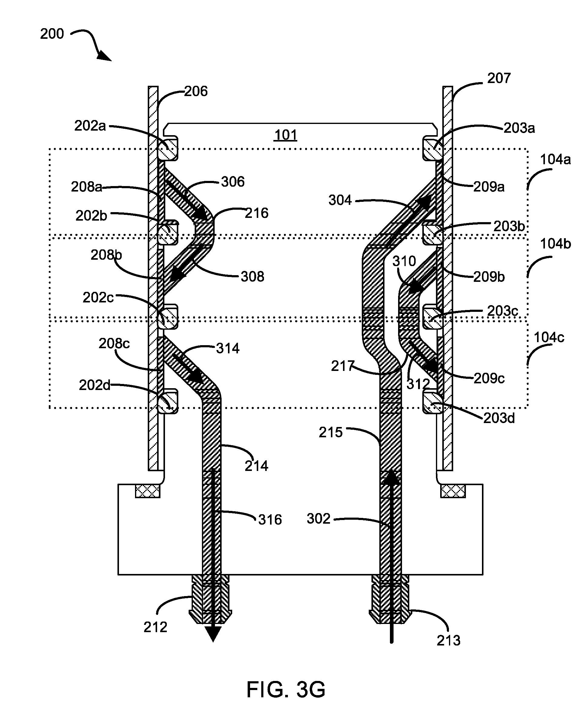
[0031] FIG. 3G illustrates a cross-sectional view of the node to tube joint showing an adhesive fill region according to a seventh part of a sequence.
[0032] FIG. 4 illustrates a conceptual flow diagram for connecting a tube to a node using node to tube joints according to an embodiment.
DETAILED DESCRIPTION
[0033] The detailed description set forth below in connection with the drawings is intended to provide a description of exemplary embodiments of joining additively manufactured nodes and tubes, and it is not intended to represent the only embodiments in which the invention may be practiced. The term "exemplary" used throughout this disclosure means "serving as an example, instance, or illustration," and should not necessarily be construed as preferred or advantageous over other embodiments presented in this disclosure. The detailed description includes specific details for the purpose of providing a thorough and complete disclosure that fully conveys the scope of the invention to those skilled in the art. However, the invention may be practiced without these specific details. In some instances, well-known structures and components may be shown in block diagram form, or omitted entirely, in order to avoid obscuring the various concepts presented throughout this disclosure.
[0034] The use of additive manufacturing in the context of joining two or more parts provides significant flexibility and cost saving benefits that enable manufacturers of mechanical structures and mechanized assemblies to manufacture parts with complex geometries at a lower cost to the consumer. The joining techniques described in the foregoing relate to a process for connecting additively manufactured parts and/or commercial off the shelf (COTS) components, also referred to as standardized components. Multi-material connections can be realized using additively manufactured components to provide robust isolation and by preventing physical contact between dissimilar materials, thereby preventing galvanic corrosion. Additively manufactured parts are printed three-dimensional (3D) parts that are printed by adding layer upon layer of a material based on a preprogramed design. The parts described in the foregoing may be parts used to assemble a transport structure such as an automobile. However, those skilled in the art will appreciate that the manufactured parts may be used to assemble other complex mechanical products such as vehicles, trucks, trains, motorcycles, boats, aircraft, and the like without departing from the scope of the invention.
[0035] Additive manufacturing provides the ability to create complex structures within a part. For example, a node is a structural member that may include one or more interfaces used to connect to other spanning components such as tubes, extrusions, panels, and the like. Using additive manufacturing, a node may be constructed to include additional features and functions, depending on the objectives. For example, a node may be printed with one or more ports that enable the node to secure two parts by injecting an adhesive rather than welding multiple parts together, as is traditionally done in manufacturing complex products. Alternatively, some components may be connected using a brazing slurry, a thermoplastic, a thermoset, or another connection feature, any of which can be used interchangeably in place of an adhesive. Thus, while welding techniques may be suitable with respect to certain additive manufacturing embodiments, additive manufacturing provides significant flexibility in enabling the use of alternative or additional connection techniques.
[0036] As described above, these are non-traditional approaches to connecting additively manufactured components and it can be advantageous to develop new ways to join components together during the manufacturing process. Joining nodes to tubes may incorporate one or more factors such as materials, structure, design, and/or connecting features. Additionally, a variety of tubes, including metal and alloy tubes, may be used in the teachings herein. Tubes may comprise a variety of different materials. For instance, as one of ordinary skill in the art can appreciate, tubes may comprise materials such as fiber reinforced composite, glass fiber reinforced polymer composite, thermoplastic, thermoset materials, and the like. In addition, tubes may be manufactured via a variety of manufacturing processes.
[0037] Apparatus and methods for joining nodes to tubes with node to tube joints are presented herein. Joining techniques allow the connection of additively manufactured nodes to tubes. In an embodiment, at least one node may be joined to a tube and may be a part of a vehicle chassis. The node to tube joint connection incorporates adhesive bonding between the node to tube to realize the connection. Sealants may be used to provide sealed regions to contain the flow of adhesive within defined regions during adhesive injection and to keep the regions clear from foreign substances. Additionally, sealants may act as isolators and reduce galvanic corrosion by preventing physical contact between the dissimilar materials being connected.
[0038] The node to tube connections described herein may be used as part of a vehicle chassis. An adhesive can be used between the node and tube to realize a node to tube connection. Sealants can be used to provide sealed regions for adhesive injection. Additionally, sealants can act as isolators to prevent potential galvanic corrosion, as noted above. The sealants can ensure that the adhesive regions are hermetically sealed such that contamination by foreign and/or environmental agents is prevented. Also, by using additively manufactured nodes, tooling costs and lead times can be reduced.
[0039] FIG. 1 illustrates a node attachment 100 according to an embodiment. The node attachment 100 includes a node 101 with adhesive paths 104a-c attached to a base 106 and sealant interfaces 102a-d. In the disclosure herein, sealant interfaces 102a-d may also be referred to as sealant grooves, sealing grooves, and/or sealing interfaces. As shown, the sealant interfaces 102a-d separate the adhesive paths 104a-c. The sealant interfaces 102a-d can house O-rings or, in other configurations the grooves 102a-d may include other types of sealants. The node 101 can be additively manufactured to include the sealant interfaces 102a-d. The base 106 As will be shown in FIG. 2, the node can also incorporate adhesive injection port(s) and/or other port(s). An outlet port can be used to attach a vacuum for drawing the adhesive and/or to function as a flow outlet port. In certain embodiments, the node 101 can include ports, which can be formed as recesses and/or holes instead of protrusions.
[0040] Although FIG. 1 illustrates the node attachment 100 as using a node 101 with three adhesive paths 104a-c attached to a base 106 and separated by sealant interfaces 102a-102d, other node configurations are possible. For instance, in some embodiments a node can have greater or fewer adhesive paths with greater or fewer sealant interfaces. In other embodiments, nodes may incorporate additional, potentially sophisticated, functions or structural features, whether at a surface of the node or integrated within the node. Also, in other embodiments the base 106 can have different shapes other than that shown. For instance, instead of having a hexagonal shape, the base 106 can have a circular or rectangular shape. Similarly, the remainder of the node can have any number of different possible shapes and configurations.
[0041] Also, although FIG. 1 illustrates a node attachment 100 having a round profile applicable to attaching a tube with a circular cross section, other embodiments are possible. For instance, instead of having a round profile, the node attachment 100 could have a rectangular, hexagonal, and/or square profile. In this way tubes with circular, rectangular, hexagonal, and/or square cross sections could be connected using the methods presented herein.
[0042] FIG. 2 illustrates a cross-sectional view of a node to tube joint 200 according to an embodiment. The node to tube joint 200 includes the node 101 surrounded by a tube 206. As in FIG. 1, the node 101 is partitioned into three adhesive paths 104a-c. Adhesive path 104a is partitioned between sealant interfaces 102a and 102b. Adhesive path 104b is partitioned between sealant interfaces 102b and 102c; and adhesive path 104c is partitioned between sealant interfaces 102c and 102d. O-rings 202a-202d are placed within sealant interfaces 102a-d to separate and allow the formation of seals within each of the three adhesive paths 104a-c. As shown in FIG. 2, O-ring 202a is placed in sealant interface 102a. O-ring 202b is placed in sealant interface 102b. O-ring 202c is placed in sealant interface 102c; and O-ring 202d is placed in sealant interface 102d. Due to the cross-sectional view of FIG. 2, the O-rings 202a-d, while four circular rings in reality, each appear as two distinct segments on respective sides of the tube 206, and like the tube 206 itself, the O-rings 202a-d are essentially protruding out of the plane of the drawing, above which would they curve in and meet to form the circular structure. Additionally, the sealant interfaces 102a-d can be printed as grooves which, in turn, can advantageously be used for holding the O-rings 202a-202d.
[0043] The node 101 also includes adhesive channels 214, 215, 216, and 217 which are positioned to allow a closed adhesive flow path between an external port 212 and an external port 213. The adhesive channels can also enable sequential flow of the adhesive into specific adhesive paths between the outer surface of the node and the inner surface of the tube, i.e. 104a, 104b, 104c.
[0044] As shown in FIG. 2, the adhesive channels 214, 215, 216, and 217 may connect into the sealant chambers 208a-c and 209a-c via ports 1A, 1B, 2A, 2B, 3A, and 3B. For instance, adhesive channel 215 connects into sealant chamber 209a via the port 1A; also adhesive channel 216 connects into sealant chamber 208a via the port 1B and into the port 208b via the port 2A. The ports 1A, 1B, 2A, 2B, 3A, and 3B can be holes, and the holes can be tapped, pressed, and/or threaded. Using tapped, pressed, and/or threaded holes as ports can advantageously reduce weight, although other implementations may be equally suitable.
[0045] Additionally, in some embodiments protruding ports can be used and the ports can be fabricated as breakaway ports. Breakaway ports allow for easy port removal after completion of a bonding process, which would advantageously result in mass savings. The adhesive channel may be a part of the node and can be additively manufactured. In other embodiments adhesive, outlet, and/or vacuum ports may be located on a base, such as base 106, and the location may be adjusted, for ease of port accessibility during assembly and adhesive injection.
[0046] As described herein, ports 1A and 1B are ports for channels in adhesive path 104a, ports 2A and 2B are ports for channels in adhesive path 104b, and ports 3A and 3B are ports for channels in adhesive path 104c. These ports may be holes. In the embodiment of FIG. 2, port 1A can be the end of the adhesive channel 215. Adhesive can exit through port 1A, and the vacuum can draw the adhesive into the adhesive path 104a. Once the adhesive has filled the adhesive path 104a completely, it can exit the region through port 1B. The adhesive can then be drawn into the adhesive path 104b via port 2A. Similar to the previous step in the sequence, it can exit the adhesive path 104b through port 2B. The sequence proceeds to fill the adhesive path 104b, wherein adhesive can enter the adhesive path 104c through port 3A. Once a complete fill is realized, the adhesive can exit the adhesive path 104c through Port 3B, and can proceed to the external port 212 (e.g. the outlet port).
[0047] In generating a vacuum, the vacuum is drawn first to evacuate the chambers (eg. chambers 208a-c, 209a-c). Once the chambers are evacuated, then a vacuum connection can be maintained, and the adhesive injection may commence. The vacuum connection can be retained until a complete fill of the adhesive is realized; once the adhesive fill is complete, then both the vacuum and adhesive connections can be disconnected.
[0048] Adhesive channel 214 connects between the external port 212 and a sealant chamber 208c between O-ring 202c and O-ring 202d. In this way the tube 214 provides an adhesive flow path between the sealant chamber 208c and the external port 212. The (closed) adhesive flow path continues from sealant chamber 208c to a sealant chamber 209c via the surface of node 101 in adhesive path 104c.
[0049] Adhesive channel 217 connects between the sealant chamber 209c and a sealant chamber 209b. As shown, sealant chamber 209c is between O-rings 202c and 202d; and sealant chamber 209b is between O-rings 202b and 202c. The adhesive channel 217 continues the adhesive flow path between sealant chamber 209c and sealant chamber 209b. The adhesive flow path continues from sealant chamber 209b to a sealant chamber 208b via the surface of node 101 in adhesive path 104b.
[0050] Adhesive channel 216 connects between the sealant chamber 208b and a sealant chamber 208a. As shown, sealant chamber 208b is between O-rings 202c and 202b; and sealant chamber 208a is between O-rings 202a and 202b. The adhesive channel 216 continues the adhesive flow path between sealant chamber 208b and sealant chamber 208a. The adhesive flow path continues from sealant chamber 208a to a sealant chamber 209a via the surface of node 101 in adhesive path 104a. Adhesive channel 215 connects between the external port 213 and the sealant chamber 209a between O-ring 202a and O-ring 202b. In this way the adhesive channel 215 continues the adhesive flow path between the sealant chamber 209a and the external port 213.
[0051] FIGS. 3A-3G illustrate cross-sectional views of the node to tube joint showing an adhesive fill region according to a sequence of drawing an adhesive. The adhesive can be drawn by using the closed path formed with the adhesive channels 214, 215, 216, and 217. In an embodiment, adhesive can be applied through port 213 and a vacuum can be drawn at port 212 to cause adhesive to follow the sequence discussed below.
[0052] FIG. 3A illustrates a cross-sectional view of the node to tube joint 200 showing an adhesive fill region according to a first part of the sequence. Adhesive is injected via port 213 along adhesive flow vectors 302 and 304 through adhesive channel 215 into the sealant chamber 209a. As shown in FIG. 3A, during the first part of the sequence the adhesive flow fills the sealant chamber 209a.
[0053] FIG. 3B illustrates a cross-sectional view of the node to tube joint 200 showing an adhesive fill region according to a second part of the sequence. Adhesive continues flowing from the sealant chamber 209a to the sealant chamber 208a via the surface of node 101 in adhesive path 104a. As shown in FIG. 3B, during the second part of the sequence the adhesive flow fills the sealant chamber 208a.
[0054] FIG. 3C illustrates a cross-sectional view of the node to tube joint 200 showing an adhesive fill region according to a third part of the sequence. Adhesive continues flowing along adhesive flow vectors 306 and 308 through adhesive channel 216 from the sealant chamber 208a to the sealant chamber 208b. As shown in FIG. 3C, during the third part of the sequence the adhesive flow fills the sealant chamber 208b.
[0055] FIG. 3D illustrates a cross-sectional view of the node to tube joint 200 showing an adhesive fill region according to a fourth part of the sequence. Adhesive continues flowing from the sealant chamber 208b to the sealant chamber 209b via the surface of node 101 in adhesive path 104b. As shown in FIG. 3D, during the fourth part of the sequence the adhesive flow fills the sealant chamber 209b.
[0056] FIG. 3E illustrates a cross-sectional view of the node to tube joint 200 showing an adhesive fill region according to a fifth part of the sequence. Adhesive continues flowing along adhesive flow vectors 310 and 312 through adhesive channel 217 from the sealant chamber 209b to the sealant chamber 209c. As shown in FIG. 3E, during the fifth part of the sequence the adhesive flow fills the sealant chamber 209c.
[0057] FIG. 3F illustrates a cross-sectional view of the node to tube joint 200 showing an adhesive fill region according to a sixth part of the sequence. Adhesive continues flowing from the sealant chamber 209c to the sealant chamber 208c via the surface of node 101 in adhesive path 104c. The adhesive channel 316 pulls adhesive from the sealant chamber 209c to the sealant chamber 208c as indicated by the adhesive flow vectors 314 and 316. As shown in FIG. 3F, during the sixth part of the sequence the adhesive flow fills the sealant chamber 208c.
[0058] FIG. 3G illustrates a cross-sectional view of the node to tube joint 200 showing an adhesive fill region according to a seventh part of a sequence. Once adhesive has filled the regions between ports 212 and 213 completely as shown in FIG. 3G, the node to tube joint 200 can undergo curing. As one of ordinary skill in the art can appreciate, the curing cycle can be selected based on the adhesive type.
[0059] The node 101 may be designed to have a variety of hollow sections to reduce the weight of the part. In an embodiment, the node may be designed and additively manufactured such that its center is substantially hollow. The geometry of the node 101 may have a variety of structural shapes allowing it to be robust and lightweight.
[0060] FIG. 4 illustrates a conceptual flow diagram for connecting a tube to a node using node to tube joints according to an embodiment. In the first step 402, a node (e.g. node 101) is additively manufactured. The node comprises an adhesive port, vacuum port, sealing interfaces, and adhesive channels. In next step 404, seals, such as O-rings, are installed in sealing interfaces on the node. In the following step 406, a tube is introduced. The tube and node are assembled with the installed seals to obtain sealant chambers. The sealant chambers are between the node wall(s) and tube wall(s) as depicted in FIGS. 3A-3G. The sealant chambers are bound by the seals (e.g. O-rings) installed in the sealing interfaces. Next in step 408 a vacuum is drawn through the vacuum port while the adhesive is injected through the adhesive port to fill the sealant chambers with adhesive. Finally, in step 410 a curing cycle, appropriate to the type of adhesive, is selected to cure the adhesive.
[0061] Seals can be applied to the sealing interfaces after the node is additively manufactured, and after all the prerequisite post processing operations are performed. Once the seals are applied at the sealing interfaces, the node can be assembled with the tube. The seals housed in the sealing interfaces can provide the required seals for the sealing chambers. Once this is done, a vacuum can be drawn, and adhesive can be injected. The adhesive can flow into the sealant chambers and also into a plurality of adhesive annular regions.
[0062] The above process can also be automated and a complete fill of adhesive may be monitored through a variety of ways: For instance, a vacuum pressure during the adhesive flow process may be monitored and may be indicative of a complete adhesive fill. Alternatively and additionally, a volume of the adhesive being injected may be monitored; it may be determined that the fill is complete once the appropriate amount of adhesive has been injected into the assembly. Also, automated assembly systems may incorporate vision systems to image adhesive flow out of and/or into the vacuum port to determine when the adhesive fill process is complete. In some embodiments not using vacuum connections, positive injection pressure of adhesive injection would be sufficient to evacuate the chambers, and inject adhesive into the chambers. The adhesive would flow out of the outlet port, indicating a complete fill.
[0063] The previous description is provided to enable any person skilled in the art to practice the various aspects described herein. Various modifications to these exemplary embodiments presented throughout this disclosure will be readily apparent to those skilled in the art, and the concepts disclosed herein may be applied to other techniques for printing and joining nodes and tubes with node to tube joints. Thus, the claims are not intended to be limited to the exemplary embodiments presented throughout the disclosure, but are to be accorded the full scope consistent with the language claims. All structural and functional equivalents to the elements of the exemplary embodiments described throughout this disclosure that are known or later come to be known to those of ordinary skill in the art are intended to be encompassed by the claims. Moreover, nothing disclosed herein is intended to be dedicated to the public regardless of whether such disclosure is explicitly recited in the claims. No claim element is to be construed under the provisions of 35 U.S.C. .sctn. 112(f), or analogous law in applicable jurisdictions, unless the element is expressly recited using the phrase "means for" or, in the case of a method claim, the element is recited using the phrase "step for."
* * * * *
D00000
D00001
D00002
D00003
D00004
D00005
D00006
D00007
D00008
D00009
D00010
XML
uspto.report is an independent third-party trademark research tool that is not affiliated, endorsed, or sponsored by the United States Patent and Trademark Office (USPTO) or any other governmental organization. The information provided by uspto.report is based on publicly available data at the time of writing and is intended for informational purposes only.
While we strive to provide accurate and up-to-date information, we do not guarantee the accuracy, completeness, reliability, or suitability of the information displayed on this site. The use of this site is at your own risk. Any reliance you place on such information is therefore strictly at your own risk.
All official trademark data, including owner information, should be verified by visiting the official USPTO website at www.uspto.gov. This site is not intended to replace professional legal advice and should not be used as a substitute for consulting with a legal professional who is knowledgeable about trademark law.