Semi-solid Slurry Generator And High Pressure Die Casting Method
BAEK; Un Cheol
U.S. patent application number 16/099568 was filed with the patent office on 2019-06-20 for semi-solid slurry generator and high pressure die casting method. The applicant listed for this patent is DTR CO., LTD.. Invention is credited to Un Cheol BAEK.
| Application Number | 20190184457 16/099568 |
| Document ID | / |
| Family ID | 60326269 |
| Filed Date | 2019-06-20 |


View All Diagrams
| United States Patent Application | 20190184457 |
| Kind Code | A1 |
| BAEK; Un Cheol | June 20, 2019 |
SEMI-SOLID SLURRY GENERATOR AND HIGH PRESSURE DIE CASTING METHOD
Abstract
Disclosed are a semi-solid slurry generator and a die casting method which can obtain a dense structure in the entire cross section of a molded product by uniformly dispersing and stirring an inert gas in a slurry compared to a conventional one. The die casting method comprises: a step of immersing a rotating diffuser in a molten metal contained in a ladle to rotate and stir the molten metal while being supplied with an inert gas, or rotating and stirring the molten metal and the inert gas, which are sucked into a pumping impeller, while being ejected through a hole provided on a side surface of the impeller by stirring the same, such that the molten metal is cooled while gas bubbles caused by the inert gas are uniformly dispersed in the molten metal, thereby forming a semi-solid slurry; and a step of pressurizing and injecting the semi-solid slurry into a mold of a molding machine.
| Inventors: | BAEK; Un Cheol; (Gyeongsangnam-do, KR) | ||||||||||
| Applicant: |
|
||||||||||
|---|---|---|---|---|---|---|---|---|---|---|---|
| Family ID: | 60326269 | ||||||||||
| Appl. No.: | 16/099568 | ||||||||||
| Filed: | May 16, 2017 | ||||||||||
| PCT Filed: | May 16, 2017 | ||||||||||
| PCT NO: | PCT/KR2017/005076 | ||||||||||
| 371 Date: | November 7, 2018 |
| Current U.S. Class: | 1/1 |
| Current CPC Class: | B22D 17/007 20130101; B22D 1/005 20130101; B22D 17/32 20130101; B22D 17/10 20130101; B22D 1/002 20130101; B22D 21/04 20130101 |
| International Class: | B22D 17/32 20060101 B22D017/32; B22D 21/04 20060101 B22D021/04; B22D 1/00 20060101 B22D001/00; B22D 17/00 20060101 B22D017/00 |
Foreign Application Data
| Date | Code | Application Number |
|---|---|---|
| May 17, 2016 | KR | 10-2016-0060437 |
Claims
1. A semi-solid slurry generator for generating a semi-solid slurry by supplying an inert gas to a molten metal contained in a ladle, the semi-solid slurry generator comprising: a diffuser for supplying the inert gas into the molten metal in a state of being immersed in the molten metal contained in the ladle; an inert gas supply unit for supplying the inert gas to the diffuser; a rotation support to rotatably support the diffuser; a rotation unit configured to rotate the diffuser; a slide guide to guide upward and downward movements of the rotation support; a lifting unit configured to move the rotation support up and down along the slide guide; and a guide support unit to support the slide guide.
2. The semi-solid slurry generator of claim 1, wherein the diffuser includes a porous impeller having an empty space configured to accommodate the inert gas supplied from the inert gas supply unit and a plurality of pores so as to disperse and supply the inert gas supplied into the empty space.
3. The semi-solid slurry generator of claim 1, wherein the diffuser includes a pumping impeller including a hollow portion communicating with the inert gas supply unit and having an open lower portion and a lateral hole formed in a side surface and communicating with the hollow portion inside, and wherein the pumping impeller has a pumping function of rotationally stirring the molten metal while rotating stirring the inert gas supplied from the inert gas supply unit and the molten metal sucked into the hollow portion from the opened lower portion of the hollow portion and ejecting the molten metal through the lateral hole by a centrifugal force.
4. The semi-solid slurry generator of claim 1, wherein the guide support unit includes a post and a horizontal support unit connected to the slide guide and supported by the post, and the horizontal support unit is configured to be horizontally movable on the post, and the horizontal support unit is provided with a horizontal movement unit to horizontally move the horizontal support unit.
5. The semi-solid slurry generator of claim 1, further comprising: a control unit to control operations of the rotation unit and the lifting unit.
6. The semi-solid slurry generator of claim 1, wherein the diffuser includes grooves or protrusions, which are formed to be spaced apart from each other along an outer circumferential surface thereof so as to function as an impeller, or the diffuser is formed to have a polygonal cross section or is provided with an actual impeller so that the molten metal can be stirred and flowed well when the diffuser rotates (the impeller includes a diffuser-integrated impeller, a detachable impeller, and an impeller capable of pumping).
7. The semi-solid slurry generator of claim 1, wherein the diffuser is made of ceramic or graphite and is detachably attached to the head.
8. The semi-solid slurry generator of claim 4, the semi-solid slurry generator comprising: a control unit to control operations of the inert gas supply unit, the rotation unit, the lifting unit, and the horizontal movement unit, wherein the rotation support is provided with a temperature measuring unit to measure a temperature of the molten metal and to input an information of the measured temperature to the control unit.
9. The semi-solid slurry generator of claim 2, wherein the impeller diffuser has a cross section having a polygonal shape or a groove, a curved surface or a concavo-convex shape as a whole or in part such that the molten metal can be flowed and stirred well when the diffuser rotates.
10. The semi-solid slurry generator of claim 1, wherein the rotation support is provided with a baffle plate disposed apart from the diffuser so as to disturb rotation of the molten metal.
11. A die casting method comprising: a step of immersing a diffuser in a molten metal contained in a ladle and rotating the diffuser while supplying an inert gas so as to cause gas bubbles, which are formed by the inert gas, to be evenly dispersed and stirred in the molten metal, so that the molten metal is cooled to generate a semi-solid slurry; and a step of performing molding by pressurizing and injecting the semi-solid slurry into a mold of a molding machine.
12. The die casting method of claim 11, wherein the molten metal is a molten metal of an Al-alloy or Mg-alloy, and the inert gas is argon gas or nitrogen gas.
13. The die casting method of claim 11, wherein the semi-solid slurry is supplied to a plunger of the molding machine at a temperature, which is equal to or lower than a melting point of the metal.
14. The die casting method of claim 11, the die casting method comprising: a step of disturbing rotation of the molten metal by disposing a baffle plate in the ladle to be spaced apart from the diffuser.
15. The die casting method of claim 11, wherein a step of enhancing a rotational bubbling and stirring effect by disposing a baffle plate inside the ladle to be spaced apart from the diffuser.
16. The die casting method of claim 11, wherein the step of generating the semi-solid slurry is performed using a semi-solid slurry generator comprising: a diffuser for supplying the inert gas into the molten metal in a state of being immersed in the molten metal contained in the ladle; an inert gas supply unit for supplying the inert gas to the diffuser; a rotation support to rotatably support the diffuser; a rotation unit configured to rotate the diffuser; a slide guide to guide upward and downward movements of the rotation support; a lifting unit configured to move the rotation support up and down along the slide guide; and a guide support unit to support the slide guide.
17. The die casting method of claim 16, wherein the diffuser of the semi-solid slurry generator includes a porous impeller having an empty space configured to accommodate the inert gas supplied from the inert gas supply unit and a plurality of pores so as to disperse and supply the inert gas supplied into the empty space.
18. The die casting method of claim 16, wherein the diffuser of the semi-solid slurry generator includes a pumping impeller including a hollow portion communicating with the inert gas supply unit and having an open lower portion and a lateral hole formed in a side surface and communicating with the hollow portion inside, and wherein the pumping impeller has a pumping function of rotationally stirring the molten metal while rotating stirring the inert gas supplied from the inert gas supply unit and the molten metal sucked into the hollow portion from the opened lower portion of the hollow portion and ejecting the molten metal through the lateral hole by a centrifugal force.
19. The die casting method of claim 16, wherein the guide support unit of the semi-solid slurry generator includes a post and a horizontal support unit connected to the slide guide and supported by the post, and the horizontal support unit is configured to be horizontally movable on the post, and the horizontal support unit is provided with a horizontal movement unit to horizontally move the horizontal support unit.
20. The die casting method of claim 16, wherein the semi-solid slurry generator further comprises a control unit to control operations of the rotation unit and the lifting unit.
Description
TECHNICAL FIELD
[0001] The present disclosure relates to improvements of a non-dendritic semi-solid slurry generator and a die casting method or a production technology. More particularly, the present invention relates to an improvement of a semi-solid slurry generator for obtaining a homogeneous semi-solid slurry in which crystals are micronized by performing bubbling and cooling through a diffuser that is immersed in a molten metal contained in a ladle to blow an inert gas and breaking dendritic crystals, and an improvement of a high-pressure die casting method for obtaining a molded product having a dense structure by pouring a semi-solid slurry into a molding machine and pressurizing and solidifying the slurry within the mold.
BACKGROUND ART
[0002] International Publication WO 2007/09223 A2 (inventors: WANNASIN, Jessada et al.) discloses a molding method for obtaining a molded product having a dense structure by immersing a porous graphite diffuser in a molten metal contained in the ladle, introducing and bubbling an inert gas such as nitrogen or argon in the molten metal so as to turn the molten metal into a semi-solid slurry (a liquid molten metal including solid phase by about 10%), pouring the semi-solid slurry into a molding machine with high pressure, and cooling the semi-solid slurry within a mold. The disclosure disclosed in WO 2007/092203 A2 is a technique capable of providing a structure that is more dense than those in conventional die casting products molded using a general molten metal (100% liquid molten metal in a supersaturated state). The related art will be described with reference to FIGS. 1 and 2.
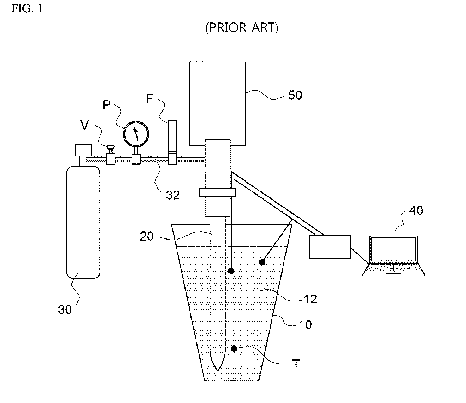
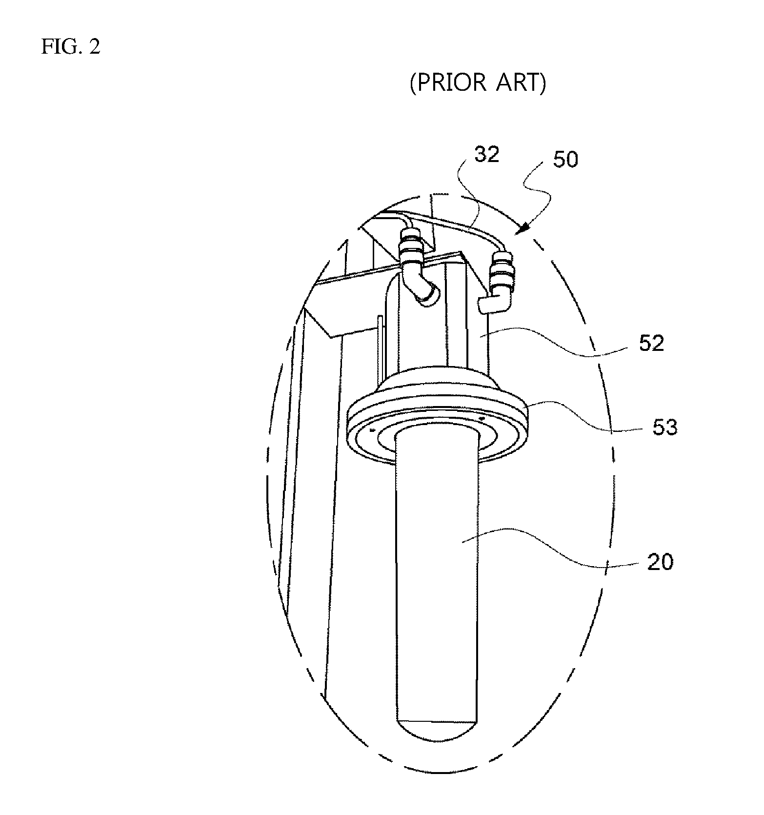
[0003] FIG. 1 is a view for explaining a conventional semi-solid slurry generation method by gas bubbling, and FIG. 2 is a view illustrating a mounting state of a conventional diffuser.
[0004] In the conventional semi-solid slurry generation method, in the state in which, a porous graphite diffuser 20 is lowered so as to be immersed in the molten metal 12 contained in the ladle 10, an inert gas, such as nitrogen or argon, which is stored in the gas container 30, is supplied into the molten metal 12 through the graphite diffuser 20 to cool the molten metal 12 while bubbling the inert gas in the molten metal 12 to obtain a semi-solid slurry. At this time, a temperature sensor T is disposed in the molten metal 12 to measure the temperature of the molten metal 12, and based on this, the quantity and the pressure of the inert gas supplied to the molten metal 12 on the basis thereof and the time for supplying the inert gas are adjusted by a control unit 40. A valve V, a pressure gauge P, a flow meter F, and the like are provided on an inert gas supply path such as a hose 32.
[0005] When it is determined that the molten metal 12 corresponds to a predetermined condition of a semi-solid state through data applied from the temperature sensor T, the control unit 40 moves up the graphite diffuser 20 to release the graphite diffuser 20 from the ladle 10 and stops gas supply. Through this process, the semi-solid slurry is generated.
[0006] However, in the prior art as described above, there is a problem in that, since the graphite diffuser 20 bubbles the inert gas in the molten metal 12 at a given pressure while maintaining the static state thereof, the inert gas is present only around the graphite diffuser 20, which makes it impossible to achieve uniform bubbling and micronizing of the entire molten metal 12.
[0007] That is, there is a problem in that, since a large amount of inert gas is present in the molten metal 12 around the graphite diffuser 20 and the inert gas bubbling effect does not occur in the molten metal 12 located far from the graphite diffuser 20, crystal grains cannot be properly micronized. A product made using a semi-solid slurry having such a problem has a problem in that mechanical properties such as strength are not uniform in respective portions.
[0008] In addition, the conventional graphite diffuser 20 used as a gas bubbling means has a cylindrical shape as illustrated in FIG. 2 and is fixed to a head 52 of a semi-solid slurry generator 50, which has a flange 53, through a plurality of bolts and nuts. Accordingly, it takes a long time to replace the graphite diffuser 20. The head 52 is installed so as to be moved up and down along a guide provided in the slurry generator 50, and the hose 32 is connected to the head 52 so as to supply an inert gas and air to the graphite diffuser 20.
[0009] That is, the conventional graphite diffuser 20 performs only a function of generating bubbles by receiving an inert gas and supplying the inert gas to the inside of the molten metal through pores.
[0010] The graphite diffuser 20 has a short lifetime due to hardening or the like, and has a problem in that a residual molten metal of an Al-alloy or the like adheres to the diffuser to block the pores, which causes the gas to be unevenly supplied to the entire molten metal. Alternatively, the residual molten metal, which has adhered to the diffuser, is mixed into the molten metal poured into a mold, making it difficult to produce homogeneous products. When a product is made using such a semi-solid slurry, a defect is generated therein.
DETAILED DESCRIPTION OF THE INVENTION
Technical Problem
[0011] An object of the present invention is to provide a semi-solid slurry generator and a die casting method, in which an inert gas is blown into a molten metal to be dispersed in a small bubble state and to bubble the molten metal, thereby breaking dendritic crystals so as to obtain a fine structure, thereby obtaining a dense structure in the entire cross section of a molded product.
[0012] Another object of the present invention is to provide a semi-solid slurry generator and a die casting method, in which a metal slurry or a molten metal of aluminum, an Al-alloy, an Mg-alloy, or the like hardly adheres, compared to the conventional porous graphite diffuser, thereby significantly reducing the possibility of causing product defects.
[0013] Still another object of the present invention is to provide a diffuser having a porous impeller, which can be suitably used in the die casting method of the present invention.
[0014] Still another object of the present invention is to provide a diffuser having a pumping impeller for improving stirring, which can be suitably used in the die casting method of the present invention.
[0015] Still another object of the present invention is to provide a semi-solid slurry generator including a porous diffuser impeller, which has a long lifespan and is easily replaceable.
[0016] Yet another object of the present invention is to provide a semi-solid slurry generator including a diffuser having a pumping impeller, which has a long lifespan and is easily replaceable.
[0017] Yet another object of the present invention is to provide a semi-solid slurry generator and a die casting method, which can be suitably utilized for making lightweight and high strength automobile components, such as an intermediate bracket of an automobile engine mount.
Technical Solution
[0018] The present invention provides a semi-solid slurry generator for generating a semi-solid slurry by supplying an inert gas to a molten metal contained in a ladle, in which the semi-solid slurry generator includes: a diffuser for supplying the inert gas into the molten metal in a state of being immersed in the molten metal contained in the ladle; an inert gas supply unit for supplying the inert gas to the diffuser; a rotation support to rotatably support the diffuser; a rotation unit configured to rotate the diffuser; a slide guide to guide upward and downward movements of the rotation support; a lifting unit configured to move the rotation support up and down along the slide guide; and a guide support unit to support the slide guide.
[0019] The diffuser may include a porous impeller having an empty space configured to accommodate the inert gas supplied from the inert gas supply unit and a plurality of pores so as to disperse and supply the inert gas supplied to the empty space.
[0020] In some cases, the diffuser may include a pumping impeller including a hollow portion communicating with the inert gas supply unit and having an open lower portion and a lateral hole formed in a side surface and communicating with the hollow portion inside, in which the pumping impeller has a pumping function of rotationally stirring the molten metal while rotating and stirring the inert gas supplied from the inert gas supply unit and the molten metal sucked into the opened hollow portion from the lower portion of the hollow portion and ejecting the molten metal through the lateral hole by a centrifugal force.
[0021] The guide support unit may include a post and a horizontal support unit connected to the slide guide and supported by the post,
[0022] and the horizontal support unit is configured to be horizontally movable on the post, and the horizontal support unit is provided with a horizontal movement unit to horizontally move the horizontal support unit.
[0023] The semi-solid slurry generator may further include a control unit to control operations of the rotation unit and the lifting unit.
[0024] The diffuser may include grooves or protrusions, which are formed to be spaced apart from each other along an outer circumferential surface thereof so as to function as an impeller, or the diffuser may be formed to have a polygonal cross section or may be provided with an actual impeller so that the molten metal can be stirred and flowed well when the diffuser rotates (the impeller includes a diffuser-integrated impeller, a detachable impeller, and an impeller capable of pumping).
[0025] The diffuser may be made of ceramic or graphite and may be detachably attached to the head.
[0026] The semi-solid slurry generator may include a control unit to control operations of the inert gas supply unit, the rotation unit, the lifting unit, and the horizontal movement unit, and the rotation support may be provided with a temperature measuring unit to measure a temperature of the molten metal and to input an information of the measured temperature to the control unit.
[0027] The impeller diffuser may have a cross section having a polygonal shape or a groove, a curved surface or a concavo-convex shape as a whole or in part such that the molten metal can be flowed and stirred well when the diffuser rotates.
[0028] The rotation support may be provided with a baffle plate disposed apart from the diffuser so as to disturb rotation of the molten metal.
[0029] A die casting method according to the present invention includes: a step of immersing a diffuser in a molten metal contained in a ladle and rotating the diffuser while supplying an inert gas so as to cause gas bubbles, which are formed by the inert gas, to be evenly dispersed and stirred in the molten metal, so that the molten metal is cooled to generate a semi-solid slurry; and a step of performing molding by pressurizing and injecting the semi-solid slurry into a mold of a molding machine.
[0030] The molten metal may be a molten metal of an Al-alloy or Mg-alloy, and the inert gas may be argon gas or nitrogen gas.
[0031] The semi-solid slurry may be supplied to a plunger of the molding machine at a temperature, which is equal to or lower than a melting point of the metal.
[0032] The die casting method may include a step of disturbing rotation of the molten metal by disposing a baffle plate in the ladle to be spaced apart from the diffuser.
[0033] The die casting method may include a step of enhancing a rotational bubbling and stirring effect by disposing a baffle plate inside the ladle to be spaced apart from the diffuser.
[0034] The step of generating the semi-solid slurry may be performed using the semi-solid slurry generator according to the present invention.
[0035] The semi-solid slurry obtained as described above is introduced into a molding machine and is pressurized and solidified inside the mold, thereby obtaining a molded product having a dense structure.
Advantageous Effects
[0036] According to the present invention, it is possible to obtain a dense structure in the entire cross section of a molded product, compared with a conventional molded product by causing an inert gas to be uniformly dispersed, bubbled, and stirred in the slurry.
[0037] Since the metal slurry of aluminum or the like hardly adheres to the ceramic diffuser according to the present invention compared with the conventional graphite diffuser, the ceramic diffuser according to the present invention is much less likely to cause a product defect and the ceramic diffuser according to the present invention has a long lifespan and is easily replaceable.
[0038] In addition, according to the method of the present invention, it is possible to improve quality by stabilizing sticking, scraps and hot zones, and lowering the temperature of the molten metal (suppressing bubbles and cracks due to fusion sticking), and to obtain excellent effects, such as an increase of the life span of a mold (estimated 1.5 times), a decrease of mold surface temperature, a reduction of thermal fatigue, a reduction of thermal shock, a reduction of the melting loss, etc. by lowering the temperature of the molten metal at the time of pouring the molten metal from the ladle to the plunger by 60.degree. C. or more (660.degree. C. (conventional)->590.degree. C. (improvement)).
[0039] According to the present invention, it is possible to obtain a semi-solid slurry having micronized crystals by immersing and rotating a porous impeller diffuser or a pumping impeller diffuser in the molten metal contained in the ladle, blowing an inert gas into the molten metal while rotating the diffuser so as to stir the molten metal vigorously while dispersing and bubbling the inert gas in the molten metal in a small bubble state, and cooling the molten metal and breaking dendritic crystals while bubbling the molten metal.
[0040] Particularly, since the pumping impeller diffuser has a function of rotationally stirring the molten metal and simultaneously ejecting the molten metal through the holes provided in the side surface by stirring the supplied inert gas and the molten metal sucked into the hollow portion through the opened lower portion of the hollow portion, the pumping impeller diffuser is excellent in the effect of uniformly distributing bubbles.
[0041] The semi-solid slurry obtained as described above is introduced into a molding machine and is pressurized and solidified inside the mold, thereby obtaining a molded product having a dense structure.
BRIEF DESCRIPTION OF THE DRAWINGS
[0042] FIG. 1 is a view for explaining a general semi-solid slurry generation method;
[0043] FIG. 2 is a view illustrating a mounting state of a conventional diffuser;
[0044] FIG. 3 is a photograph for explaining a semi-solid slurry generator according to the present invention;
[0045] FIG. 4 is a view for explaining the internal configuration of the semi-solid slurry generator according to the present invention;
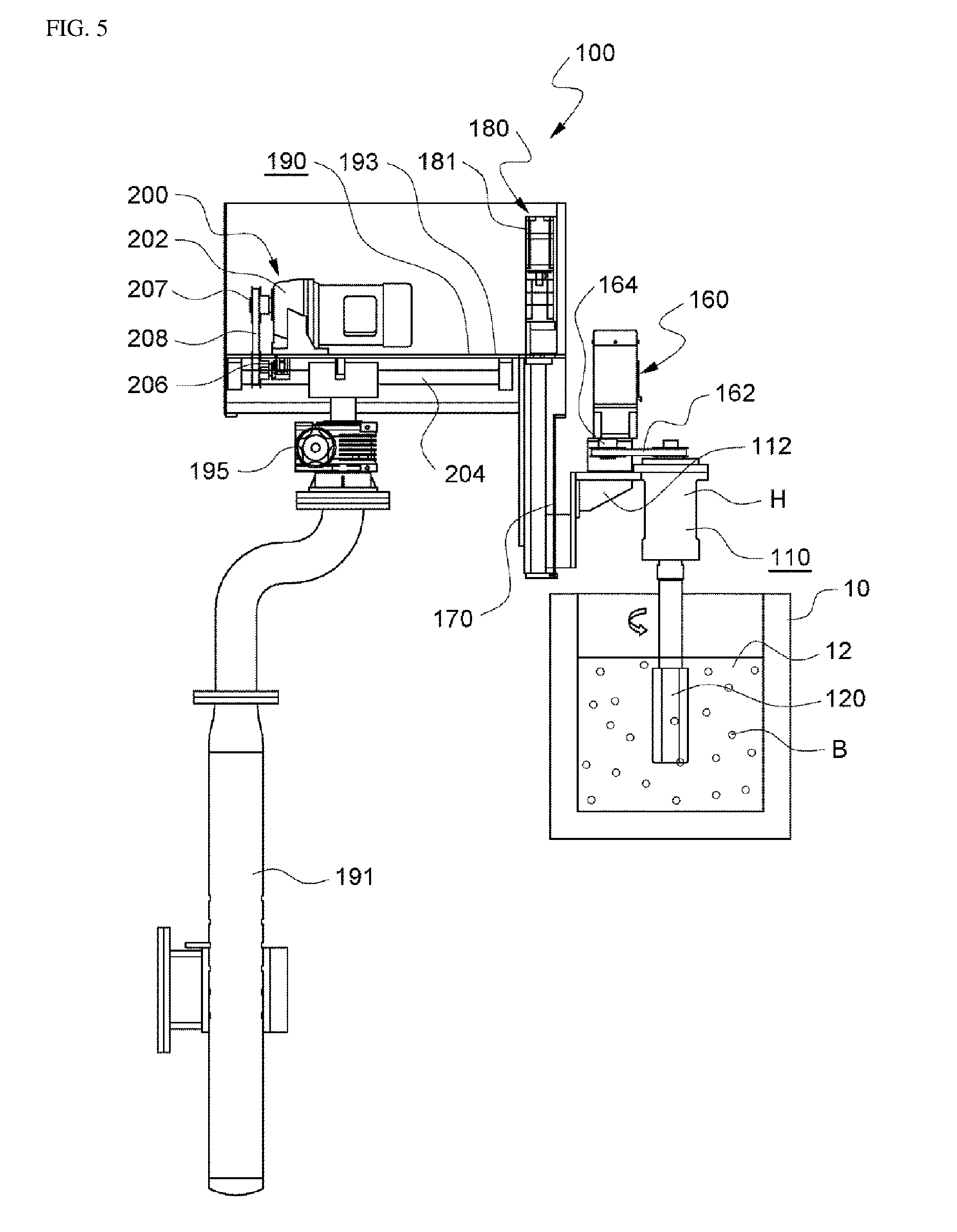
[0046] FIG. 5 is a view for explaining the operation state of the semi-solid slurry generator according to the present invention;
[0047] FIG. 6 is a photograph illustrating a diffuser mounting portion of the semi-solid slurry generator according to the present invention;
[0048] FIG. 7 is an enlarged view illustrating another embodiment of a porous impeller diffuser according to the present invention;
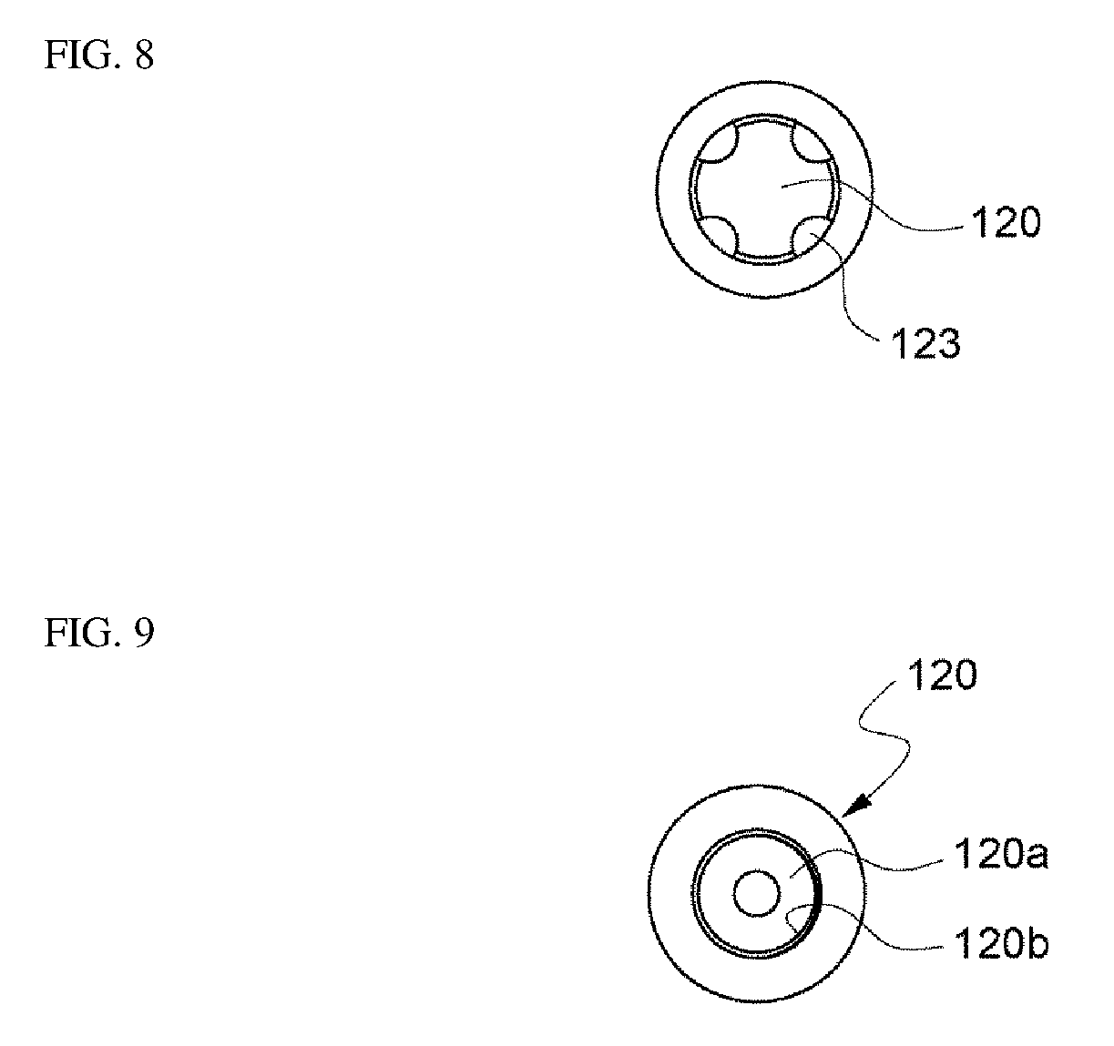
[0049] FIG. 8 is a bottom view of the porous impeller diffuser of FIG. 7;
[0050] FIG. 9 is a plan view of the porous impeller diffuser of FIG. 7;
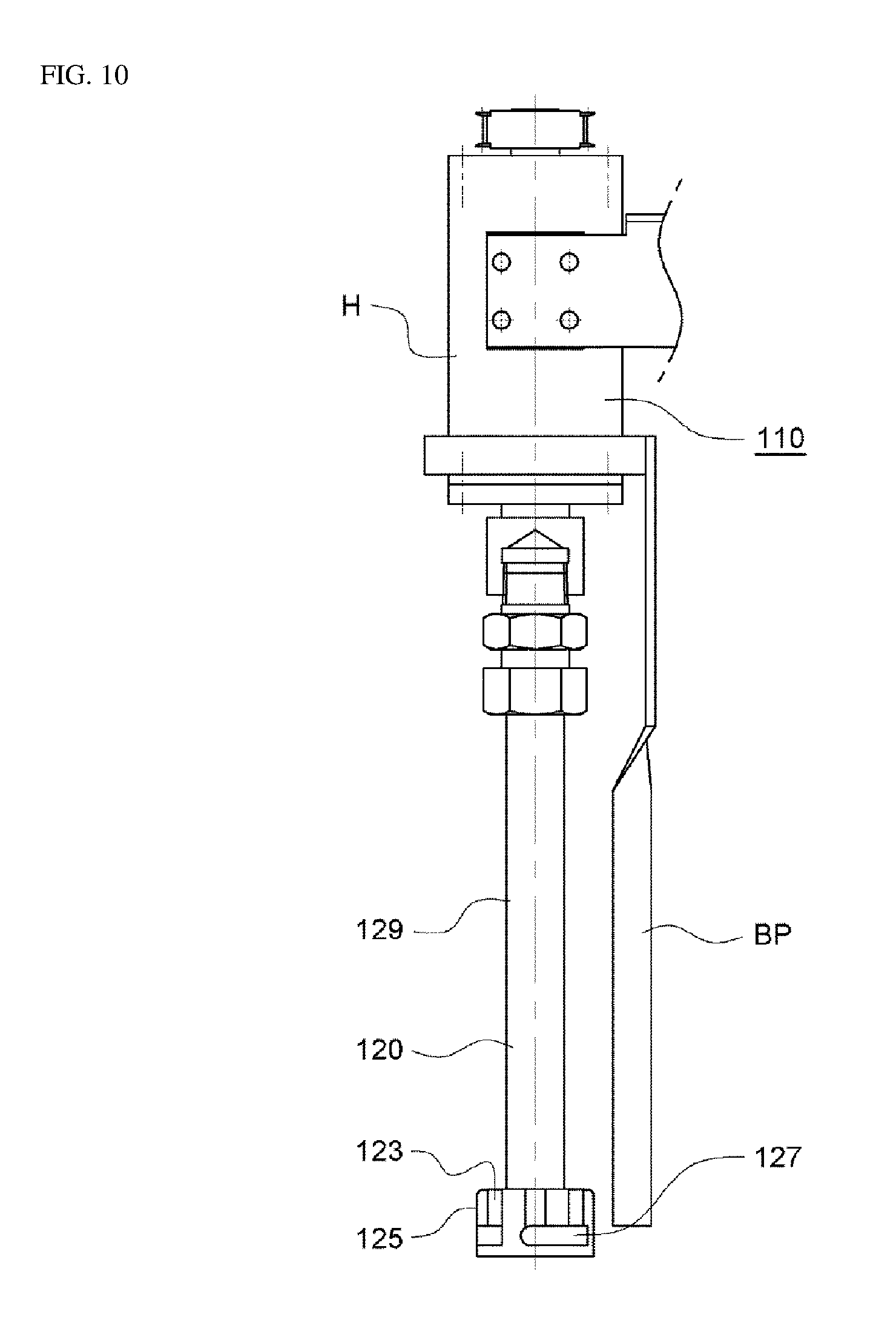
[0051] FIG. 10 is a view illustrating an embodiment of a pumping impeller diffuser according to the present invention;
[0052] FIG. 11 is a bottom view for explaining a preferred internal structure of the pumping impeller;
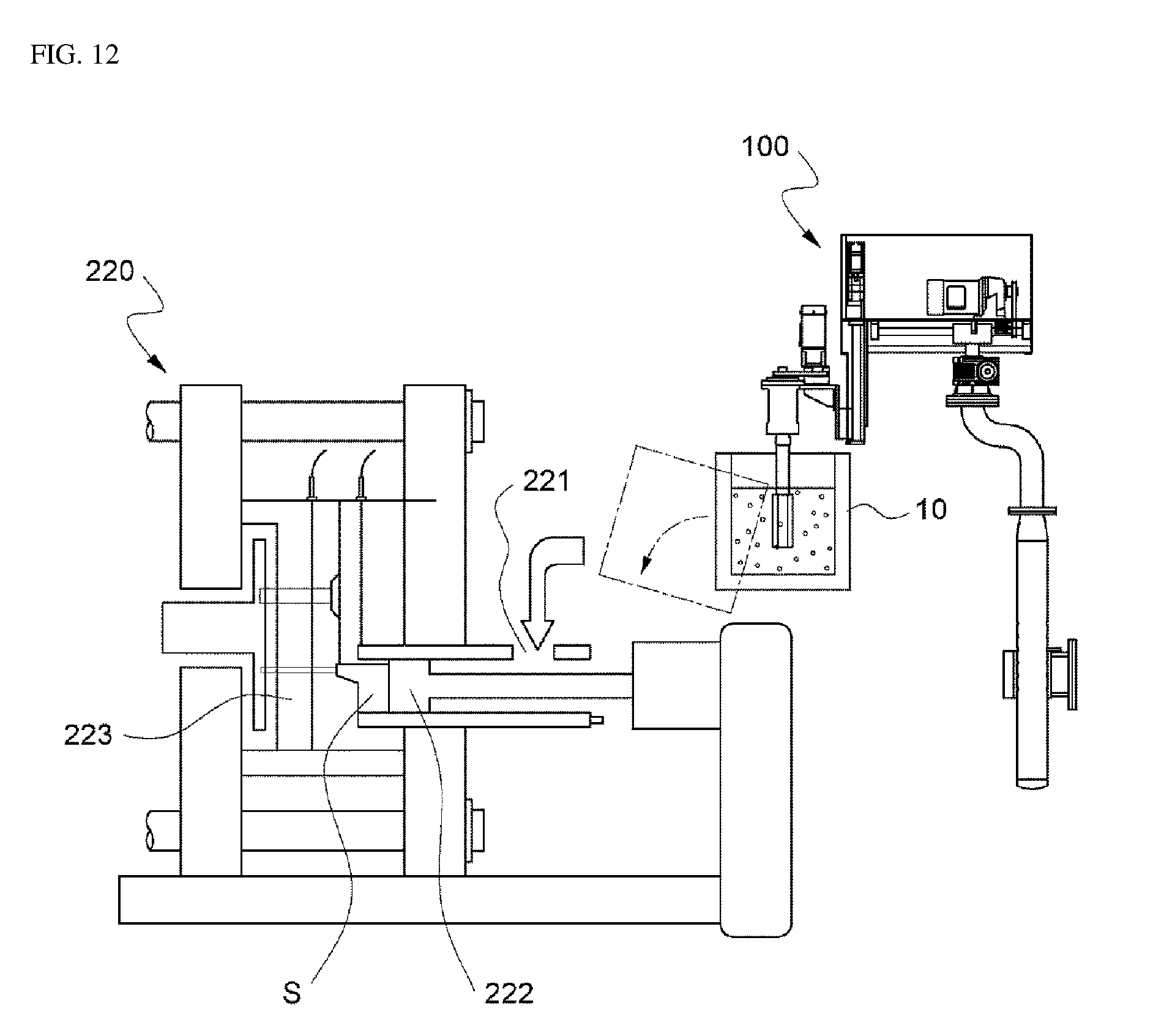
[0053] FIG. 12 is a view for explaining a die casting method according to the present invention; and
[0054] FIG. 13 is a view illustrating another embodiment of a semi-solid slurry generator according to the present invention.
MODE FOR CARRYING OUT THE INVENTION
[0055] Hereinafter, embodiments of the present invention will be described in detail with reference to the accompanying drawings.
[0056] FIG. 3 is a photograph for explaining a semi-solid slurry generator according to the present invention, FIG. 4 is a view for explaining the internal configuration of the semi-solid slurry generator according to the present invention, and FIG. 5 is a view for explaining the operation state of the semi-solid slurry generator according to the present invention.
[0057] Referring to FIGS. 3 to 5, a semi-solid slurry generator 100 according to the present invention is an apparatus for generating a semi-solid slurry by rotating while supplying an inert gas to a molten metal 12 such as an Al-alloy or Mg-alloy contained in a ladle 10, and the semi-solid slurry generator 100 includes a porous diffuser 120 rotatably installed on a pivot support 110. The diffuser 120 preferably includes a porous impeller or a pumping impeller, which will be described in greater detail below. The diffuser 120 includes therein an empty space communicating with the outside, and includes innumerable pores so as to discharge an inert gas, such as argon gas or nitrogen gas, supplied to the empty space to the outer surface.
[0058] The porous diffuser 120 as described above causes the molten metal 12 to flow while cooling the molten metal 12 by stirring the molten metal 12 while supplying the inert gas, such as nitrogen or argon, into the molten metal 12 while rotating and simultaneously moving down into the molten metal 12 contained in the ladle 10 so that the inert gas is bubbled evenly in the entire molten metal 12, thereby breaking the dendritic crystals so as to turn the molten metal 12 into a non-dendritic state. Accordingly, the semi-solid slurry generator 100 according to the present invention increases a quenching effect, that is, a miniaturization of crystals for the entire molten metal compared with the conventional one. Bubbles B formed by the bubbling and evenly distributed throughout the molten metal 12 are capable of collecting and removing harmful gases such as hydrogen evenly throughout the entire molten metal 12.
[0059] Preferably, the diffuser 120 is connected to an inert gas supply unit 130 configured to supply an inert gas through a hose or the like connected to the head H of the semi-solid slurry generator 100 and an air supply unit 135 configured to supply air. The air supply unit 135 is provided for cooling and cleaning the diffuser 120. Preferably, an electronic control valve may be used in order to automatically control air supply and inert gas supply. The air supply unit 135 and the inert gas supply unit 130 are preferably connected to the diffuser 120 through the same single hose. The head H is provided with a rotation support 110 on which the diffuser 120 is rotatably supported.
[0060] As the inert gas supply unit 130, an apparatus such as a pressure container capable of storing a high-pressure gas is used. The head H is preferably provided with a mounting portion such that the diffuser 120 can be easily attached and detached. This will be described in more detail later.
[0061] As illustrated in the drawings, a temperature measuring unit 150 configured to measure the temperature of the molten metal 12 and to apply the measured temperature to the control unit 140 may be installed in the head H including the rotation support 110. Of course, a plurality of temperature sensors or temperature measuring units for temperature measurement may be installed at other positions.
[0062] The semi-solid slurry generator 100 according to the present invention has a rotation unit 160 configured to rotate the diffuser 120 and a slide guide 170 installed in a vertical direction. The rotation unit 160 is installed so as to be vertically movable along the slide guide 170 together with the rotation support 110. A geared motor is suitable as the power source of the rotation unit 160, and the belt 162 and the pulley 164 may be used for power transmission.
[0063] The semi-solid slurry generator 100 according to the present invention is equipped with a lifting unit 180 configured to move up and down the rotation support 110 and the rotation unit 160 along the slide guide 170.
[0064] The lifting unit 180 may be constituted with a servo motor 181 and a ball screw (not illustrated), which is disposed in the vertical direction along the slide guide 170 and is rotated by the servo motor 181. Of course, a lifting member 112, on which the rotation support 110 and the rotation unit 160 are mounted, should be provided with a gear or a thread such that the lifting member 112 can be moved up and down depending on the rotational direction of the ball screw. Of course, other known units other than the ball screw-type unit may be used as the lifting unit.
[0065] The slide guide 170 is supported by a guide support unit 190, and the guide support unit 190 includes a post 191 and a horizontal support 193 connected to the slide guide 170. The horizontal support 193 is installed to be horizontally movable on the post 191, and the horizontal support 193 is provided with a horizontal movement unit 200 configured to move the horizontal support 193 in the horizontal direction.
[0066] The horizontal movement unit 200 includes a geared motor 202, a horizontal shaft 204 provided with a thread or gear teeth, a ball screw 206 engaged with the thread or gear teeth of the horizontal shaft 204 so as to move back and forth depending on the rotation direction of the horizontal shaft 204, and a pulley 207 and a belt 208 that transmit the power of the geared motor 202 to the ball screw 206. The horizontal support 193 is allowed to move to the set position by the operation of the geared motor 202. The movement position of the horizontal support 193 is preferably sensed through a photosensor or the like and applied to a control unit 140 so as to stop the operation of the geared motor 202.
[0067] In addition, the horizontal support 193 is installed to rotate leftwards and rightwards through a vertical shaft 192 at the upper end of the post 191, and the rotation angle of the vertical shaft 192 is adapted to be adjusted by turning an angle adjustment mechanism 195 provided on the post 191 by hand so as to release the locking of the angle adjustment mechanism 195 and locking the angle adjustment mechanism 195 after the angle adjustment. The horizontal movement unit 200 may be any other known horizontal movement units other than the ball screw-type units.
[0068] Referring to FIG. 3, the semi-solid slurry generator 100 according to the present invention preferably includes a control unit 140 configured to control the operation of the rotation unit 160 and the lifting unit 180. The control unit 140 may also control the operation of electromagnetic valves installed in the inert gas supply unit 130 and the air supply unit 135 and the horizontal movement unit 200 as necessary. Of course, these components may be configured to be individually driven through a manual operation of a switch or a valve by an operator. In addition, the semi-solid slurry generator 100 may be provided with the rotation unit 160 and the lifting unit 180 without the horizontal movement unit 200.
[0069] It is preferable that the post 191 extends upwards, then curves laterally, and then extends upwards. In this way, it is possible to operate the semi-solid slurry generator 100 by providing the post 191 at a position sufficiently away from the ladle 10. The post 191 may also be an arch-shaped truss structure or an I-shaped column.
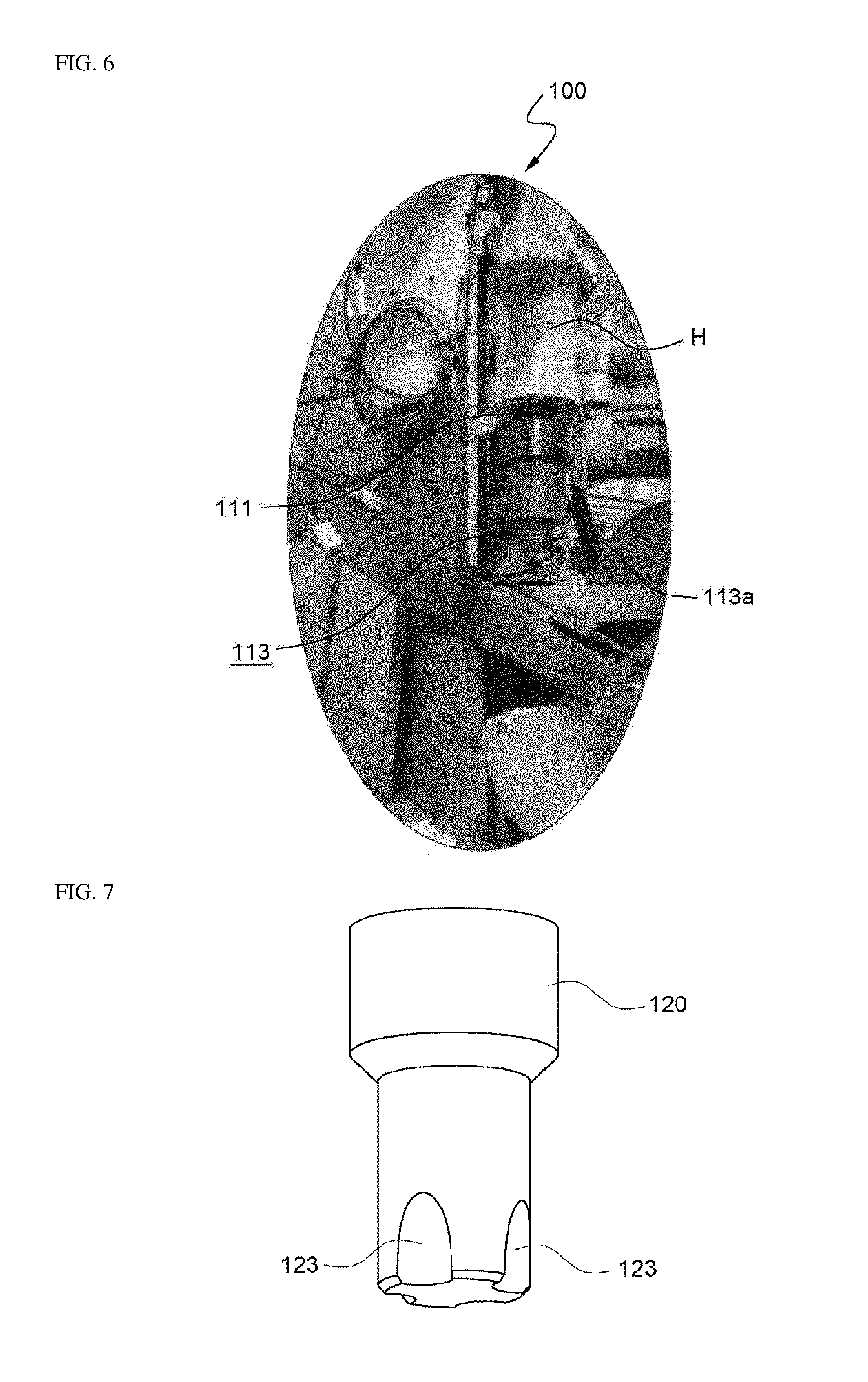
[0070] FIG. 6 is a photograph illustrating a diffuser mounting portion of the semi-solid slurry generator according to the present invention, FIG. 7 is an enlarged perspective view illustrating another embodiment of a porous diffuser according to the present invention, FIG. 8 is a bottom view of the porous diffuser of FIG. 7, and FIG. 9 is a plan view of the porous diffuser of FIG. 7.
[0071] As illustrated in FIG. 6, the head H is provided with a rotary shaft 111, and the rotary shaft 111 is provided with a diffuser mounting portion 113. As the diffuser mounting portion 113, a screw coupling-type mounting portion is preferably used. For this purpose, threads 113a and 120b may be formed on the outer circumferential surface of the mounting portion 113 and the inner circumferential surface of the empty space 120a in the diffuser 120 configured to supply an inert gas, so that the diffuser 120 can be screw-coupled to the mounting portion 113.
[0072] In addition, the porous diffuser 120 may be configured to have an impeller function by providing grooves 123 or protrusions, which are spaced apart from each other along the outer circumferential surface of the diffuser 120 so as to allow the molten metal to flow well when the diffuser 120 rotates to have an impeller function. The grooves or protrusions serve as wings for stirring the molten metal 12. In order to increase the effect of stirring the molten metal 12 when the diffuser 120 rotates, the grooves 123 or protrusions may be formed on the outer circumferential surface of the diffuser 120, or the outer circumferential surface of the diffuser 120 may be formed in a polygonal shape, and the portion serving as an impeller is preferably provided at the lower end of the diffuser 120. In addition, in order to make the diffuser 120 have the impeller function, the cross section of the diffuser 120 may have a polygonal shape such as an octagon, a heptagon, a hexagon, a pentagon, or a tetragon. Further, the diffuser 120 may have a polygonal cross section as a whole or in part, or a cross section in which grooves, curved surfaces, or irregularities are formed. The diffuser 120 illustrated in FIGS. 4 and 5 has an octagonal cross-sectional shape.
[0073] In some cases, at least one separate impeller may be provided so as to stir the molten metal.
[0074] The diffuser 120 according to the present invention is preferably made of ceramics or graphite. Particularly, ceramics have a characteristic in that a molten metal hardly adheres thereto, and have a long lifetime. Micropores, which allow the inert gas supplied to the inner empty space 120a to be exposed to the outside, are formed before baking the porous diffuser 120, after the external appearance of which has been formed.
[0075] The operation of the semi-solid slurry generator 100 according to the present invention will now be described with reference to FIGS. 3 to 6.
[0076] The control unit 140 of the semi-solid slurry generator 100 according to the present invention operates the horizontal movement unit 200 so as to horizontally move the diffuser 120 to the upper side of the ladle 10 stopped at a predetermined position, and stop the diffuser 120 at normal position not to collide with the ladle. When the ladle 10 containing the molten metal arrives at the set position or under the diffuser 120 for the casting operation, the lifting unit 180 is operated to lower the diffuser 120 and the diffuser 120 is rotated as indicated by an arrow by the rotation unit 160, and the diffuser 120 is immersed into the molten metal 12 while supplying the inert gas of the inert gas supply unit 130 by opening the valve of the inert gas supply unit 130. At this time, the diffuser 120 is lowered to a position which is set such that the diffuser 120 does not hit the inner bottom surface of the ladle.
[0077] As the porous diffuser 120 rotates, a swirling flow occurs in the molten metal 12, and the inert gas supplied into the molten metal 12 evenly bubbles the entire molten metal 12. Particularly, in the porous diffuser 120 according to the present invention, the grooves 123, protrusions, or a polygon formed so as to function as an impeller become blades, a porous impeller, or a pump impeller, so that the molten metal 12 is harmoniously stirred and the inert gas is evenly penetrated into the molten metal 12.
[0078] As the geared motor constituting the rotating means 160, a geared motor, which is bi-directionally drivable, is used so as to change the rotating direction of the diffuser 120, so that the inert gas can be evenly dispersed and stirred in the entire molten metal 12. Further, in order to increase the bubbling effect by rotation driving, a baffle plate may be further disposed around the diffuser 120, which will be described in more detail later.
[0079] The inert gas is supplied into the molten metal 12 for a predetermined time or until the temperature of the molten metal 12 drops to a predetermined temperature while rotating the diffuser 120 in the above-described manner. Preferably, when the temperature of the molten metal 12, which is inputted by the temperature measuring unit 150, falls to a target temperature, the valve of the inert gas supply unit 130 is locked to stop the supply of the inert gas, the operation of the rotation unit 160 is stopped, the lifting unit 180 is operated to raise the diffuser 120, and then air is supplied from the air supply unit 135 to the inside of the diffuser 120 so as to wait until the next process while cooling the diffuser 120 for performing the next process and maintaining cleanliness.
[0080] In this manner, the inert gas is evenly penetrated into the entire molten metal 12, and a slurry having a good quenching effect over the entire molten metal can be obtained.
MODE FOR CARRYING OUT THE INVENTION
[0081] FIG. 10 is a view illustrating an embodiment of a pumping impeller diffuser according to the present invention, and FIG. 11 is a bottom view for explaining a preferred internal structure of the pumping impeller.
[0082] The diffuser 120 illustrated in FIG. 10 may have a pumping impeller 125 at the lower end thereof. The pumping impeller 125 includes a hollow portion 126 that has an opened lower portion and communicates with the inert gas supply unit 130 described in the preceding embodiment with reference to FIG. 3 and lateral holes 127 that are formed in the side surface and communicate with the internal hollow portion 126. The lateral holes 127 are provided to be deviated laterally from the center rather than being oriented toward the center of the hollow portion 126 so as to allow the inner molten metal to be discharged by a centrifugal force. The inner ends of the lateral holes 127 are inclined with respect to the center line perpendicular to the forming direction of the lateral holes 127. Accordingly, the molten metal rotating within the hollow portion 126 is capable of being strongly ejected outward through the lateral holes 127 by colliding against portions protruding more towards the vertical center line by the centrifugal force and changing the direction, which greatly improves the stirring effect.
[0083] The pumping impeller 125 has a pumping function of rotationally stirring the molten metal while ejecting the molten metal by a centrifugal force by being rotated and stirring the inert gas supplied from the inert gas supply unit 130 and the molten metal sucked into the hollow portion 126 from the lower portion of the opened hollow portion 126. When the molten metal within the hollow portion 126 is ejected to the outside through the lateral holes 127, the molten metal is naturally sucked into the hollow portion 126 through the opened lower portion of the hollow portion 126.
[0084] It is preferable that the pumping impeller 125 as described above is detachably coupled to a portion of a bar 129 constituting the diffuser 120 above the pumping impeller 125 through a screw connection. The pumping impeller 125 is supplied with the inert gas into the hollow portion 126 through an inert gas supply hole 129a formed in the bar 129.
[0085] In the outer circumferential surface of the pumping impeller 125, grooves 123 are provided in order to improve the rotation effect of the molten metal. Protrusions or the like may be provided instead of the grooves.
[0086] The diffuser 120 is rotatably mounted on the rotation support 110 of the head H, and the head H is preferably provided with a baffle BP, which generates turbulence by interfering with the rotation of the molten metal which is rotated by the diffuser 120, thereby causing the molten metal to be effectively stirred with the inert gas.
[0087] When the diffuser 120 as described above with reference to FIGS. 10 and 11 rotates, the molten metal is sucked into the hollow portion 126 provided in the central portion of the pumping impeller 125, the sucked molten metal is stirred with the inert gas supplied through the inert gas supply hole 129a communicating with the inert gas supply unit 130, and the molten metal is ejected by a centrifugal force through the holes 127 provided in the side surface of the pumping impeller 125 by the centrifugal force. The molten metal and the inert gas, which are ejected in this way, are simultaneously rotated and stirred in the ladle to obtain a more even semi-solid slurry.
[0088] The diffuser 120 provided with the pumping impeller 125 as described above is lowered into the molten metal 12 contained in the ladle 10, and simultaneously the molten metal flows into the hollow portion 126 of the pumping impeller 125. As the pumping impeller 125 is rotated, an inert gas such as nitrogen or argon is supplied and mixed into the molten metal 12 within the hollow portion 126, as the molten metal mixed with the inert gas is ejected through the lateral holes 127 by the centrifugal force and rotational stirring is also performed even outside the pumping impeller 125, the molten metal 12 is cooled and fluidized and the inert gas is caused to bubble more evenly throughout the entire molten metal 12, thereby breaking the dendritic crystals so as to turn the molten metal 12 into a non-dendritic state.
[0089] When the molten metal within the hollow portion 126 is drawn out through the lateral holes 127 by the centrifugal force, the molten metal is naturally sucked into the hollow portion 126 through the opened lower portion of the hollow portion 126, and the above-described processes are repeated, which causes the inert gas to be uniformly distributed throughout the entire molten metal.
[0090] Accordingly, the semi-solid slurry generator 100 according to the present invention further increases a quenching effect, that is, the miniaturization for crystals of the entire molten metal compared with the conventional one. Bubbles B formed by the bubbling and evenly distributed throughout the molten metal 12 are capable of collecting and removing harmful gases such as hydrogen evenly throughout the entire molten metal 12.
[0091] FIG. 12 is a view for explaining a die casting method according to the present invention. In the following description, FIGS. 3 to 11 are also referred to.
[0092] In the semi-solid slurry generator 100 described above with reference to FIGS. 3 to 11, the diffuser 120 preferably including the impeller is moved forwards to the upper side of the ladle 10 through the horizontal movement unit 200, the diffuser 120 is lowered to be immersed in the molten metal 12 through the lifting unit 180, and the inert gas is supplied into the molten metal 12 while rotating the diffuser 120 by the rotation unit 160. At this time, when the diffuser 120 having the impeller function or the diffuser 120 having the pumping impeller 125 is used, more effective stirring can be performed by the impeller function and by rotating and pumping the molten metal.
[0093] As the diffuser 120 rotates, flowing and swirling occur in the molten metal 12, and the inert gas supplied into the molten metal 12 is evenly bubbled and stirred throughout the entire molten metal 12. When the rotation direction of the diffuser 120 is changed using a motor, which is bi-directionally drivable, as the rotation unit 160, the inert gas is dispersed more evenly throughout the entire molten metal 12, so that the entire molten metal can be evenly stirred and a slurry having a good quenching effect can be obtained. Further, the baffle plate may be disposed around the diffuser 120 in order to increase the bubbling effect by rotational driving.
[0094] When the temperature of the molten metal 12 drops to a target temperature, the supply of the inert gas is stopped, the operation of the rotation unit 160 is stopped, the lifting unit 180 is operated to raise the diffuser 120, and then air is supplied to the inside of the diffuser 120 so as to maintain the cleanliness while cooling the diffuser 120.
[0095] When the semi-solid slurry B, which is generated as described above and contained in the ladle 10, is poured into a plunger 221 of a die casting machine 220 and is introduced into a mold 223 with high pressure using a piston 222 so as to be molded, it is possible to obtain a dense product. At this time, it is preferable that the semi-solid slurry B is supplied to the plunger 221 of the die casting machine 220 at a temperature that is equal to or lower than the melting point of the metal.
[0096] FIG. 13 is a view illustrating another example of a semi-solid slurry generator according to the present invention.
[0097] In some cases, when a baffle plate BP is disposed to be laterally spaced apart from the diffuser 120 in the head H constituting the rotation support 110, stirring and bubbling may be performed well throughout the entire molten metal by controlling the rotational movement of the molten metal rotating in the ladle by the rotation of the diffuser 120. A plurality of baffle plates BP may be installed. The remaining features are the same as those described with reference to FIGS. 3 to 5.
[0098] The present inventor fabricated specimens through high-pressure die casting of a semi-solid slurry according to the method of the present invention as described above, and obtained physical property data thereof. The tensile strength of the specimens obtained through the high-pressure die casting of a semi-solid slurry is described below. The specimens were manufactured by specimen molds designed according to ASTM B 557 standards. The alloys used for the specimens were ADC10 (A380, AlSi.sub.8Cu.sub.3Fe) and EN43500 (AlSi.sub.10MnMg). The melting point of ADC10 was 598.degree. C., the temperature in the die casting process was 572.degree. C., and the temperature of the molten metal after degassing was 680.degree. C. The melting point of EN43500 was 593.degree. C., and the temperature of the molten metal after degassing was 689.degree. C. The following process was performed on a molten metal contained in the ladle in order to obtain a semi-solid slurry. The material of the porous impeller diffuser used for manufacturing the ADC 10 alloy specimens was a porous ceramic having a density of 2.7 g/cm.sup.3, a porosity of 20%, and a bending strength of 17 MPa. The material of the pumping impeller diffuser used for manufacturing EN43500 specimens was graphite having a crystal size of 52 to 15 .mu.m and a hardness of 70.
[0099] Molten metal quenching of the ADC 10 alloy by gas bubbling of an inert gas (N.sub.2) and rotation was started at temperatures of 625.degree. C. and 640.degree. C., and respective quenching times were 10 seconds, 15 seconds, 20 seconds, 25 seconds, and 30 seconds. The temperature of the molten metal for the conventional high-pressure die casting was 660.degree. C. The temperature before supplying the molten metal to the plunger after quenching was 585.degree. C. to 594.degree. C., which is equal to or lower than the melting point. Molten metal quenching of the EN43500 alloy by gas bubbling of an inert gas (N2) and rotation was started at a temperature of 660.degree. C., each quenching time was 30 seconds, and the temperature before supplying the molten metal to the plunger after quenching was 592.degree. C., which is equal to or lower than melting point.
[0100] In Table 1, the temperature before supplying a material to the plunger of high-pressure die casting is equal to or lower than the melting point of the material.
[0101] That is, Table 1 shows that when the temperature of the molten metal after quenching by the bubbling of the inert gas (N.sub.2) and rotation reach between the melting point of the alloy and the temperature in the die casting process of the alloy, semi-solid slurry effects were exhibited.
[0102] As can be seen from Table 1, compared to the strength (yield/tensile strength=166/279 MPa) of the conventional high-pressure die casting products, the yield strength (192 MPa) and the tensile strength (292 MPa) of the semi-solid slurry-treated AlSi.sub.8Cu.sub.3Fe (ADC10) were improved by 15% or more in yield strength and by 4% or more in tensile strength, respectively, and the elongation of the semi-solid slurry-treated AlSi.sub.8Cu.sub.3Fe (ADC10) was reduced from 3.4% to 2.4% compared with the conventional high-pressure die casting products. In addition, the strength of the EN43500 alloy manufactured using a pumping impeller diffuser was compared before and after the heat treatment T6. No pores were found on the surfaces of the specimens after heat treatment. The heat treatment T6 was performed at 500.degree. C. for 1 hour and then performed at 160.degree. C. for 8 hours. That is, using a pumping impeller shows that a heat treatment can be performed to achieve high strength.
[0103] The temperature of the molten metal in Table 1 was measured using a K-type thermocouple.
TABLE-US-00001 TABLE 1 Result of Tensile Test of Semi-solid Slurry Specimen Temp. of Temp. Molten of Metal Molten Gas Tensile Yield Before Metal Bubbling Strength Strength Elongation Introduced Alloy (.degree. C.) Time (sec) (MPa) (MPa) (%) into Plunger Note ADC10 625 10 299 195 3.1 590 Porous 15 297 192 3.3 590 Impeller 30 299 196 2.8 585 Diffuser 640 20 299 205 2.4 594 25 292 200 2.5 588 30 300 193 2.8 588 660 -- 279 166 3.4 -- High-pressure Die Casting EN43500 690 35 274 154 4.9 592 Before Pumping Heat Impeller Treatment Diffuser 311 231 7.7 T6 Heat Treatment
INDUSTRIAL APPLICABILITY
[0104] The present invention may be used to make automotive components that require high strength and high elongation using a lightweight metal such as an Al-alloy or an Mg-alloy. Further, the present invention may be used to make other die casting products in addition to the automobile components.
* * * * *
D00000
D00001
D00002
D00003
D00004
D00005
D00006
D00007
D00008
D00009
D00010
D00011
XML
uspto.report is an independent third-party trademark research tool that is not affiliated, endorsed, or sponsored by the United States Patent and Trademark Office (USPTO) or any other governmental organization. The information provided by uspto.report is based on publicly available data at the time of writing and is intended for informational purposes only.
While we strive to provide accurate and up-to-date information, we do not guarantee the accuracy, completeness, reliability, or suitability of the information displayed on this site. The use of this site is at your own risk. Any reliance you place on such information is therefore strictly at your own risk.
All official trademark data, including owner information, should be verified by visiting the official USPTO website at www.uspto.gov. This site is not intended to replace professional legal advice and should not be used as a substitute for consulting with a legal professional who is knowledgeable about trademark law.