Electrical stimulation control circuit and control method thereof
HSU; Chia-Chan ; et al.
U.S. patent application number 15/857361 was filed with the patent office on 2019-06-20 for electrical stimulation control circuit and control method thereof. The applicant listed for this patent is Industrial Technology Research Institute, KAOHSIUNG MEDICAL UNIVERSITY. Invention is credited to Chia-Chan HSU, Chao-Jen HUANG, Su-Shin LEE.
| Application Number | 20190184157 15/857361 |
| Document ID | / |
| Family ID | 63257345 |
| Filed Date | 2019-06-20 |


| United States Patent Application | 20190184157 |
| Kind Code | A1 |
| HSU; Chia-Chan ; et al. | June 20, 2019 |
Electrical stimulation control circuit and control method thereof
Abstract
An electrical stimulation control circuit including a pulse generator, a processing circuit and an electrode is provided. The pulse generator is configured to generate a switching signal. The processing circuit generates an energy signal according to the switching signal. The electrode is configured to contact the skin of a living body and includes a first comb electrode and a second comb electrode. The first comb electrode receives the energy signal and includes a plurality of first electrodes. The first electrodes are electrically connected to each other and extended along a first direction. The second comb electrode receives a ground signal and includes a plurality of second electrodes. The second electrodes are electrically connected to each other and extended along a second direction opposite to the first direction. The first electrodes and the second electrodes are arranged in a staggered manner and electrically insulated from each other.
| Inventors: | HSU; Chia-Chan; (Tainan City, TW) ; HUANG; Chao-Jen; (Hsinchu County, TW) ; LEE; Su-Shin; (Kaohsiung City, TW) | ||||||||||
| Applicant: |
|
||||||||||
|---|---|---|---|---|---|---|---|---|---|---|---|
| Family ID: | 63257345 | ||||||||||
| Appl. No.: | 15/857361 | ||||||||||
| Filed: | December 28, 2017 |
Related U.S. Patent Documents
| Application Number | Filing Date | Patent Number | ||
|---|---|---|---|---|
| 62598597 | Dec 14, 2017 | |||
| Current U.S. Class: | 1/1 |
| Current CPC Class: | A61N 1/326 20130101; A61N 1/323 20130101; A61N 1/0468 20130101; A61N 1/36017 20130101; A61N 1/3603 20170801; A61N 1/328 20130101; A61N 1/36034 20170801; A61N 1/0476 20130101 |
| International Class: | A61N 1/32 20060101 A61N001/32; A61N 1/36 20060101 A61N001/36; A61N 1/04 20060101 A61N001/04 |
Claims
1. An electrical stimulation control circuit comprising: a pulse generator configured to generate a switching signal; a processing circuit generating an energy signal according to the switching signal; and an electrode configured to contact the skin of a living body and comprising: a first comb electrode receiving the energy signal and comprising a plurality of first electrodes, wherein the first electrodes are electrically connected to each other and extend in a first direction; and a second comb electrode receiving a ground voltage and comprising a plurality of second electrodes, wherein the second electrodes are electrically connected to each other and extend in a second direction opposite to the first direction, wherein the first electrodes and the second electrodes are arranged in a staggered manner and are electrically insulated from each other.
2. The electrical stimulation control circuit as claimed in claim 1, wherein during a first period, the energy signal is equal to a first voltage, during a second period, the energy signal is equal to a second voltage, the first voltage is higher than the second voltage, the duration of the first period is 15 minutes, and the duration of the second period is between 2.5 hours and 24 hours.
3. The electrical stimulation control circuit as claimed in claim 2, wherein when the electrode is attached to the skin of a living body and the energy signal is equal to the first voltage, a current passes through the first comb electrode, the skin of the living body and the second comb electrode, and the current is between 50 .mu.A and 600 .mu.A.
4. The electrical stimulation control circuit as claimed in claim 1, wherein the processing circuit comprises: an energy storage element; and a power circuit acquiring energy from the energy storage element to generate the energy signal.
5. The electrical stimulation control circuit as claimed in claim 4, wherein the energy storage element is a lithium ion capacitor, a supercapacitor or a battery.
6. The electrical stimulation control circuit as claimed in claim 4, wherein the power circuit charges the energy storage element according to the switching signal.
7. The electrical stimulation control circuit as claimed in claim 4, wherein the power circuit comprises a single-inductor multiple-input-multiple-output circuit.
8. The electrical stimulation control circuit as claimed in claim 4, further comprising: a thermoelectric generator configured to contact the living body and to generate a charge signal according to the body temperature of the living body, wherein the power circuit charges the energy storage element according to the charge signal.
9. The electrical stimulation control circuit as claimed in claim 8, wherein the power circuit comprises: a first converter charging the energy storage element according to the charge signal; and a second converter acquiring the energy from the energy storage element according to the switching signal to generate the energy signal.
10. The electrical stimulation control circuit as claimed in claim 8, wherein the power circuit comprises: a first converter charging the energy storage element according to the charge signal; a second converter acquiring the energy from the energy storage element to generate the energy signal; and a switch coupled between the second converter and the electrode and transmitting the energy signal to the electrode according to the switching signal.
11. A control method for stimulating skin cells of a living body, comprising: generating a switching signal; generating an energy signal according to the switching signal; and transmitting the energy signal to the skin of the living body via an electrode, wherein the electrode comprises: a first comb electrode receiving the energy signal and comprising a plurality of first electrodes, wherein the first electrodes are electrically connected to each other and extend in a first direction; and a second comb electrode receiving a ground voltage and comprising a plurality of second electrodes, wherein the second electrodes are electrically connected to each other and extend in a second direction opposite to the first direction, wherein the first electrodes and the second electrodes are arranged in a staggered manner and are electrically insulated from each other.
12. The control method as claimed in claim 11, wherein during a first period, the energy signal is equal to a first voltage, during a second period, the energy signal is equal to a second voltage, the first voltage is higher than the second voltage, the duration of the first period is 15 minutes, and the duration of the second period is between 2.5 hours and 24 hours.
13. The control method as claimed in claim 11, wherein when the electrode is attached to the skin of the living body and the energy signal is equal to the first voltage, a current passes through the first comb electrode, the skin of the living body and the second comb electrode, and the current is between 50 .mu.A and 600 .mu.A.
14. The control method as claimed in claim 11, wherein the step of generating the energy signal according to the switching signal comprises: acquiring energy stored in an energy storage element according to the switching signal; and converting the energy stored in the energy storage element to generate the energy signal.
15. The control method as claimed in claim 14, further comprising: charging the energy storage element according to the switching signal.
16. The control method as claimed in claim 14, further comprising: generating a charge signal according to a body temperature of the living body to charge the energy storage element.
Description
FIELD OF THE INVENTION
[0001] The present disclosure relates to a control circuit, and more particularly to a control circuit that applies electrical stimulation to activate skin regeneration.
BACKGROUND
[0002] When a human body experiences physical trauma, a wound often remains on the surface of the skin. Some conventional methods of treating a wound are to bind a bandage over the wound, put a dressing on the wound, or attach artificial skin to the wound. However, these conventional treatment methods are time-consuming and expensive.
SUMMARY
[0003] In accordance with an embodiment, an electrical stimulation control circuit comprises a pulse generator, a processing circuit and an electrode. The pulse generator is configured to generate a switching signal. The processing circuit generates an energy signal according to the switching signal. The electrode is configured to contact the skin of a living body and comprises a first comb electrode and a second comb electrode. The first comb electrode receives the energy signal and comprises a plurality of first electrodes. The first electrodes are electrically connected to each other and extend in a first direction. The second comb electrode receives a ground voltage and comprises a plurality of second electrodes. The second electrodes are electrically connected to each other and extend in a second direction opposite to the first direction. The first electrodes and the second electrodes are arranged in a staggered manner and are electrically insulated from each other.
[0004] In accordance with a further embodiment, a control method for stimulating skin cells of a living body comprises generating a switching signal; generating an energy signal according to the switching signal; and transmitting the energy signal to the skin of the living body via an electrode. The electrode comprises a first comb electrode and a second comb electrode. The first comb electrode receives the energy signal and comprises a plurality of first electrodes. The first electrodes are electrically connected to each other and extend in a first direction. The second comb electrode receives a ground voltage and comprising a plurality of second electrodes. The second electrodes are electrically connected to each other and extend in a second direction opposite to the first direction. The first electrodes and the second electrodes are arranged in a staggered manner and are electrically insulated from each other.
BRIEF DESCRIPTION OF THE DRAWINGS
[0005] The present disclosure can be more fully understood by referring to the following detailed description and examples with references made to the accompanying drawings, wherein:
[0006] FIG. 1A is a schematic diagram of an exemplary embodiment of an electrical stimulation control circuit according to various aspects of the present disclosure.
[0007] FIG. 1B is a schematic diagram of another exemplary embodiment of the electrical stimulation control circuit according to various aspects of the present disclosure.
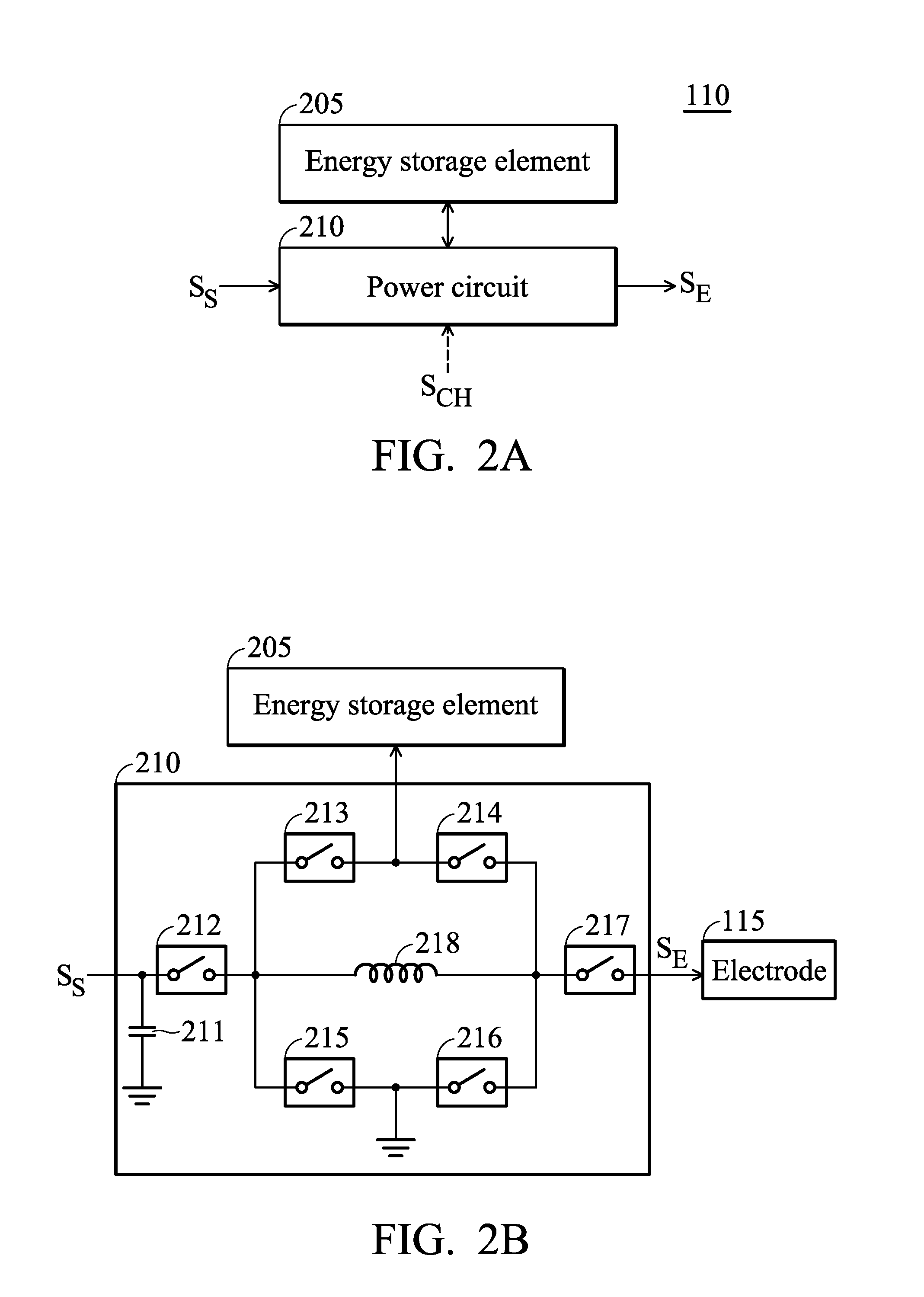
[0008] FIG. 2A is a schematic diagram of an exemplary embodiment of a processing circuit according to various aspects of the present disclosure.
[0009] FIG. 2B is a schematic diagram of an exemplary embodiment of a power circuit according to various aspects of the present disclosure.
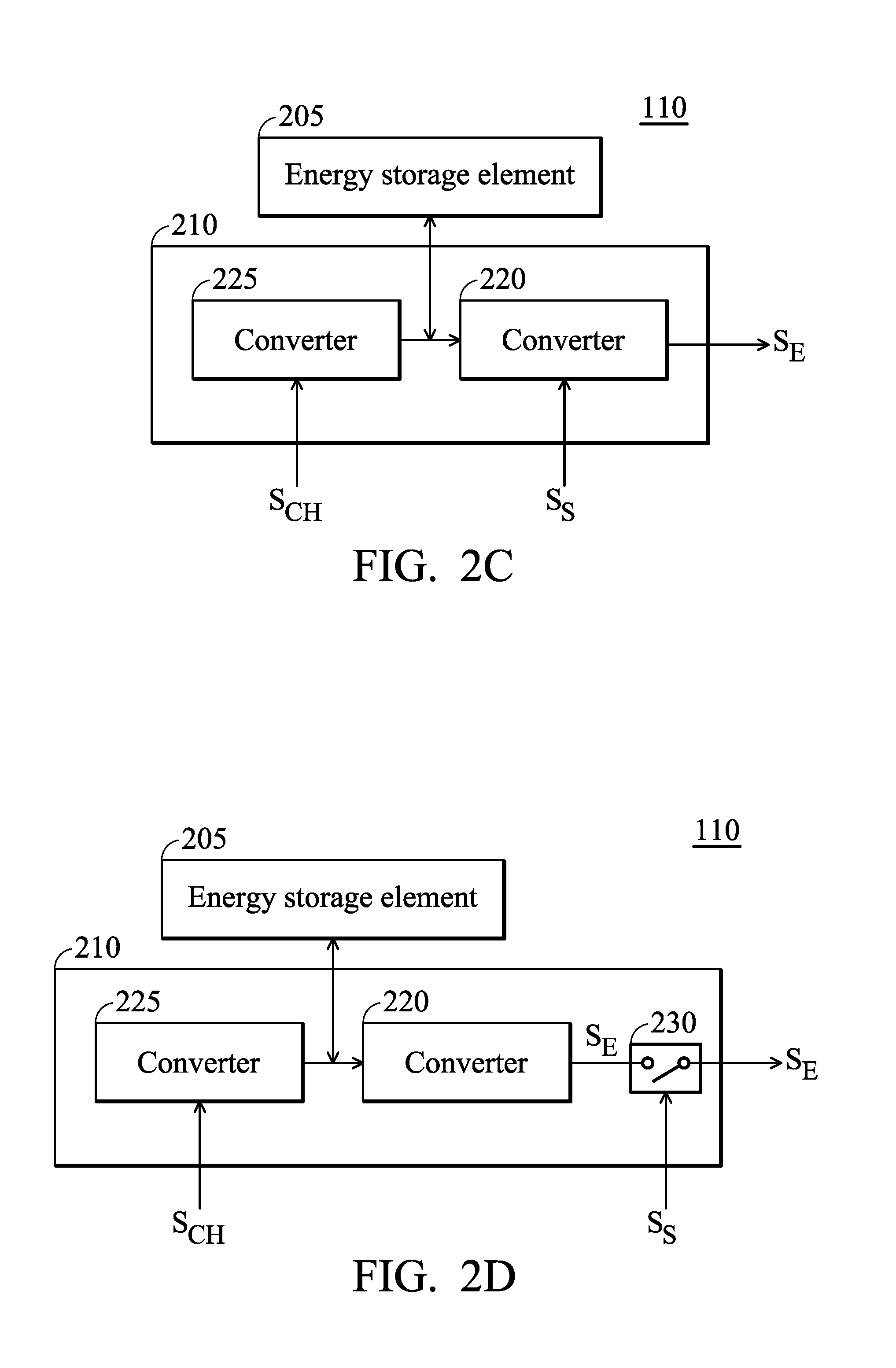
[0010] FIG. 2C is a schematic diagram of another exemplary embodiment of the processing circuit according to various aspects of the present disclosure.
[0011] FIG. 2D is a schematic diagram of another exemplary embodiment of the processing circuit according to various aspects of the present disclosure.
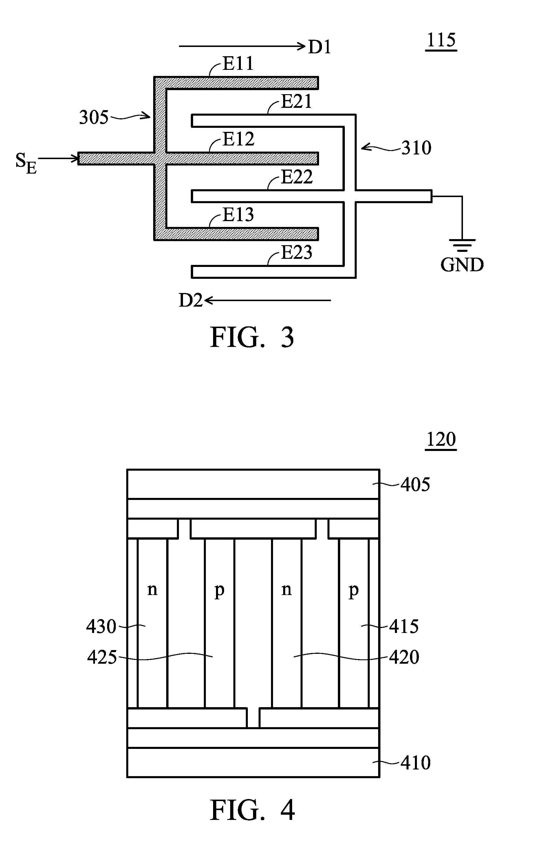
[0012] FIG. 3 is a schematic diagram of an exemplary embodiment of an electrode according to various aspects of the present disclosure.
[0013] FIG. 4 is a schematic diagram of an exemplary embodiment of a thermoelectric generator according to various aspects of the present disclosure.
[0014] FIGS. 5A-5C are schematic diagrams of exemplary embodiments of energy signal according to various aspects of the present disclosure.
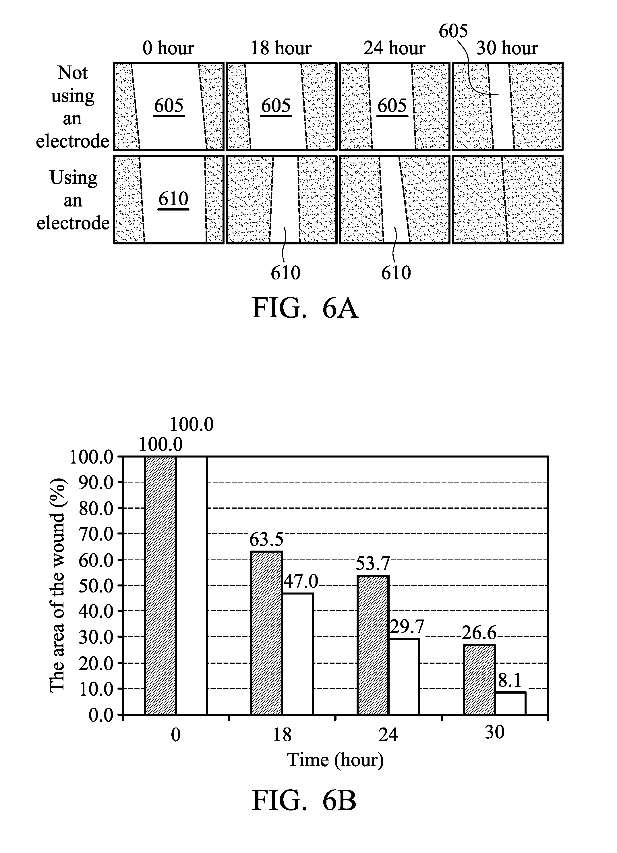
[0015] FIG. 6A is a schematic diagram of a wound restoration of using and not using an electrode.
[0016] FIG. 6B is an area ratio diagram of a wound.
[0017] FIG. 7 is a flowchart schematic diagram of an exemplary embodiment of a control method according to various aspects of the present disclosure.
DETAILED DESCRIPTION OF THE INVENTION
[0018] The present disclosure will be described with respect to particular embodiments and with reference to certain drawings, but the present disclosure is not limited thereto and is only limited by the claims. The drawings described are only schematic and are non-limiting. In the drawings, the size of some of the elements may be exaggerated for illustrative purposes and not drawn to scale. The dimensions and the relative dimensions do not correspond to actual dimensions in the practice of the present disclosure.
[0019] FIG. 1A is a schematic diagram of an exemplary embodiment of an electrical stimulation control circuit according to various aspects of the present disclosure. As shown in FIG. 1A, the electrical stimulation control circuit 100A comprises a pulse generator 105, a processing circuit 110 and an electrode 115. The pulse generator 105 is configured to generate a switching signal S.sub.S. In one embodiment, the pulse generator 105 adjusts the frequency of the switching signal S.sub.S and the duty-cycle of the switching signal S.sub.S according to a set signal (not shown).
[0020] In the disclosure, the internal circuit structure of the pulse generator 105 is not limited. In one embodiment, the pulse generator 105 comprises an analog circuit (not shown) and a comparing circuit (not shown). The analog circuit is configured to generate a triangle wave or a sawtooth wave. The comparing circuit compares the triangle wave or the sawtooth wave with a reference signal to generate a square wave. In this case, the square wave serves as the switching signal S.sub.S.
[0021] The processing circuit 110 generates an energy signal S.sub.E according to the switching signal S.sub.S. In one embodiment, when the switching signal S.sub.S is at a first level, the processing circuit 110 sets the energy signal S.sub.E to equal to a first voltage. When the switching signal S.sub.S is at a second level, the energy signal S.sub.E is set to equal to a second voltage. In this embodiment, the first voltage is higher than the second voltage. In one embodiment, the second voltage is a ground voltage, such as 0V. In addition, the first level is opposite to the second level. When the first level is at a high level, the second level is at a low level. When the first level is at the low level, the second voltage is at the high level.
[0022] The electrode 115 is configured to contact the skin of a living body. The type of electrode 115 is not limited in the disclosure. In one embodiment, the electrode 115 is a thermoelectric dressing electrode. In this embodiment, when the electrode 115 receives the energy signal S.sub.E, the electrode 115 applies a low strength voltage to the skin of the living body to activate the regeneration capability of the skin cells and reduce the trauma range of the skin. The number of electrode 115 is not limited in the present disclosure. In other embodiments, the electrical stimulation control circuit 100A may comprise more electrodes. In this case, the processing circuit 110 may provide the same or different energy signals to different electrodes.
[0023] FIG. 1B is a schematic diagram of another exemplary embodiment of the electrical stimulation control circuit according to various aspects of the present disclosure. FIG. 1B is similar to FIG. 1A except that the electrical stimulation control circuit 100B further comprises a thermoelectric generator 120. In this embodiment, the thermoelectric generator 120 contacts the skin of the living body and acquires energy according to the body temperature of the living body to generate a charge signal S.sub.CH. In one embodiment, the power circuit 110 charges an energy storage element (not shown) disposed in the power circuit 110 according to the charge signal S.sub.CH.
[0024] FIG. 2A is a schematic diagram of an exemplary embodiment of a processing circuit according to various aspects of the present disclosure. As shown in FIG. 2A, the processing circuit 110 comprises an energy storage element 205 and a power circuit 210. The energy storage element 205 is configured to store energy. The type of energy storage element 205 is not limited in the disclosure. In one embodiment, the energy storage element 205 is a lithium ion capacitor, a super-capacitor or a battery.
[0025] The power circuit 210 acquires the energy from the energy storage element 205 according to the switching signal S.sub.S to generate the energy signal S.sub.E. In one embodiment, the power circuit 210 further charges the energy storage element 205 according to the switching signal S.sub.S. In another embodiment, the power circuit 210 charges the energy storage element according to the charge signal S.sub.CH.
[0026] In the disclosure, the circuit structure of the power circuit 210 is not limited. In one embodiment, the power circuit 210 comprises a single-inductor multiple-input-multiple-output circuit. In other embodiments, the power circuit 210 is a DC-to-DC converter. For example, the power circuit 210 may be a buck converter, a boost converter, a flyback converter or a low drop voltage regulator.
[0027] FIG. 2B is a schematic diagram of an exemplary embodiment of a power circuit according to various aspects of the present disclosure. As shown in FIG. 2B, the power circuit 210 comprises a capacitor 211, switches 212.about.217 and an inductor 218. When the switches 212 and 216 are turned on and the switch 212 receives the switching signal Ss, a current flows through the switch 212, the inductor 218, and the switch 216 to ground. At this time, the inductor 218 stores energy. When the switches 215 and 217 are turned on, a current flows from ground and through switch 215, the inductor 218, and the switch 214 to the energy storage element 205. Therefore, the energy stored in the inductor 218 is transferred to the energy storage element 205 and the energy storage element 205 is charged. The type of switches 212.about.217 are not limited in the present disclosure. In one embodiment, the switches 212.about.217 are transistors, such as metal-oxide-semiconductor field effect transistor (MOSFET). One terminal of the switch 212 receives the switching signal S.sub.S. The other terminal of the switch 212 is simultaneously coupled to the switch 213, the inductor 218 and the switch 215. The other terminal of the switch 215 is coupled to the switch 216 and ground. One terminal of the switch 217 transmits the energy signal S.sub.E to the electrode 115, the other terminal of the switch 217, the switch 214, the inductor 218 and the switch 216.
[0028] In this embodiment, the inductor 218 is configured to store and release energy to achieve an energy transfer effect. For example, when the current passing through the inductor 218 is increased, the inductor 218 stores energy. When the current passing through the inductor 218 is reduced, the inductor 218 releases energy. In one embodiment, the inductor 218 releases energy to the electrode 115 or the energy storage element 205.
[0029] FIG. 2C is a schematic diagram of another exemplary embodiment of the processing circuit according to various aspects of the present disclosure. In this embodiment, the power circuit 210 comprises converters 225 and 220. The converter 225 charges the energy storage element 205 according to the charge signal S.sub.CH. The converter 220 acquires the energy from the energy storage element 205 according to the switching signal S.sub.S to generate the energy signal S.sub.E. In the present disclosure, the circuit structures of converters 225 and 220 are not limited. In one embodiment, at least one of the converters 225 and 220 is a DC-to-DC converter. For example, at least one of the converters 225 and 220 comprises a buck converter, a boost converter, a flyback converter or a low drop voltage regulator.
[0030] FIG. 2D is a schematic diagram of another exemplary embodiment of the processing circuit according to various aspects of the present disclosure. In this embodiment, the power circuit 210 comprises converters 225 and 220 and a switch 230. The converter 225 charges the energy storage element 205 according to the charge signal S.sub.CH. The converter 220 acquires the energy stored in the energy storage element 205 to generate the energy signal S.sub.E. The switch 230 is coupled between the converter 220 and electrode 115 and determines whether to transmit the energy signal S.sub.E generated by the converter 220 to the electrode 115 according to the energy signal S.sub.E. The type of the switch 230 is not limited in the present disclosure. In one embodiment, the switch 230 is a P-type transistor or an N-type transistor.
[0031] FIG. 3 is a schematic diagram of an exemplary embodiment of an electrode according to various aspects of the present disclosure. In this embodiment, the electrode 115 comprises comb electrodes 305 and 310. The comb electrode 305 receives the energy signal S.sub.E and comprises electrodes E11.about.E13. The electrodes E11.about.E13 are electrically connected to each other and extend in a direction D1. The number of electrodes is not limited in the disclosure. In some embodiments, the comb electrode 305 may comprise more electrodes or fewer electrodes.
[0032] Additionally, the comb electrode 310 receives a ground voltage GND and comprises electrodes E21.about.E23. The electrodes E21.about.E23 are electrically connected to each other and extend in a direction D2. In this embodiment, the direction D1 is opposite to the direction D2. The electrodes E11.about.E13 and E21.about.E23 are arranged in a staggered manner and are electrically insulated from each other. The number of electrodes is not limited in the present disclosure. In other embodiments, the comb electrode 310 comprises only two electrodes or more electrodes.
[0033] When the electrode 115 is attached to the skin of a living body, if the comb electrode 305 receives the energy signal S.sub.E and the comb electrode 310 receives the ground voltage GND, a current passes from the comb electrode 310, through the skin of the living body and to the comb electrode 305. The strength of the current relates the number of electrodes E11.about.E13 and E21.about.E23. In this embodiment, the number of electrodes of the comb electrode 305 or 310 is 3. When the comb electrodes 305 and 310 comprise more electrodes, the current passing through the comb electrodes 305 and 310 is large. Furthermore, the current passing through the comb electrodes 305 and 310 also relates to the energy signal S.sub.E. When the voltage of the energy signal S.sub.E is strong, the current passing through the comb electrodes 305 and 310 is large. In one embodiment, the distance between the electrodes E11 and E21 is about 100 .mu.m. In one embodiment, the distance between the electrodes E11 and E21 is about 10 .mu.m to about 300 .mu.m. In one embodiment, the electrode 115 is attached to the wound of a human. In this case, the electrical stimulation is applied to the electrode 115 to increase the regeneration capability of the skin cells.
[0034] FIG. 4 is a schematic diagram of an exemplary embodiment of a thermoelectric generator according to various aspects of the present disclosure. The thermoelectric generator 120 comprises a first terminal 405, a second terminal 410, p-type semiconductor materials 415 and 425 and n-type semiconductor materials 420 and 430. When the second terminal 410 contacts a living body, the temperature of the second terminal 410 is gradually increased. When the temperature difference between the second terminal 410 and the first terminal 405 reaches a predetermined value, the holes in the p-type semiconductor materials 415 and 425 are moved toward a cold terminal (e.g. the first terminal 405). At this time, the electrons in the n-type semiconductor materials 420 and 430 are moved toward a hot terminal (e.g. the second terminal 410). Therefore, a current passes between the first terminal 405 and the second terminal 410, wherein the current is provided to the charge signal S.sub.CH. In the real operation, the difference between the body temperature of a living body and the environment temperature causes the temperature difference between the cold terminal and the hot terminal of the thermoelectric generator 120 to generate a current. After the power circuit 210 transfers the current, the transferred current serves as energy to charge an energy storage element or to be provided to the electrode 115. Since the thermoelectric generator 120 utilizes the energy of the living body to charge the energy storage element (such as a battery), the electrical stimulation control circuit 100B is not limited by the capability of the battery. Therefore, the electrical stimulation control circuit 100B is capable of providing power by itself and operating normally.
[0035] FIG. 5A is a schematic diagram of an exemplary embodiment of an energy signal according to various aspects of the present disclosure. For brevity, FIG. 5A only shows the voltage change of the energy signal S.sub.E in a cycle 500, but the disclosure is not limited thereto. In other embodiment, the voltage changes of the energy signal S.sub.E in other periods are the same as the voltage change of the energy signal S.sub.E in the cycle 500.
[0036] As shown in FIG. 5A, the energy signal S.sub.E is equal to a voltage V1 in the period 505. In the period 510, the energy signal S.sub.E is equal to a voltage V2. The voltage V1 is higher than the voltage V2. In one embodiment, the voltage V2 is equal to a ground voltage, a positive voltage higher than 0V, a minimum voltage utilized in the processing circuit 110. The durations of the periods 505 and 510 are not limited in the present disclosure. In one embodiment, the duration of the period 505 is 15 minutes, and the duration of the period 510 is between 2.5 hours and 24 hours.
[0037] In this embodiment, the energy signal S.sub.E only has a single positive pulse in the cycle 500. In other embodiments, the number of positive pulses of the energy signal S.sub.E is greater than 2. As shown in FIG. 5B, the energy signal S.sub.E has two positive pulses in the cycle 515. The energy signal S.sub.E is equal to the voltage V1 in the period 520. The energy signal S.sub.E is equal to the voltage V3 in the period 530. The voltage V3 may be equal to, higher than, or lower than the voltage V1. Additionally, the duration of the period 520 may be the same as or different from the duration of the period 530. In one embodiment, the durations of the periods 520 and 530 are 15 minutes.
[0038] In the periods 525 and 530, the energy signal S.sub.E is equal to the voltage V2. In one embodiment, the duration of the period 525 is about 2.5 hours and the duration of the period 535 is about 24 hours, but the disclosure is not limited thereto. In some embodiments, the durations of the periods 525 and 535 are between 2.5 hours and 24 hours.
[0039] In FIG. 5C, the energy signal S.sub.E has three positive pulses in the cycle 540. In the period 545, the energy signal S.sub.E is equal to the voltage V1. In the period 555, the energy signal S.sub.E is equal to the voltage V3. In the period 565, the energy signal S.sub.E is equal to the voltage V4. In one embodiment, the voltages V1, V3 and V4 are the same, but the disclosure is not limited thereto. In some embodiments, one of the voltages V1, V3 and V4 is different from another of the voltages V1, V3 and V5. Furthermore, the durations of the periods 545, 555 and 565 are not limited in the present disclosure. In one embodiment, the durations of the periods 545, 555 and 565 are equal to 15 minutes. In other embodiments, one duration of the periods 545, 555 and 565 may be different from another duration of the periods 545, 555 and 565.
[0040] In the periods 550, 560 and 570, the energy signal S.sub.E is equal to the voltage V2. In one embodiment, the duration of the periods 550 and 560 are equal to 2.5 hours, and the duration of the period 570 is 24 hours, but the disclosure is not limited thereto. In other embodiments, the durations of the periods 550, 560 and 570 are between 2.5 hours and 24 hours.
[0041] In the present disclosure, the voltages V1, V3 and V4 are not limited. In one embodiment, when the electrode 115 is attached to the skin and the voltages V1, V3 and V4 are applied to the electrode 115, a current passes from the comb electrode 310, through the skin and to the comb electrode 305. In this embodiment, the current passing through the comb electrodes 305 and 310 is between 50 .mu.A and 600 .mu.A. Therefore, any voltage can serve as the voltage V1, V3 or V4, as long as the voltage is capable of causing a current of between 50 .mu.A and 600 .mu.A. In one embodiment, the current of the electrode 115 relates to the number of electrodes of the comb electrodes 305 and 310. For example, when the number of electrodes of the comb electrodes 305 and 310 is more, the current passing through the comb electrodes 305 and 310 is larger.
[0042] FIG. 6A is a schematic diagram of a wound restoration of using and not using an electrode. The area of the wound 605 is the same as the area of the wound 610 from the beginning. After 18 hours, the area of the wound 610 is obviously less than the area of the wound 604, wherein no electrode is utilized to the wound 604. FIG. 6B is an area proportion diagram of the wounds 605 and 610. As shown in FIG. 6B, in the 18th hour, the area of the wound 605 is about 63.5% and the area of the wound 610 is about 47.0%. In the 24th hour, the area of the wound 605 is about 53.7% and the area of the wound 610 is about 29.7%. In 30th hour, the area of the wound 605 is about 26.6% and the area of the wound 610 is about 8.1%. Therefore, when the electrical stimulation is applied to the wound, the regeneration speed of the skin cells is increased.
[0043] FIG. 7 is a flowchart schematic diagram of an exemplary embodiment of a control method according to various aspects of the present disclosure. The control method is to stimulate the skin cells of a living body to activate the regeneration of the cells to increase the restoration speed of the wound. First, a switching signal is generated (step S711). In one embodiment, the switching signal is generated by a pulse generator or a frequency generator. The pulse generator or the frequency generator sets the duty cycle of the switching signal according to a set signal.
[0044] An energy signal is generated according to the switching signal (step S712). In one embodiment, step S712 is to acquire the energy stored in an energy storage element and transfer the acquired energy to generate the energy signal. In other embodiments, step 712 is to charge the energy storage element according to the switching signal. In some embodiments, step 712 is to acquire the body temperature of a living body to generate a charge signal and charge the energy storage element according to the charge signal.
[0045] In one embodiment, when the switching signal is at a first level, the energy signal is equal to a first voltage. When the switching signal is at a second level, the energy signal is equal to a second voltage. The first level is opposite to the second level. For example, when the first level is at a high level, the second is at a low level. When the first level is at a low level, the second level is at a high level. In this embodiment, the duration when the energy signal is equal to the first voltage is about 15 minutes, and the duration when the energy signal is equal to the second voltage is between 2.5 hours and 24 hours.
[0046] An electrode is utilized to transmit the energy signal to the skin of the living body (step S713). In one embodiment, the electrode is a thermoelectric dressing electrode. In another embodiment, the electrode comprises a first comb electrode and a second comb electrode. The first comb electrode receives the energy signal and comprises a plurality of first electrodes. The first electrodes are electrically connected to each other and extend in a first direction. The second comb electrode receives a ground voltage GND and comprises a plurality of second electrodes. The second electrodes are electrically connected to each other and extend in a second direction. In one embodiment, the first direction is opposite to the second direction. In this embodiment, the first electrodes and the second electrodes are arranged in a staggered manner and are electrically insulated from each other. In one embodiment, when the energy signal is equal to the first voltage, a current passes through the first and second comb electrodes, wherein the current is between 50 .mu.A and 600 .mu.A. In one embodiment, the strength of the current relates to the distance between the two comb electrodes, the duration when the energy signal is applied to the electrode, the body temperature of the living body. In one embodiment, when the difference between the body temperature of the living body and the environment temperature is 7.degree. C. and the distance between the electrodes is 100 .mu.m, the current is about 60 .mu.A and the power-on time is 15 minutes, the restoration speed of the wound is increased.
[0047] When the electrode contacts to the wound of the living body, the electrical stimulation is applied to activate the regeneration speed of the cells to increase the restoration speed of the wound. Furthermore, the feature of thermoelectric material is utilized to acquire energy from the surface body temperature of the living body to charge the energy storage element to achieve the therapy capability of the trauma for a long time.
[0048] Control methods, or certain aspects or portions thereof, may take the form of a program code (i.e., executable instructions) embodied in tangible media, such as floppy diskettes, CD-ROMS, hard drives, or any other machine-readable storage medium, wherein, when the program code is loaded into and executed by a machine such as a computer, the machine thereby becomes an apparatus for practicing the methods. The methods may also be embodied in the form of a program code transmitted over some transmission medium, such as electrical wiring or cabling, through fiber optics, or via any other form of transmission, wherein, when the program code is received and loaded into and executed by a machine such as a computer, the machine becomes an apparatus for practicing the disclosed methods. When implemented on a general-purpose processor, the program code combines with the processor to provide a unique apparatus that operates analogously to application-specific logic circuits.
[0049] Unless otherwise defined, all terms (including technical and scientific terms) used herein have the same meaning as commonly understood by one of ordinary skill in the art to which this present disclosure belongs. It will be further understood that terms, such as those defined in commonly used dictionaries, should be interpreted as having a meaning that is consistent with their meaning in the context of the relevant art and will not be interpreted in an idealized or overly formal sense unless expressly so defined herein.
[0050] While the present disclosure has been described by way of example and in terms of the preferred embodiments, it is to be understood that the present disclosure is not limited to the disclosed embodiments. On the contrary, it is intended to cover various modifications and similar arrangements (as would be apparent to those skilled in the art). For example, it should be understood that the system, device and method may be realized in software, hardware, firmware, or any combination thereof. Therefore, the scope of the appended claims should be accorded the broadest interpretation so as to encompass all such modifications and similar arrangements.
* * * * *
D00000
D00001
D00002
D00003
D00004
D00005
D00006
D00007
XML
uspto.report is an independent third-party trademark research tool that is not affiliated, endorsed, or sponsored by the United States Patent and Trademark Office (USPTO) or any other governmental organization. The information provided by uspto.report is based on publicly available data at the time of writing and is intended for informational purposes only.
While we strive to provide accurate and up-to-date information, we do not guarantee the accuracy, completeness, reliability, or suitability of the information displayed on this site. The use of this site is at your own risk. Any reliance you place on such information is therefore strictly at your own risk.
All official trademark data, including owner information, should be verified by visiting the official USPTO website at www.uspto.gov. This site is not intended to replace professional legal advice and should not be used as a substitute for consulting with a legal professional who is knowledgeable about trademark law.