Near Infrared Imaging Using Laser Arrays With Distributed Bragg Reflectors
ISLAM; Mohammed N.
U.S. patent application number 16/284514 was filed with the patent office on 2019-06-20 for near infrared imaging using laser arrays with distributed bragg reflectors. The applicant listed for this patent is OMNI MEDSCI, INC.. Invention is credited to Mohammed N. ISLAM.
| Application Number | 20190183346 16/284514 |
| Document ID | / |
| Family ID | 51021944 |
| Filed Date | 2019-06-20 |


View All Diagrams
| United States Patent Application | 20190183346 |
| Kind Code | A1 |
| ISLAM; Mohammed N. | June 20, 2019 |
NEAR INFRARED IMAGING USING LASER ARRAYS WITH DISTRIBUTED BRAGG REFLECTORS
Abstract
A smart phone or tablet includes laser diodes, at least some of which may be pulsed and generate near-infrared light and include Bragg reflectors to direct light to tissue/skin. An array of laser diodes generates near-infrared light and has an assembly in front of the array that forms the light into a plurality of spots on the tissue/skin. A receiver includes detectors that receive light reflected from the tissue/skin. An infrared camera receives light reflected from the tissue/skin and generates data based on the received light. The smart phone or tablet is configured to generate a two-dimensional or three-dimensional image using at least part of the data from the infrared camera.
| Inventors: | ISLAM; Mohammed N.; (Ann Arbor, MI) | ||||||||||
| Applicant: |
|
||||||||||
|---|---|---|---|---|---|---|---|---|---|---|---|
| Family ID: | 51021944 | ||||||||||
| Appl. No.: | 16/284514 | ||||||||||
| Filed: | February 25, 2019 |
Related U.S. Patent Documents
| Application Number | Filing Date | Patent Number | ||
|---|---|---|---|---|
| 16016649 | Jun 24, 2018 | 10213113 | ||
| 16284514 | ||||
| 15860065 | Jan 2, 2018 | 10098546 | ||
| 16016649 | ||||
| 15686198 | Aug 25, 2017 | 9861286 | ||
| 15860065 | ||||
| 15357136 | Nov 21, 2016 | 9757040 | ||
| 15686198 | ||||
| 14651367 | Jun 11, 2015 | 9500635 | ||
| PCT/US2013/075736 | Dec 17, 2013 | |||
| 15357136 | ||||
| 61747477 | Dec 31, 2012 | |||
| 61754698 | Jan 21, 2013 | |||
| Current U.S. Class: | 1/1 |
| Current CPC Class: | G01N 33/15 20130101; G01J 2003/2826 20130101; A61C 19/04 20130101; G01N 21/3563 20130101; G01N 2021/3595 20130101; G01N 2201/06113 20130101; A61B 5/14532 20130101; H01S 3/06758 20130101; G01N 2021/399 20130101; G01N 33/49 20130101; A61B 5/7257 20130101; A61B 2562/146 20130101; G01J 3/453 20130101; A61B 2562/0238 20130101; A61C 1/0046 20130101; G01M 3/38 20130101; G01J 3/1838 20130101; H01S 3/0092 20130101; H01S 3/302 20130101; A61B 2562/0233 20130101; G01J 3/108 20130101; G01J 2003/1208 20130101; G01N 33/02 20130101; G01J 3/2823 20130101; G16H 40/67 20180101; A61B 5/0086 20130101; A61B 2576/02 20130101; A61B 5/7203 20130101; G01N 21/359 20130101; G01N 2201/061 20130101; G01N 2201/062 20130101; A61B 5/1455 20130101; G01N 2201/12 20130101; G01J 3/42 20130101; G01N 33/025 20130101; G01N 2201/08 20130101; A61B 5/0024 20130101; G01N 21/85 20130101; A61B 5/0022 20130101; A61B 5/4547 20130101; A61B 5/0013 20130101; A61B 5/6801 20130101; G01J 3/28 20130101; G01N 21/35 20130101; A61B 5/0088 20130101; G01J 3/0218 20130101; A61B 5/14546 20130101; G01N 33/442 20130101; G06F 19/00 20130101; A61B 5/7405 20130101; G01J 3/14 20130101; G01N 2201/129 20130101; G01J 2003/104 20130101; G01N 21/88 20130101; G01N 21/39 20130101; G01N 21/9508 20130101; A61B 5/742 20130101; A61B 5/0075 20130101 |
| International Class: | A61B 5/00 20060101 A61B005/00; G16H 40/67 20060101 G16H040/67; G01N 33/15 20060101 G01N033/15; G01J 3/10 20060101 G01J003/10; G01J 3/28 20060101 G01J003/28; G01J 3/42 20060101 G01J003/42; G01J 3/453 20060101 G01J003/453; A61B 5/145 20060101 A61B005/145; A61B 5/1455 20060101 A61B005/1455; G01N 21/35 20060101 G01N021/35; G01N 21/3563 20060101 G01N021/3563; G01N 21/359 20060101 G01N021/359; G01N 21/39 20060101 G01N021/39; G01N 21/88 20060101 G01N021/88; G01N 33/02 20060101 G01N033/02; G01J 3/02 20060101 G01J003/02; A61C 19/04 20060101 A61C019/04; G01J 3/14 20060101 G01J003/14; G01N 33/49 20060101 G01N033/49; G01N 33/44 20060101 G01N033/44 |
Claims
1. A smart phone or tablet, comprising: a first at least one of a plurality of laser diodes, the first at least one of the plurality of laser diodes configured to be pulsed; a second at least one of the plurality of laser diodes; the plurality of laser diodes configured to generate light having one or more optical wavelengths, wherein at least a portion of the one or more optical wavelengths is a near-infrared wavelength between 700 nanometers and 2500 nanometers, and wherein at least one of the plurality of laser diodes comprises one or more Bragg reflectors; at least a portion of light generated by the plurality of laser diodes capable of being directed to tissue comprising skin; an array of laser diodes configured to generate light having one or more optical wavelengths, wherein at least a portion of the one or more optical wavelengths is a near-infrared wavelength between 700 nanometers and 2500 nanometers, and wherein at least one laser diode of the array of laser diodes comprises one or more Bragg reflectors; an assembly in front of the array of laser diodes configured to receive at least a portion of the light from the array of laser diodes, the array of laser diodes and the assembly configured to form the light into a plurality of spots and configured to direct at least some of the spots to the tissue; a first receiver comprising a plurality of detectors, wherein the plurality of detectors comprises one or more detector arrays; at least one of the plurality of detectors configured to receive at least a portion of light from the first at least one of the plurality of laser diodes and configured to generate a reference detector output, and at least another of the plurality of detectors configured to receive at least a portion of light reflected from the tissue from the first at least one of the plurality of laser diodes and configured to generate a sample detector output, wherein the first receiver is configured to generate a first receiver output by comparing the reference detector output and the sample detector output; an infrared camera configured to generate data based at least in part on light received from the second at least one of the plurality of laser diodes reflected from the tissue; wherein the smart phone or tablet is configured to receive and process at least a portion of the first receiver output, and configured to generate a two-dimensional or three-dimensional image using at least some of the data from the infrared camera, and wherein the two-dimensional or three-dimensional image is used in part to identify one or more features corresponding to the skin; and the smart phone or tablet further comprising a wireless receiver, a wireless transmitter, a display, a voice input module, and a speaker.
2. The smart phone or tablet of claim 1, wherein the first receiver is configured to perform a time-of-flight measurement by measuring a time difference between the generated light from the first at least one of the plurality of laser diodes and light reflected from the tissue from the first at least one of the plurality of laser diodes, and wherein the smart phone or tablet is configured to receive and process at least a portion of the time-of-flight measurement.
3. The smart phone or tablet of claim 1, wherein the infrared camera is further configured to: generate a first signal in response to light received while the plurality of laser diodes and the array of laser diodes are off; and generate a second signal in response to light received while at least one of the plurality of laser diodes or at least one laser diode of the array of laser diodes is on, the light received including at least some light from the at least one of the plurality of laser diodes reflected from the tissue or at least some light from the array of laser diodes reflected from the tissue; wherein the smart phone or tablet is further configured to use a difference between the first signal and the second signal to, at least in part, generate the two-dimensional or three-dimensional image.
4. The smart phone or tablet of claim 1, wherein the first receiver further comprises one or more filters in front of the one or more detectors to select a fraction of the one or more optical wavelengths, wherein at least some of the plurality of laser diodes operate near a 940 nanometer wavelength, and wherein the smart phone or tablet is configured to process the two-dimensional or three-dimensional image using a multivariate analysis.
5. The smart phone or tablet of claim 1, wherein the second at least one of the plurality of laser diodes is also configured to be pulsed, and wherein the infrared camera is configured to be synchronized to the second at least one of the plurality of laser diodes.
6. The smart phone or tablet of claim 1, wherein the second at least one of the plurality of laser diodes is configured to operate in a pulsed mode having a pulse repetition rate, and wherein the infrared camera is configured to lock-in to the pulsed mode.
7. A smart phone or tablet, comprising: a first at least one of a plurality of laser diodes, the first at least one of the plurality of laser diodes configured to be pulsed; the plurality of laser diodes configured to generate light having one or more optical wavelengths, wherein at least a portion of the one or more optical wavelengths is a near-infrared wavelength between 700 nanometers and 2500 nanometers, and wherein at least a portion of the plurality of laser diodes comprises one or more Bragg reflectors; at least a portion of light from the plurality of laser diodes capable of being directed to tissue comprising skin; a first laser diode array configured to generate light having one or more optical wavelengths, wherein at least a portion of the one or more optical wavelengths is a near-infrared wavelength between 700 nanometers and 2500 nanometers, and wherein at least a portion of the first laser diode array comprises one or more Bragg reflectors; a second laser diode array comprising a second at least one of the plurality of laser diodes; an assembly in front of the first laser diode array configured to receive at least a portion of the light from the first laser diode array, the first laser diode array and the assembly configured to form the light into a plurality of spots and configured to direct at least some of the spots to the tissue; a first receiver comprising a plurality of detectors; the first receiver configured to receive at least a portion of light reflected from the tissue from the first at least one of the plurality of laser diodes; an infrared camera configured to receive at least a portion of the light from the second laser diode array reflected from the tissue, wherein the infrared camera generates data based at least in part on the portion of the light received; wherein the smart phone or tablet is configured to generate a two-dimensional or three- dimensional image using at least part of the data from the infrared camera.
8. The smart phone or tablet of claim 7, wherein the first receiver is configured to perform a time-of-flight measurement by measuring a time difference between the generated light from the first at least one of the plurality of laser diodes and light reflected from the tissue from the first at least one of the plurality of laser diodes, and wherein the smart phone or tablet is configured to receive and process at least a portion of the time-of-flight measurement.
9. The smart phone or tablet of claim 8, wherein the plurality of detectors comprise one or more detector arrays, and at least one of the plurality of detectors is configured to receive at least a portion of light from the first at least one of the plurality of laser diodes and configured to generate a reference detector output, and at least another of the plurality of detectors is configured to receive at least a portion of light reflected from the tissue from the first at least one of the plurality of laser diodes and configured to generate a sample detector output, wherein the first receiver is configured to generate a first receiver output by comparing the reference detector output and the sample detector output.
10. The smart phone or tablet of claim 9, wherein the second laser diode array is also configured to be pulsed, and wherein the infrared camera is configured to be synchronized to the second laser diode array.
11. The smart phone or tablet of claim 10, wherein the first receiver further comprises one or more filters in front of the one or more detector arrays to select some of the one or more optical wavelengths, wherein at least some of the plurality of laser diodes operate near a 940 nanometer wavelength, and wherein the smart phone or tablet is configured to process the two-dimensional or three-dimensional image using a multivariate analysis.
12. The smart phone or tablet of claim 11, wherein the infrared camera is further configured to: generate a first signal in response to light received while the plurality of laser diodes and the first laser diode array are off; and generate a second signal in response to light received while at least one of the plurality of laser diodes or at least one laser diode of the first laser diode array is on, the received light including at least some light from the at least one of the plurality of laser diodes reflected from the tissue or at least some light from the first laser diode array reflected from the tissue; wherein the smart phone or tablet is further configured to use a difference between the first signal and the second signal to, at least in part, generate the two-dimensional or three-dimensional image.
13. The smart phone or tablet of claim 12, wherein the second laser diode array is configured to operate in a pulsed mode having a pulse repetition rate, and wherein the infrared camera is configured to lock-in to the pulsed mode.
14. The smart phone or tablet of claim 13, wherein the two-dimensional or three-dimensional image is used in part to identify one or more features corresponding to the skin.
15. A smart phone or tablet, comprising: a first at least one of a plurality of laser diodes configured to be operated in a pulsed mode; a second at least one of the plurality of laser diodes also configured to be operated in a pulsed mode; the plurality of laser diodes configured to generate light having one or more optical wavelengths, wherein at least a portion of the one or more optical wavelengths is a near-infrared wavelength between 700 nanometers and 2500 nanometers, and wherein at least one of the plurality of laser diodes comprises one or more Bragg reflectors; at least a portion of light from the plurality of laser diodes capable of being directed to tissue comprising skin; an array of laser diodes configured to generate light having one or more optical wavelengths, wherein at least a portion of the one or more optical wavelengths is a near-infrared wavelength between 700 nanometers and 2500 nanometers, and wherein at least a portion of the array of laser diodes comprises one or more Bragg reflectors; an assembly in front of the array of laser diodes configured to receive at least a portion of the light from the array of laser diodes, the array of laser diodes and the assembly configured to form the light into a plurality of spots and configured to direct at least some of the spots to the tissue; a receiver comprising a plurality of detectors; at least one of the plurality of detectors configured to receive at least a portion of light from the first at least one of the plurality of laser diodes and configured to generate a reference detector output, and at least another of the plurality of detectors configured to receive at least a portion of light reflected from the tissue from the first at least one of the plurality of laser diodes and configured to generate a sample detector output, wherein the receiver is configured to generate a first receiver output by comparing the reference detector output and the sample detector output. the receiver further configured to receive at least a portion of light reflected from the tissue from the first at least one of the plurality of laser diodes, wherein the receiver is configured to perform a time-of-flight measurement by measuring a time difference between the generated light from the first at least one of the plurality of laser diodes and light reflected from the tissue from the first at least one of the plurality of laser diodes, and wherein the receiver further comprises one or more filters in front of at least one of the plurality of detectors to select some of the one or more optical wavelengths; an infrared camera configured to receive at least a portion of the light from the second at least one of the plurality of laser diodes reflected from the tissue, wherein the infrared camera generates data based at least in part on the portion of the light received; wherein the smart phone or tablet is configured to receive and process at least a portion of the time-of-flight measurement, and to generate a two-dimensional or three-dimensional image using at least part of the data from the infrared camera.
16. The smart phone or tablet of claim 15, wherein the infrared camera is configured to be synchronized to the second at least one of the plurality of laser diodes, and wherein the smart phone or tablet is configured to process the two-dimensional or three-dimensional image using a multivariate analysis.
17. The smart phone or tablet of claim 16, wherein the second at least one of the plurality of laser diodes configured to be operated in a pulsed mode has a pulse repetition rate, and wherein the infrared camera is configured to lock-in to the pulsed mode.
18. The smart phone or tablet of claim 17, wherein the plurality of detectors comprises one or more detector arrays, and wherein at least a portion of the plurality of laser diodes operate near a 940 nanometer wavelength.
19. The smart phone or tablet of claim 18, wherein the infrared camera is further configured to: generate a first signal in response to light received while the plurality of laser diodes and the array of laser diodes are off; and generate a second signal in response to light received while the first or second at least one of the plurality of laser diodes or at least one laser diode of the array of laser diodes is on, the light received including at least some light from the first or second at least one of the plurality of laser diodes reflected from the tissue or at least some light from the array of laser diodes reflected from the tissue; wherein the smart phone or tablet is further configured to use a difference between the first signal and the second signal to, at least in part, generate the two-dimensional or three-dimensional image.
20. The smart phone or tablet of claim 19, wherein the two-dimensional or three-dimensional image is used in part to identify one or more features corresponding to the skin.
Description
CROSS-REFERENCE TO RELATED APPLICATIONS
[0001] This application is a Continuation of U.S. application Ser. No. 16/016,649 filed Jun. 24, 2018 (now U.S. Pat. No. 10,213,113), which is a Continuation of U.S. application Ser. No. 15/860,065 filed Jan. 2, 2018 (now U.S. Pat. No. 10,098,546), which is a Continuation of U.S. application Ser. No. 15/686,198 filed Aug. 25, 2017 (now U.S. Pat. No. 9,861,286), which is a Continuation of U.S. application Ser. No. 15/357,136 filed Nov. 21, 2016 (now U.S. Pat. No. 9,757,040), which is a Continuation of U.S. application Ser. No. 14/651,367 filed Jun. 11, 2015 (now U.S. Pat. No. 9,500,635), which is the U.S. national phase of PCT Application No. PCT/US2013/075736 filed Dec. 17, 2013, which claims the benefit of U.S. provisional application Ser. No. 61/747,477 filed Dec. 31, 2012 and U.S. provisional application Ser. No. 61/754,698 filed Jan. 21, 2013, the disclosures of which are hereby incorporated by reference in their entirety.
[0002] This application is related to U.S. provisional application Ser. No. 61/747,472 filed Dec. 31, 2012; Ser. No. 61/747,481 filed Dec. 31, 2012; Ser. No. 61/747,485 filed Dec. 31, 2012; Ser. No. 61/747,487 filed Dec. 31, 2012; Ser. No. 61/747,492 filed Dec. 31, 2012; and Ser. No. 61/747,553 filed Dec. 31, 2012, the disclosures of which are hereby incorporated by reference in their entirety herein.
[0003] This application has a common priority date with commonly owned U.S. application Ser. No. 14/650,897 filed Jun. 10, 2015 (now U.S. Pat. No. 9,494,567), which is the U.S. national phase of International Application PCT/US2013/075700 entitled Near-Infrared Lasers For Non-Invasive Monitoring Of Glucose, Ketones, HBA1C, And Other Blood Constituents (Attorney Docket No. OMNI0101PCT); U.S. application Ser. No. 14/108,995 filed Dec. 17, 2013 (published as US 2014/0188092) entitled Focused Near-Infrared Lasers For Non-Invasive Vasectomy And Other Thermal Coagulation Or Occlusion Procedures (Attorney Docket No. OMNI0103PUSP); U.S. application Ser. No. 14/650,981 filed Jun. 10, 2015 (now U.S. Pat. No. 9,500,634), which is the U.S. national phase of International Application PCT/US2013/075767 entitled Short-Wave Infrared Super-Continuum Lasers For Natural Gas Leak Detection, Exploration, And Other Active Remote Sensing Applications (Attorney Docket No. OMNI0104PCT); U.S. application Ser. No. 14/108,986 filed Dec. 17, 2013 (now U.S. Pat. No. 9,164,032) entitled Short-Wave Infrared Super-Continuum Lasers For Detecting Counterfeit Or Illicit Drugs And Pharmaceutical Process Control (Attorney Docket No. OMNI0105PUSP); U.S. application Ser. No. 14/108,974 filed Dec. 17, 2013 (Published as US2014/0188094) entitled Non-Invasive Treatment Of Varicose Veins (Attorney Docket No. OMNI0106PUSP); and U.S. application Ser. No. 14/109,007 filed Dec. 17, 2013 (Published as US2014/0236021) entitled Near-Infrared Super-Continuum Lasers For Early Detection Of Breast And Other Cancers (Attorney Docket No. OMNI0107PUSP), the disclosures of which are hereby incorporated in their entirety by reference herein.
TECHNICAL FIELD
[0004] This disclosure relates to lasers and light sources for healthcare, medical, dental, or bio-technology applications, including systems and methods for using near-infrared or short-wave infrared light sources for early detection of dental caries, often called cavities.
BACKGROUND AND SUMMARY
[0005] Dental care and the prevention of dental decay or dental caries has changed in the United States over the past several decades, due to the introduction of fluoride to drinking water, the use of fluoride dentifrices and rinses, application of topical fluoride in the dental office, and improved dental hygiene. Despite these advances, dental decay continues to be the leading cause of tooth loss. With the improvements over the past several decades, the majority of newly discovered carious lesions tend to be localized to the occlusal pits and fissures of the posterior dentition and the proximal contact sites. These early carious lesions may be often obscured in the complex and convoluted topography of the pits and fissures or may be concealed by debris that frequently accumulates in those regions of the posterior teeth. Moreover, such lesions are difficult to detect in the early stages of development.
[0006] Dental caries may be a dynamic disease that is characterized by tooth demineralization leading to an increase in the porosity of the enamel surface. Leaving these lesions untreated may potentially lead to cavities reaching the dentine and pulp and perhaps eventually causing tooth loss. Occlusal surfaces (bite surfaces) and approximal surfaces (between the teeth) are among the most susceptible sites of demineralization due to acid attack from bacterial by-products in the biofilm. Therefore, there is a need for detection of lesions at an early stage, so that preventive agents may be used to inhibit or reverse the demineralization.
[0007] Traditional methods for caries detection include visual examination and tactile probing with a sharp dental exploration tool, often assisted by radiographic (x-ray) imaging. However, detection using these methods may be somewhat subjective; and, by the time that caries are evident under visual and tactile examination, the disease may have already progressed to an advanced stage. Also, because of the ionizing nature of x-rays, they are dangerous to use (limited use with adults, and even less used with children). Although x-ray methods are suitable for approximal surface lesion detection, they offer reduced utility for screening early caries in occlusal surfaces due to their lack of sensitivity at very early stages of the disease.
[0008] Some of the current imaging methods are based on the observation of the changes of the light transport within the tooth, namely absorption, scattering, transmission, reflection and/or fluorescence of light. Porous media may scatter light more than uniform media. Taking advantage of this effect, the Fiber-optic trans-illumination is a qualitative method used to highlight the lesions within teeth by observing the patterns formed when white light, pumped from one side of the tooth, is scattered away and/or absorbed by the lesion. This technique may be difficult to quantify due to an uneven light distribution inside the tooth.
[0009] Another method called quantitative light-induced fluorescence--QLF--relies on different fluorescence from solid teeth and caries regions when excited with bright light in the visible. For example, when excited by relatively high intensity blue light, healthy tooth enamel yields a higher intensity of fluorescence than does demineralized enamel that has been damaged by caries infection or any other cause. On the other hand, for excitation by relatively high intensity of red light, the opposite magnitude change occurs, since this is the region of the spectrum for which bacteria and bacterial by-products in carious regions absorb and fluoresce more pronouncedly than do healthy areas. However, the image provided by QLF may be difficult to assess due to relatively poor contrast between healthy and infected areas. Moreover, QLF may have difficulty discriminating between white spots and stains because both produce similar effects. Stains on teeth are commonly observed in the occlusal sites of teeth, and this obscures the detection of caries using visible light.
[0010] As described in this disclosure, the near-infrared region of the spectrum offers a novel approach to imaging carious regions because scattering is reduced and absorption by stains is low. For example, it has been demonstrated that the scattering by enamel tissues reduces in the form of 1/(wavelength).sup.3, e.g., inversely as the cube of wavelength. By using a broadband light source in the short-wave infrared (SWIR) part of the spectrum, which corresponds approximately to 1400 nm to 2500 nm, lesions in the enamel and dentine may be observed. In one embodiment, intact teeth have low reflection over the SWIR wavelength range. In the presence of caries, the scattering increases, and the scattering is a function of wavelength; hence, the reflected signal decreases with increasing wavelength. Moreover, particularly when caries exist in the dentine region, water build up may occur, and dips in the SWIR spectrum corresponding to the water absorption lines may be observed. The scattering and water absorption as a function of wavelength may thus be used for early detection of caries and for quantifying the degree of demineralization.
[0011] SWIR light may be generated by light sources such as lamps, light emitting diodes, one or more laser diodes, super-luminescent laser diodes, and fiber-based super-continuum sources. The SWIR super-continuum light sources advantageously may produce high intensity and power, as well as being a nearly transform-limited beam that may also be modulated. Also, apparatuses for caries detection may include C-clamps over teeth, a handheld device with light input and light detection, which may also be attached to other dental equipment such as drills. Alternatively, a mouth-guard type apparatus may be used to simultaneously illuminate one or more teeth. Fiber optics may be conveniently used to guide the light to the patient as well as to transport the signal back to one or more detectors and receivers.
[0012] One approach to non-invasive monitoring of blood constituents or blood analytes is to use near-infrared spectroscopy, such as absorption spectroscopy or near-infrared diffuse reflection or transmission spectroscopy. Some attempts have been made to use broadband light sources, such as tungsten lamps, to perform the spectroscopy. However, several challenges have arisen in these efforts. First, many other constituents in the blood also have signatures in the near-infrared, so spectroscopy and pattern matching, often called spectral fingerprinting, is required to distinguish the glucose with sufficient confidence. Second, the non-invasive procedures have often transmitted or reflected light through the skin, but skin has many spectral artifacts in the near-infrared that may mask the glucose signatures. Moreover, the skin may have significant water and blood content. These difficulties become particularly complicated when a weak light source is used, such as a lamp. More light intensity can help to increase the signal levels, and, hence, the signal-to-noise ratio.
[0013] In one embodiment, a wearable device includes a measurement device including a light source comprising a plurality of light emitting diodes (LEDs) for measuring one or more physiological parameters, the measurement device configured to generate, by modulating at least one of the LEDs having an initial light intensity, an optical beam having a plurality of optical wavelengths, wherein at least a portion of the plurality of optical wavelengths is a near-infrared wavelength between 700 nanometers and 2500 nanometers. The measurement device comprises one or more lenses configured to receive and to deliver a portion of the optical beam to tissue, wherein the tissue reflects at least a portion of the optical beam delivered to the tissue, and wherein the measurement device is adapted to be placed on a wrist or an ear of a user. The measurement device further comprises a receiver, the receiver having a plurality of spatially separated detectors and one or more analog to digital converters coupled to the spatially separated detectors, the one or more analog to digital converters configured to generate at least two receiver outputs. The measurement device is configured to improve a signal-to-noise ratio of the optical beam reflected from the tissue by comparing the at least two receiver outputs. The measurement device is also configured to further improve the signal-to-noise ratio of the optical beam reflected from the tissue by increasing the light intensity relative to the initial light intensity from at least one of the LEDs. The measurement device is further configured to generate an output signal representing at least in part a non-invasive measurement on blood contained within the tissue. The receiver further comprises one or more spectral filters positioned in front of at least some of the plurality of spatially separated detectors, wherein the receiver is configured to be synchronized to the modulation of the at least one of the LED, and wherein the modulating at least one of the LEDs has a modulation frequency, and wherein the receiver is configured to use a lock-in technique that detects the modulation frequency.
[0014] In one or more embodiments, a wearable device comprises a measurement device including a light source comprising a plurality of light emitting diodes (LEDs) for measuring one or more physiological parameters, the measurement device configured to generate, by modulating at least one of the LEDs having an initial light intensity, an optical beam having a plurality of optical wavelengths, wherein at least a portion of the plurality of optical wavelengths is a near-infrared wavelength between 700 nanometers and 2500 nanometers. The measurement device comprises one or more lenses configured to receive and to deliver a portion of the optical beam to tissue, wherein the tissue reflects at least a portion of the optical beam delivered to the tissue, and wherein the measurement device is adapted to be placed on a wrist or an ear of a user. The measurement device is configured to generate an output signal representing at least in part a non-invasive measurement on blood contained within the tissue. The measurement device is configured to improve a signal-to-noise ratio of the optical beam reflected from the tissue by increasing the light intensity relative to the initial light intensity from at least one of the LEDs. The measurement device further comprises a receiver having one or more detectors, wherein one of the one or more detectors is located a first distance from a first one of the LEDs and a different distance from a second one of the LEDs such that the receiver can compare light received from the first LED and light received from the second LED, and wherein the output signal is generated in part by comparing signals associated with the light received from the first and second LEDs. The receiver is configured to be synchronized to the modulation of the at least one of the LEDs, wherein the modulating at least one of the LEDs has a modulation frequency, and wherein the receiver is configured to use a lock-in technique that detects the modulation frequency.
[0015] In at least one embodiment, a wearable device comprises a measurement device including a light source comprising a plurality of light emitting diodes (LEDs) for measuring one or more physiological parameters, the measurement device configured to generate, by modulating at least one of the LEDs having an initial light intensity, an optical beam having a plurality of optical wavelengths, wherein at least a portion of the plurality of optical wavelengths is a near-infrared wavelength between 700 nanometers and 2500 nanometers. The measurement device comprises one or more lenses configured to receive and to deliver a portion of the optical beam to tissue, wherein the tissue reflects at least a portion of the optical beam delivered to the tissue, and wherein the measurement device is adapted to be placed on a wrist or an ear of a user. The measurement device is further configured to generate an output signal representing at least in part a non-invasive measurement on blood contained within the tissue. The measurement device is configured to improve a signal-to-noise ratio of the optical beam reflected from the tissue by increasing the light intensity relative to the initial light intensity from at least one of the LEDs. The measurement device further comprises a receiver, the receiver having a plurality of spatially separated detectors configured to generate at least two receiver outputs, and the measurement device configured to further improve the signal-to-noise ratio of the optical beam reflected from the tissue by comparing the at least two receiver outputs. One of the plurality of detectors is located a first distance from a first one of the LEDs and a different distance from a second one of the LEDs such that the receiver can generate a third signal responsive to light received from the first LED and a fourth signal responsive to light received from the second LED, and wherein the output signal is generated in part by comparing the third and fourth signals, wherein the receiver is configured to be synchronized to the modulation of the at least one of the LEDs, and wherein the modulating at least one of the LEDs has a modulation frequency, and wherein the receiver is configured to use a lock-in technique that detects the modulation frequency.
[0016] In one or more embodiments, a wearable device includes a measurement device having a light source comprising a plurality of light emitting diodes (LEDs) for measuring one or more physiological parameters. The measurement device is configured to generate, by modulating at least one of the LEDs having an initial light intensity, an optical beam having a plurality of optical wavelengths, wherein at least a portion of the optical beam includes a near-infrared wavelength between 700 nanometers and 2500 nanometers. The measurement device comprises one or more lenses configured to receive and to deliver at least a portion of the optical beam to tissue, wherein the tissue reflects at least a portion of the optical beam delivered to the tissue. The measurement device further comprises a receiver having a plurality of spatially separated detectors and one or more analog to digital converters coupled to the spatially separated detectors, the one or more analog to digital converters being configured to generate at least two receiver outputs. The receiver is configured to capture light while the LEDs are off and convert the captured light into a first signal, and to capture light while at least one of the LEDs is on and to convert the captured light into a second signal, the captured light including at least a portion of the optical beam reflected from the tissue. The measurement device is configured to improve a signal-to-noise ratio of the optical beam reflected from the tissue by differencing the first signal and the second signal and by differencing the two receiver outputs. The measurement device is configured to further improve the signal-to-noise ratio of the optical beam reflected from the tissue by increasing the light intensity relative to the initial light intensity from at least one of the LEDs. The measurement device is further configured to generate an output signal representing at least in part a non-invasive measurement on blood contained within the tissue.
[0017] Embodiments may include a wearable device comprising a measurement device including a light source comprising a plurality of light emitting diodes (LEDs) for measuring one or more physiological parameters. The measurement device is configured to generate, by modulating at least one of the LEDs having an initial light intensity, an optical beam having a plurality of optical wavelengths, wherein at least a portion of the plurality of optical wavelengths is a near-infrared wavelength between 700 nanometers and 2500 nanometers. The measurement device comprises one or more lenses configured to receive and to deliver a portion of the optical beam to tissue, wherein the tissue reflects at least a portion of the optical beam delivered to the tissue, and wherein the measurement device is adapted to be placed on a wrist or an ear of a user. The measurement device further comprises a receiver having a plurality of spatially separated detectors and one or more analog to digital converters coupled to the spatially separated detectors. The one or more analog to digital converters is configured to generate at least two receiver outputs. The receiver is configured to capture light while the LEDs are off and convert the captured light into a first signal, and to capture light while at least one of the LEDs is on and convert the captured light into a second signal, the captured light including at least a portion of the optical beam reflected from the tissue. The measurement device is configured to improve a signal-to-noise ratio of the optical beam reflected from the tissue by differencing the first signal and the second signal and by differencing the two receiver outputs. The measurement device is also configured to further improve the signal-to-noise ratio of the optical beam reflected from the tissue by increasing the light intensity relative to the initial light intensity from at least one of the LEDs. The measurement device is further configured to generate an output signal representing at least in part a non-invasive measurement on blood contained within the tissue.
[0018] In one or more embodiments, a wearable device comprises a measurement device including a light source comprising a plurality of light emitting diodes (LEDs) for measuring one or more physiological parameters. The measurement device is configured to generate, by modulating at least one of the LEDs having an initial light intensity, an optical beam having a plurality of optical wavelengths, wherein at least a portion of the plurality of optical wavelengths is a near-infrared wavelength between 700 nanometers and 2500 nanometers. The measurement device comprises one or more lenses configured to receive and to deliver a portion of the optical beam to tissue, wherein the tissue reflects at least a portion of the optical beam delivered to the tissue, and wherein the measurement device is adapted to be placed on a wrist or an ear of a user. The measurement device further comprises a receiver having a plurality of spatially separated detectors and one or more analog to digital converters coupled to the spatially separated detectors, the one or more analog to digital converters configured to generate at least two receiver outputs. The receiver is configured to capture light while the LEDs are off and convert the captured light into a first signal, and to capture light while at least one of the LEDs is on and convert the captured light into a second signal, the captured light including at least a portion of the optical beam reflected from the tissue. The measurement device is configured to improve a signal-to-noise ratio of the optical beam reflected from the tissue by differencing the first signal and the second signal and by differencing the two receiver outputs. The measurement device is configured to further improve the signal-to-noise ratio of the optical beam reflected from the tissue by increasing the light intensity relative to the initial light intensity from at least one of the LEDs. The measurement device is further configured to generate an output signal representing at least in part a non-invasive measurement on blood contained within the tissue, wherein the output signal is generated at least in part by using a Fourier transform and mathematical manipulation of a signal resulting from the captured light. The receiver further comprises one or more spectral filters positioned in front of at least some of the plurality of spatially separated detectors.
BRIEF DESCRIPTION OF THE DRAWINGS
[0019] For a more complete understanding of the present disclosure, and for further features and advantages thereof, reference is now made to the following description taken in conjunction with the accompanying drawings, in which:
[0020] FIG. 1 illustrates the structure of a tooth.
[0021] FIG. 2A shows the attenuation coefficient for dental enamel and water versus wavelength from approximately 600 nm to 2600 nm.
[0022] FIG. 2B illustrates the absorption spectrum of intact enamel and dentine in the wavelength range of approximately 1.2 to 2.4 microns.
[0023] FIG. 3 shows the near infrared spectral reflectance over the wavelength range of approximately 800 nm to 2500 nm from an occlusal tooth surface. The black diamonds correspond to the reflectance from a sound, intact tooth section. The asterisks correspond to a tooth section with an enamel lesion. The circles correspond to a tooth section with a dentine lesion.
[0024] FIG. 4 illustrates a hand-held dental tool design of a human interface that may also be coupled with other dental tools.
[0025] FIG. 5A illustrates a clamp design of a human interface to cap over one or more teeth and perform a non-invasive measurement for dental caries.
[0026] FIG. 5B shows a mouth guard design of a human interface to perform a non-invasive measurement for dental caries.
[0027] FIG. 6A illustrates the dorsal of a hand for performing a differential measurement for measuring blood constituents or analytes.
[0028] FIG. 6B illustrates the dorsal of a foot for performing a differential measurement for measuring blood constituents or analytes.
[0029] FIG. 7 illustrates a block diagram or building blocks for constructing high power laser diode assemblies.
[0030] FIG. 8 shows a platform architecture for different wavelength ranges for an all-fiber-integrated, high powered, super-continuum light source.
[0031] FIG. 9 illustrates one embodiment for a short-wave infrared super-continuum light source.
[0032] FIG. 10 shows the output spectrum from the SWIR SC laser of FIG. 9 when about 10 m length of fiber for SC generation is used. This fiber is a single-mode, non-dispersion shifted fiber that is optimized for operation near 1550 nm.
[0033] FIG. 11A illustrates a schematic of the experimental set-up for measuring the diffuse reflectance spectroscopy using the SWIR-SC light source of FIGS. 9 and 10.
[0034] FIG. 11B shows exemplary reflectance from a sound enamel region, an enamel lesion region, and a dentine lesion region. The spectra are normalized to have equal value near 2050 nm.
[0035] FIGS. 12A-B illustrate high power SWIR-SC lasers that may generate light between approximately 1.4-1.8 microns (FIG. 12A) or approximately 2-2.5 microns (FIG. 12B).
[0036] FIG. 12C shows a reflection-spectroscopy based stand-off detection system having an SC laser source.
[0037] FIG. 12D shows one example of a dual-beam experimental set-up that may be used to subtract out (or at least minimize the adverse effects of) light source fluctuations.
[0038] FIG. 13 schematically shows that the medical measurement device can be part of a personal or body area network that communicates with another device (e.g., smart phone or tablet) that communicates with the cloud. The cloud may in turn communicate information with the user, dental or healthcare providers, or other designated recipients.
[0039] FIG. 14A is a schematic diagram of the basic elements of an imaging spectrometer.
[0040] FIG. 14B illustrates one example of a typical imaging spectrometer used in hyper-spectral imaging systems.
DETAILED DESCRIPTION OF EXAMPLE EMBODIMENTS
[0041] As required, detailed embodiments of the present disclosure are disclosed herein; however, it is to be understood that the disclosed embodiments are merely exemplary of the disclosure that may be embodied in various and alternative forms. The figures are not necessarily to scale; some features may be exaggerated or minimized to show details of particular components. Therefore, specific structural and functional details disclosed herein are not to be interpreted as limiting, but merely as a representative basis for teaching one skilled in the art to variously employ the present disclosure.
[0042] Near-infrared (NIR) and SWIR light may be preferred for caries detection compared to visible light imaging because the NIR/SWIR wavelengths generally have lower absorption by stains and deeper penetration into teeth. Hence, NIR/SWIR light may provide a caries detection method that can be non-invasive, non-contact and relatively stain insensitive. Broadband light may provide further advantages because carious regions may demonstrate spectral signatures from water absorption and the wavelength dependence of porosity in the scattering of light.
[0043] The wavelength of light should be selected appropriately to achieve a non-invasive procedure. For example, the light should be able to penetrate deep enough to reach through the dermis and subcutaneous fat layers to reach varicose veins. For example, the penetration depth may be defined as the inverse of the absorption coefficient, although it may also be necessary to include the scattering for the calculation. To achieve penetration deep enough to reach the varicose veins, wavelengths may correspond to local minima in water 501 and adipose 502 absorption, as well as potentially local minima in collagen 503 and elastin 504 absorption. For example, wavelengths near approximately 1100 nm, 1310 nm, or 1650 nm may be advantageous for non-invasive procedures. More generally, wavelength ranges of approximately 900 nm to 1150 nm, 1280 nm to 1340 nm, or 1550 nm to 1680 nm may be advantageous for non-invasive procedures.
[0044] In general, the near-infrared region of the electromagnetic spectrum covers between approximately 0.7 microns (700 nm) to about 2.5 microns (2500 nm). However, it may also be advantageous to use just the short-wave infrared between approximately 1.4 microns (1400 nm) and about 2.5 microns (2500 nm). One reason for preferring the SWIR over the entire NIR may be to operate in the so-called "eye safe" window, which corresponds to wavelengths longer than about 1400 nm. Therefore, for the remainder of the disclosure the SWIR will be used for illustrative purposes. However, it should be clear that the discussion that follows could also apply to using the NIR wavelength range, or other wavelength bands.
[0045] In particular, wavelengths in the eye safe window may not transmit down to the retina of the eye, and therefore, these wavelengths may be less likely to create permanent eye damage from inadvertent exposure. The near-infrared wavelengths have the potential to be dangerous, because the eye cannot see the wavelengths (as it can in the visible), yet they can penetrate and cause damage to the eye. Even if a practitioner is not looking directly at the laser beam, the practitioner's eyes may receive stray light from a reflection or scattering from some surface. Hence, it can always be a good practice to use eye protection when working around lasers. Since wavelengths longer than about 1400 nm are substantially not transmitted to the retina or substantially absorbed in the retina, this wavelength range is known as the eye safe window. For wavelengths longer than 1400 nm, in general only the cornea of the eye may receive or absorb the light radiation.
[0046] FIG. 1 illustrates the structure of an exemplary cross-section of a tooth 100. The tooth 100 has a top layer called the crown 101 and below that a root 102 that reaches well into the gum 106 and bone 108 of the mouth. The exterior of the crown 101 is an enamel layer 103, and below the enamel is a layer of dentine 104 that sits atop a layer of cementum 107. Below the dentine 104 is a pulp region 105, which comprises within it blood vessels 109 and nerves 110. If the light can penetrate the enamel 103 and dentine 104, then the blood flow and blood constituents may be measured through the blood vessels in the dental pulp 105. While the amount of blood flow in the capillaries of the dental pulp 105 may be less than an artery or vein, the smaller blood flow could still be advantageous for detecting or measuring blood constituents as compared to detection through the skin if there is less interfering spectral features from the tooth. Although the structure of a molar tooth is illustrated in FIG. 1, other types of teeth also have similar structure. For example, different types of teeth include molars, pre-molars, canine and incisor teeth.
[0047] As used throughout this document, the term "couple" and or "coupled" refers to any direct or indirect communication between two or more elements, whether or not those elements are physically connected to one another. As used throughout this disclosure, the term "spectroscopy" means that a tissue or sample is inspected by comparing different features, such as wavelength (or frequency), spatial location, transmission, absorption, reflectivity, scattering, refractive index, or opacity. In one embodiment, "spectroscopy" may mean that the wavelength of the light source is varied, and the transmission, absorption, or reflectivity of the tissue or sample is measured as a function of wavelength. In another embodiment, "spectroscopy" may mean that the wavelength dependence of the transmission, absorption or reflectivity is compared between different spatial locations on a tissue or sample. As an illustration, the "spectroscopy" may be performed by varying the wavelength of the light source, or by using a broadband light source and analyzing the signal using a spectrometer, wavemeter, or optical spectrum analyzer.
[0048] As used throughout this disclosure, the term "fiber laser" refers to a laser or oscillator that has as an output light or an optical beam, wherein at least a part of the laser comprises an optical fiber. For instance, the fiber in the "fiber laser" may comprise one of or a combination of a single mode fiber, a multi-mode fiber, a mid-infrared fiber, a photonic crystal fiber, a doped fiber, a gain fiber, or, more generally, an approximately cylindrically shaped waveguide or light-pipe. In one embodiment, the gain fiber may be doped with rare earth material, such as ytterbium, erbium, and/or thulium, for example. In another embodiment, the mid-infrared fiber may comprise one or a combination of fluoride fiber, ZBLAN fiber, chalcogenide fiber, tellurite fiber, or germanium doped fiber. In yet another embodiment, the single mode fiber may include standard single-mode fiber, dispersion shifted fiber, non-zero dispersion shifted fiber, high-nonlinearity fiber, and small core size fibers.
[0049] As used throughout this disclosure, the term "pump laser" refers to a laser or oscillator that has as an output light or an optical beam, wherein the output light or optical beam is coupled to a gain medium to excite the gain medium, which in turn may amplify another input optical signal or beam. In one particular example, the gain medium may be a doped fiber, such as a fiber doped with ytterbium, erbium, and/or thulium. In one embodiment, the "pump laser" may be a fiber laser, a solid state laser, a laser involving a nonlinear crystal, an optical parametric oscillator, a semiconductor laser, or a plurality of semiconductor lasers that may be multiplexed together. In another embodiment, the "pump laser" may be coupled to the gain medium by using a fiber coupler, a dichroic mirror, a multiplexer, a wavelength division multiplexer, a grating, or a fused fiber coupler.
[0050] As used throughout this document, the term "super-continuum" and or "supercontinuum" and or "SC" refers to a broadband light beam or output that comprises a plurality of wavelengths. In a particular example, the plurality of wavelengths may be adjacent to one-another, so that the spectrum of the light beam or output appears as a continuous band when measured with a spectrometer. In one embodiment, the broadband light beam may have a bandwidth or at least 10 nm. In another embodiment, the "super-continuum" may be generated through nonlinear optical interactions in a medium, such as an optical fiber or nonlinear crystal. For example, the "super-continuum" may be generated through one or a combination of nonlinear activities such as four-wave mixing, the Raman effect, modulational instability, and self-phase modulation.
[0051] As used throughout this disclosure, the terms "optical light" and or "optical beam" and or "light beam" refer to photons or light transmitted to a particular location in space. The "optical light" and or "optical beam" and or "light beam" may be modulated or unmodulated, which also means that they may or may not contain information. In one embodiment, the "optical light" and or "optical beam" and or "light beam" may originate from a fiber, a fiber laser, a laser, a light emitting diode, a lamp, a pump laser, or a light source.
Transmission or Reflection Through Teeth
[0052] The transmission, absorption and reflection from teeth has been studied in the near infrared, and, although there are some features, the enamel and dentine appear to be fairly transparent in the near infrared (particularly SWIR wavelengths between about 1400 and 2500 nm). For example, the absorption or extinction ratio for light transmission has been studied. FIG. 2A illustrates the attenuation coefficient 200 for dental enamel 201 (filled circles) and the absorption coefficient of water 202 (open circles) versus wavelength. Near-infrared light may penetrate much further without scattering through all the tooth enamel, due to the reduced scattering coefficient in normal enamel. Scattering in enamel may be fairly strong in the visible, but decreases as approximately 1/(wavelength).sup.3 [i.e., inverse of the cube of the wavelength] with increasing wavelength to a value of only 2-3 cm-1 at 1310 nm and 1550 nm in the near infrared. Therefore, enamel may be virtually transparent in the near infrared with optical attenuation 1-2 orders of magnitude less than in the visible range.
[0053] As another example, FIG. 2B illustrates the absorption spectrum 250 of intact enamel 251 (dashed line) and dentine 252 (solid line) in the wavelength range of approximately 1.2 to 2.4 microns. In the near infrared there are two absorption bands in the areas of about 1.5 and 2 microns. The band with a peak around 1.57 microns may be attributed to the overtone of valent vibration of water present in both enamel and dentine. In this band, the absorption is greater for dentine than for enamel, which may be related to the large water content in this tissue. In the region of 2 microns, dentine may have two absorption bands, and enamel one. The band with a maximum near 2.1 microns may belong to the overtone of vibration of PO hydroxyapatite groups, which is the main substance of both enamel and dentine. Moreover, the band with a peak near 1.96 microns in dentine may correspond to water absorption (dentine may contain substantially higher water than enamel).
[0054] In addition to the absorption coefficient, the reflectance from intact teeth and teeth with dental caries (e.g., cavities) has been studied. In one embodiment, FIG. 3 shows the near infrared spectral reflectance 300 over the wavelength range of approximately 800 nm to 2500 nm from an occlusal (e.g., top) tooth surface 304. The curve with black diamonds 301 corresponds to the reflectance from a sound, intact tooth section. The curve with asterisks (*) 302 corresponds to a tooth section with an enamel lesion. The curve with circles 303 corresponds to a tooth section with a dentine lesion. Thus, when there is a lesion, more scattering occurs and there may be an increase in the reflected light.
[0055] For wavelengths shorter than approximately 1400 nm, the shapes of the spectra remain similar, but the amplitude of the reflection changes with lesions. Between approximately 1400 nm and 2500 nm, an intact tooth 301 has low reflectance (e.g., high transmission), and the reflectance appears to be more or less independent of wavelength. On the other hand, in the presence of lesions 302 and 303, there is increased scattering, and the scattering loss may be wavelength dependent. For example, the scattering loss may decrease as the inverse of some power of wavelength, such as 1/(wavelength).sup.3--so, the scattering loss decreases with longer wavelengths. When there is a lesion in the dentine 303, more water can accumulate in the area, so there is also increased water absorption. For example, the dips near 1450 nm and 1900 nm may correspond to water absorption, and the reflectance dips are particularly pronounced in the dentine lesion 303.
[0056] FIG. 3 may point to several novel techniques for early detection and quantification of carious regions. One method may be to use a relatively narrow wavelength range (for example, from a laser diode or super-luminescent laser diode) in the wavelength window below 1400 nm. In one embodiment, wavelengths in the vicinity of 1310 nm may be used, which is a standard telecommunications wavelength where appropriate light sources are available. Also, it may be advantageous to use a super-luminescent laser diode rather than a laser diode, because the broader bandwidth may avoid the production of laser speckle that can produce interference patterns due to light's scattering after striking irregular surfaces. As FIG. 3 shows, the amplitude of the reflected light (which may also be proportional to the inverse of the transmission) may increase with dental caries. Hence, comparing the reflected light from a known intact region with a suspect region may help identify carious regions. However, one difficulty with using a relatively narrow wavelength range and relying on amplitude changes may be the calibration of the measurement. For example, the amplitude of the reflected light may depend on many factors, such as irregularities in the dental surface, placement of the light source and detector, distance of the measurement instrument from the tooth, etc.
[0057] In one embodiment, use of a plurality of wavelengths can help to better calibrate the dental caries measurement. For example, a plurality of laser diodes or super-luminescent laser diodes may be used at different center wavelengths. Alternately, a lamp or alternate broadband light source may be used followed by appropriate filters, which may be placed after the light source or before the detectors. In one example, wavelengths near 1090 nm, 1440 nm and 1610 nm may be employed. The reflection from the tooth 305 appears to reach a local maximum near 1090 nm in the representative embodiment illustrated. Also, the reflectance near 1440 nm 306 is higher for dental caries, with a distinct dip particularly for dentine caries 303. Near 1610 nm 307, the reflection is also higher for carious regions. By using a plurality of wavelengths, the values at different wavelengths may help quantify a caries score. In one embodiment, the degree of enamel lesions may be proportional to the ratio of the reflectance near 1610 nm divided by the reflectance near 1090 nm. Also, the degree of dentine lesion may be proportional to the difference between the reflectance near 1610 nm and 1440 nm, with the difference then divided by the reflectance near 1090 nm. Although one set of wavelengths has been described, other wavelengths may also be used and are intended to be covered by this disclosure.
[0058] In yet another embodiment, it may be further advantageous to use all of some fraction of the SWIR between approximately 1400 and 2500 nm. For example, a SWIR super-continuum light source could be used, or a lamp source could be used. On the receiver side, a spectrometer and/or dispersive element could be used to discriminate the various wavelengths. As FIG. 3 shows, an intact tooth 301 has a relatively low and featureless reflectance over the SWIR. On the other hand, with a carious region there is more scattering, so the reflectance 302, 303 increases in amplitude. Since the scattering is inversely proportional to wavelength or some power of wavelength, the carious region reflectance 302, 303 also decreases with increasing wavelength. Moreover, the carious region may contain more water, so there are dips in the reflectance near the water absorption lines 306 and 308. The degree of caries or caries score may be quantified by the shape of the spectrum over the SWIR, taking ratios of different parts of the spectrum, or some combination of this and other spectral processing methods.
[0059] Although several methods of early caries detection using spectral reflectance have been described, other techniques could also be used and are intended to be covered by this disclosure. For example, transmittance may be used rather than reflectance, or a combination of the two could be used. Moreover, the transmittance, reflectance and/or absorbance could also be combined with other techniques, such as quantitative light-induced fluorescence or fiber-optic trans-illumination. Also, the SWIR could be advantageous, but other parts of the infrared, near-infrared or visible wavelengths may also be used consistent with this disclosure.
[0060] One other benefit of the absorption, transmission or reflectance in the near infrared and SWIR may be that stains and non-calcified plaque are not visible in this wavelength range, enabling better discrimination of defects, cracks, and demineralized areas. For example, dental calculus, accumulated plaque, and organic stains and debris may interfere significantly with visual diagnosis and fluorescence-based caries detection schemes in occlusal surfaces. In the case of using quantitative light-induced fluorescence, such confounding factors typically may need to be removed by prophylaxis (abrasive cleaning) before reliable measurements can be taken. Surface staining at visible wavelengths may further complicate the problem, and it may be difficult to determine whether pits and fissures are simply stained or demineralized. On the other hand, staining and pigmentation generally interfere less with NIR or SWIR imaging. For example, NIR and SWIR light may not be absorbed by melanin and porphyrins produced by bacteria and those found in food dyes that accumulate in dental plaque and are responsible for the pigmentation.
Human Interface for Measurement System
[0061] A number of different types of measurements may be used to image for dental caries, particularly early detection of dental caries. A basic feature of the measurements may be that the optical properties are measured as a function of wavelength at a plurality of wavelengths. As further described below, the light source may output a plurality of wavelengths, or a continuous spectrum over a range of wavelengths. In one embodiment, the light source may cover some or all of the wavelength range between approximately 1400 nm and 2500 nm. The signal may be received at a receiver, which may also comprise a spectrometer or filters to discriminate between different wavelengths. The signal may also be received at a camera, which may also comprise filters or a spectrometer. In one embodiment, the spectral discrimination using filters or a spectrometer may be placed after the light source rather than at the receiver. The receiver usually comprises one or more detectors (optical-to-electrical conversion element) and electrical circuitry. The receiver may also be coupled to analog to digital converters, particularly if the signal is to be fed to a digital device.
[0062] Referring to FIG. 1, one or more light sources 111 may be used for illumination. In one embodiment, a transmission measurement may be performed by directing the light source output 111 to the region near the interface between the gum 106 and dentine 104. In one embodiment, the light may be directed using a light guide or a fiber optic. The light may then propagate through the dental pulp 105 to the other side, where the light may be incident on one or more detectors or another light guide to transport the signal to 112 a spectrometer, receiver, and/or camera, for example. In one embodiment, the light source may be directed to one or more locations near the interface between the gum 106 and dentine 104 (in one example, could be from the two sides of the tooth). The transmitted light may then be detected in the occlusal surface above the tooth using a 112 spectrometer, receiver, or camera, for example. In another embodiment, a reflectance measurement may be conducted by directing the light source output 111 to, for example, the occlusal surface of the tooth, and then detecting the reflectance at a 113 spectrometer, receiver or camera. Although a few embodiments for imaging the tooth are described, other embodiments and techniques may also be used and are intended to be covered by this disclosure. These optical techniques may measure optical properties such as reflectance, transmittance, absorption, or luminescence.
[0063] In one embodiment, FIG. 4 shows that the light source and/or detection system may be integrated with a dental hand-piece 400. The hand-piece 400 may also include other dental equipment, such as a drill, pick, air spray or water cooling stream. The dental hand-piece 400 may include a housing 401 and a motor housing 402 (in some embodiments such as with a drill, a motor may be placed in this section). The end of hand-piece 403 that interfaces with the tooth may be detachable, and it may also have the light input and output end. The dental hand-piece 400 may also have an umbilical cord 404 for connecting to power supplies, diagnostics, or other equipment, for example.
[0064] A light guide 405 may be integrated with the hand-piece 400, either inside the housing 401, 402 or adjacent to the housing. In one embodiment, a light source 410 may be contained within the housing 401, 402. In an alternative embodiment, the hand-piece 400 may have a coupler 410 to couple to an external light source 411 and/or detection system or receiver 412. The light source 411 may be coupled to the hand-piece 400 using a light guide or fiber optic cable 406. In addition, the detection system or receiver 412 may be coupled to the hand-piece 400 using one or more light guides, fiber optic cable or a bundle of fibers 407.
[0065] The light incident on the tooth may exit the hand-piece 400 through the end 403. The end 403 may also have a lens system or curved mirror system to collimate or focus the light. In one embodiment, if the light source is integrated with a tool such as a drill, then the light may reach the tooth at the same point as the tip of the drill. The reflected or transmitted light from the tooth may then be observed externally and/or guided back through the light guide 405 in the hand-piece 400. If observed externally, there may be a lens system 408 for collecting the light and a detection system 409 that may have one or more detectors and electronics. If the light is to be guided back through the hand-piece 400, then the reflected light may transmit through the light guide 405 back to the detection system or receiver 412. In one embodiment, the incident light may be guided by a fiber optic through the light guide 405, and the reflected light may be captured by a series of fibers forming a bundle adjacent to or surrounding the incident light fiber.
[0066] In another embodiment, a "clamp" design 500 may be used as a cap over one or more teeth, as illustrated in FIG. 5A. The clamp design may be different for different types of teeth, or it may be flexible enough to fit over different types of teeth. For example, different types of teeth include the molars (toward the back of the mouth), the premolars, the canine, and the incisors (toward the front of the mouth). One embodiment of the clamp-type design is illustrated in FIG. 5A for a molar tooth 508. The C-clamp 501 may be made of a plastic or rubber material, and it may comprise a light source input 502 and a detector output 503 on the front or back of the tooth, for example.
[0067] The light source input 502 may comprise a light source directly, or it may have light guided to it from an external light source. Also, the light source input 502 may comprise a lens system to collimate or focus the light across the tooth. The detector output 503 may comprise a detector directly, or it may have a light guide to transport the signal to an external detector element. The light source input 502 may be coupled electrically or optically through 504 to a light input 506. For example, if the light source is external in 506, then the coupling element 504 may be a light guide, such as a fiber optic. Alternately, if the light source is contained in 502, then the coupling element 504 may be electrical wires connecting to a power supply in 506. Similarly, the detector output 503 may be coupled to a detector output unit 507 with a coupling element 505, which may be one or more electrical wires or a light guide, such as a fiber optic. This is just one example of a clamp over one or more teeth, but other embodiments may also be used and are intended to be covered by this disclosure. For example, if reflectance from the teeth is to be used in the measurement, then the light input 502 and detected light input 503 may be on the same side of the tooth.
[0068] In yet another embodiment, one or more light source ports and sensor ports may be used in a mouth-guard type design. For example, one embodiment of a dental mouth guard 550 is illustrated in FIG. 5B. The structure of the mouth guard 551 may be similar to mouth guards used in sports (e.g., when playing football or boxing) or in dental trays used for applying fluoride treatment, and the mouth guard may be made from plastic, rubber, or any other suitable materials. As an example, the mouth guard may have one or more light source input ports 552, 553 and one or more detector output ports 554, 555. Although six input and output ports are illustrated, any number of ports may be used.
[0069] Similar to the clamp design described above, the light source inputs 552, 553 may comprise one or more light sources directly, or they may have light guided to them from an external light source. Also, the light source inputs 552, 553 may comprise lens systems to collimate or focus the light across the teeth. The detector outputs 554, 555 may comprise one or more detectors directly, or they may have one or more light guides to transport the signals to an external detector element. The light source inputs 552, 553 may be coupled electrically or optically through 556 to a light input 557. For example, if the light source is external in 557, then the one or more coupling elements 556 may be one or more light guides, such as a fiber optic. Alternately, if the light sources are contained in 552, 553, then the coupling element 556 may be one or more electrical wires connecting to a power supply in 557. Similarly, the detector outputs 554, 555 may be coupled to a detector output unit 559 with one or more coupling elements 558, which may be one or more electrical wires or one or more light guides, such as a fiber optic. This is just one example of a mouth guard design covering a plurality of teeth, but other embodiments may also be used and are intended to be covered by this disclosure. For instance, the position of the light source inputs and detector output ports could be exchanged, or some mixture of locations of light source inputs and detector output ports could be used. Also, if reflectance from the teeth is to be measured, then the light sources and detectors may be on the same side of the tooth. Moreover, it may be advantageous to pulse the light source with a particular pulse width and pulse repetition rate, and then the detection system can measure the pulsed light returned from or transmitted through the tooth. Using a lock-in type technique (e.g., detecting at the same frequency as the pulsed light source and also possibly phase locked to the same signal), the detection system may be able to reject background or spurious signals and increase the signal-to-noise ratio of the measurement.
[0070] Other elements may be added to the human interface designs of FIGS. 4-6 and are also intended to be covered by this disclosure. For instance, in one embodiment it may be desirable to have replaceable inserts that may be disposable. Particularly in a dentist's or doctor's office or hospital setting, the same instrument may be used with a plurality of patients. Rather than disinfecting the human interface after each use, it may be preferable to have disposable inserts that can be thrown away after each use. In one embodiment, a thin plastic coating material may enclose the clamp design of FIG. 5A or mouth guard design of FIG. 5B. The coating material may be inserted before each use, and then after the measurement is exercised the coating material may be peeled off and replaced. The coating or covering material may be selected based on suitable optical properties that do not affect the measurement, or known optical properties that can be calibrated or compensated for during measurement. Such a design may save the dentist or physician or user considerable time, while at the same time provide the business venture with a recurring cost revenue source.
[0071] Thus, beyond the problem of other blood constituents or analytes having overlapping spectral features, it may be difficult to observe glucose spectral signatures through the skin and its constituents of water, adipose, collagen and elastin. One approach to overcoming this difficulty may be to try to measure the blood constituents in veins that are located at relatively shallow distances below the skin. Veins may be more beneficial for the measurement than arteries, since arteries tend to be located at deeper levels below the skin. Also, in one embodiment it may be advantageous to use a differential measurement to subtract out some of the interfering absorption lines from the skin. For example, an instrument head may be designed to place one probe above a region of skin over a blood vein, while a second probe may be placed at a region of the skin without a noticeable blood vein below it. Then, by differencing the signals from the two probes, at least part of the skin interference may be cancelled out.
[0072] Two representative embodiments for performing such a differential measurement are illustrated in FIG. 6A and FIG. 6B. In one embodiment shown in FIG. 6A, the dorsal of the hand 600 may be used for measuring blood constituents or analytes. The dorsal of the hand 600 may have regions that have distinct veins 601 as well as regions where the veins are not as shallow or pronounced 602. By stretching the hand and leaning it backwards, the veins 601 may be accentuated in some cases. A near-infrared diffuse reflectance measurement may be performed by placing one probe 603 above the vein-rich region 601. To turn this into a differential measurement, a second probe 604 may be placed above a region without distinct veins 602. Then, the outputs from the two probes may be subtracted 605 to at least partially cancel out the features from the skin. The subtraction may be done preferably in the electrical domain, although it can also be performed in the optical domain or digitally/mathematically using sampled data based on the electrical and/or optical signals. Although one example of using the dorsal of the hand 600 is shown, many other parts of the hand can be used within the scope of this disclosure. For example, alternate methods may use transmission through the webbing between the thumb and the fingers 606, or transmission or diffuse reflection through the tips of the fingers 607.
[0073] In another embodiment, the dorsal of the foot 650 may be used instead of the hand. One advantage of such a configuration may be that for self-testing by a user, the foot may be easier to position the instrument using both hands. One probe 653 may be placed over regions where there are more distinct veins 651, and a near-infrared diffuse reflectance measurement may be made. For a differential measurement, a second probe 654 may be placed over a region with less prominent veins 652, and then the two probe signals may be subtracted, either electronically or optically, or may be digitized/sampled and processed mathematically depending on the particular application and implementation. As with the hand, the differential measurements may be intended to compensate for or subtract out (at least in part) the interference from the skin. Since two regions are used in close proximity on the same body part, this may also aid in removing some variability in the skin from environmental effects such as temperature, humidity, or pressure. In addition, it may be advantageous to first treat the skin before the measurement, by perhaps wiping with a cloth or treated cotton ball, applying some sort of cream, or placing an ice cube or chilled bag over the region of interest.
[0074] Although two embodiments have been described, many other locations on the body may be used using a single or differential probe within the scope of this disclosure. In yet another embodiment, the wrist may be advantageously used, particularly where a pulse rate is typically monitored. Since the pulse may be easily felt on the wrist, there is underlying the region a distinct blood flow. Other embodiments may use other parts of the body, such as the ear lobes, the tongue, the inner lip, the nails, the eye, or the teeth. Some of these embodiments will be further described below. The ear lobes or the tip of the tongue may be advantageous because they are thinner skin regions, thus permitting transmission rather than diffuse reflection. However, the interference from the skin is still a problem in these embodiments. Other regions such as the inner lip or the bottom of the tongue may be contemplated because distinct veins are observable, but still the interference from the skin may be problematic in these embodiments. The eye may seem as a viable alternative because it is more transparent than skin. However, there are still issues with scattering in the eye. For example, the anterior chamber of the eye (the space between the cornea and the iris) comprises a fluid known as aqueous humor. However, the glucose level in the eye chamber may have a significant temporal lag on changes in the glucose level compared to the blood glucose level.
[0075] One of the issues in measuring a particular blood constituent is the interfering and overlapping signal from other blood constituents. The selection of the constituent of interest may be improved using a number of techniques. For example, a higher light level or intensity may improve the signal-to-noise ratio for the measurement. Second, mathematical modeling and signal processing methodologies may help to reduce the interference, such as multivariate techniques, multiple linear regression, and factor-based algorithms, for example. For instance, a number of mathematical approaches include multiple linear regression, partial least squares, and principal component regression (PCR). Various mathematical derivatives, including the first and second derivatives, may help to accentuate differences between spectra. In addition, by using a wider wavelength range and using more sampling wavelengths may improve the ability to discriminate one signal from another. These are just examples of some of the methods of improving the ability to discriminate between different constituents, but other techniques may also be used and are intended to be covered by this disclosure.
Light Sources for Near Infrared
[0076] There are a number of light sources that may be used in the near infrared. To be more specific, the discussion below will consider light sources operating in the short wave infrared (SWIR), which may cover the wavelength range of approximately 1400 nm to 2500 nm. Other wavelength ranges may also be used for the applications described in this disclosure, so the discussion below is merely provided as exemplary types of light sources. The SWIR wavelength range may be valuable for a number of reasons. First, the SWIR corresponds to a transmission window through water and the atmosphere. Second, the so-called "eye-safe" wavelengths are wavelengths longer than approximately 1400 nm. Third, the SWIR covers the wavelength range for nonlinear combinations of stretching and bending modes as well as the first overtone of C--H stretching modes. Thus, for example, glucose and ketones among other substances may have unique signatures in the SWIR. Moreover, many solids have distinct spectral signatures in the SWIR, so particular solids may be identified using stand-off detection or remote sensing. For instance, many explosives have unique signatures in the SWIR.
[0077] Different light sources may be selected for the SWIR based on the needs of the application. Some of the features for selecting a particular light source include power or intensity, wavelength range or bandwidth, spatial or temporal coherence, spatial beam quality for focusing or transmission over long distance, and pulse width or pulse repetition rate. Depending on the application, lamps, light emitting diodes (LEDs), laser diodes (LD's), tunable LD's, super-luminescent laser diodes (SLDs), fiber lasers or super-continuum sources (SC) may be advantageously used. Also, different fibers may be used for transporting the light, such as fused silica fibers, plastic fibers, mid-infrared fibers (e.g., tellurite, chalcogenides, fluorides, ZBLAN, etc), or a hybrid of these fibers.
[0078] Lamps may be used if low power or intensity of light is required in the SWIR, and if an incoherent beam is suitable. In one embodiment, in the SWIR an incandescent lamp that can be used is based on tungsten and halogen, which have an emission wavelength between approximately 500 nm to 2500 nm. For low intensity applications, it may also be possible to use thermal sources, where the SWIR radiation is based on the black body radiation from the hot object. Although the thermal and lamp based sources are broadband and have low intensity fluctuations, it may be difficult to achieve a high signal-to-noise ratio due to the low power levels. Also, the lamp based sources tend to be energy inefficient.
[0079] In another embodiment, LED's can be used that have a higher power level in the SWIR wavelength range. LED' s also produce an incoherent beam, but the power level can be higher than a lamp and with higher energy efficiency. Also, the LED output may more easily be modulated, and the LED provides the option of continuous wave or pulsed mode of operation. LED' s are solid state components that emit a wavelength band that is of moderate width, typically between about 20 nm to 40 nm. There are also so-called super-luminescent LEDs that may even emit over a much wider wavelength range. In another embodiment, a wide band light source may be constructed by combining different LEDs that emit in different wavelength bands, some of which could preferably overlap in spectrum. One advantage of LEDs as well as other solid state components is the compact size that they may be packaged into.
[0080] In yet another embodiment, various types of laser diodes may be used in the SWIR wavelength range. Just as LEDs may be higher in power but narrower in wavelength emission than lamps and thermal sources, the LDs may be yet higher in power but yet narrower in wavelength emission than LEDs. Different kinds of LDs may be used, including Fabry-Perot LDs, distributed feedback (DFB) LDs, distributed Bragg reflector (DBR) LDs. Since the LDs have relatively narrow wavelength range (typically under 10 nm), in one embodiment a plurality of LDs may be used that are at different wavelengths in the SWIR. The various LDs may be spatially multiplexed, polarization multiplexed, wavelength multiplexed, or a combination of these multiplexing methods. Also, the LDs may be fiber pig-tailed or have one or more lenses on the output to collimate or focus the light. Another advantage of LDs is that they may be packaged compactly and may have a spatially coherent beam output. Moreover, tunable LDs that can tune over a range of wavelengths are also available. The tuning may be done by varying the temperature, or electrical current may be used in particular structures such as distributed Bragg reflector (DBR) LDs, for example. In another embodiment, external cavity LDs may be used that have a tuning element, such as a fiber grating or a bulk grating, in the external cavity.
[0081] In another embodiment, super-luminescent laser diodes may provide higher power as well as broad bandwidth. An SLD is typically an edge emitting semiconductor light source based on super-luminescence (e.g., this could be amplified spontaneous emission). SLDs combine the higher power and brightness of LDs with the low coherence of conventional LEDs, and the emission band for SLD' s may be 5 to 100 nm wide, preferably in the 60 to 100 nm range. Although currently SLDs are commercially available in the wavelength range of approximately 400 nm to 1700 nm, SLDs could and may in the future be made to cover a broader region of the SWIR.
[0082] In yet another embodiment, high power LDs for either direct excitation or to pump fiber lasers and SC light sources may be constructed using one or more laser diode bar stacks. FIG. 7 shows an example of a block diagram 700 or building blocks for constructing the high power LDs. In this embodiment, one or more diode bar stacks 701 may be used, where the diode bar stack may be an array of several single emitter LDs. Since the fast axis (e.g., vertical direction) may be nearly diffraction limited while the slow-axis (e.g., horizontal axis) may be far from diffraction limited, different collimators 702 may be used for the two axes.
[0083] Then, the brightness may be increased by spatially combining the beams from multiple stacks 703. The combiner may include spatial interleaving, it may include wavelength multiplexing, or it may involve a combination of the two. Different spatial interleaving schemes may be used, such as using an array of prisms or mirrors with spacers to bend one array of beams into the beam path of the other. In another embodiment, segmented mirrors with alternate high-reflection and anti-reflection coatings may be used. Moreover, the brightness may be increased by polarization beam combining 704 the two orthogonal polarizations, such as by using a polarization beam splitter. In a particular embodiment, the output may then be focused or coupled into a large diameter core fiber. As an example, typical dimensions for the large diameter core fiber range from diameters of approximately 100 microns to 400 microns or more. Alternatively or in addition, a custom beam shaping module 705 may be used, depending on the particular application. For example, the output of the high power LD may be used directly 706, or it may be fiber coupled 707 to combine, integrate, or transport the high power LD energy. These high power LDs may grow in importance because the LD powers can rapidly scale up. For example, instead of the power being limited by the power available from a single emitter, the power may increase in multiples depending on the number of diodes multiplexed and the size of the large diameter fiber. Although FIG. 7 is shown as one embodiment, some or all of the elements may be used in a high power LD, or additional elements may also be used.
[0084] As described in greater detail in commonly owned US Pat. App. Pub. 2014/0188094, in some instances, it may be desirable to create multiple locations of focused light. For example, the speed of the treatment for varicose veins may be increased by causing thermal coagulation or occlusion at multiple locations. Multiple collimated or focused light beams may be created in one assembly. In such embodiments, optionally a surface cooling apparatus may be used, where a cooling fluid may be flowed either touching or in close proximity to the skin. Also, in this particular embodiment a cylindrical assembly may optionally be used, where the cylindrical length may be several millimeters in length and defined by a clamp or mount placed on or near the leg. In one embodiment, a window and/or lenslet array is also shown on the cylindrical surface for permitting the light to be incident on the skin and varicose vein at multiple spots. The lenslet array may comprise circular, spherical or cylindrical lenses, depending on the type of spots desired. As before, one advantage of placing the lenslet array in close proximity to the skin and varicose vein may be that a high NA lens may be used. Also, the input from the lens and/or mirror assembly to the lenslet array may be single large beam, or a plurality of smaller beams. In one embodiment, a plurality of spots may be created by the lenslet array to cause a plurality of locations of thermal coagulation in the varicose vein. Any number of spots may be used and are intended to be covered by this disclosure.
[0085] In a non-limiting example, a plurality of spots may be used, or what might be called a fractionated beam. The fractionated laser beam may be added to the laser delivery assembly or delivery head in a number of ways. In one embodiment, a screen-like spatial filter may be placed in the pathway of the beam to be delivered to the biological tissue. The screen-like spatial filter can have opaque regions to block the light and holes or transparent regions, through which the laser beam may pass to the tissue sample. The ratio of opaque to transparent regions may be varied, depending on the application of the laser. In another embodiment, a lenslet array can be used at or near the output interface where the light emerges. In yet another embodiment, at least a part of the delivery fiber from the infrared laser system to the delivery head may be a bundle of fibers, which may comprise a plurality of fiber cores surrounded by cladding regions. The fiber cores can then correspond to the exposed regions, and the cladding areas can approximate the opaque areas not to be exposed to the laser light. As an example, a bundle of fibers may be excited by at least a part of the laser system output, and then the fiber bundle can be fused together and perhaps pulled down to a desired diameter to expose to the tissue sample near the delivery head. In yet another embodiment, a photonic crystal fiber may be used to create the fractionated laser beam. In one non-limiting example, the photonic crystal fiber can be coupled to at least a part of the laser system output at one end, and the other end can be coupled to the delivery head. In a further example, the fractionated laser beam may be generated by a heavily multi-mode fiber, where the speckle pattern at the output may create the high intensity and low intensity spatial pattern at the output. Although several exemplary techniques are provided for creating a fractionated laser beam, other techniques that can be compatible with optical fibers are also intended to be included by this disclosure.
[0086] Although the output from a fiber laser may be from a single or multi-mode fiber, different spatial spot sizes or spatial profiles may be beneficial for different applications. For example, in some instances it may be desirable to have a series of spots or a fractionated beam with a grid of spots. In one embodiment, a bundle of fibers or a light pipe with a plurality of guiding cores may be used. In another embodiment, one or more fiber cores may be followed by a lenslet array to create a plurality of collimated or focused beams. In yet another embodiment, a delivery light pipe may be followed by a grid-like structure to divide up the beam into a plurality of spots. These are specific examples of beam shaping, and other apparatuses and methods may also be used and are consistent with this disclosure.
SWIR Super-Continuum Lasers
[0087] Each of the light sources described above have particular strengths, but they also may have limitations. For example, there is typically a trade-off between wavelength range and power output. Also, sources such as lamps, thermal sources, and LEDs produce incoherent beams that may be difficult to focus to a small area and may have difficulty propagating for long distances. An alternative source that may overcome some of these limitations is an SC light source. Some of the advantages of the SC source may include high power and intensity, wide bandwidth, spatially coherent beam that can propagate nearly transform limited over long distances, and easy compatibility with fiber delivery.
[0088] Supercontinuum lasers may combine the broadband attributes of lamps with the spatial coherence and high brightness of lasers. By exploiting a modulational instability initiated supercontinuum (SC) mechanism, an all-fiber-integrated SC laser with no moving parts may be built using commercial-off-the-shelf (COTS) components. Moreover, the fiber laser architecture may be a platform where SC in the visible, near-infrared/SWIR, or mid-IR can be generated by appropriate selection of the amplifier technology and the SC generation fiber. But until recently, SC lasers were used primarily in laboratory settings since typically large, table-top, mode-locked lasers were used to pump nonlinear media such as optical fibers to generate SC light. However, those large pump lasers may now be replaced with diode lasers and fiber amplifiers that gained maturity in the telecommunications industry.
[0089] In one embodiment, an all-fiber-integrated, high-powered SC light source 800 may be elegant for its simplicity (FIG. 8). The light may be first generated from a seed laser diode 801. For example, the seed LD 801 may be a distributed feedback (DFB) laser diode with a wavelength near 1542 or 1550 nm, with approximately 0.5-2.0 ns pulsed output, and with a pulse repetition rate between about one kilohertz to about 100 MHz or more. The output from the seed laser diode may then be amplified in a multiple-stage fiber amplifier 802 comprising one or more gain fiber segments. In one embodiment, the first stage pre-amplifier 803 may be designed for optimal noise performance. For example, the pre-amplifier 803 may be a standard erbium-doped fiber amplifier or an erbium/ytterbium doped cladding pumped fiber amplifier. Between amplifier stages 803 and 806, it may be advantageous to use band-pass filters 804 to block amplified spontaneous emission and isolators 805 to prevent spurious reflections. Then, the power amplifier stage 806 may use a cladding-pumped fiber amplifier that may be optimized to minimize nonlinear distortion. The power amplifier fiber 806 may also be an erbium-doped fiber amplifier, if only low or moderate power levels are to be generated.
[0090] The SC generation 807 may occur in the relatively short lengths of fiber that follow the pump laser. The SC fiber length may range from around a few millimeters to 100 m or more. In one embodiment, the SC generation may occur in a first fiber 808 where the modulational-instability initiated pulse break-up occurs primarily, followed by a second fiber 809 where the SC generation and spectral broadening occurs primarily.
[0091] In one embodiment, one or two meters of standard single-mode fiber (SMF) after the power amplifier stage may be followed by several meters of SC generation fiber. For this example, in the SMF the peak power may be several kilowatts and the pump light may fall in the anomalous group-velocity dispersion regime--often called the soliton regime. For high peak powers in the anomalous dispersion regime, the nanosecond pulses may be unstable due to a phenomenon known as modulational instability, which is basically parametric amplification in which the fiber nonlinearity helps to phase match the pulses. As a consequence, the nanosecond pump pulses may be broken into many shorter pulses as the modulational instability tries to form soliton pulses from the quasi-continuous-wave background. Although the laser diode and amplification process starts with approximately nanosecond-long pulses, modulational instability in the short length of SMF fiber may form approximately 0.5 ps to several-picosecond-long pulses with high intensity. Thus, the few meters of SMF fiber may result in an output similar to that produced by mode-locked lasers, except in a much simpler and cost-effective manner.
[0092] The short pulses created through modulational instability may then be coupled into a nonlinear fiber for SC generation. The nonlinear mechanisms leading to broadband SC may include four-wave mixing or self-phase modulation along with the optical Raman effect. Since the Raman effect is self-phase-matched and shifts light to longer wavelengths by emission of optical photons, the SC may spread to longer wavelengths very efficiently. The short-wavelength edge may arise from four-wave mixing, and often times the short wavelength edge may be limited by increasing group-velocity dispersion in the fiber. In many instances, if the particular fiber used has sufficient peak power and SC fiber length, the SC generation process may fill the long-wavelength edge up to the transmission window.
[0093] Mature fiber amplifiers for the power amplifier stage 806 include ytterbium-doped fibers (near 1060 nm), erbium-doped fibers (near 1550 nm), erbium/ytterbium-doped fibers (near 1550 nm), or thulium-doped fibers (near 2000 nm). In various embodiments, candidates for SC fiber 809 include fused silica fibers (for generating SC between 0.8-2.7 .mu.m), mid-IR fibers such as fluorides, chalcogenides, or tellurites (for generating SC out to 4.5 .mu.m or longer), photonic crystal fibers (for generating SC between 0.4 and 1.7 .mu.m), or combinations of these fibers. Therefore, by selecting the appropriate fiber-amplifier doping for 806 and nonlinear fiber 809, SC may be generated in the visible, near-IR/SWIR, or mid-IR wavelength region.
[0094] The configuration 800 of FIG. 8 is just one particular example, and other configurations can be used and are intended to be covered by this disclosure. For example, further gain stages may be used, and different types of lossy elements or fiber taps may be used between the amplifier stages. In another embodiment, the SC generation may occur partially in the amplifier fiber and in the pig-tails from the pump combiner or other elements. In yet another embodiment, polarization maintaining fibers may be used, and a polarizer may also be used to enhance the polarization contrast between amplifier stages. Also, not discussed in detail are many accessories that may accompany this set-up, such as driver electronics, pump laser diodes, safety shut-offs, and thermal management and packaging.
[0095] In one embodiment, one example of the SC laser that operates in the SWIR is illustrated in FIG. 9. This SWIR SC source 900 produces an output of up to approximately 5W over a spectral range of about 1.5 to 2.4 microns, and this particular laser is made out of polarization maintaining components. The seed laser 901 is a distributed feedback (DFB) laser operating near 1542 nm producing approximately 0.5 nsec pulses at an about 8 MHz repetition rate. The pre-amplifier 902 is forward pumped and uses about 2 m length of erbium/ytterbium cladding pumped fiber 903 (often also called dual-core fiber)with an inner core diameter of 12 microns and outer core diameter of 130 microns. The pre-amplifier gain fiber 903 is pumped using a 10W laser diode near 940 nm 905 that is coupled in using a fiber combiner 904.
[0096] In this particular 5W unit, the mid-stage between amplifier stages 902 and 906 comprises an isolator 907, a band-pass filter 908, a polarizer 909 and a fiber tap 910. The power amplifier 906 uses an approximately 4 m length of the 12/130 micron erbium/ytterbium doped fiber 911 that is counter-propagating pumped using one or more 30W laser diodes near 940 nm 912 coupled in through a combiner 913. An approximately 1-2 meter length of the combiner pig-tail helps to initiate the SC process, and then a length of PM-1550 fiber 915 (polarization maintaining, single-mode, fused silica fiber optimized for 1550 nm) is spliced 914 to the combiner output.
[0097] If an output fiber of about 10 m in length is used, then the resulting output spectrum 1000 is shown in FIG. 10. The details of the output spectrum 1000 depend on the peak power into the fiber, the fiber length, and properties of the fiber such as length and core size, as well as the zero dispersion wavelength and the dispersion properties. For example, if a shorter length of fiber is used, then the spectrum actually reaches to longer wavelengths (e.g., a 2 m length of SC fiber broadens the spectrum to about 2500 nm). Also, if extra-dry fibers are used with less O--H content, then the wavelength edge may also reach to a longer wavelength. To generate more spectra toward the shorter wavelengths, the pump wavelength (in this case .about.1542 nm) should be close to the zero dispersion wavelength in the fiber. For example, by using a dispersion shifted fiber or so-called non-zero dispersion shifted fiber, the short wavelength edge may shift to shorter wavelengths.
[0098] In one particular embodiment, the SWIR-SC light source of FIG. 9 with output spectrum in FIG. 10 was used in preliminary experiments for examining the reflectance from different dental samples. A schematic of the experimental set-up 1100 for measuring the diffuse reflectance spectroscopy is illustrated in FIG. 11A. The SC source 1101 in this embodiment was based on the design of FIG. 9 and delivered approximately 1.6W of light over the wavelength range from about 1500-2400 nm. The output beam 1102 was collimated, and then passed through a chopper 1103 (for lock-in detection at the receiver after the spectrometer 1106) and an aperture 1104 for localizing the beam on the tooth location. Different teeth 1105 with different lesions and caries were placed in front of the aperture 1104, and the scattered light was passed through a spectrometer 1106 and collected on a detector, whose signal was sent to a receiver. The tooth samples 1105 were mounted in clay or putty for standing upright. Different types of teeth could be used, including molars, premolars, canine and incisor teeth.
[0099] FIG. 11B shows exemplary reflectance spectra 1150 from a sound enamel region 1151 (e.g., without dental caries), an enamel lesion region 1152, and a dentine lesion region 1153 of various teeth. The spectra are normalized to have equal value near 2050 nm. In this particular embodiment, the slope from the sound enamel 1151 is steepest between about 1500 and 1950 nm, with a lesser slope in the presence of an enamel lesion 1152. When there is a sample with dentine lesion 1153, more features appear in the spectrum from the presence of water absorption lines from water that collects in the dentine. For this experiment, the spectra 1151, 1152, and 1153 are flatter in the wavelength region between about 1950 nm and 2350 nm. These are preliminary results, but they show the benefit of using broadband sources such as the SWIR-SC source for diagnosing dental caries. Although the explanation behind the different spectra 1150 of FIG. 11B may not be understood as yet, it is clear that the spectra 1151, 1152 and 1153 are distinguishable. Therefore, the broadband reflectance may be used for detection of dental caries and analyzing the region of the caries. Although diffuse reflectance has been used in this experiment, other signals, such as transmission, reflectance or a combination, may also be used and are covered by this disclosure.
[0100] Although one particular example of a 5W SWIR-SC has been described, different components, different fibers, and different configurations may also be used consistent with this disclosure. For instance, another embodiment of the similar configuration 900 in FIG. 9 may be used to generate high powered SC between approximately 1060 and 1800 nm. For this embodiment, the seed laser 901 may be a distributed feedback laser diode of about 1064 nm, the pre-amplifier gain fiber 903 may be a ytterbium-doped fiber amplifier with 10/125 microns dimensions, and the pump laser 905 may be a 10W laser diode near 915 nm. A mode field adapter may be including in the mid-stage, in addition to the isolator 907, band pass filter 908, polarizer 909 and tap 910. The gain fiber 911 in the power amplifier may be an about 20 m length of ytterbium-doped fiber with 25/400 microns dimension. The pump 912 for the power amplifier may be up to six pump diodes providing 30W each near 915 nm. For this much pump power, the output power in the SC may be as high as 50W or more.
[0101] In an alternate embodiment, it may be desirous to generate high power SWIR SC over 1.4-1.8 microns and separately 2-2.5 microns (the window between 1.8 and 2 microns may be less important due to the strong water and atmospheric absorption). For example, the SC source of FIG. 12A can lead to bandwidths ranging from about 1400 nm to 1800 nm or broader, while the SC source of FIG. 12B can lead to bandwidths ranging from about 1900 nm to 2500 nm or broader. Since these wavelength ranges are shorter than about 2500 nm, the SC fiber can be based on fused silica fiber. Exemplary SC fibers include standard single-mode fiber (SMF), high-nonlinearity fiber, high-NA fiber, dispersion shifted fiber, dispersion compensating fiber, and photonic crystal fibers. Non-fused-silica fibers can also be used for SC generation, including chalcogenides, fluorides, ZBLAN, tellurites, and germanium oxide fibers.
[0102] In one embodiment, FIG. 12A illustrates a block diagram for an SC source 1200 capable of generating light between approximately 1400 nm and 1800 nm or broader. As an example, a pump fiber laser similar to FIG. 9 can be used as the input to a SC fiber 1209. The seed laser diode 1201 can comprise a DFB laser that generates, for example, several milliwatts of power around 1542 nm or 1553 nm. The fiber pre-amplifier 1202 can comprise an erbium-doped fiber amplifier or an erbium/ytterbium doped double clad fiber. In this example, a mid-stage amplifier 1203 can be used, which can comprise an erbium/ytterbium doped double-clad fiber. A bandpass filter 1205 and isolator 1206 may be used between the pre-amplifier 1202 and mid-stage amplifier 1203. The power amplifier stage 1204 can comprise a larger core size erbium/ytterbium doped double-clad fiber, and another bandpass filter 1207 and isolator 1208 can be used before the power amplifier 1204. The output of the power amplifier can be coupled to the SC fiber 1209 to generate the SC output 1210. This is just one exemplary configuration for an SC source, and other configurations or elements may be used consistent with this disclosure.
[0103] In yet another embodiment, FIG. 12B illustrates a block diagram for an SC source 1250 capable of generating light between approximately 1900 and 2500 nm or broader. As an example, the seed laser diode 1251 can comprise a DFB or DBR laser that generates, for example, several milliwatts of power around 1542 nm or 1553 nm. The fiber pre-amplifier 1252 can comprise an erbium-doped fiber amplifier or an erbium/ytterbium doped double-clad fiber. In this example, a mid-stage amplifier 1253 can be used, which can comprise an erbium/ytterbium doped double-clad fiber. A bandpass filter 1255 and isolator 1256 may be used between the pre-amplifier 1252 and mid-stage amplifier 1253. The power amplifier stage 1254 can comprise a thulium doped double-clad fiber, and another isolator 1257 can be used before the power amplifier 1254. Note that the output of the mid-stage amplifier 1253 can be approximately near 1542 nm, while the thulium-doped fiber amplifier 1254 can amplify wavelengths longer than approximately 1900 nm and out to about 2100 nm. Therefore, for this configuration wavelength shifting may be required between 1253 and 1254. In one embodiment, the wavelength shifting can be accomplished using a length of standard single-mode fiber 1258, which can have a length between approximately 5 and 50 meters, for example. The output of the power amplifier 1254 can be coupled to the SC fiber 1259 to generate the SC output 1260. This is just one exemplary configuration for an SC source, and other configurations or elements can be used consistent with this disclosure. For example, the various amplifier stages can comprise different amplifier types, such as erbium doped fibers, ytterbium doped fibers, erbium/ytterbium co-doped fibers and thulium doped fibers.
[0104] FIG. 12C illustrates a reflection-spectroscopy based stand-off detection system having an SC laser source. The set-up 1270 for the reflection-spectroscopy-based stand-off detection system includes an SC source 1271. First, the diverging SC output is collimated to a 1 cm diameter beam using a 25 mm focal length, 90 degrees off-axis, gold coated, parabolic mirror 1272. To reduce the effects of chromatic aberration, refractive optics are avoided in the setup. All focusing and collimation is done using metallic mirrors that have almost constant reflectivity and focal length over the entire SC output spectrum. The sample 1274 is kept at a distance from the collimating mirror 1272, which provides a total round trip path length of twice the distance before reaching the collection optics 1275. A 12 cm diameter silver coated concave mirror 1275 with a 75 cm focal length is kept 20 cm to the side of the collimation mirror 1272. The mirror 1275 is used to collect a fraction of the diffusely reflected light from the sample, and focus it into the input slit of a monochromator 1276. Thus, the beam is incident normally on the sample 1274, but detected at a reflection angle of tan.sup.-1(0.2/5) or about 2.3 degrees. Appropriate long wavelength pass filters mounted in a motorized rotating filter wheel are placed in the beam path before the input slit 1276 to avoid contribution from higher wavelength orders from the grating (300 grooves/mm, 2 .mu.m blaze). The output slit width is set to 2 mm corresponding to a spectral resolution of 10.8 nm, and the light is detected by a 2 mm.times.2 mm liquid nitrogen cooled (77K) indium antimonide (InSb) detector 1277. The detected output is amplified using a trans-impedance pre-amplifier 1277 with a gain of about 105V/A and connected to a lock-in amplifier 1278 setup for high sensitivity detection. The chopper frequency is 400 Hz, and the lock-in time constant is set to 100 ms corresponding to a noise bandwidth of about 1 Hz. These are exemplary elements and parameter values, but other or different optical elements may be used consistent with this disclosure.
[0105] While the above detection systems could be categorized as single path detection systems, it may be advantageous in some cases to use multi-path detection systems. In one embodiment, a detection system from a Fourier transform infrared spectrometer, FTIR, may be used. The received light may be incident on a particular configuration of mirrors, called a Michelson interferometer, that allows some wavelengths to pass through but blocks others due to wave interference. The beam may be modified for each new data point by moving one of the mirrors, which changes the set of wavelengths that pass through. This collected data is called an interferogram. The interferogram is then processed, typically on a computing system, using an algorithm called the Fourier transform. One advantageous feature of FTIR is that it may simultaneously collect spectral data in a wide spectral range.
[0106] Another advantage of using the near-infrared or SWIR is that most drug packaging materials are at least partially transparent in this wavelength range, so that drug compositions may be detected and identified through the packaging non-destructively. As an example, SWIR light could be used to see through plastics, since the signature for plastics can be subtracted off and there are large wavelength windows where the plastics are transparent. Because of the hydro-carbon bonds, there are absorption features near 1.7 microns and 2.2-2.5 microns. In general, the absorption bands in the near infrared are due to overtones and combination bands for various functional group vibrations, including signals from C--H, O--H, C=O, N--H, --COOH, and aromatic C--H groups. It may be difficult to assign an absorption band to a specific functional group due to overlapping of several combinations and overtones. However, with advancements in computational power and chemometrics or multivariate analysis methods, complex systems may be better analyzed. In one embodiment, using software analysis tools the absorption spectrum may be converted to its second derivative equivalent. The spectral differences may permit a fast, accurate, non-destructive and reliable identification of materials. Although particular derivatives are discussed, other mathematical manipulations may be used in the analysis, and these other techniques are also intended to be covered by this disclosure.
[0107] Described herein are just some examples of the beneficial use of near-infrared or SWIR lasers for spectroscopy, active remote sensing or hyper-spectral imaging. However, many other spectroscopy and identification procedures can use the near-infrared or SWIR light consistent with this disclosure and are intended to be covered by the disclosure. As one example, the fiber-based super-continuum lasers may have a pulsed output with pulse durations of approximately 0.5-2 nsec and pulse repetition rates of several Megahertz. Therefore, the near-infrared or SWIR spectroscopy, active remote sensing or hyper-spectral imaging applications may also be combined with LIDAR-type applications. Namely, the distance or time axis can be added to the information based on time-of-flight measurements. For this type of information to be used, the detection system would also have to be time-gated to be able to measure the time difference between the pulses sent and the pulses received. By calculating the round-trip time for the signal, the distance of the object may be judged. In another embodiment, GPS (global positioning system) information may be added, so the near-infrared or SWIR spectroscopy, active remote sensing or hyper-spectral imagery would also have a location tag on the data. Moreover, the near-infrared or SWIR spectroscopy, active remote sensing or hyper-spectral imaging information could also be combined with two-dimensional or three-dimensional images to provide a physical picture as well as a chemical composition identification of the materials. These are just some modifications of the near-infrared or SWIR spectroscopy, active remote sensing or hyper-spectral imaging system described in this disclosure, but other techniques may also be added or combinations of these techniques may be added, and these are also intended to be covered by this disclosure.
[0108] In yet another example of multi-beam detection systems, a dual-beam set-up 1280 such as in FIG. 12D may be used to subtract out (or at least minimize the adverse effects of) light source fluctuations. In one embodiment, the output from an SC source 1281 may be collimated using a CaF2 lens 1282 and then focused into the entrance slit of the monochromator 1283. At the exit slit, light at the selected wavelength is collimated again and may be passed through a polarizer 1284 before being incident on a calcium fluoride beam splitter 1285. After passing through the beam splitter 1285, the light is split into a sample 1286 and reference 1287 arm to enable ratiometric detection that may cancel out effects of intensity fluctuations in the SC source 1281. The light in the sample arm 1286 passes through the sample of interest and is then focused onto a HgCdTe detector 1288 connected to a pre-amp. A chopper 1282 and lock-in amplifier 1290 setup enable low noise detection of the sample arm signal. The light in the reference arm 1287 passes through an empty container (cuvette, gas cell etc.) of the same kind as used in the sample arm. A substantially identical detector 1289, pre-amp and lock-in amplifier 1290 is used for detection of the reference arm signal. The signal may then be analyzed using a computer system 1291. This is one particular example of a method to remove fluctuations from the light source, but other components may be added and other configurations may be used, and these are also intended to be covered by this disclosure.
[0109] Although particular examples of detection systems have been described, combinations of these systems or other systems may also be used, and these are also within the scope of this disclosure. As one example, environmental fluctuations (such as turbulence or winds) may lead to fluctuations in the beam for active remote sensing or hyper-spectral imaging. A configuration such as FIG. 12D may be able to remove the effect of environmental fluctuations. Yet another technique may be to "wobble" the light beam after the light source using a vibrating mirror. The motion may lead to the beam moving enough to wash out spatial fluctuations within the beam waist at the sample or detection system. If the vibrating mirror is scanned faster than the integration time of the detectors, then the spatial fluctuations in the beam may be integrated out. Alternately, some sort of synchronous detection system may be used, where the detection is synchronized to the vibrating frequency.
[0110] By use of an active illuminator, a number of advantages may be achieved, such as higher signal-to-noise ratios. For example, one way to improve the signal-to-noise ratio would be to use modulation and lock-in techniques. In one embodiment, the light source may be modulated, and then the detection system would be synchronized with the light source. In a particular embodiment, the techniques from lock-in detection may be used, where narrow band filtering around the modulation frequency may be used to reject noise outside the modulation frequency. In an alternate embodiment, change detection schemes may be used, where the detection system captures the signal with the light source on and with the light source off. Again, for this system the light source may be modulated. Then, the signal with and without the light source is differenced. This may enable the sun light changes to be subtracted out. In addition, change detection may help to identify objects that change in the field of view. In the following some exemplary detection systems are described.
[0111] In one embodiment, a SWIR camera or infrared camera system may be used to capture the images. The camera may include one or more lenses on the input, which may be adjustable. The focal plane assemblies may be made from mercury cadmium telluride material (HgCdTe), and the detectors may also include thermo-electric coolers. Alternately, the image sensors may be made from indium gallium arsenide (InGaAs), and CMOS transistors may be connected to each pixel of the InGaAs photodiode array. The camera may interface wirelessly or with a cable (e.g., USB, Ethernet cable, or fiber optics cable) to a computer or tablet or smart phone, where the images may be captured and processed. These are a few examples of infrared cameras, but other SWIR or infrared cameras may be used and are intended to be covered by this disclosure.
[0112] In another embodiment, an imaging spectrometer may be used to detect the light received from the sample. For example, FIG. 14A shows a schematic diagram 1400 of the basic elements of an imaging spectrometer. The input light 1401 from the sample may first be directed by a scanning mirror and/or other optics 1402. An optical dispersing element 1403, such as a grating or prism, in the spectrometer may split the light into many narrow, adjacent wavelength bands, which may then be passed through imaging optics 1404 onto one or more detectors or detector arrays 1405. Some sensors may use multiple detector arrays to measure hundreds of narrow wavelength bands.
[0113] An example of a typical imaging spectrometer 1450 used in hyper-spectral imaging systems is illustrated in FIG. 14B. In this particular embodiment, the input light may be directed first by a tunable mirror 1451. A front lens 1452 may be placed before the entrance slit 1453 and the collector lens 1454. In this embodiment, the dispersing element is a holographic grating with a prism 1455, which separates the different wavelength bands. Then, a camera lens 1456 may be used to image the wavelengths onto a detector or camera 1457.
[0114] FIGS. 14A and 14B provide particular examples, but some of the elements may not be used, or other elements may be added, and these are also intended to be covered by this disclosure. For instance, a scanning spectrometer may be used before the detector, where a grating or dispersive element is scanned to vary the wavelength being measured by the detector. In yet another embodiment, filters may be used before one or more detectors to select the wavelengths or wavelength bands to be measured. This may be particularly useful if only a few bands or wavelengths are to be measured. The filters may be dielectric filters, Fabry-Perot filters, absorption or reflection filters, fiber gratings, or any other wavelength selective filter. In one embodiment, a wavelength division multiplexer, WDM, may be used followed by one or more detectors or detector arrays. One example of a planar wavelength division multiplexer may be a waveguide grating router or an arrayed waveguide grating. The WDM may be fiber coupled, and detectors may be placed directly at the output or the detectors may be coupled through fibers to the WDM. Some of these components may also be combined with the configurations in FIGS. 14A and 14B.
[0115] One advantage of the SC lasers illustrated is that they may use all-fiber components, so that the SC laser can be all-fiber, monolithically integrated with no moving parts. The all-integrated configuration can consequently be robust and reliable.
[0116] The Figures provide examples of SC light sources that may advantageously be used for SWIR light generation in various medical and dental diagnostic and therapeutic applications. However, many other versions of the SC light sources may also be made that are intended to also be covered by this disclosure. For example, the SC generation fiber could be pumped by a mode-locked laser, a gain-switched semiconductor laser, an optically pumped semiconductor laser, a solid state laser, other fiber lasers, or a combination of these types of lasers. Also, rather than using a fiber for SC generation, either a liquid or a gas cell might be used as the nonlinear medium in which the spectrum is to be broadened.
[0117] Even within the all-fiber versions illustrated such as in FIG. 9, different configurations could be used consistent with the disclosure. In an alternate embodiment, it may be desirous to have a lower cost version of the SWIR SC laser of FIG. 9. One way to lower the cost could be to use a single stage of optical amplification, rather than two stages, which may be feasible if lower output power is required or the gain fiber is optimized. For example, the pre-amplifier stage 902 might be removed, along with at least some of the mid-stage elements. In yet another embodiment, the gain fiber could be double passed to emulate a two stage amplifier. In this example, the pre-amplifier stage 902 might be removed, and perhaps also some of the mid-stage elements. A mirror or fiber grating reflector could be placed after the power amplifier stage 906 that may preferentially reflect light near the wavelength of the seed laser 901. If the mirror or fiber grating reflector can transmit the pump light near 940 nm, then this could also be used instead of the pump combiner 913 to bring in the pump light 912. The SC fiber 915 could be placed between the seed laser 901 and the power amplifier stage 906 (SC is only generated after the second pass through the amplifier, since the power level may be sufficiently high at that time). In addition, an output coupler may be placed between the seed laser diode 901 and the SC fiber, which now may be in front of the power amplifier 906. In a particular embodiment, the output coupler could be a power coupler or divider, a dichroic coupler (e.g., passing seed laser wavelength but outputting the SC wavelengths), or a wavelength division multiplexer coupler. This is just one further example, but a myriad of other combinations of components and architectures could also be used for SC light sources to generate SWIR light that are intended to be covered by this disclosure.
Wireless Link to the Cloud
[0118] The non-invasive dental caries measurement device may also benefit from communicating the data output to the "cloud" (e.g., data servers and processors in the web remotely connected) via wireless means. The non-invasive devices may be part of a series of biosensors applied to the patient, and collectively these devices form what might be called a body area network or a personal area network. The biosensors and non-invasive devices may communicate to a smart phone, tablet, personal data assistant, computer and/or other microprocessor-based device, which may in turn wirelessly or over wire and/or fiber optic transmit some or all of the signal or processed data to the internet or cloud. The cloud or internet may in turn send the data to dentists, doctors or health care providers as well as the patients themselves. Thus, it may be possible to have a panoramic, high-definition, relatively comprehensive view of a patient that doctors and dentists can use to assess and manage disease, and that patients can use to help maintain their health and direct their own care.
[0119] In a particular embodiment 1300, the non-invasive measurement device 1301 may comprise a transmitter 1303 to communicate over a first communication link 1304 in the body area network or personal area network to a receiver in a smart phone, tablet, cell phone, PDA, and/or computer 1305, for example. For the measurement device 1301, it may also be advantageous to have a processor 1302 to process some of the measured data, since with processing the amount of data to transmit may be less (hence, more energy efficient). The first communication link 1304 may operate through the use of one of many wireless technologies such as Bluetooth, Zigbee, WiFi, IrDA (infrared data association), wireless USB, or Z-wave, to name a few. Alternatively, the communication link 1304 may occur in the wireless medical band between 2360 MHz and 2390 MHz, which the FCC allocated for medical body area network devices, or in other designated medical device or WMTS bands. These are examples of devices that can be used in the body area network and surroundings, but other devices could also be used and are included in the scope of this disclosure.
[0120] The personal device 1305 may store, process, display, and transmit some of the data from the measurement device 1301. The device 1305 may comprise a receiver, transmitter, display, voice control and speakers, and one or more control buttons or knobs and a touch screen. Examples of the device 1305 include smart phones such as the Apple iPhones.RTM. or phones operating on the Android or Microsoft systems. In one embodiment, the device 1305 may have an application, software program, or firmware to receive and process the data from the measurement device 1301. The device 1305 may then transmit some or all of the data or the processed data over a second communication link 1306 to the internet or "cloud" 1307. The second communication link 1306 may advantageously comprise at least one segment of a wireless transmission link, which may operate using WiFi or the cellular network. The second communication link 1306 may additionally comprise lengths of fiber optic and/or communication over copper wires or cables.
[0121] The internet or cloud 1307 may add value to the measurement device 1301 by providing services that augment the measured data collected. In a particular embodiment, some of the functions performed by the cloud include: (a) receive at least a fraction of the data from the device 1305; (b) buffer or store the data received; (c) process the data using software stored on the cloud; (d) store the resulting processed data; and (e) transmit some or all of the data either upon request or based on an alarm. As an example, the data or processed data may be transmitted 1308 back to the originator (e.g., patient or user), it may be transmitted 1309 to a health care provider or doctor or dentist, or it may be transmitted 1310 to other designated recipients.
[0122] Service providers coupled to the cloud 1307 may provide a number of value-add services. For example, the cloud application may store and process the dental data for future reference or during a visit with the dentist or healthcare provider. If a patient has some sort of medical mishap or emergency, the physician can obtain the history of the dental or physiological parameters over a specified period of time. In another embodiment, alarms, warnings or reminders may be delivered to the user 1308, the healthcare provider 1309, or other designated recipients 1310. These are just some of the features that may be offered, but many others may be possible and are intended to be covered by this disclosure. As an example, the device 1305 may also have a GPS sensor, so the cloud 1307 may be able to provide time, date, and position along with the dental or physiological parameters. Thus, if there is a medical or dental emergency, the cloud 1307 could provide the location of the patient to the dental or healthcare provider 1309 or other designated recipients 1310. Moreover, the digitized data in the cloud 1307 may help to move toward what is often called "personalized medicine." Based on the dental or physiological parameter data history, medication or medical/dental therapies may be prescribed that are customized to the particular patient. Another advantage for commercial entities may be that by leveraging the advances in wireless connectivity and the widespread use of handheld devices such as smart phones that can wirelessly connect to the cloud, businesses can build a recurring cost business model even using non-invasive measurement devices.
[0123] Described herein are just some examples of the beneficial use of near-infrared or SWIR lasers for non-invasive measurements of dental caries and early detection of carious regions. However, many other dental or medical procedures can use the near-infrared or SWIR light consistent with this disclosure and are intended to be covered by the disclosure.
[0124] Although the present disclosure has been described in several embodiments, a myriad of changes, variations, alterations, transformations, and modifications may be suggested to one skilled in the art, and it is intended that the present disclosure encompass such changes, variations, alterations, transformations, and modifications as falling within the spirit and scope of the appended claims.
[0125] While exemplary embodiments are described above, it is not intended that these embodiments describe all possible forms of the disclosure. Rather, the words used in the specification are words of description rather than limitation, and it is understood that various changes may be made without departing from the spirit and scope of the disclosure. Additionally, the features of various implementing embodiments may be combined to form further embodiments of the disclosure. While various embodiments may have been described as providing advantages or being preferred over other embodiments with respect to one or more desired characteristics, as one skilled in the art is aware, one or more characteristics may be compromised to achieve desired system attributes, which depend on the specific application and implementation. These attributes include, but are not limited to: cost, strength, durability, life cycle cost, marketability, appearance, packaging, size, serviceability, weight, manufacturability, ease of assembly, etc. The embodiments described herein that are described as less desirable than other embodiments or prior art implementations with respect to one or more characteristics are not outside the scope of the disclosure and may be desirable for particular applications.
* * * * *
D00000
D00001
D00002
D00003
D00004
D00005
D00006
D00007
D00008
D00009
D00010
D00011
D00012

D00013

D00014

D00015

D00016

D00017

D00018

D00019

D00020

D00021
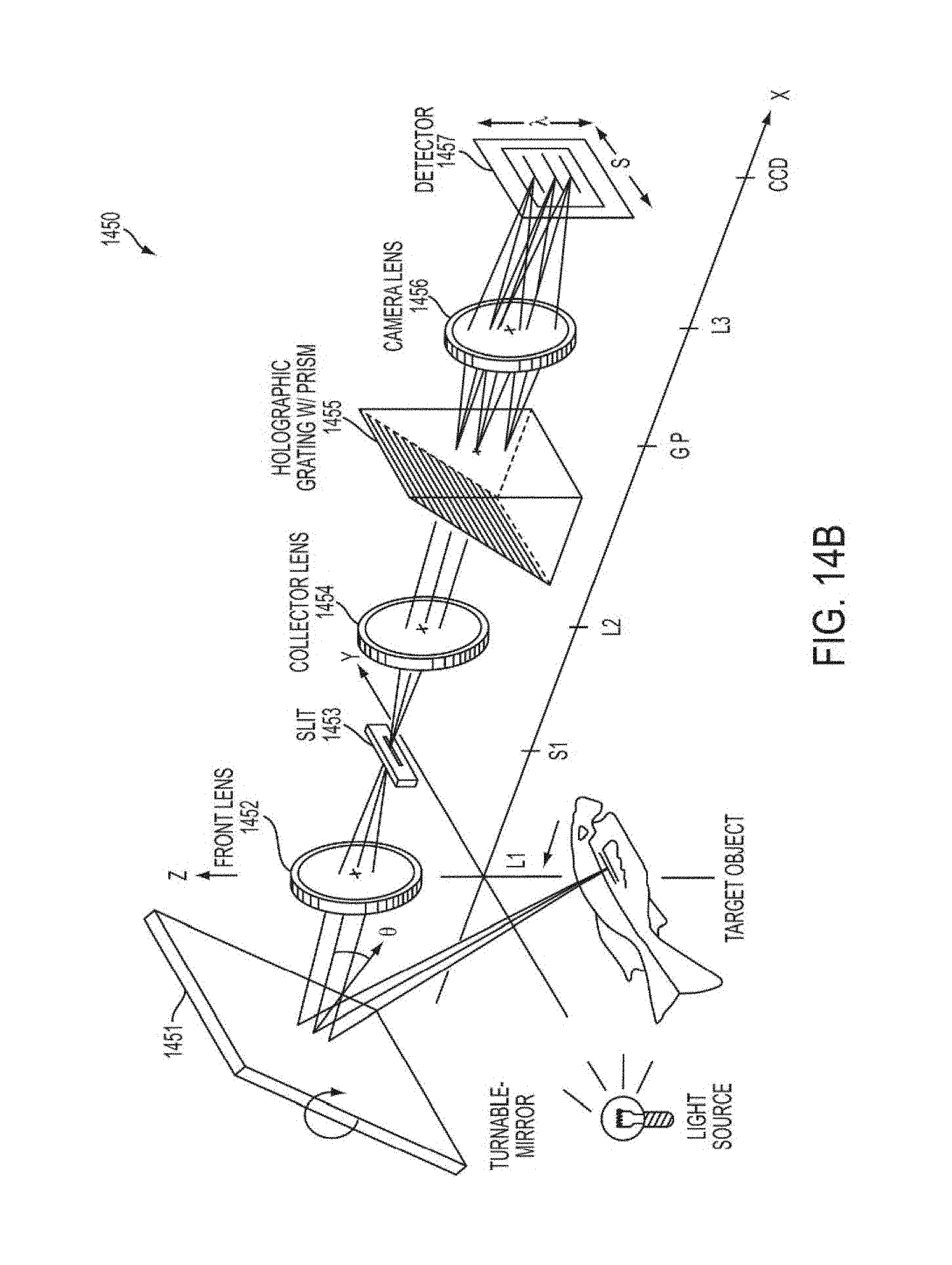
XML
uspto.report is an independent third-party trademark research tool that is not affiliated, endorsed, or sponsored by the United States Patent and Trademark Office (USPTO) or any other governmental organization. The information provided by uspto.report is based on publicly available data at the time of writing and is intended for informational purposes only.
While we strive to provide accurate and up-to-date information, we do not guarantee the accuracy, completeness, reliability, or suitability of the information displayed on this site. The use of this site is at your own risk. Any reliance you place on such information is therefore strictly at your own risk.
All official trademark data, including owner information, should be verified by visiting the official USPTO website at www.uspto.gov. This site is not intended to replace professional legal advice and should not be used as a substitute for consulting with a legal professional who is knowledgeable about trademark law.