Portable Electronic Device With Interface Reconfiguration Mode
VAN OS; Marcel ; et al.
U.S. patent application number 16/270902 was filed with the patent office on 2019-06-13 for portable electronic device with interface reconfiguration mode. The applicant listed for this patent is Apple Inc.. Invention is credited to Freddy Allen ANZURES, Imran CHAUDHRI, Greg CHRISTIE, Scott FORSTALL, Marcel VAN OS.
| Application Number | 20190179514 16/270902 |
| Document ID | / |
| Family ID | 40696344 |
| Filed Date | 2019-06-13 |

| United States Patent Application | 20190179514 |
| Kind Code | A1 |
| VAN OS; Marcel ; et al. | June 13, 2019 |
PORTABLE ELECTRONIC DEVICE WITH INTERFACE RECONFIGURATION MODE
Abstract
A portable electronic device displays a plurality of icons (e.g., graphical objects) in a region in a touch-sensitive display; detects a predefined user action, with respect to the touch-sensitive display, for initiating a predefined user interface reconfiguration process; and varies positions of one or more icons in the plurality of icons in response to detecting the predefined user action. The varying includes varying the positions of the one or more icons about respective average positions.
| Inventors: | VAN OS; Marcel; (San Francisco, CA) ; ANZURES; Freddy Allen; (San Francisco, CA) ; FORSTALL; Scott; (Los Altos, CA) ; CHRISTIE; Greg; (San Jose, CA) ; CHAUDHRI; Imran; (San Francisco, CA) | ||||||||||
| Applicant: |
|
||||||||||
|---|---|---|---|---|---|---|---|---|---|---|---|
| Family ID: | 40696344 | ||||||||||
| Appl. No.: | 16/270902 | ||||||||||
| Filed: | February 8, 2019 |
Related U.S. Patent Documents
| Application Number | Filing Date | Patent Number | ||
|---|---|---|---|---|
| 14710125 | May 12, 2015 | |||
| 16270902 | ||||
| 12364470 | Feb 2, 2009 | 9933913 | ||
| 14710125 | ||||
| 11459602 | Jul 24, 2006 | 7509588 | ||
| 12364470 | ||||
| 60755368 | Dec 30, 2005 | |||
| Current U.S. Class: | 1/1 |
| Current CPC Class: | G06F 9/451 20180201; G06F 3/04817 20130101; G06F 3/04842 20130101; G06F 9/44505 20130101; G06F 2203/04803 20130101; H04M 1/72563 20130101; H04M 2250/22 20130101; G06F 3/0482 20130101; G06F 3/04886 20130101 |
| International Class: | G06F 3/0481 20060101 G06F003/0481; G06F 3/0488 20060101 G06F003/0488; G06F 3/0482 20060101 G06F003/0482; G06F 3/0484 20060101 G06F003/0484 |
Claims
1. (canceled)
2. An electronic device, comprising: a touch-sensitive display; one or more processors; and memory storing one or more programs configured to be executed by the one or more processors, the one or more programs including instructions for: displaying a plurality of application icons on the touch-sensitive display in a normal mode of operation; while in the normal mode of operation and displaying the plurality of application icons, detecting a first finger gesture on a first application icon in the plurality of application icons, the first finger gesture being a tap gesture, the first application icon being at a first location on the touch-sensitive display; in response to detecting the first finger gesture on the first application icon, initiating the application that corresponds to the first application icon; while in the normal mode of operation and displaying the plurality of application icons, detecting a second finger gesture on the first application icon at the first location on the touch-sensitive display, the second finger gesture including a finger contact held on the first application icon for more than a predetermined period; in response to detecting the finger contact held on the first application icon for more than the predetermined period while in the normal mode of operation, entering a user interface reconfiguration mode, distinct from the normal mode of operation, wherein the user interface reconfiguration mode is maintained after the finger contact held on the first application icon for more than the predetermined period is broken; while in the user interface reconfiguration mode: detecting movement of a new finger contact from the first location on the touch-sensitive display to a second location on the touch-sensitive display; and moving the first application icon to the second location on the touch-sensitive display in accordance with the movement of the new finger contact.
3. The electronic device of claim 2, wherein the one or more programs further include instructions for: while in the user interface reconfiguration mode: displaying the first application icon in a manner different from that in the normal mode of operation.
4. The electronic device of claim 2, wherein the one or more programs further include instructions for: while in the user interface reconfiguration mode: displaying at least one application icon other than the first application icon in a manner different from that in the normal mode of operation.
5. The electronic device of claim 2, wherein each application icon in the plurality of application icons is capable of being repositioned on the touch-sensitive display while in the user interface reconfiguration mode.
6. The electronic device of claim 2, wherein moving the first application icon to the second location on the touch-sensitive display includes animating the first application icon to simulate floating of the first application icon on a surface corresponding to a surface of the touch-sensitive display.
7. The electronic device of claim 2, wherein the one or more programs further include instructions for: providing at least one of audible and tactile feedback when the first application icon has been moved.
8. The electronic device of claim 2, wherein the one or more programs further include instructions for: in response to detecting the second user input that includes movement of the finger contact from the first location on the touch-sensitive display to the second location on the touch-sensitive display, repositioning a second application icon from the second location to a third location on the touch-sensitive display to make room for the first application icon at the second location.
9. The electronic device of claim 2, wherein the one or more programs further include instructions for: upon moving the first application icon to the second location on the touch-sensitive display, removing one or more application icons from the plurality of application icons to prevent overlapping of the moved first application icon with any of the application icons in the plurality of application icons on the touch-sensitive display.
10. A method comprising: at an electronic device with a touch-sensitive display: displaying a plurality of application icons on the touch-sensitive display in a normal mode of operation; while in the normal mode of operation and displaying the plurality of application icons, detecting a first finger gesture on a first application icon in the plurality of application icons, the first finger gesture being a tap gesture, the first application icon being at a first location on the touch-sensitive display; in response to detecting the first finger gesture on the first application icon, initiating the application that corresponds to the first application icon; while in the normal mode of operation and displaying the plurality of application icons, detecting a second finger gesture on the first application icon at the first location on the touch-sensitive display, the second finger gesture including a finger contact held on the first application icon for more than a predetermined period; in response to detecting the finger contact held on the first application icon for more than the predetermined period while in the normal mode of operation, entering a user interface reconfiguration mode, distinct from the normal mode of operation, wherein the user interface reconfiguration mode is maintained after the finger contact held on the first application icon for more than the predetermined period is broken; while in the user interface reconfiguration mode: detecting movement of a new finger contact from the first location on the touch-sensitive display to a second location on the touch-sensitive display; and moving the first application icon to the second location on the touch-sensitive display in accordance with the movement of the new finger contact.
11. A non-transitory computer-readable storage medium storing one or more programs configured to be executed by one or more processors of an electronic device with a touch-sensitive display, the one or more programs including instructions for: displaying a plurality of application icons on the touch-sensitive display in a normal mode of operation; while in the normal mode of operation and displaying the plurality of application icons, detecting a first finger gesture on a first application icon in the plurality of application icons, the first finger gesture being a tap gesture, the first application icon being at a first location on the touch-sensitive display; in response to detecting the first finger gesture on the first application icon, initiating the application that corresponds to the first application icon; while in the normal mode of operation and displaying the plurality of application icons, detecting a second finger gesture on the first application icon at the first location on the touch-sensitive display, the second finger gesture including a finger contact held on the first application icon for more than a predetermined period; in response to detecting the finger contact held on the first application icon for more than the predetermined period while in the normal mode of operation, entering a user interface reconfiguration mode, distinct from the normal mode of operation, wherein the user interface reconfiguration mode is maintained after the finger contact held on the first application icon for more than the predetermined period is broken; while in the user interface reconfiguration mode: detecting movement of a new finger contact from the first location on the touch-sensitive display to a second location on the touch-sensitive display; and moving the first application icon to the second location on the touch-sensitive display in accordance with the movement of the new finger contact.
Description
RELATED APPLICATIONS
[0001] This application is a continuation of U.S. patent application Ser. No. 14/710,125, "Portable Electronic Device with Interface Reconfiguration Mode," filed May 12, 2015, which is a continuation of U.S. patent application Ser. No. 12/364,470, "Portable Electronic Device with Interface Reconfiguration Mode," filed Feb. 2, 2009, which is a continuation of U.S. patent application Ser. No. 11/459,602, "Portable Electronic Device with Interface Reconfiguration Mode," filed Jul. 24, 2006, now U.S. Pat. No. 7,509,588, which claims priority to U.S. Provisional Patent Application No. 60/755,368, filed Dec. 30, 2005, entitled "Portable Electronic Device with Interface Reconfiguration Mode," each of which is hereby incorporated by reference in its entirety.
TECHNICAL FIELD
[0002] The disclosed embodiments relate to user interfaces, and in particular, to user interfaces that use touch-sensitive displays and include an interface reconfiguration mode.
BACKGROUND
[0003] As portable devices become more compact, and the amount of information to be processed and stored increases, it has become a significant challenge to design a user interface that allows users to easily interact with the device. This is unfortunate since the user interface is the gateway through which users receive not only content but also responses to user actions or behaviors, including user attempts to access a device's features or tools. Some portable electronic devices (e.g., mobile phones) have resorted to adding more pushbuttons, overloading the functions of pushbuttons, or using complex menu systems to allow a user to access, store and manipulate data. These conventional user interfaces often result in complicated key sequences and menu hierarchies that must be memorized by the user.
[0004] Many conventional user interfaces, such as those that include physical pushbuttons, are also inflexible. This is unfortunate because it may prevent a user interface from being configured and/or adapted by either an application running on the portable device or by users. When coupled with the time consuming requirement to memorize multiple key sequences and/or menu hierarchies, such inflexibility is frustrating to many users.
[0005] Some conventional user interfaces can be configured by users, thereby allowing at least partial customization. Unfortunately, the process of modifying such conventional user interfaces is often as cumbersome and complicated as the use of the conventional user interface itself. In particular, the required behaviors during configuration of such conventional user interfaces are often counter intuitive and the corresponding indicators guiding user actions are often difficult to understand. These challenges are often a source of additional frustration for users.
[0006] Accordingly, there is a need for a more transparent and intuitive user interfaces for portable devices that enable a user to configure the user interface.
SUMMARY OF EMBODIMENTS
[0007] The above deficiencies and other problems associated with user interfaces for portable devices are reduced or eliminated by the disclosed portable electronic device, which includes an interface reconfiguration mode that intuitively allows a user to reposition displayed graphical objects.
[0008] One aspect of the invention is a method in which a portable electronic device displays a first plurality of icons (e.g., graphical objects) in a first region in a touch-sensitive display; detects a first predefined user action, with respect to the touch-sensitive display, for initiating a predefined user interface reconfiguration process; and varies positions of one or more icons in the first plurality of icons in response to detecting the first predefined user action. The varying includes varying the positions of the one or more icons about respective average positions.
[0009] The varying may include animating the one or more icons to simulate floating of the one or more icons on a surface corresponding to a surface of the touch-sensitive display.
[0010] The varying position of a respective icon in the one or more icons may correspond to an equation of motion in a plane substantially coincident with the touch-sensitive display. The equation of motion may have a coefficient of friction less than a threshold, a non-zero initial velocity for the respective icon, a non-zero angular velocity, and/or a restoring force about the respective average position of the respective icon such that the position of the respective icon oscillates in a region substantially centered on the respective average position of the respective icon. In some embodiments, the respective icon rotates about the respective average position of the respective icon while maintaining a fixed orientation with respect to the touch-sensitive display.
[0011] In some embodiments, the method further includes: detecting a user making a point of contact with the touch-sensitive display at a first position corresponding to a first icon in the one or more icons and detecting movement of the point of contact to a second position of the touch-sensitive display; and responding to detecting the point of contact and detecting movement of the point of contact by displaying movement of the first icon to the second position of the touch-sensitive display, and displaying the first icon at the second position.
[0012] A second icon in the one or more icons may be moved from a respective initial position to a respective new position when the second position of the first icon at least partially overlaps with the respective initial position of the second icon. The position of the first icon may be fixed at the second position in response to detecting a second predefined user action, with respect to the touch-sensitive display, for terminating the predefined user interface reconfiguration process.
[0013] The aforementioned methods may be performed by a portable electronic device having a touch-sensitive display with a graphical user interface (GUI), one or more processors, memory and one or more modules, programs or sets of instructions stored in the memory for performing these methods. In some embodiments, the portable electronic device provides a plurality of functions, including wireless communication.
[0014] Instructions for performing the aforementioned methods may be included in a computer program product configured for execution by one or more processors.
BRIEF DESCRIPTION OF THE DRAWINGS
[0015] For a better understanding of the aforementioned embodiments of the invention as well as additional embodiments thereof, reference should be made to the Description of Embodiments below, in conjunction with the following drawings in which like reference numerals refer to corresponding parts throughout the figures.
[0016] FIG. 1 is a flow diagram of one embodiment of a position adjustment process for a portable electronic device.
[0017] FIG. 2A is an illustration of one embodiment of a portable electronic device responsive to touch input for adjustment of the position of one or more icons.
[0018] FIG. 2B is an illustration of one embodiment of a portable electronic device responsive to touch input for adjustment of the position of one or more icons.
[0019] FIG. 2C is an illustration of one embodiment of a portable electronic device responsive to touch input for adjustment of the position of one or more icons.
[0020] FIG. 2D is an illustration of one embodiment of a portable electronic device responsive to touch input for adjustment of the position of one or more icons.
[0021] FIG. 2E is an illustration of one embodiment of a portable electronic device responsive to touch input for adjustment of the position of one or more icons.
[0022] FIG. 3A is an illustration of one embodiment of a portable electronic device responsive to touch input for adjustment of the position of one or more icons.
[0023] FIG. 3B is an illustration of one embodiment of a portable electronic device responsive to touch input for adjustment of the position of one or more icons.
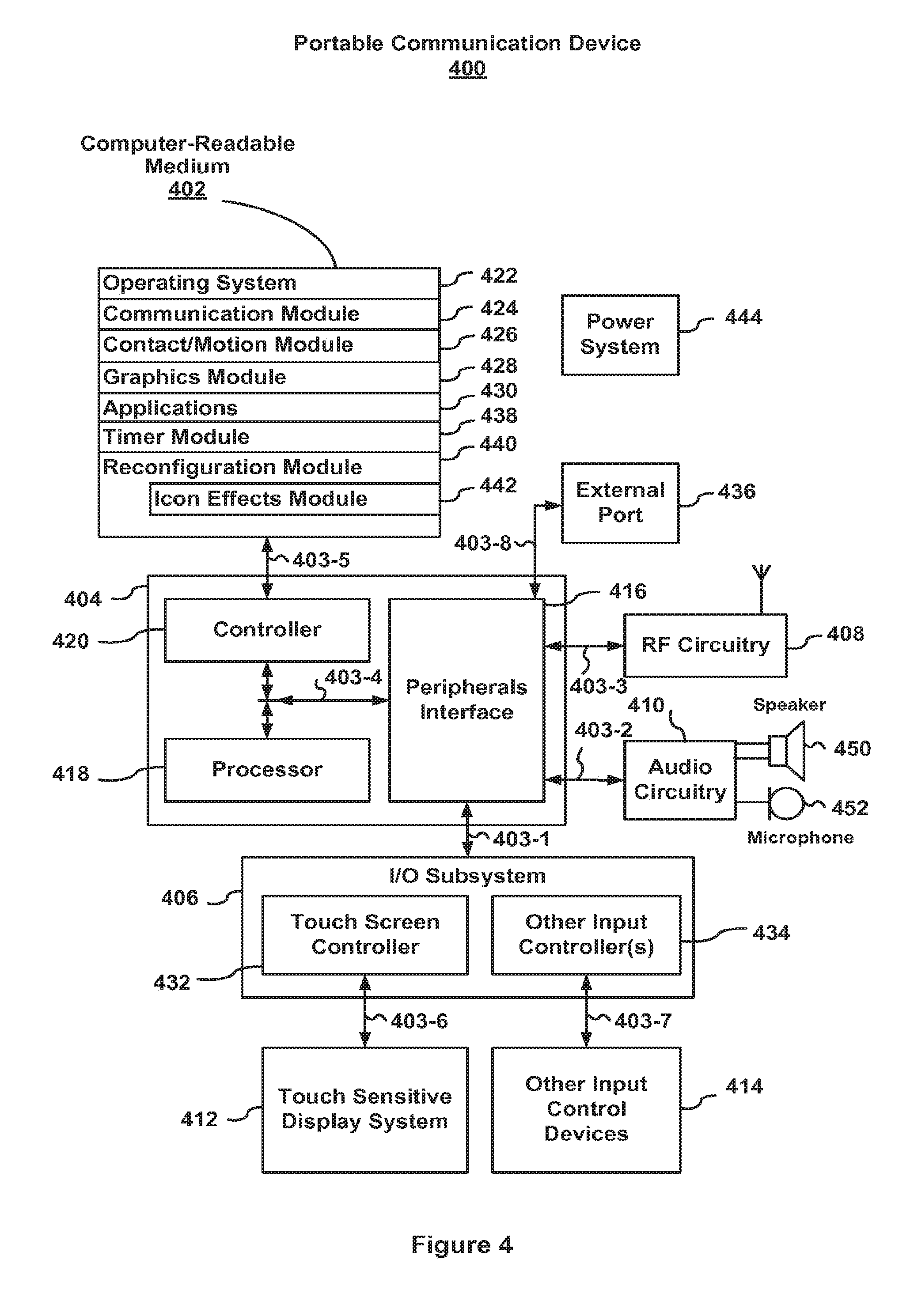
[0024] FIG. 4 is a block diagram of one embodiment of a portable electronic device.
DESCRIPTION OF EMBODIMENTS
[0025] Reference will now be made in detail to embodiments, examples of which are illustrated in the accompanying drawings. In the following detailed description, numerous specific details are set forth in order to provide a thorough understanding of the present invention. However, it will be apparent to one of ordinary skill in the art that the present invention may be practiced without these specific details. In other instances, well-known methods, procedures, components, and circuits have not been described in detail so as not to unnecessarily obscure aspects of the embodiments.
Overview of the Interface Reconfiguration Mode
[0026] Attention is directed towards embodiments of portable electronic devices, including portable communications devices, that have graphical user interfaces (GUIs). The portable devices include an interface reconfiguration mode. In response to a user initiating the interface reconfiguration mode, positions of one or more icons displayed on the portable device may be varied about respective average positions. The varying of the positions of the one or more icons may include animating the one or more icons to simulate floating of the one or more icons on a surface corresponding to a surface of a display in the portable device. The display may be a touch-sensitive display, which responds to physical contact by a stylus or one or more fingers at one or more contact points. While the following embodiments may be equally applied to other types of displays, a touch-sensitive display is used as an illustrative example.
[0027] The varying of the positions of the one or more icons may intuitively indicate to the user that the positions of the one or more icons may be reconfigured by the user. The user may modify, adapt and/or reconfigure the positions of the one or more icons. In embodiments where the portable device includes a touch-sensitive display, the user may make contact with the touch-sensitive display proximate to a respective icon at a first position. Upon making contact with the touch-sensitive display, the respective icon may cease varying its position. The user may drag the respective icon to a second position. Upon breaking contact with the touch-sensitive display, the respective icon may resume varying its position. In some embodiments, the respective icon can be "thrown," so that the final position of the respective icon is different from the point at which the icon is released. In this embodiment, the final position can depend on a variety of factors, such as the speed of the "throw," the parameters used in a simulated equation of motion for the "throw" (e.g., coefficient of friction), and/or the presence of a lay out grid with simulated attractive forces. In some embodiments, the display may include two regions. During the interface reconfiguration mode, positions of one or more icons displayed in the first region may be varied while positions of one or more icons displayed in the second region may be stationary.
[0028] The user may similarly modify, adapt and/or reconfigure the positions of additional icons during the interface reconfiguration mode. When the user has completed these changes (at least for the time being), he or she may terminate the interface reconfiguration mode. In response to this user action, the portable device may return to a normal mode of operation and the varying of the displayed positions of the one or more icons will cease.
[0029] The user may initiate or terminate the interface reconfiguration process by selecting one or more appropriate physical buttons on the portable device, by a gesture (such as making contact and swiping one or more fingers across the touch-sensitive display or making contact and holding for more than a predefined time period) and/or by selecting one or more soft buttons (such as one or more icons that are displayed on the touch-sensitive display). As used herein, a gesture is a motion of the object/appendage making contact with the touch screen display surface. In some embodiments, the interface reconfiguration process terminates a pre-defined time after the interface reconfiguration process is initiated, i.e., there is a time out.
[0030] The one or more icons displayed on the portable device may be graphical objects. In some embodiments, the one or more icons may be widgets, which are combinations of states and procedures that constitute on-screen representations of controls that may be manipulated by the user, such as bars, buttons and text boxes. In an exemplary embodiment, the one or more icons correspond to application programs (email, browser, address book, etc.) that may be selected by the user by contacting the touch-sensitive display proximate to an icon of interest.
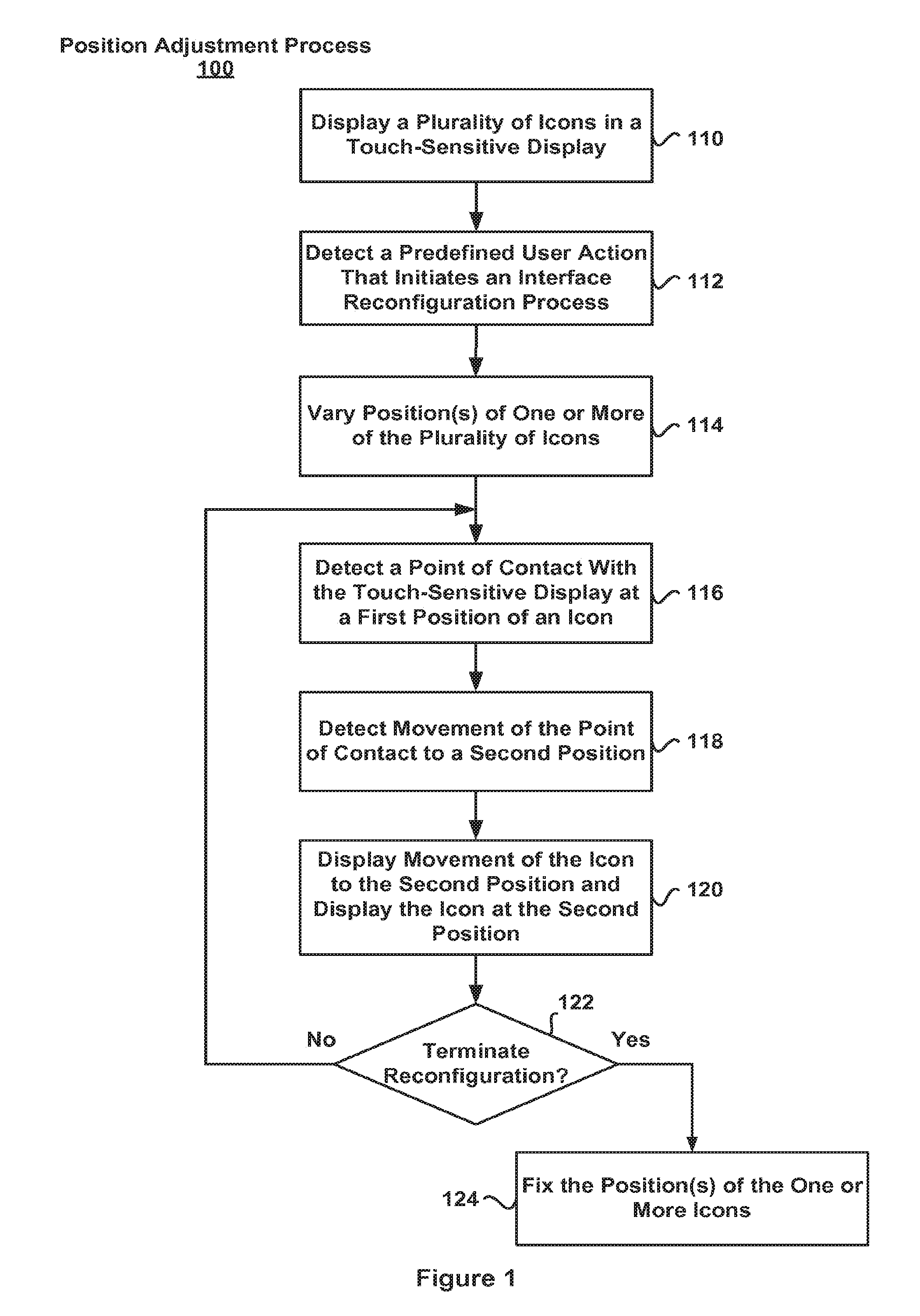
[0031] FIG. 1 is a flow diagram of one embodiment of a position adjustment process 100 for a portable electronic device. While the position adjustment process 100 described below includes a number of operations that appear to occur in a specific order, it should be apparent that the process 100 can include more or fewer operations, which can be executed serially or in parallel (e.g., using parallel processors or a multi-threading environment), an order of two or more operations may be changed and/or two or more operations may be combined into a single operation.
[0032] In the position adjustment process 100, a plurality of icons are displayed in a GUI in a touch-sensitive display (110). A first predefined user action that initiates an interface reconfiguration process is detected (112). Exemplary predefined user actions include selecting a physical button on the portable device, making a predefined gesture on the touch screen display surface, or selecting a soft button. Position(s) of one or more of the plurality of displayed icons are varied (114). A point of contact with the touch-sensitive display at a first position of a respective icon is detected (116). Movement of the point of contact to a second position is detected (118). Movement of the respective icon to the second position is displayed and the respective icon is displayed at the second position (120).
[0033] If a second predefined user action that terminates the interface reconfiguration process is detected (122-yes), the position(s) of the one or more icons is fixed (124). Exemplary predefined user actions include selecting or deselecting a physical button on the portable device, making another predefined gesture on the touch screen display surface, or selecting or deselecting a soft button. The fixed position(s) may correspond to a respective average position(s) for the one or more icons. If a second pre-defined user action that terminates the interface reconfiguration process is not detected (122-no), the process may continue when a point of contact proximate to the same or another icon is detected (116).
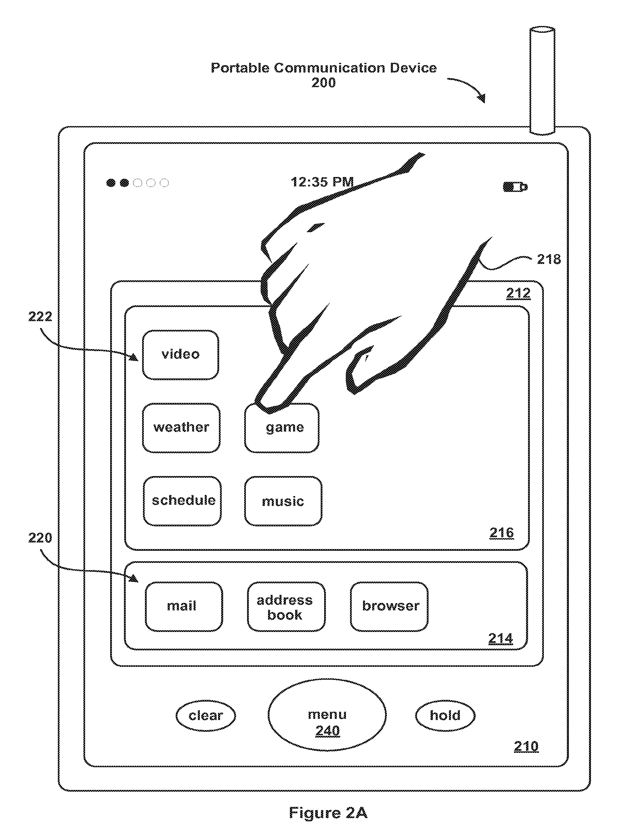
[0034] FIG. 2A is an illustration of one embodiment of a portable electronic device 200 responsive to touch input for adjustment of the position of one or more icons. The portable electronic device 200 includes a touch-sensitive display with a GUI 210. The display surface is transparent to allow various graphical objects to be displayed to the user (e.g., widgets). In some embodiments, the GUI 210 is divided into multiple sections or windows. For example, a region 212 of GUI 210 may include a tray 216 for holding icons or graphical objects 222 representing functions that are frequently used by the user (e.g., video, weather, schedule, game, music, etc.) and a tray 214 for holding icons or graphical objects 220 representing functions that are used less frequently by the user (e.g., mail, address book, browser, etc.). The GUI 210 may also include graphical objects corresponding to high-level functions of the portable electronic device 200. For example, various objects and/or images may be presented and changed in GUI 210 by pressing a menu button 240. In embodiments that include a mobile phone, dedicated graphical objects can be presented in GUI 210 representing traditional voice and data service operations (e.g., hold, clear, etc.).
[0035] The user may interact with the portable communications device 200 by making contact with the display surface with GUI 210 using a stylus, a finger 218 (not drawn to scale in FIG. 2) or more than one finger. For example, the user may make contact with the display surface at a position of one of the icons 222 (direct contact), thereby activating the function or application program corresponding to that icon. In some embodiments, the icon 222 is activated when the user makes contact at the position of the icon and then breaks contact (for example, a tapping gesture). In some embodiments, the contact with the display surface used to activate the icon may not be at the position of the icon 222. Instead, contact may be proximate to the icon 222 (indirect contact). The latter technique is similar to "hot spots" used with Web pages and other computer user interfaces.
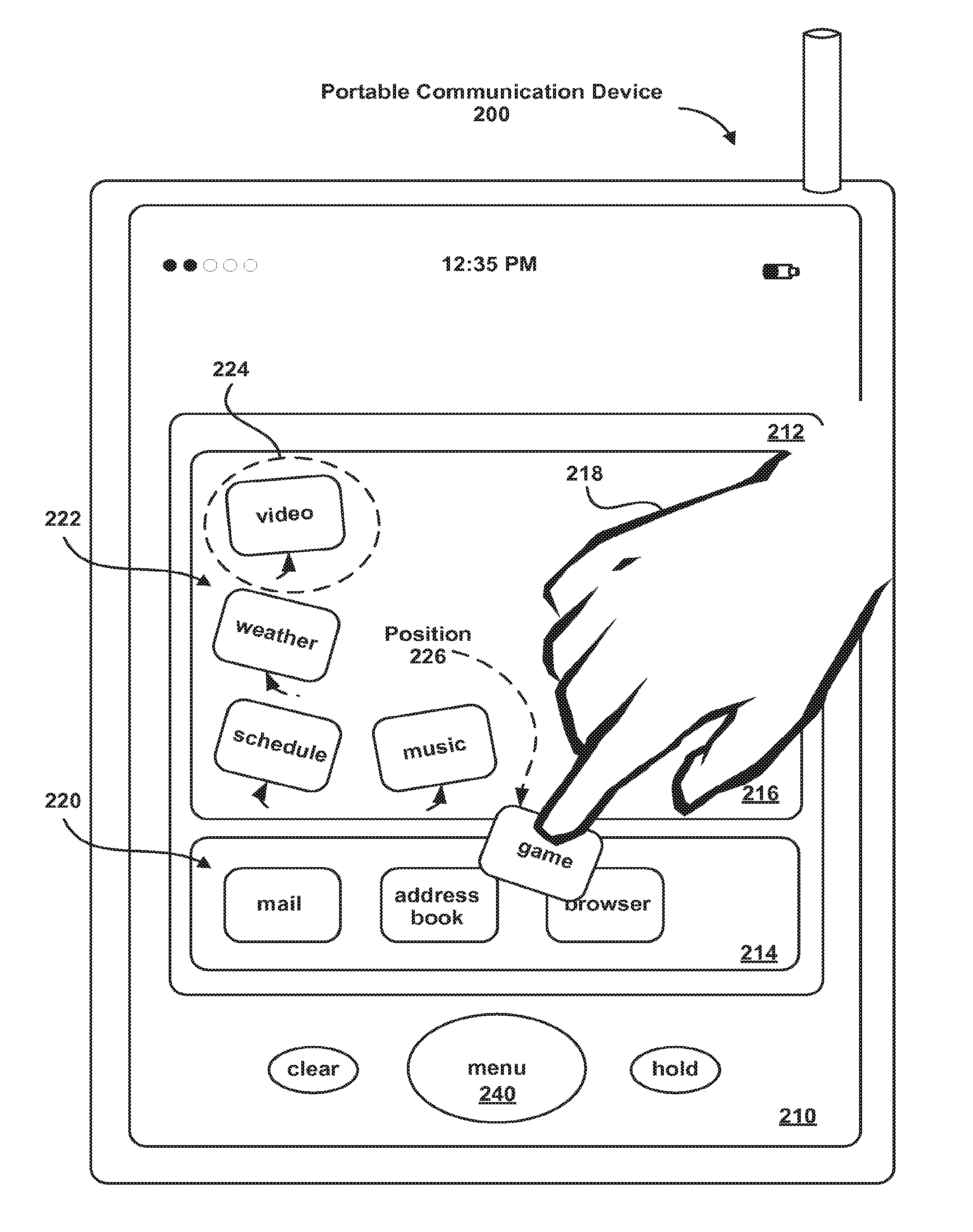
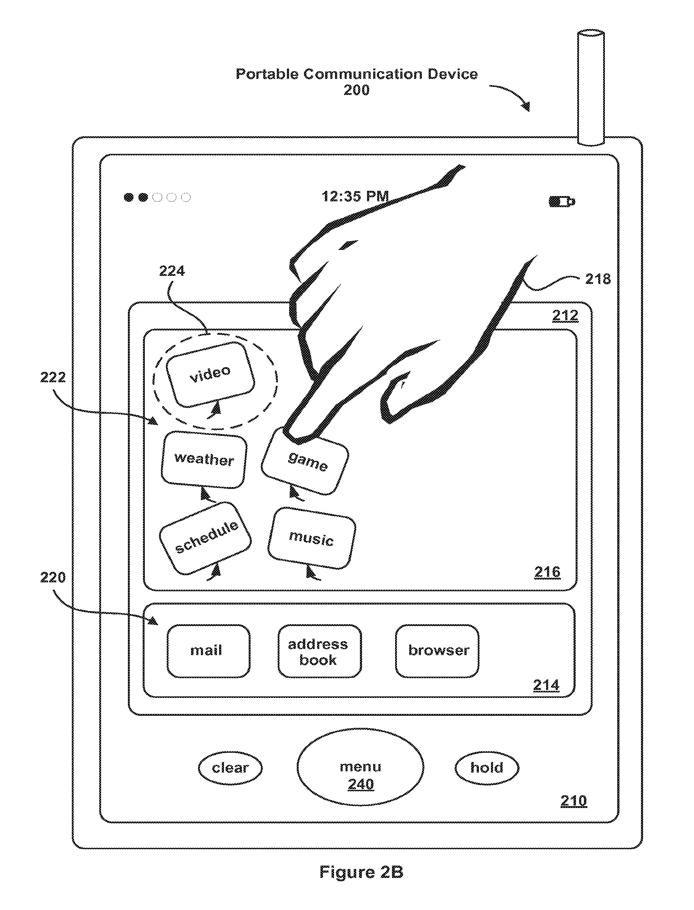
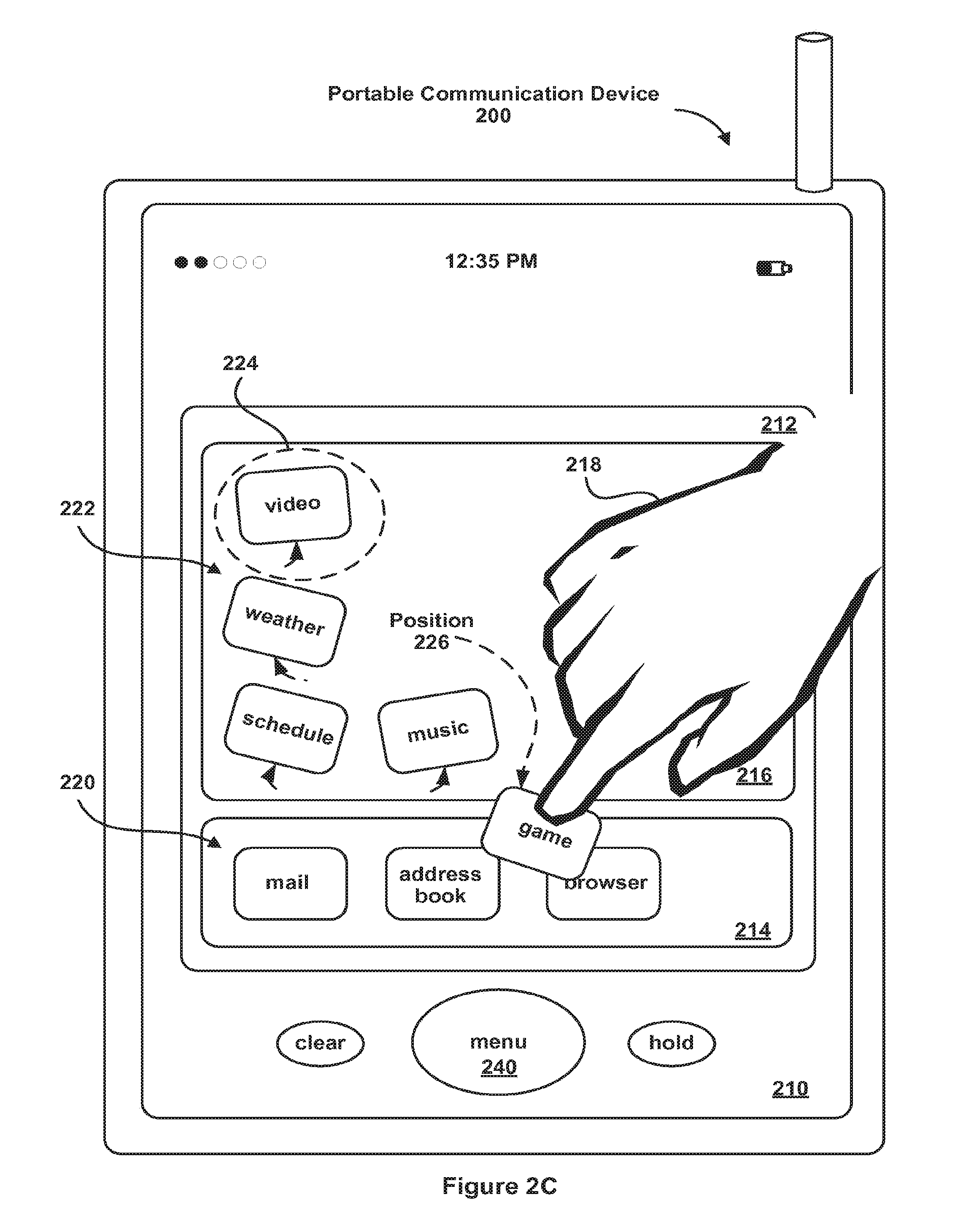
[0036] FIGS. 2B-D show the portable electronic device 200 during the interface reconfiguration mode. After the interface reconfiguration mode is initiated, the display of one or more of the icons 222 in the tray 216 is modified from the previous stationary positions to time-varying positions. As noted previously, the display may include animating one or more of the icons 222 to simulate floating of one or more of the icons 222 on a surface corresponding to the display surface. For example, the animated varying of the positions of one or more of the icons 222 during the interface reconfiguration mode may resemble that of a hockey puck in an air hockey game. The displayed position(s) of a respective icon in the icons 222 may be varied in a region 224 centered on the average position of the respective icon.
[0037] While FIG. 2B-2D illustrates movement of one or more of the icons 222 in the tray 216, in other embodiments positions of one or more of the icons 220 in another region of GUI 210, such as tray 214, may be varied separately or in addition to those of one or more of the icons 222 in tray 216.
[0038] The time-varying position(s) of one or more of the icons 222 intuitively indicate to the user that the positions of one or more of the icons 222 may be modified. This is illustrated in FIGS. 2C-D, which show the portable electronic device 200 during the interface reconfiguration mode. The user makes contact, either direct or indirect, with one of the icons that is moving at a position 226 and moves the point of contact across the display surface with GUI 210. The contact and the motion are detected by the portable electronic device 200. As a consequence, the displayed icon, in this example corresponding to a game, is moved accordingly.
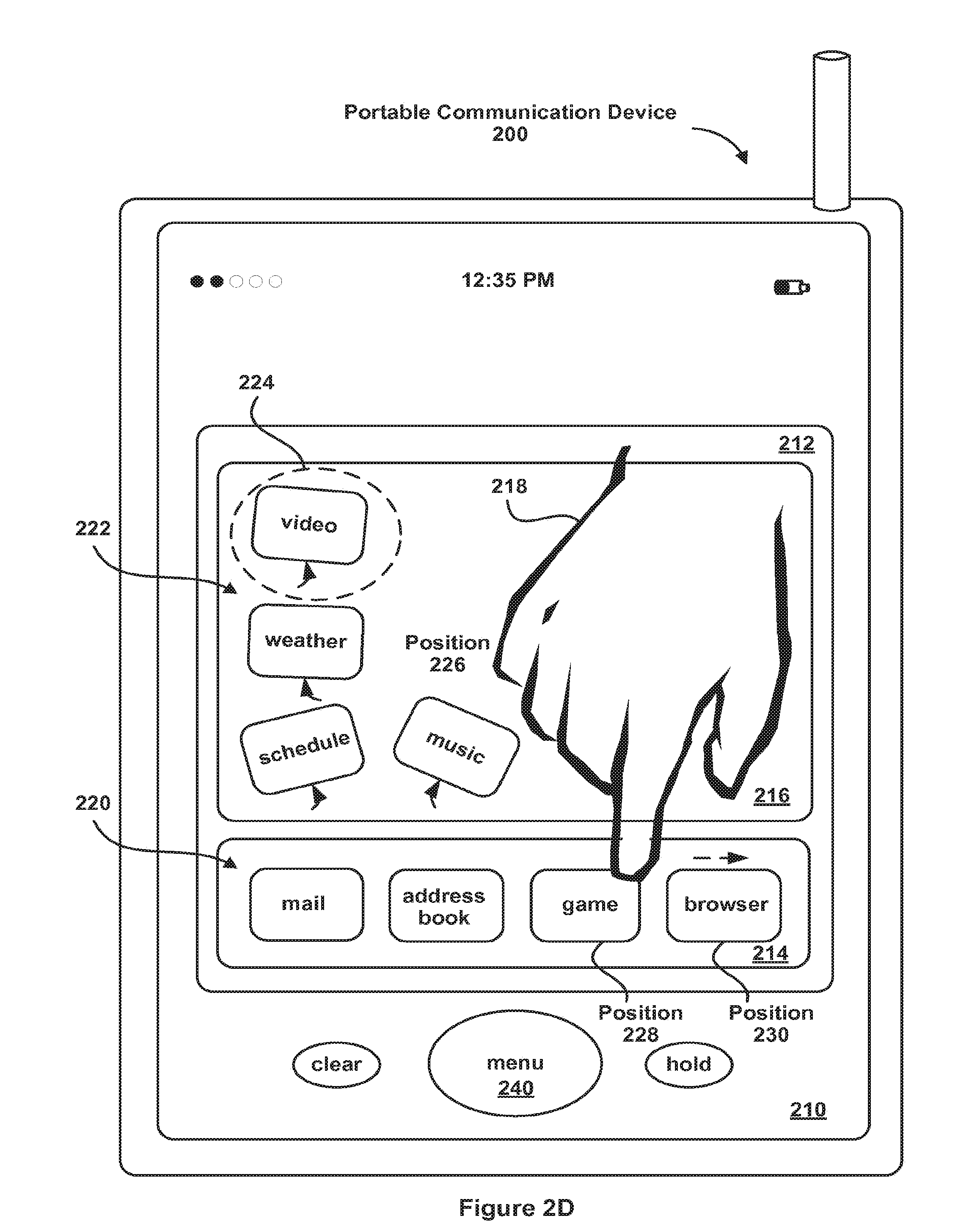
[0039] As shown in FIG. 2D, the user moves the game icon to position 228 and breaks contact with the display surface. The game icon is now displayed at the position 228. While the displayed position of the game icon is shown as stationary in FIG. 2D, in some embodiments the position of the game icon may be varied once the user breaks contact with the display surface. In some embodiments, only icons displayed in one or more subsections of the GUI 210 are displayed with a varying position during the interface reconfiguration mode. Thus, if the game icon had been dragged to another position in the tray 216, it may be displayed with a varying position after the user breaks contact with the display. In some embodiments, the device may provide audio and/or tactile feedback when an icon is moved to a new position, such as an audible chime and/or a vibration.
[0040] FIG. 2D also illustrates the optional displacement of the browser icon to position 230. The browser icon was displaced from its initial position 228 to its new position 230 due to at least partial overlap with the game icon, i.e., when the portable electronic device 200 determined that the user positioned the game icon over the browser icon, the displayed position of the browser icon was changed.
[0041] In other embodiments, an icon may be evicted or removed from the tray 214 when an additional icon, such as the music icon, is added to the tray 214. For example, the tray 214 may be configured to accommodate a finite number of icons, such as 4 icons. If an additional icon is added to the tray 214, a nearest icon to the additional icon or an icon that at least partially overlaps the additional icon may be evicted or removed from the tray 214. In some embodiments, the evicted icon floats or zooms from its position in tray 214 to a new position in tray 216, where it may join a sorted list of icons. In some embodiments, if the eviction process is not completed (e.g., the additional icon is not added to tray 214), the evicted icon may halt its progress towards its new position in tray 216 and return to its position in tray 214.
[0042] FIG. 2E illustrates the portable electronic device 200 after the interface reconfiguration mode has been terminated or has terminated (due to a time out). The icons in GUI 210 have stationary positions. The game icon and the browser icon arc displayed in their new positions in the tray 214.
[0043] The animated effects during the interface reconfiguration mode, such as the varying position(s) of one or more of the icons 222, may be in accordance with corresponding equations of motion for one or more of the icons in a plane substantially coincident with the display surface with GUI 210. The equations of motion may have a coefficient of friction less than a threshold allowing the simulation and/or animation of floating or sliding of one or more of the icons. The equation of motion for the respective icon may have a non-zero initial velocity, a non-zero angular velocity, and/or a restoring force about the respective average position of the respective icon such that the position of the respective icon oscillates in the region 224 (FIG. 2D) substantially centered on the respective average position of the respective icon.
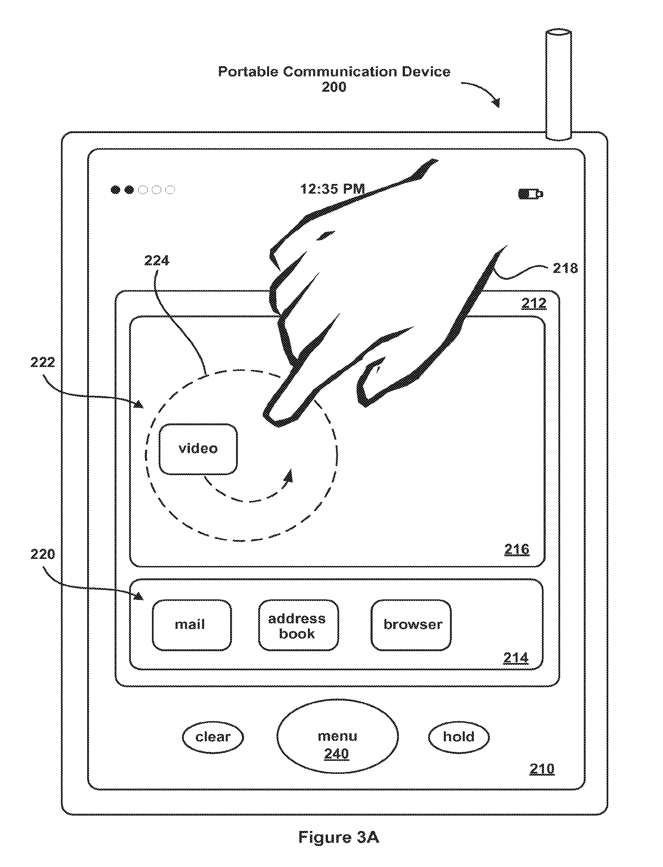
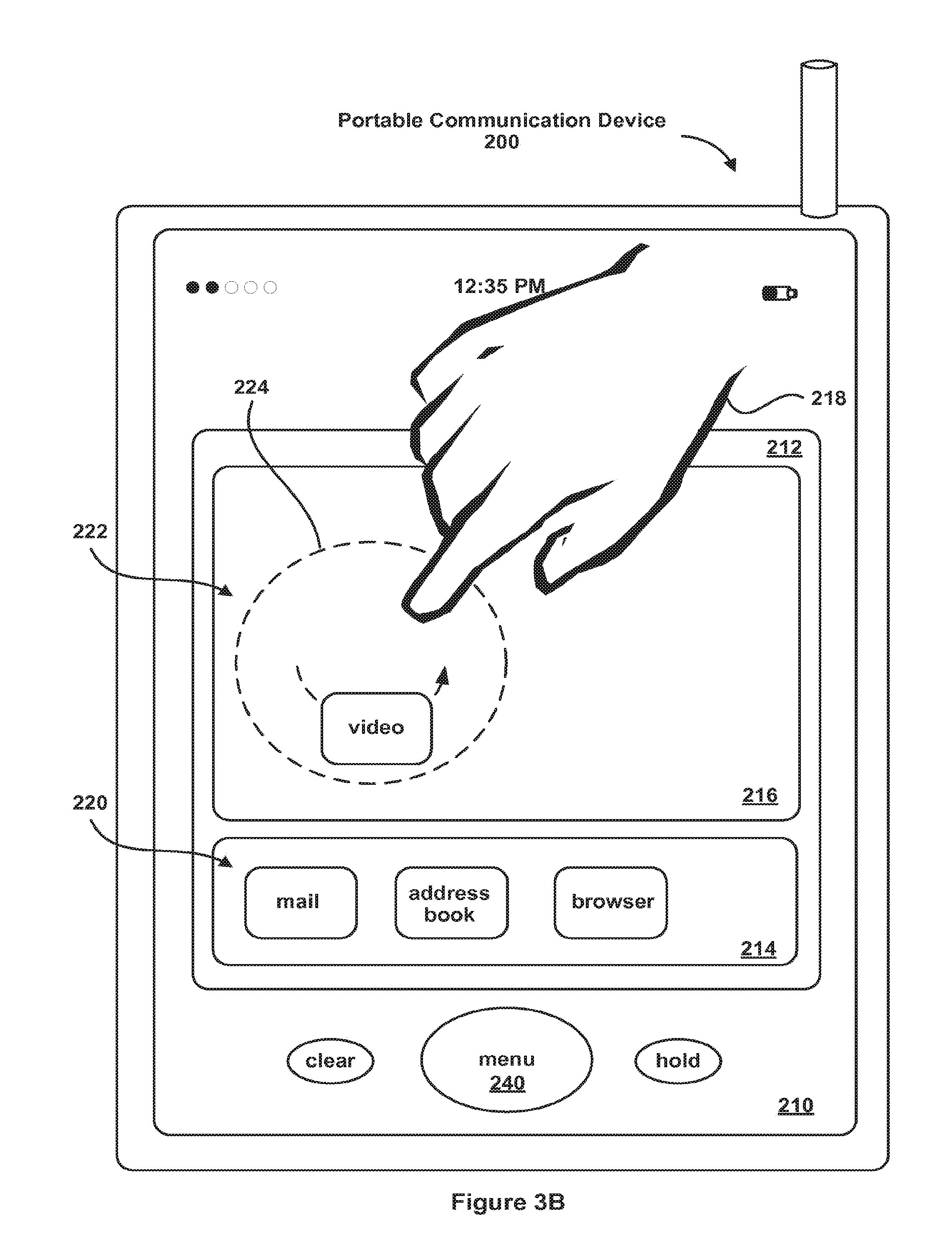
[0044] In some embodiments, the position of the respective icon may be varied during the interface reconfiguration mode in such a way that the respective icon rotates about the respective average position of the respective icon while maintaining a fixed orientation with respect to the GUI 210 and the portable electronic device 200. This is illustrated in FIGS. 3A and 3B, which show the portable electronic device 200 during the interface reconfiguration mode. In this example, the position of the video icon 222 in tray 216 is varied in such a way that it maintains a fixed orientation in region 224. This may make it easier for the user to determine the function of the respective icon during the interface reconfiguration mode.
Portable Electronic Device Architecture
[0045] Attention is now directed towards embodiments of the portable electronic device architecture. FIG. 4 is a block diagram of one embodiment of portable electronic device. A portable electronic device 400 generally includes one or more computer-readable mediums 402, a processing system 404, an Input/Output (I/O) subsystem 406, radio frequency (RF) circuitry 408 and audio circuitry 410. These components may be coupled by one or more communication buses or signal lines 403. The device 400 can be any portable electronic device, including but not limited to a handheld computer, a tablet computer, a mobile phone, a media player, personal digital assistant (PDA) and the like, including a combination of two or more of these items.
[0046] It should be apparent that the architecture shown in FIG. 4 is only one example of an architecture for the portable electronic device 400, and that the device 400 could have more or fewer components than shown, or a different configuration of components. The various components shown in FIG. 4 can be implemented in hardware, software, or a combination of both hardware and software, including one or more signal processing and/or application specific integrated circuits. The RF circuitry 408 is used to send and receive information over a wireless link or network to one or more other devices and includes well-known circuitry for performing this function, including but not limited to an antenna system, an RF transceiver, one or more amplifiers, a tuner, one or more oscillators, a digital signal processor, a CODEC chipset, memory, etc. In some embodiments, the RF circuitry 408 is capable of establishing and maintaining communications with other devices using one or more communications protocols, including but not limited to time division multiple access (TDMA), code division multiple access (CDMA), global system for mobile communications (GSM), Enhanced Data GSM Environment (EDGE), wideband code division multiple access (W-CDMA), Wi-Fi (such as IEEE 802.11a, IEEE 802.11b, IEEE 802.11g and/or IEEE 802.11n), Bluetooth, Wi-MAX, voice over Internet Protocol (VoIP), a protocol for email, instant messaging, and/or a short message service (SMS), or any other suitable communication protocol, including communication protocols not yet developed as of the filing date of this document.
[0047] The RF circuitry 408 and the audio circuitry 410 are coupled to the processing system 404 via the peripherals interface 416. The interface 416 includes various known components for establishing and maintaining communication between peripherals and the processing system 404. The audio circuitry 410 is coupled to an audio speaker 450 and a microphone 452 and includes known circuitry for processing voice signals received from interface 416 to enable a user to communicate in real-time with other users. In some embodiments, the audio circuitry 410 includes a headphone jack (not shown). Voice and data information received by the RF circuitry 408 and the audio circuitry 410 (e.g., in speech recognition or voice command applications) is sent to one or more processors 418 via the peripherals interface 416. The one or more processors 418 are configurable to process various data formats for one or more applications programs 430 stored on the medium 402.
[0048] Note that the term "data" includes but is not limited to text, graphics, Web pages, JAVA applets, widgets, emails, instant messages, voice, digital images or video, widgets, MP3s, etc., which can be used by one or more applications programs 430 stored on the medium 402 (e.g., Web browser, email, etc.). In some embodiments, the device 400 is capable of uploading and downloading various data from the Internet over a wireless network or an external port 436, such as files, songs, digital images, videos, emails, widgets, instant messages and the like.
[0049] The peripherals interface 416 couples the input and output peripherals of the device to the processor 418 and the computer-readable medium 402. The one or more processors 418 communicate with the one or more computer-readable mediums 402 via a controller 420. The computer-readable medium 402 can be any device or medium that can store code and/or data for use by the one or more processors 418. The medium 402 can include a memory hierarchy, including but not limited to cache, main memory and secondary memory. The memory hierarchy can be implemented using any combination of RAM (e.g., SRAM, DRAM, DDRAM), ROM, FLASH, magnetic and/or optical storage devices, such as disk drives, magnetic tape, CDs (compact disks) and DVDs (digital video discs). The medium 402 may also include a transmission medium for carrying information-bearing signals indicative of computer instructions or data (with or without a carrier wave upon which the signals are modulated). For example, the transmission medium may include a communications network, including but not limited to the Internet (also referred to as the World Wide Web), intranet(s), Local Area Networks (LANs), Wide Local Area Networks (WLANs), Storage Area Networks (SANs), Metropolitan Area Networks (MAN) and the like.
[0050] The one or more processors 418 run various software components stored in the medium 402 to perform various functions for the device 400. In some embodiments, the software components include an operating system 422, a communication module (or set of instructions) 424, a contact/motion module (or set of instructions) 426, a graphics module (or set of instructions) 428, one or more applications (or set of instructions) 430, a timer module (or set of instructions) 438 and a reconfiguration module (or set of instructions) 440.
[0051] The operating system 422 (e.g., Darwin, RTXC, LINUX, UNIX, OS X, WINDOWS, or an embedded operating system such as VxWorks) includes various procedures, sets of instructions, software components and/or drivers for controlling and managing general system tasks (e.g., memory management, storage device control, power management, etc.) and facilitates communication between various hardware and software components.
[0052] The communication module 424 facilitates communication with other devices over one or more external ports 436 or via RF circuitry 408 and includes various software components for handling data received from the RF circuitry 408 and/or the external port 436. The external port 436 (e.g., USB, FireWire.TM., etc.) is adapted for coupling directly to other devices or indirectly over a network (e.g., the Internet, wireless LAN, etc.).
[0053] The graphics module 428 includes various known software components for rendering, animating and displaying graphical objects on a display surface of a touch-sensitive display system 412. Note that the term "graphical object" includes any object that can be displayed to a user, including without limitation text, web pages, icons, digital images, animations and the like.
[0054] The one or more applications 430 can include any applications installed on the device 400, including without limitation, a browser, address book, contact list, email, instant messaging, word processing, keyboard emulation, widgets, JAVA-enabled applications, encryption, digital rights management, voice recognition, voice replication, location determination capability (such as that provided by the global positioning system (GPS)), a music player (which plays back recorded music stored in one or more files, such as MP3 or AAC files), etc.
[0055] In some embodiments, the device 400 may include the functionality of an MP3 player, such as an iPod (trademark of Apple Computer, Inc.). The device 400 may, therefore, include a 36-pin connector that is compatible with the iPod. In some embodiments, the device 400 may include one or more optional optical sensors (not shown), such as CMOS or CCD image sensors, for use in imaging applications.
[0056] The contact/motion module 426 includes various software components for performing various tasks associated with the touch-sensitive display system 412, as previously described with respect to the embodiments in FIGS. 1-3.
[0057] The timer module 438 is a software timer used with the interface reconfiguration process 100 (FIG. 1). The timer module 438 can also be implemented in hardware.
[0058] The reconfiguration module 440 may include an icon effects module (or a set of instructions) 442. The icon effects module 442 may include animation for the icons during the interface reconfiguration mode. In some embodiments, the icon effects module 442 may be included in the graphics module 428.
[0059] The I/O subsystem 406 is coupled to the touch-sensitive display system 412 and one or more other physical control devices 414 (e.g., pushbuttons, switches, dials, LEDs, etc.) for controlling or performing various functions, such as power control, speaker volume control, ring tone loudness, keyboard input, scrolling, hold, menu, screen lock, clearing and ending communications and the like. The touch-sensitive display 412 communicates with the processing system 404 via the touch sensitive screen controller 432, which includes various components for processing user input (e.g., scanning hardware). The one or more other input controllers 434 receives/sends electrical signals from/to the other input or control devices 414. The other input/control devices 414 may include physical buttons (e.g., push buttons, rocker buttons, etc.), dials, slider switches, sticks, and so forth.
[0060] The touch-sensitive display 412 displays visual output to the user in a GUI. The visual output may include text, graphics, video, and any combination thereof. Some or all of the visual output may correspond to user-interface objects. The touch-sensitive display 412 may also accept input from the user based on haptic and/or tactile contact. The touch-sensitive display 412 forms a touch-sensitive surface that accepts user input. The touch-sensitive display 412 and the touch screen controller 432 (along with any associated modules and/or sets of instructions in the medium 402) detects contact (and any movement or release of the contact) on the touch-sensitive display 412 and converts the detected contact into interaction with user-interface objects, such as one or more soft keys, that are displayed on the touch screen when the contact occurs. In an exemplary embodiment, a point of contact between the touch-sensitive display 412 and the user corresponds to one or more digits of the user. The touch-sensitive display 412 may use LCD (liquid crystal display) technology, or LPD (light emitting polymer display) technology, although other display technologies may be used in other embodiments. The touch-sensitive display 412 and touch screen controller 432 may detect contact and any movement or release thereof using any of a plurality of touch sensitivity technologies, including but not limited to capacitive, resistive, infrared, and surface acoustic wave technologies, as well as other proximity sensor arrays or other elements for determining one or more points of contact with the touch-sensitive display 412.
[0061] The touch-sensitive display may be analogous to the multi-touch sensitive tablets described in the following U.S. Pat. No. 6,323,846 (Westerman et al.), U.S. Pat. No. 6,570,557 (Westerman et al.), and/or U.S. Pat. No. 6,677,932 (Westerman), and/or U.S. Patent Publication 2002/0015024A1, each of which is hereby incorporated by reference. However, the touch screen 126 displays visual output from the portable device, whereas touch sensitive tablets do not provide visual output. The touch-sensitive display 412 may have a resolution in excess of 100 dpi. In an exemplary embodiment, the touch-sensitive display 412 may have a resolution of approximately 168 dpi. The user may make contact with the touch-sensitive display 412 using any suitable object or appendage, such as a stylus, pen, finger, and so forth.
[0062] In some embodiments, in addition to the touch screen, the device 400 may include a touchpad (not shown) for activating or deactivating particular functions. In some embodiments, the touchpad is a touch-sensitive area of the device that, unlike the touch screen, does not display visual output. The touchpad may be a touch-sensitive surface that is separate from the touch-sensitive display 412 or an extension of the touch-sensitive surface formed by the touch-sensitive display 412.
[0063] The device 400 also includes a power system 444 for powering the various hardware components. The power system 444 can include a power management system, one or more power sources (e.g., battery, alternating current (AC)), a recharging system, a power failure detection circuit, a power converter or inverter, a power status indicator (e.g., a light emitting diode (LED)) and any other components typically associated with the generation, management and distribution of power in portable devices.
[0064] In some embodiments, the peripherals interface 416, the one or more processors 418, and the memory controller 420 may be implemented on a single chip, such as the processing system 404. In some other embodiments, they may be implemented on separate chips.
[0065] The foregoing descriptions of specific embodiments of the present invention are presented for purposes of illustration and description. They are not intended to be exhaustive or to limit the invention to the precise forms disclosed. Rather, it should be appreciated that many modifications and variations are possible in view of the above teachings. The embodiments were chosen and described in order to best explain the principles of the invention and its practical applications, to thereby enable others skilled in the art to best utilize the invention and various embodiments with various modifications as are suited to the particular use contemplated.
* * * * *
D00000
D00001
D00002
D00003
D00004
D00005
D00006
D00007
D00008
D00009
XML
uspto.report is an independent third-party trademark research tool that is not affiliated, endorsed, or sponsored by the United States Patent and Trademark Office (USPTO) or any other governmental organization. The information provided by uspto.report is based on publicly available data at the time of writing and is intended for informational purposes only.
While we strive to provide accurate and up-to-date information, we do not guarantee the accuracy, completeness, reliability, or suitability of the information displayed on this site. The use of this site is at your own risk. Any reliance you place on such information is therefore strictly at your own risk.
All official trademark data, including owner information, should be verified by visiting the official USPTO website at www.uspto.gov. This site is not intended to replace professional legal advice and should not be used as a substitute for consulting with a legal professional who is knowledgeable about trademark law.