Systems And Methods For Powering A Power-over-ethernet Powered Device Using Multiple Power-over-ethernet Sourcing Devices
Frick; John Kevin ; et al.
U.S. patent application number 15/839623 was filed with the patent office on 2019-06-13 for systems and methods for powering a power-over-ethernet powered device using multiple power-over-ethernet sourcing devices. The applicant listed for this patent is Extreme Networks, Inc.. Invention is credited to John Kevin Frick, Marc Jonathan Jacobs.
| Application Number | 20190179389 15/839623 |
| Document ID | / |
| Family ID | 66696137 |
| Filed Date | 2019-06-13 |


| United States Patent Application | 20190179389 |
| Kind Code | A1 |
| Frick; John Kevin ; et al. | June 13, 2019 |
SYSTEMS AND METHODS FOR POWERING A POWER-OVER-ETHERNET POWERED DEVICE USING MULTIPLE POWER-OVER-ETHERNET SOURCING DEVICES
Abstract
Systems, methods, and apparatuses are provided herein for implementing a PoE system comprising a plurality of power sourcing equipment that power a single powered device. Control circuitry may determine the power necessary to operate a powered device in a first power mode, and may cause the powered device to draw, from a first power sourcing device, to a first port of the powered device, a first wattage. The powered device may draw, from a second power sourcing device, to a second port of a powered device, a second wattage, where a sum of the first and second wattage equals the amount of power necessary to operate in the first power mode, wherein a first isolation boundary isolates the first power sourcing equipment, the first Ethernet link, and the first port, and wherein a second isolation boundary isolates the second power sourcing equipment, the second Ethernet link, and the second port.
| Inventors: | Frick; John Kevin; (Apex, NC) ; Jacobs; Marc Jonathan; (Raleigh, NC) | ||||||||||
| Applicant: |
|
||||||||||
|---|---|---|---|---|---|---|---|---|---|---|---|
| Family ID: | 66696137 | ||||||||||
| Appl. No.: | 15/839623 | ||||||||||
| Filed: | December 12, 2017 |
| Current U.S. Class: | 1/1 |
| Current CPC Class: | G06F 1/266 20130101; G06F 1/28 20130101; G06F 1/263 20130101; H04L 12/10 20130101 |
| International Class: | G06F 1/26 20060101 G06F001/26; G06F 1/28 20060101 G06F001/28; H04L 12/10 20060101 H04L012/10 |
Claims
1. A method for implementing a Power-over-Ethernet system comprising a plurality of power sourcing equipment that power a single powered device, the method comprising: determining an amount of power necessary to operate a powered device in a first power mode; drawing, from a first power sourcing device, to a first port of the powered device, over a first Ethernet link, a first wattage; and drawing, from a second power sourcing device, to a second port of a powered device, over a second Ethernet link, a second wattage, wherein a sum of the first wattage and the second wattage equals the amount of power necessary to operate in the first power mode, wherein a first isolation boundary isolates the first power sourcing equipment, the first Ethernet link, and the first port, and wherein a second isolation boundary isolates the second power sourcing equipment, the second Ethernet link, and the second port.
2. The method of claim 1, further comprising: determining a maximum first wattage that can be sourced from the first power sourcing device, and determining a maximum second wattage that can be sourced from the second power sourcing device; determining whether each of the maximum first wattage and the maximum second wattage exceed half of the amount of power necessary to operate in the first power mode; and in response to determining that each of the maximum first wattage and the maximum second wattage exceed half of the amount of power necessary to operate in the first power mode, assigning the first wattage and the second wattage to each equal half the amount of power necessary to operate in the first power mode.
3. The method of claim 1, further comprising: determining an amount of power necessary to operate the powered device in a second power mode; determining a maximum first wattage that can be sourced from the first power sourcing device, and determining a maximum second wattage that can be sourced from the second power sourcing device; determining whether a sum of the maximum first wattage and the maximum second wattage equals or exceeds the amount of power necessary to operate the powered device in the second power mode; in response to determining that the sum of the maximum first wattage and the maximum second wattage does not equal or exceed the amount of power necessary to operate the powered device in the second power mode, continuing to operate in the first power mode.
4. The method of claim 3, further comprising, in response to determining that the sum of the maximum first wattage and the sum of the maximum second wattage does equal or exceed the amount of power necessary to operate the powered device in the second power mode: drawing, from, collectively, the first power sourcing device and the second power sourcing device, the amount of power necessary to operate the powered device; and transitioning the powered device from the first power mode to the second power mode.
5. The method of claim 3, further comprising, while continuing to operate in the first power mode, and further in response to determining that the sum of the maximum first wattage and the maximum second wattage does not equal or exceed the amount of power necessary to operate the powered device in the second power mode: determining that the powered device is additionally coupled to third power sourcing equipment by way of a third Ethernet link that couples the third power sourcing equipment and a third port of the powered device; determining a maximum third wattage that can be sourced from the third power sourcing device; determining whether a sum of the maximum first wattage, maximum second wattage, and maximum third wattage is less than the second amount of input wattage required to operate in the second power mode; and in response to determining that the sum of the maximum first wattage, maximum second wattage, and maximum third wattage is not less than the second amount of input wattage required to operate in the second power mode, drawing wattage from the third power sourcing device, and transitioning from the first power mode to the second power mode.
6. The method of claim 1, further comprising: determining that the second Ethernet link has failed; determining whether the powered device requires more wattage than is available from the first power sourcing device; and in response to determining that the powered device does not require more wattage than is available from the first power sourcing device, drawing the amount of power necessary to operate in the first power mode from the first power sourcing device.
7. The method of claim 6, wherein the first power mode is a low-power mode, wherein the powered device was operating in a high-power mode before the second Ethernet link failed, and wherein the method further comprises, in response to determining that the powered device does require more wattage than the first wattage: determining whether the low-power mode requires more wattage than the amount of power necessary to operate in the first power mode; and in response to determining that the low-power mode does not require more wattage than the amount of power necessary to operate in the first power mode, drawing an amount of wattage from the first power sourcing equipment to the powered device that is required for the powered device to operate in the low-power mode.
8. A system for implementing a Power-over-Ethernet system comprising a plurality of power sourcing equipment that power a single powered device, the system comprising: a powered device; and control circuitry, implemented at the powered device, that is configured to: determine an amount of power necessary to operate a powered device in a first power mode; draw, from a first power sourcing device, to a first port of the powered device, over a first Ethernet link, a first wattage; and draw, from a second power sourcing device, to a second port of a powered device, over a second Ethernet link, a second wattage, wherein a sum of the first wattage and the second wattage equals the amount of power necessary to operate in the first power mode, wherein a first isolation boundary isolates the first power sourcing equipment, the first Ethernet link, and the first port, and wherein a second isolation boundary isolates the second power sourcing equipment, the second Ethernet link, and the second port.
9. The system of claim 8, wherein the control circuitry is further configured to: determine a maximum first wattage that can be sourced from the first power sourcing device, and determine a maximum second wattage that can be sourced from the second power sourcing device; determine whether each of the maximum first wattage and the maximum second wattage exceed half of the amount of power necessary to operate in the first power mode; and in response to determining that each of the maximum first wattage and the maximum second wattage exceed half of the amount of power necessary to operate in the first power mode, assign the first wattage and the second wattage to each equal half the amount of power necessary to operate in the first power mode.
10. The system of claim 8, wherein the control circuitry is further configured to: determine an amount of power necessary to operate the powered device in a second power mode; determine a maximum first wattage that can be sourced from the first power sourcing device, and determining a maximum second wattage that can be sourced from the second power sourcing device; determine whether a sum of the maximum first wattage and the maximum second wattage equals or exceeds the amount of power necessary to operate the powered device in the second power mode; in response to determining that the sum of the maximum first wattage and the maximum second wattage does not equal or exceed the amount of power necessary to operate the powered device in the second power mode, continue to operate in the first power mode.
11. The system of claim 10, wherein the control circuitry is further configured, in response to determining that the sum of the maximum first wattage and the sum of the maximum second wattage does equal or exceed the amount of power necessary to operate the powered device in the second power mode, to: draw, from, collectively, the first power sourcing device and the second power sourcing device, the amount of power necessary to operate the powered device; and transition the powered device from the first power mode to the second power mode.
12. The system claim 10, wherein the control circuitry is further configured, while continuing to operate in the first power mode, and further in response to determining that the sum of the maximum first wattage and the maximum second wattage does not equal or exceed the amount of power necessary to operate the powered device in the second power mode, to: determine that the powered device is additionally coupled to third power sourcing equipment by way of a third Ethernet link that couples the third power sourcing equipment and a third port of the powered device; determine a maximum third wattage that can be sourced from the third power sourcing device; determine whether a sum of the maximum first wattage, maximum second wattage, and maximum third wattage is less than the second amount of input wattage required to operate in the second power mode; and in response to determining that the sum of the maximum first wattage, maximum second wattage, and maximum third wattage is not less than the second amount of input wattage required to operate in the second power mode, draw wattage from the third power sourcing device, and transition from the first power mode to the second power mode.
13. The system of claim 8, wherein the control circuitry is further configured to: determine that the second Ethernet link has failed; determine whether the powered device requires more wattage than is available from the first power sourcing device; and in response to determining that the powered device does not require more wattage than is available from the first power sourcing device, draw the amount of power necessary to operate in the first power mode from the first power sourcing device.
14. A system for implementing a Power-over-Ethernet system comprising a plurality of power sourcing equipment that power a single powered device, the system comprising: first power sourcing equipment that outputs up to a first wattage; second power sourcing equipment that outputs up to a second wattage; a powered device; a first Ethernet link that couples the first power sourcing equipment and a first port of the powered device; a second Ethernet link that couples the second power sourcing equipment and a second port of the powered device; a first isolation boundary that isolates the first power sourcing equipment, the first Ethernet link, and the first port; and a second isolation boundary that isolates the second power sourcing equipment, the second Ethernet link, and the second port.
15. The system of claim 14, wherein the powered device comprises control circuitry configured to: determine a first power wattage to draw from the first power sourcing equipment; and determine a second power wattage to draw from the second power sourcing equipment.
16. The system of claim 15, wherein the powered device requires a first amount of input wattage to operate in a first mode, and wherein the control circuitry is further configured to determine the first power wattage and the second power wattage based on an amount of drawn wattage required to equal the first amount of input wattage.
17. The system of claim 16, further comprising: third power sourcing equipment comprising a third wattage; a third Ethernet link that couples the third power sourcing equipment and a third port of the powered device, wherein the powered device requires a second amount of input wattage to operate in a second mode, and wherein the control circuitry is further configured to: determine that a sum of the first power wattage and the second power wattage is less than the second amount of input wattage required to operate in the second mode; determine whether adding the third wattage to the sum of the first power wattage and the second power wattage equals or exceeds the second amount of input wattage required to operate in the second mode; and in response to determining that adding the third wattage to the sum of the first power wattage and the second power wattage equals or exceeds the second amount of input wattage required to operate in the second mode, draw, from the third power sourcing equipment, an amount of wattage that, when added to the sum of the first power wattage and the second power wattage, equals the second amount of input wattage required to operate in the second mode.
18. The system of claim 14, wherein the powered device comprises control circuitry configured to: determine that the second Ethernet link has failed; determine whether the powered device requires more wattage than the first wattage; and in response to determining that the powered device does not require more wattage than the first wattage, draw an amount of wattage up to the first wattage from the first power sourcing equipment to the powered device.
19. The system of claim 18, wherein the powered device was operating in a high-power mode before the second Ethernet link failed, and wherein the control circuitry is further configured, in response to determining that the powered device does require more wattage than the first wattage, to: determine whether a low-power mode requires more wattage than the first wattage; and in response to determining that the low-power mode does not require more wattage than the first wattage, draw an amount of wattage from the first power sourcing equipment to the powered device that is required for the powered device to operate in the low-power mode.
20. The system of claim 18, wherein the control circuitry is further configured to: determine that the second Ethernet link is repaired; and in response to determining that the second Ethernet link is repaired, activating the high-power mode by again drawing power from both the first power sourcing device and the second power sourcing device.
Description
BACKGROUND
[0001] Power-over-Ethernet (PoE) describes a technology where devices are powered through an Ethernet connection, rather than through a conventional power connection. Most Powered Devices (PD) that are powered using PoE are compliant to one of the following Institute for Electrical and Electronics Engineers (IEEE) standards: 802.3af, 802.3at, or 802.3bt. In some instances, it is beneficial for PDs to pull power from two or more PoE interfaces. Related art PoE systems, however, do not address PDs pulling power from multiple interfaces that are on disparate Power Sourcing Equipment (PSE).
SUMMARY
[0002] Systems, methods, and apparatuses are provided herein for implementing a Power-over-Ethernet system comprising a plurality of power sourcing equipment that power a single powered device. To this end and others, in some aspects of the disclosure, control circuitry of a powered device may determine an amount of power necessary to operate a powered device in a first power mode (e.g., 100 W). The control circuitry may cause the powered device to draw, from a first power sourcing device, to a first port of the powered device, over a first Ethernet link, a first wattage (e.g., 40 W), and may draw, from a second power sourcing device, to a second port of a powered device, over a second Ethernet link, a second wattage (e.g., 60 W). A sum of the first wattage and the second wattage may equal the amount of power necessary to operate in the first power mode. A first isolation boundary may isolate the first power sourcing equipment, the first Ethernet link, and the first port, and a second isolation boundary may isolate the second power sourcing equipment, the second Ethernet link, and the second port.
[0003] The control circuitry may determine a maximum first wattage that can be sourced from the first power sourcing device (e.g., 50 W), and may determine a maximum second wattage that can be sourced from the second power sourcing device (e.g., 80 W). The control circuitry may determine whether each of the maximum first wattage and the maximum second wattage exceed half of the amount of power necessary to operate in the first power mode. In response to determining that each of the maximum first wattage and the maximum second wattage exceed half of the amount of power necessary to operate in the first power mode, the control circuitry may assign the first wattage and the second wattage to each equal half the amount of power necessary to operate in the first power mode. For example, for load balancing purposes, the control circuitry may have a 50 W and 80 W PSE each deliver 50 W of power to a PD that requires 100 W of power.
[0004] In some embodiments, the control circuitry may determine an amount of power necessary to operate the powered device in a second power mode (e.g., a high power mode, where the first mode is a low power mode), and may determine a maximum first wattage that can be sourced from the first power sourcing device and a maximum second wattage that can be sourced from the second power sourcing device. The control circuitry may then determine whether a sum of the maximum first wattage and the maximum second wattage equals or exceeds the amount of power necessary to operate the powered device in the second power mode. In response to determining that the sum of the maximum first wattage and the maximum second wattage does not equal or exceed the amount of power necessary to operate the powered device in the second power mode, the control circuitry may cause the powered device to continue to operate in the first power mode. For example, if a PD requires 200 W to operate in a high power mode, and 100 W to operate in a low power mode, and the PSEs connected to the PD supply 50 W and 80 W of power, then the control circuitry would determine that the sum of the available power is 130 W, which is insufficient to operate the PD in a high power mode.
[0005] In response to determining that the sum of the maximum first wattage and the sum of the maximum second wattage does equal or exceed the amount of power necessary to operate the powered device in the second power mode, the control circuitry may cause the powered device to draw, from, collectively, the first power sourcing device and the second power sourcing device, the amount of power necessary to operate the powered device in the second power mode. The control circuitry may transition the powered device from the first power mode to the second power mode.
[0006] In some embodiments, while continuing to operate the powered device in the first power mode, and further in response to determining that the sum of the maximum first wattage and the maximum second wattage does not equal or exceed the amount of power necessary to operate the powered device in the second power mode, the control circuitry may determine that the powered device is additionally coupled to third power sourcing equipment by way of a third Ethernet link that couples the third power sourcing equipment and a third port of the powered device. The control circuitry may determine a maximum third wattage that can be sourced from the third power sourcing device, and may then determine whether a sum of the maximum first wattage, maximum second wattage, and maximum third wattage is less than the second amount of input wattage required to operate in the second power mode. In response to determining that the sum of the maximum first wattage, maximum second wattage, and maximum third wattage is not less than the second amount of input wattage required to operate in the second power mode, the control circuitry may cause the powered device to draw wattage from the third power sourcing device, and may transition the powered device from the first power mode to the second power mode.
[0007] The control circuitry may determine that the second Ethernet link has failed. The control circuitry may determine, in this scenario, whether the powered device requires more wattage than is available from the first power sourcing device, and, in response to determining that the powered device does not require more wattage than is available from the first power sourcing device, the control circuitry may cause the powered device to draw the amount of power necessary to operate in the first power mode from the first power sourcing device. For example, if PSE 1 offers 80 W of power, and PSE 2 offers 40 W of power, and the PD requires 80 W to operate, then in the event of a failure of PSE2, the control circuitry may draw all 80 W of power from PSE 1 and continue to keep the PD in an operational state.
[0008] In some embodiments, the first power mode is a low-power mode, and the powered device was operating in a high-power mode before the second Ethernet link failed. In response to determining that the powered device does require more wattage than the first wattage, the control circuitry may determine whether the low-power mode requires more wattage than the amount of power necessary to operate in the first power mode. In response to determining that the low-power mode does not require more wattage than the amount of power necessary to operate in the first power mode, the control circuitry may cause the powered device to draw an amount of wattage from the first power sourcing equipment to the powered device that is required for the powered device to operate in the low-power mode.
BRIEF DESCRIPTION OF THE DRAWINGS
[0009] The above and other objects and advantages of the disclosure will be apparent upon consideration of the following detailed description, taken in conjunction with the accompanying drawings, in which like reference characters refer to like parts throughout, and in which:
[0010] FIG. 1 depicts an illustrative system implementing an isolation boundary for powering multiple PDs using multiple PSE interfaces from a same PSE, in accordance with some embodiments of the disclosure;
[0011] FIG. 2 depicts an illustrative system implementing an isolation boundary for powering a single PD using multiple PSE interfaces from a same PSE, in accordance with some embodiments of the disclosure;
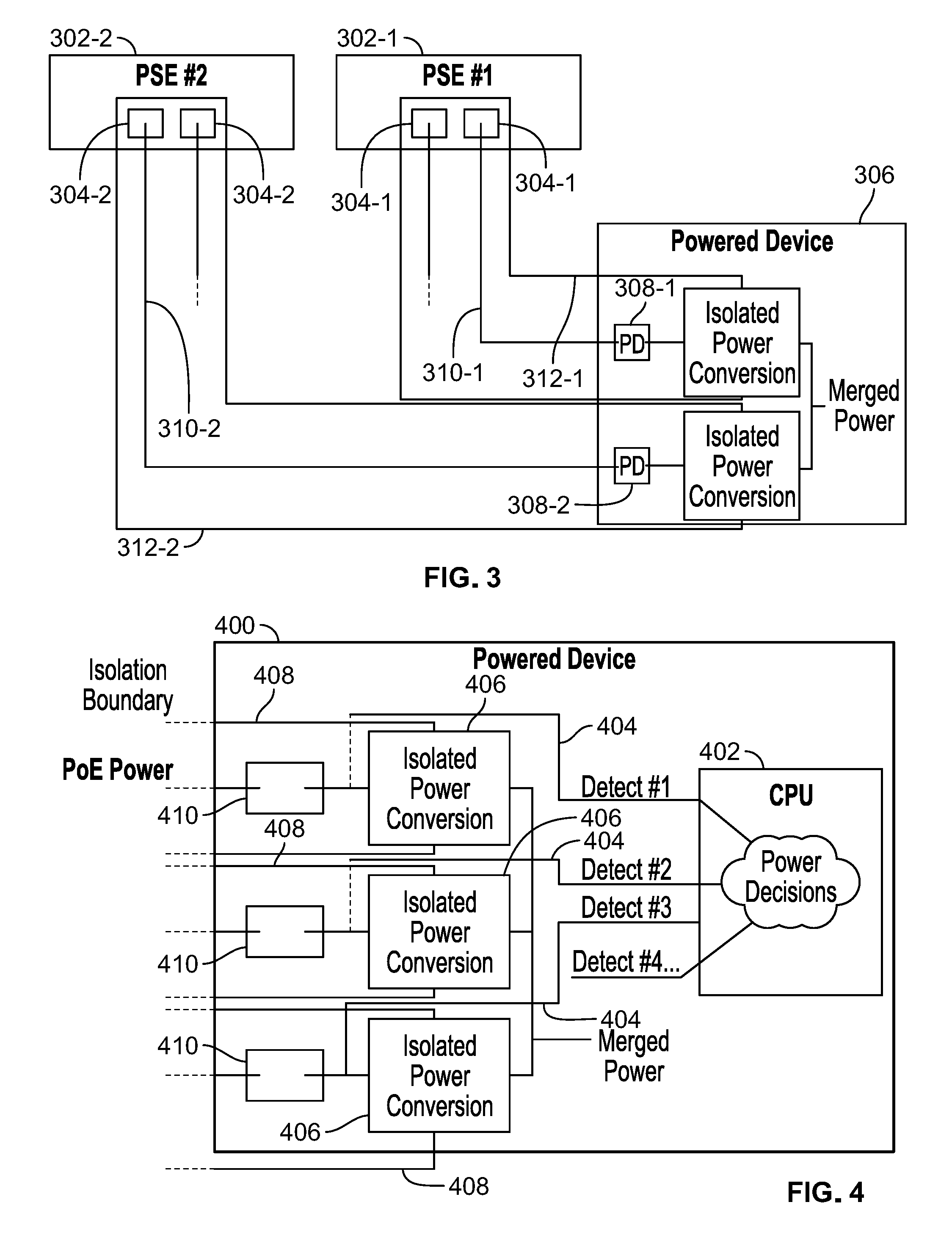
[0012] FIG. 3 depicts an illustrative system implementing an isolation boundary for powering a single PD using multiple PSEs, in accordance with some embodiments of the disclosure;
[0013] FIG. 4 depicts an illustrative powered device with a control circuitry for, among other things, making power decisions, in accordance with some embodiments of the disclosure;
[0014] FIG. 5 depicts an illustrative flowchart of a process for using a PoE system to power a powered device by drawing power from multiple PSEs, in accordance with some embodiments of the disclosure; and
[0015] FIG. 6 depicts an illustrative flowchart of a process for determining whether to operate a powered device in a first power mode or a second power mode based on power available from multiple PSEs that are coupled to a powered device by way of PoE links, in accordance with some embodiments of the disclosure.
DETAILED DESCRIPTION
[0016] In some aspects of the disclosure, systems, methods, and apparatuses are described herein for enabling a PD to draw power from multiple PSEs. In order for a PD to draw power from multiple PSEs, an isolation boundary must exist between PoE input voltages and external connections. As used herein, the term "isolation boundary" is a boundary that isolates a threshold amount of voltage between PoE input voltages and any external connections, for the purpose of preventing interference with interactions of input ports and any points of non-isolation. Examples of non-isolation include connecting an input voltage rail (power or return) to frame ground, connecting power or return of redundant ports to one another, or connecting one of the input voltage rails to an output voltage (or ground). While any level of isolation is within the scope of this disclosure, as described by the IEEE 802.3af, 802.3at, and 802.3bt standards, an isolation boundary should have at least 1500V between the PoE input voltages and any external connections. An isolation boundary may be implemented using any form of insulator.
[0017] FIG. 1 depicts an illustrative system implementing an isolation boundary for powering multiple PDs using multiple PSE interfaces from a same PSE, in accordance with some embodiments of the disclosure. PSE 102 uses power outputs 104 to transmit power over Ethernet links 110 to input ports 108 of powered devices 106. Isolation boundary 112 isolates all elements of FIG. 1 from any external connections.
[0018] FIG. 2 depicts an illustrative system implementing an isolation boundary for powering a single PD using multiple PSE interfaces from a same PSE, in accordance with some embodiments of the disclosure. Similar to FIG. 1, PSE 202 uses power outputs 204 to transmit power over Ethernet links 210 to input ports 108 of powered device 106. As depicted in FIG. 2, isolated power conversion occurs in the powered device before the isolation boundary. However, in many cases, it is only acceptable to merge power within isolation boundary 212 if power comes from a same PSE 202. If power comes from two separate sources, isolation must be maintained between the separate sources, and thus the configuration of FIG. 2 would not work if power outputs 204 were implemented in two different PSEs.
[0019] FIG. 3 depicts an illustrative system implementing an isolation boundary for powering a single PD using multiple PSEs, in accordance with some embodiments of the disclosure. In FIG. 3, two separate power sources, 302-1 and 302-2, respectfully power powered device 306 using power outputs 304-1 and 304-2. Power is transmitted from power outputs 304-1 and 304-2 to input ports 308 of powered device 306 by way of Ethernet links 310-1 and 310-2, respectively. Critically, two separate isolation boundaries 312-1 and 312-2 isolate the power conversion for power provided from PSE 304-1 and PSE 304-2, respectively. This is because, when power comes from two separate sources, isolation must be maintained between them. If isolation is not maintained (e.g., due to a short circuit occurring, a cabling error, or the like), then failure can occur. Moreover, if PSEs 304-1 and 304-2 output voltages at different voltage levels, then system failure could occur if isolation boundaries 312-1 and/or 312-2 were not present.
[0020] FIG. 4 depicts an illustrative powered device with control circuitry for, among other things, making power decisions, in accordance with some embodiments of the disclosure. In FIG. 4, powered device 400 includes control circuitry 402. Control circuitry 402 is configured to detect, using detection circuitry 404, PoE power source capacity from PSEs (not depicted) that are operably coupled to powered device 400 by way of interfaces 410. Interfaces 410 are coupled to isolated power converters 406. Each interface 410 and isolated power converter 406 is isolated from each other interface 410 and isolated power converter 406 by way of isolation boundaries 408.
[0021] As explained above, control circuitry 402 may use detection circuitry 404 to detect all potential input power available to powered device 400 from PSEs that are coupled to powered device 400. Control circuitry 402 may then command interfaces 410 to draw power at different levels from the PSEs to which interfaces 410 are connected in order to optimize performance.
[0022] To this end, control circuitry 402 may detect individual PoE power source capacity from each PSE that is coupled to an interface 410. Additionally, powered device 400 may determine a number of sources that are coupled to interface 410. Each isolated power circuit (e.g., circuits within isolation boundaries 408) may then share power. Control circuitry 402 may cause the power sharing to be performed in a manner that load balances power draw from each PSE and otherwise regulates power to powered device 400. As an example of load balancing, if a PD requires 100 W, and four PSEs are connected to the PD with a maximum output of 25 W, 50 W, 75 W, and 100 W, all four PSEs may provide an equal amount of power--25 W--to the PD. As another example of load balancing, power output may be determined based on a PSE's maximum power output. For example, if there are 3 PSEs powering a 100 W device, with a maximum respective power output of 25 W, 75 W, and 100 W, the control circuitry may perform load balancing by having each PSE provide half of its maximum power (e.g., 12.5 W, 37.5 W, and 50 W) to the PD. Any form of load balancing may be commanded by the control circuitry. Power sharing may occur through any known sharing mechanism, such as droop sharing or active current sharing.
[0023] Control circuitry 402 may detect that a PSE connected to an interface 410 that powered device 400 is drawing power from has stopped providing power (e.g., due to disconnect, failure, or PSE configuration). Control circuitry 402 may responsively take action to ensure powered device 400 continues to draw enough power by way of interfaces 410 to operate.
[0024] In some embodiments, control circuitry 402 may take such action by determining whether powered device 400 can draw sufficient power from remaining PSEs to which powered device 400 is connected. For example, if powered device 400 requires 90 W to be operational, and if powered device is connected to PSE 1 which has a maximum output of 50 W, PSE 2, which has a maximum output of 40 W, and PSE 3 which has a maximum output of 30 W, powered device 400 may be powered by drawing 30 W from each of PSE 1, PSE 2, and PSE 3. If PSE 3 were to fail, control circuitry 400, in response to detecting the failure, may continue to be fully operational by drawing 50 W from PSE 1, and 40V from PSE 2, thus resulting in powered device 400 drawing the requisite 90 W of power.
[0025] In some embodiments, control circuitry 402 may take action to ensure powered device 400 continues to draw enough power by way of interfaces 410 to operate by switching to a low power mode when a PSE failure is detected. Following from the example above, powered device 400 may require 90 W to operate in a high power mode, and may require 50 W to operate in a low power mode. Thus, if PSE 1 were to fail, powered device 400 may responsively switch to drawing 25 W from PSE 2 and from PSE 3, and may thus continue to operate in low power mode by switching the amount of power powered device 400 draws from the PSEs that powered device 400 is still connected to. Similarly, if PSE 1 were to be detected as being again operational, control circuitry 402 may cause powered device 400 to again draw power from PSE 1 and transition back to high power mode.
[0026] FIG. 5 depicts an illustrative flowchart of a process for using a PoE system to power a powered device by drawing power from multiple PSEs, in accordance with some embodiments of the disclosure. Process 500 begins at 502, where control circuitry (e.g., control circuitry 402) determines an amount of power necessary to operate a powered device (e.g., powered device 400) in a first power mode (e.g., a low-power mode). At 504, the control circuitry causes the powered device to draw, from a first power sourcing device (e.g., PSE 302-1), to a first port of the powered device (e.g., 308-1), over a first Ethernet link (e.g., 310-1), a first wattage.
[0027] At 506, the control circuitry causes the powered device to draw, from a second power sourcing device (e.g., PSE 302-2), to a second port of a powered device (e.g., 308-2), over a second Ethernet link (e.g., 310-2), a second wattage, wherein a sum of the first wattage and the second wattage equals the amount of power necessary to operate in the first power mode, wherein a first isolation boundary (e.g., 312-1) isolates the first power sourcing equipment (e.g., 302-1), the first Ethernet link (e.g., 310-1), and the first port (e.g., 308-1), and wherein a second isolation boundary (e.g., 312-2) isolates the second power sourcing equipment (e.g., 302-2), the second Ethernet link (e.g., 310-2), and the second port (e.g., 308-2).
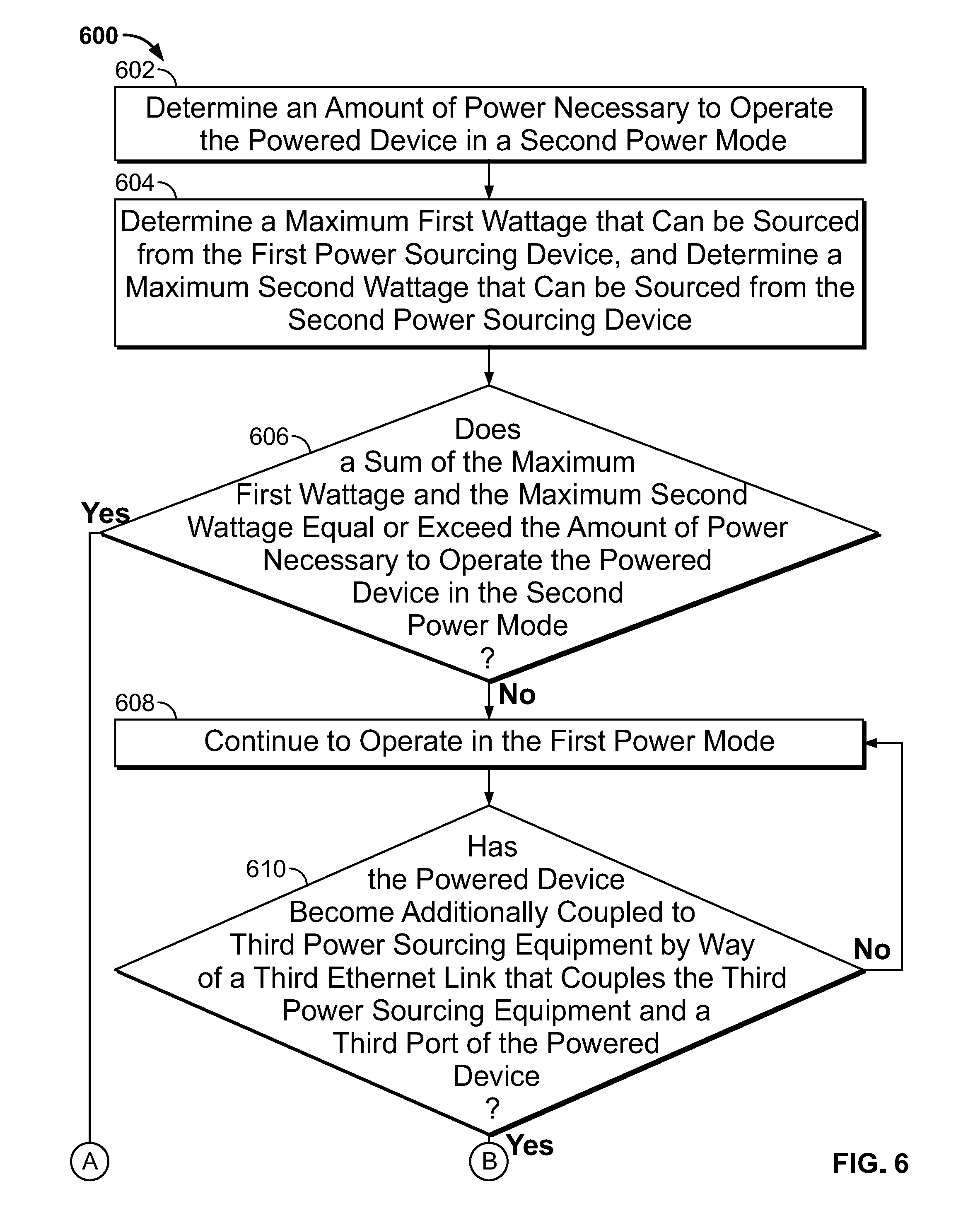
[0028] FIG. 6 depicts an illustrative flowchart of a process for determining whether to operate a powered device in a first power mode or a second power mode based on power available from multiple PSEs that are coupled to a powered device by way of PoE links, in accordance with some embodiments of the disclosure. Process 600 begins at 602, where control circuitry (e.g., control circuitry 402) determines an amount of power necessary to operate the powered device (e.g., powered device 400) in a second power mode (e.g., a high power mode). At 604, the control circuitry determines a maximum first wattage that can be sourced from the first power sourcing device (e.g., PSE 302-1), and determines a maximum second wattage that can be sourced from the second power sourcing device (e.g., PSE 302-2).
[0029] At 606, the control circuitry determines whether a sum of the maximum first wattage and the maximum second wattage equals or exceeds the amount of power necessary to operate the powered device in the second power mode. If the determination is in the negative, then process 600 continues to 608, where the control circuitry continues to operate the powered device in the first power mode (e.g., a low power mode). If the determination is in the affirmative, then process 600 continues to 620, where the control circuitry causes the powered device to draw, from, collectively, the first power sourcing device and the second power sourcing device, the amount of power necessary to operate the powered device in the second power mode, and at 622, the control circuitry transitions the powered device from the first power mode to the second power mode.
[0030] Following from 608, where the powered device is caused to operate in the first power mode (e.g., a low power mode), process 600 continues to 610, where the control circuitry determines whether the powered device has become additionally coupled to third power sourcing equipment by way of a third Ethernet link that couples the third power sourcing equipment and a third port of the powered device. If the determination is in the negative, process 600 reverts to 608. If the determination is in the affirmative, process 600 continues to 612, where the control circuitry determines a maximum third wattage that can be sourced from the third power sourcing device.
[0031] At 614, the control circuitry determines whether the sum of the maximum first wattage, maximum second wattage, and maximum third wattage is less than the second amount of input wattage required to operate in the second power mode. If the determination is in the negative, process 600 goes to 616, where the control circuitry transitions the powered device from the first power mode to the second power mode (e.g., from a low power mode to a high power mode). If the determination is in the affirmative, process 600 continues to 618, where the control circuitry causes the powered device to continue to operate in the first power mode.
[0032] The foregoing describes systems, methods, and apparatuses for configuring and implementing an environment where a PD is powered by way of multiple PSEs. The above-described embodiments of the present disclosure are presented for the purposes of illustration and not of limitation. Furthermore, the present disclosure is not limited to a particular implementation. For example, one or more steps of the methods described above may be performed in a different order (or concurrently) and still achieve desirable results. In addition, the disclosure may be implemented in hardware, such as on an application-specific integrated circuit (ASIC) or on a field-programmable gate array (FPGA). The disclosure may also be implemented in software by, for example, encoding transitory or non-transitory instructions for performing the process discussed above in one or more transitory or non-transitory computer-readable media.
[0033] While some portions of this disclosure may make reference to "convention," or "related art," any such reference is merely for the purpose of providing context to the invention(s) of the instant disclosure, and does not form any admission, express or implied, as to what constitutes the state of the prior art. As referred herein, the term "in response to" refers to initiated as a result of. For example, a first action being performed in response to a second action may include interstitial steps between the first action and the second action. As referred herein, the term "directly in response to" refers to caused by. For example, a first action being performed directly in response to a second action may not include interstitial steps between the first action and the second action.
[0034] While the term "wattage" is used throughout this disclosure, and examples of implementation are given in terms of "watts," this is merely exemplary; any unit of power output may interchangeably be used in place of these terms. Similarly, while the term "voltage" is used throughout this disclosure, and examples of implementation are given in terms of "volts," this is merely exemplary; any unit of electrical potential energy may interchangeably be used in place of these terms.
[0035] The figures referred to herein are merely exemplary, and are not limiting examples of the disclosure. For example, while FIG. 3 depicts a PD being coupled to two PSEs using two ports, any number of ports may be used to couple a PD to any number of PSEs. Similarly, in FIG. 4, any number of interfaces 410 may be used to connect a PD to any number of PSEs.
* * * * *
D00000
D00001
D00002
D00003
D00004
D00005
XML
uspto.report is an independent third-party trademark research tool that is not affiliated, endorsed, or sponsored by the United States Patent and Trademark Office (USPTO) or any other governmental organization. The information provided by uspto.report is based on publicly available data at the time of writing and is intended for informational purposes only.
While we strive to provide accurate and up-to-date information, we do not guarantee the accuracy, completeness, reliability, or suitability of the information displayed on this site. The use of this site is at your own risk. Any reliance you place on such information is therefore strictly at your own risk.
All official trademark data, including owner information, should be verified by visiting the official USPTO website at www.uspto.gov. This site is not intended to replace professional legal advice and should not be used as a substitute for consulting with a legal professional who is knowledgeable about trademark law.