Thermosyphon-type Heat Dissipation Device
CHEN; CHIEN-AN ; et al.
U.S. patent application number 16/217437 was filed with the patent office on 2019-06-13 for thermosyphon-type heat dissipation device. The applicant listed for this patent is AURAS Technology Co., Ltd.. Invention is credited to CHIEN-AN CHEN, CHIEN-YU CHEN, MU-SHU FAN, TIAN-LI YE.
| Application Number | 20190178583 16/217437 |
| Document ID | / |
| Family ID | 66735287 |
| Filed Date | 2019-06-13 |


| United States Patent Application | 20190178583 |
| Kind Code | A1 |
| CHEN; CHIEN-AN ; et al. | June 13, 2019 |
THERMOSYPHON-TYPE HEAT DISSIPATION DEVICE
Abstract
A thermosyphon-type heat dissipation device includes a heat-absorbing head and a radiator. The heat-absorbing head includes a first outlet, a first inlet, an evaporation chamber and a liquid return chamber. The first outlet is connected with the evaporation chamber. The first inlet is connected with the liquid return chamber. The evaporation chamber and the liquid return chamber are in communication with each other through a gap. An inner space of the evaporation chamber is larger than an inner space of the liquid return chamber. The radiator includes a second inlet and a second outlet. The second inlet is in communication with the first outlet. The second outlet is in communication with the first inlet.
| Inventors: | CHEN; CHIEN-AN; (New Taipei City, TW) ; FAN; MU-SHU; (New Taipei City, TW) ; CHEN; CHIEN-YU; (New Taipei City, TW) ; YE; TIAN-LI; (New Taipei City, TW) | ||||||||||
| Applicant: |
|
||||||||||
|---|---|---|---|---|---|---|---|---|---|---|---|
| Family ID: | 66735287 | ||||||||||
| Appl. No.: | 16/217437 | ||||||||||
| Filed: | December 12, 2018 |
Related U.S. Patent Documents
| Application Number | Filing Date | Patent Number | ||
|---|---|---|---|---|
| 62598130 | Dec 13, 2017 | |||
| Current U.S. Class: | 1/1 |
| Current CPC Class: | F28D 1/0226 20130101; H01L 23/427 20130101; F28D 2021/0029 20130101; F28D 21/00 20130101; F28D 15/0266 20130101; F28D 2021/0066 20130101; F28D 2001/0286 20130101; F28D 15/0275 20130101; F28D 2021/0031 20130101 |
| International Class: | F28D 15/02 20060101 F28D015/02; F28D 1/02 20060101 F28D001/02; F28D 21/00 20060101 F28D021/00 |
Foreign Application Data
| Date | Code | Application Number |
|---|---|---|
| Dec 12, 2018 | TW | 107144822 |
Claims
1. A thermosyphon-type heat dissipation device, comprising: a heat-absorbing head comprising a first outlet, a first inlet, an evaporation chamber and a liquid return chamber, wherein the first outlet is connected with the evaporation chamber, the first inlet is connected with the liquid return chamber, the evaporation chamber and the liquid return chamber are in communication with each other through a gap, and an inner space of the evaporation chamber is larger than an inner space of the liquid return chamber; and a radiator comprising a second inlet and a second outlet, wherein the second inlet is in communication with the first outlet, and the second outlet is in communication with the first inlet.
2. The thermosyphon-type heat dissipation device according to claim 1, further comprising a pipe, wherein the pipe is connected with the first outlet and the second inlet, and the pipe is connected with the second outlet and the first inlet.
3. The thermosyphon-type heat dissipation device according to claim 2, wherein the pipe is a hard conduit or a flexible tube.
4. The thermosyphon-type heat dissipation device according to claim 2, wherein the pipe is made of a plastic material or a non-plastic material.
5. The thermosyphon-type heat dissipation device according to claim 1, further comprising a pump, wherein the pump is connected between the second outlet and the first inlet.
6. The thermosyphon-type heat dissipation device according to claim 1, wherein the heat-absorbing head comprises a top cover and a base, and the liquid return chamber and the evaporation chamber are defined by the top cover and the base collaboratively, wherein a bottom surface of the base is in thermal contact with a heat source, and the shortest distance between the gap and the bottom surface of the base is smaller than the shortest distance between the first outlet and the bottom surface of the base.
7. The thermosyphon-type heat dissipation device according to claim 6, wherein the top cover has a guiding slant, wherein when a working medium is heated, the working medium is guided to the first outlet by the guiding slant.
8. The thermosyphon-type heat dissipation device according to claim 1, wherein the radiator comprises a first compartment, a second compartment, a third compartment and a fourth compartment, wherein the first compartment is in communication with the second inlet, the fourth compartment is in communication with the second outlet, the first compartment and the second compartment are in communication with each other through a first fluid channel group, the second compartment and the third compartment are in communication with each other through a second fluid channel group, and the third compartment and the fourth compartment are in communication with each other through a third fluid channel group, wherein a flowing direction of the first fluid channel group is reverse to a flowing direction of the second fluid channel group, and the flowing direction of the second fluid channel group is reverse to a flowing direction of the third fluid channel group.
9. The thermosyphon-type heat dissipation device according to claim 8, wherein the first compartment and the third compartment are located at a first side of the radiator, the first compartment is located over the third compartment, the second compartment and the fourth compartment are located at a second side of the radiator, and the second compartment is located over the fourth compartment.
10. The thermosyphon-type heat dissipation device according to claim 1, wherein the radiator comprises plural compartments and plural fluid channels in communication with the plural compartments, wherein one of the plural compartments is in communication with the second outlet and has the smallest inner space among the plural compartments.
11. The thermosyphon-type heat dissipation device according to claim 1, wherein the radiator comprises plural compartments and plural fluid channels in communication with the plural compartments, wherein a first compartment of the plural compartments is in communication with the second outlet, and the first compartment is in communication with a second compartment of the plural compartments through a first fluid channel group, wherein an inner space of the second compartment is larger than an inner space of the second compartment.
12. The thermosyphon-type heat dissipation device according to claim 1, wherein when the thermosyphon-type heat dissipation device is installed in an electronic device, the second inlet is at a level higher than the second outlet.
13. The thermosyphon-type heat dissipation device according to claim 1, wherein when the thermosyphon-type heat dissipation device is installed in an electronic device, the first outlet is at a level higher than the first inlet.
14. The thermosyphon-type heat dissipation device according to claim 1, wherein a working medium is filled in the thermosyphon-type heat dissipation device, and the working medium is an engineered fluid with low boiling point or water, wherein during a process of heating or cooling the working medium, the working medium undergoes a two-phase liquid-gas or gas-liquid transformation.
15. A thermosyphon-type heat dissipation device, comprising: a heat-absorbing head comprising a first outlet, a first inlet, a top cover, a base, an evaporation chamber, a liquid return chamber and a gap, wherein the liquid return chamber and the evaporation chamber are defined by the top cover and the base collaboratively, the first outlet is connected with the evaporation chamber, the first inlet is connected with the liquid return chamber, the evaporation chamber and the liquid return chamber are in communication with each other through the gap, and a working medium is filled in the heat-absorbing head, wherein when the working medium in the evaporation chamber is heated, the working medium is transformed from a liquid state into a gaseous state and the gaseous working medium is outputted from the first outlet, wherein the working medium in the liquid return chamber is in the liquid state and transferred to the evaporation chamber through a capillary action of the gap; and a radiator comprising a second inlet and a second outlet, wherein the second inlet is in communication with the first outlet, the second outlet is in communication with the first inlet, and the working medium is transformed from the gaseous state into the liquid state by the radiator.
16. The thermosyphon-type heat dissipation device according to claim 15, further comprising a pipe, wherein the pipe is connected with the first outlet and the second inlet, and the pipe is connected with the second outlet and the first inlet.
17. The thermosyphon-type heat dissipation device according to claim 15, further comprising a pump, wherein the pump is connected between the second outlet and the first inlet.
18. The thermosyphon-type heat dissipation device according to claim 15, wherein a bottom surface of the base is in thermal contact with a heat source, and the shortest distance between the gap and the bottom surface of the base is smaller than the shortest distance between the first outlet and the bottom surface of the base.
19. The thermosyphon-type heat dissipation device according to claim 15, wherein the top cover has a guiding slant, wherein when the working medium is heated, the working medium is guided to the first outlet by the guiding slant.
20. The thermosyphon-type heat dissipation device according to claim 15, wherein the radiator comprises a first compartment, a second compartment, a third compartment and a fourth compartment, wherein the first compartment is in communication with the second inlet, the fourth compartment is in communication with the second outlet, the first compartment and the second compartment are in communication with each other through a first fluid channel group, the second compartment and the third compartment are in communication with each other through a second fluid channel group, and the third compartment and the fourth compartment are in communication with each other through a third fluid channel group, wherein a flowing direction of the first fluid channel group is reverse to a flowing direction of the second fluid channel group, and the flowing direction of the second fluid channel group is reverse to a flowing direction of the third fluid channel group.
21. The thermosyphon-type heat dissipation device according to claim 20, wherein the first compartment and the third compartment are located at a first side of the radiator, the first compartment is located over the third compartment, the second compartment and the fourth compartment are located at a second side of the radiator, and the second compartment is located over the fourth compartment.
22. The thermosyphon-type heat dissipation device according to claim 15, wherein the radiator comprises plural compartments and plural fluid channels in communication with the plural compartments, wherein one of the plural compartments is in communication with the second outlet and has the smallest inner space among the plural compartments.
23. The thermosyphon-type heat dissipation device according to claim 15, wherein the radiator comprises plural compartments and plural fluid channels in communication with the plural compartments, wherein a first compartment of the plural compartments is in communication with the second outlet, and the first compartment is in communication with a second compartment of the plural compartments through a first fluid channel group, wherein an inner space of the second compartment is larger than an inner space of the second compartment.
24. The thermosyphon-type heat dissipation device according to claim 15, wherein when the thermosyphon-type heat dissipation device is installed in an electronic device, the second inlet is at a level higher than the second outlet.
25. The thermosyphon-type heat dissipation device according to claim 15, wherein when the thermosyphon-type heat dissipation device is installed in an electronic device, the first outlet is at a level higher than the first inlet.
26. The thermosyphon-type heat dissipation device according to claim 15, wherein the working medium is an engineered fluid with low boiling point or water, wherein during a process of heating or cooling the working medium, the working medium undergoes a two-phase liquid-gas or gas-liquid transformation.
27. A heat-absorbing head, comprising: an evaporation chamber; a liquid return chamber; an outlet connected with the evaporation chamber; and an inlet connected with the liquid return chamber, wherein when the heat-absorbing head is in horizontal placement and attached on a heat source, the inlet is located at a lateral side of the heat-absorbing head, wherein when the heat-absorbing head is in vertical placement and attached on the heat source, the inlet is located at a lower position of the heat-absorbing head.
28. The heat-absorbing head according to claim 27, wherein the evaporation chamber and the liquid return chamber are in communication with each other through a gap, and the gap comprises plural slits.
Description
CROSS-REFERENCE TO RELATED APPLICATION
[0001] This application claims priority to U.S. Provisional Patent Application No. 62/598,130 filed Dec. 13, 2017, the contents of which are incorporated herein by reference.
FIELD OF THE INVENTION
[0002] The present invention relates to a thermosyphon-type heat dissipation device, and more particularly to a liquid cooling heat dissipation device that is operated according to a thermosyphon mechanism.
BACKGROUND OF THE INVENTION
[0003] A conventional water-cooling heat dissipation device comprises a heat-absorbing head, a radiator, a fan and a pump. These components are connected with each other through a piping system. A liquid working medium is filled in a circulation path. During operation of the water-cooling heat dissipation device, the heated working medium is transferred from the heat-absorbing head to the radiator. In addition, the working medium is cooled down by the fan and fins. Afterwards, the working medium is returned back to the heat-absorbing head by the pump.
[0004] In case that the water-cooling architecture is able to undergo the liquid-gas transformation like a thermosyphon-type heat dissipation device, more heat from the heat source can be removed. In other words, the conventional water-cooling heat dissipation device needs to be improved.
SUMMARY OF THE INVENTION
[0005] In accordance with an aspect of the present invention, there is provided a thermosyphon-type heat dissipation device. The thermosyphon-type heat dissipation device includes a heat-absorbing head and a radiator. The heat-absorbing head includes a first outlet, a first inlet, an evaporation chamber and a liquid return chamber. The first outlet is connected with the evaporation chamber. The first inlet is connected with the liquid return chamber. The evaporation chamber and the liquid return chamber are in communication with each other through a gap. An inner space of the evaporation chamber is larger than an inner space of the liquid return chamber. The radiator includes a second inlet and a second outlet. The second inlet is in communication with the first outlet. The second outlet is in communication with the first inlet.
[0006] In an embodiment, the thermosyphon-type heat dissipation device further includes a pipe. The pipe is connected with the first outlet and the second inlet, and the pipe is connected with the second outlet and the first inlet.
[0007] In an embodiment, the pipe is a hard conduit or a flexible tube.
[0008] In an embodiment, the pipe is made of a plastic material or a non-plastic material.
[0009] In an embodiment, the thermosyphon-type heat dissipation device further includes a pump. The pump is connected between the second outlet and the first inlet.
[0010] In an embodiment, the heat-absorbing head comprises a top cover and a base, and the liquid return chamber and the evaporation chamber are defined by the top cover and the base collaboratively. A bottom surface of the base is in thermal contact with a heat source. The shortest distance between the gap and the bottom surface of the base is smaller than the shortest distance between the first outlet and the bottom surface of the base.
[0011] In an embodiment, the top cover has a guiding slant. When a working medium is heated, the working medium is guided to the first outlet by the guiding slant.
[0012] In an embodiment, the radiator includes a first compartment, a second compartment, a third compartment and a fourth compartment. The first compartment is in communication with the second inlet. The fourth compartment is in communication with the second outlet. The first compartment and the second compartment are in communication with each other through a first fluid channel group. The second compartment and the third compartment are in communication with each other through a second fluid channel group. The third compartment and the fourth compartment are in communication with each other through a third fluid channel group. A flowing direction of the first fluid channel group is reverse to a flowing direction of the second fluid channel group. The flowing direction of the second fluid channel group is reverse to a flowing direction of the third fluid channel group.
[0013] In an embodiment, the first compartment and the third compartment are located at a first side of the radiator, the first compartment is located over the third compartment, the second compartment and the fourth compartment are located at a second side of the radiator, and the second compartment is located over the fourth compartment.
[0014] In an embodiment, the radiator includes plural compartments and plural fluid channels in communication with the plural compartments. Moreover, one of the plural compartments is in communication with the second outlet and has the smallest inner space among the plural compartments.
[0015] In an embodiment, the radiator includes plural compartments and plural fluid channels in communication with the plural compartments. A first compartment of the plural compartments is in communication with the second outlet. The first compartment is in communication with a second compartment of the plural compartments through a first fluid channel group. An inner space of the second compartment is larger than an inner space of the second compartment.
[0016] Preferably, when the thermosyphon-type heat dissipation device is installed in an electronic device, the second inlet is at a level higher than the second outlet.
[0017] Preferably, when the thermosyphon-type heat dissipation device is installed in an electronic device, the first outlet is at a level higher than the first inlet.
[0018] In an embodiment, a working medium is filled in the thermosyphon-type heat dissipation device, and the working medium is an engineered fluid with low boiling point or water. During a process of heating or cooling the working medium, the working medium undergoes a two-phase liquid-gas or gas-liquid transformation.
[0019] In accordance with another aspect of the present invention, there is provided a thermosyphon-type heat dissipation device. The thermosyphon-type heat dissipation device includes a heat-absorbing head and a radiator. The heat-absorbing head includes a first outlet, a first inlet, a top cover, a base, an evaporation chamber, a liquid return chamber and a gap. The liquid return chamber and the evaporation chamber are defined by the top cover and the base collaboratively. The first outlet is connected with the evaporation chamber. The first inlet is connected with the liquid return chamber. The evaporation chamber and the liquid return chamber are in communication with each other through the gap. A working medium is filled in the heat-absorbing head. When the working medium in the evaporation chamber is heated, the working medium is transformed from a liquid state into a gaseous state and the gaseous working medium is outputted from the first outlet. The working medium in the liquid return chamber is in the liquid state and transferred to the evaporation chamber through a capillary action of the gap. The radiator includes a second inlet and a second outlet. The second inlet is in communication with the first outlet, the second outlet is in communication with the first inlet. The working medium is transformed from the gaseous state into the liquid state by the radiator.
[0020] In an embodiment, the thermosyphon-type heat dissipation device further includes a pipe. The pipe is connected with the first outlet and the second inlet, and the pipe is connected with the second outlet and the first inlet.
[0021] In an embodiment, the thermosyphon-type heat dissipation device further includes a pump. The pump is connected between the second outlet and the first inlet.
[0022] In an embodiment, a bottom surface of the base is in thermal contact with a heat source, and the shortest distance between the gap and the bottom surface of the base is smaller than the shortest distance between the first outlet and the bottom surface of the base.
[0023] In an embodiment, the top cover has a guiding slant. When a working medium is heated, the working medium is guided to the first outlet by the guiding slant.
[0024] In an embodiment, the radiator includes a first compartment, a second compartment, a third compartment and a fourth compartment. The first compartment is in communication with the second inlet. The fourth compartment is in communication with the second outlet. The first compartment and the second compartment are in communication with each other through a first fluid channel group. The second compartment and the third compartment are in communication with each other through a second fluid channel group. The third compartment and the fourth compartment are in communication with each other through a third fluid channel group. A flowing direction of the first fluid channel group is reverse to a flowing direction of the second fluid channel group. The flowing direction of the second fluid channel group is reverse to a flowing direction of the third fluid channel group.
[0025] In an embodiment, the first compartment and the third compartment are located at a first side of the radiator, the first compartment is located over the third compartment, the second compartment and the fourth compartment are located at a second side of the radiator, and the second compartment is located over the fourth compartment.
[0026] In an embodiment, the radiator includes plural compartments and plural fluid channels in communication with the plural compartments. Moreover, one of the plural compartments is in communication with the second outlet and has the smallest inner space among the plural compartments.
[0027] In an embodiment, the radiator includes plural compartments and plural fluid channels in communication with the plural compartments. A first compartment of the plural compartments is in communication with the second outlet. The first compartment is in communication with a second compartment of the plural compartments through a first fluid channel group. An inner space of the second compartment is larger than an inner space of the second compartment.
[0028] Preferably, when the thermosyphon-type heat dissipation device is installed in an electronic device, the second inlet is at a level higher than the second outlet.
[0029] Preferably, when the thermosyphon-type heat dissipation device is installed in an electronic device, the first outlet is at a level higher than the first inlet.
[0030] In an embodiment, the working medium is an engineered fluid with low boiling point or water. During a process of heating or cooling the working medium, the working medium undergoes a two-phase liquid-gas or gas-liquid transformation.
[0031] In accordance with a further aspect of the present invention, there is provided a heat-absorbing head. The heat-absorbing head includes an inlet, an outlet, an evaporation chamber and a liquid return chamber. The outlet is connected with the evaporation chamber. The inlet is connected with the liquid return chamber. When the heat-absorbing head is in horizontal placement and attached on a heat source, the inlet is located at a lateral side of the heat-absorbing head. When the heat-absorbing head is in vertical placement and attached on the heat source, the inlet is located at a lower position of the heat-absorbing head.
[0032] In an embodiment, the evaporation chamber and the liquid return chamber are in communication with each other through a gap, and the gap includes plural slits.
[0033] The above objects and advantages of the present invention will become more readily apparent to those ordinarily skilled in the art after reviewing the following detailed description and accompanying drawings, in which:
BRIEF DESCRIPTION OF THE DRAWINGS
[0034] FIG. 1A is a schematic perspective view illustrating a thermosyphon-type heat dissipation device in a horizontal placement according to an embodiment of the present invention;
[0035] FIG. 1B is a schematic perspective view illustrating a thermosyphon-type heat dissipation device in a vertical placement according to an embodiment of the present invention;
[0036] FIG. 2 is a schematic cross-sectional view illustrating the heat-absorbing head of the thermosyphon-type heat dissipation device as shown in FIG. 1A and taken along the line 2-2;
[0037] FIG. 3 is a schematic cutaway view illustrating the heat-absorbing head of the thermosyphon-type heat dissipation device according to an embodiment of the present invention;
[0038] FIG. 4 is another schematic cutaway view illustrating the heat-absorbing head of the thermosyphon-type heat dissipation device according to an embodiment of the present invention;
[0039] FIG. 5 is a schematic cross-sectional view illustrating the radiator of the thermosyphon-type heat dissipation device as shown in FIG. 1A and taken along the line 5-5; and
[0040] FIG. 6 schematically the fluid channel design of another radiator used in the thermosyphon-type heat dissipation device of the present invention.
DETAILED DESCRIPTION OF THE PREFERRED EMBODIMENT
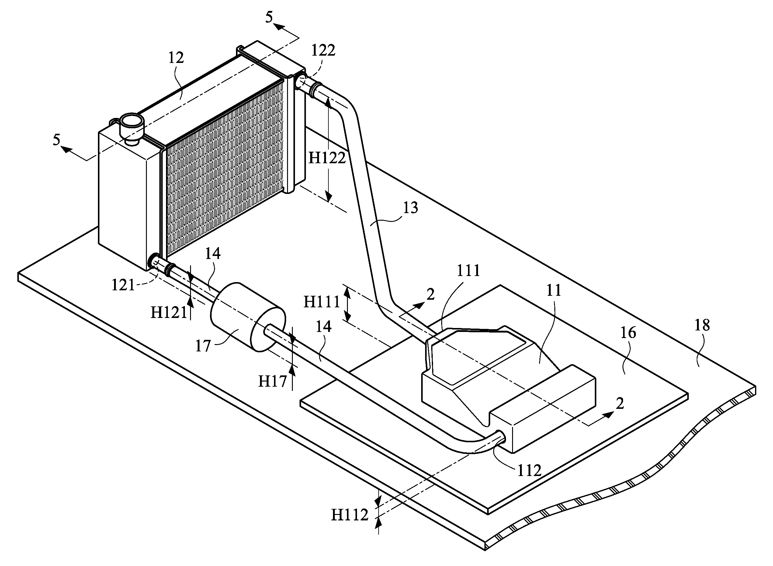
[0041] FIG. 1A is a schematic perspective view illustrating a thermosyphon-type heat dissipation device in a horizontal placement according to an embodiment of the present invention. FIG. 1B is a schematic perspective view illustrating a thermosyphon-type heat dissipation device in a vertical placement according to an embodiment of the present invention. FIG. 2 is a schematic cross-sectional view illustrating the heat-absorbing head of the thermosyphon-type heat dissipation device as shown in FIG. 1A and taken along the line 2-2. In an embodiment of the present invention, a thermosyphon-type heat dissipation device 1 is provided. The thermosyphon-type heat dissipation device 1 comprises a heat-absorbing head 11 and a radiator 12. The heat-absorbing head 11 comprises an outlet 111 and an inlet 112. The radiator 12 comprises an outlet 121 and an inlet 122. The outlet 111 of the heat-absorbing head 11 is in communication with the inlet 122 of the radiator 12. The outlet 121 of the radiator 12 is in communication with the inlet 112 of the heat-absorbing head 11. In some embodiments, the outlet 111 of the heat-absorbing head 11 and the inlet 122 of the radiator 12 are integrated with each other or directly coupled to each other. In some embodiments, the outlet 121 of the radiator 12 and the inlet 112 of the heat-absorbing head 11 are integrated with each other or directly coupled to each other. Moreover, the thermosyphon-type heat dissipation device 1 is equipped with a piping system to connect the heat-absorbing head 11 and the radiator 12. For example, the outlet 111 of the heat-absorbing head 11 and the inlet 122 of the radiator 12 are connected with each other through a pipe 13, and the outlet 121 of the radiator 12 and the inlet 112 of the heat-absorbing head 11 are connected with each other through a pipe 14. The pipes 13 and 14 are hard conduits (e.g., plastic hard conduits or flexible metallic conduit) or flexible tubes. According to the practical requirements or applications, the pipes 13 and 14 are made of a plastic material or a non-plastic material (e.g., a metallic material). The materials of the pipes 13 and 14 are not restricted.
[0042] In some other embodiments, the heat-absorbing head 11 has an additional outlet, and the radiator 12 has an additional inlet. The additional outlet of the heat-absorbing head 11 and the additional inlet of the radiator 12 are connected with each other through an additional pipe 13. Similarly, the heat-absorbing head 11 has an additional inlet, and the radiator 12 has an additional outlet. The additional inlet of the heat-absorbing head 11 and the additional outlet of the radiator 12 are connected with each other through an additional pipe 14.
[0043] Please refer to FIG. 1A, FIG. 1B and FIG. 2 again. The heat-absorbing head 11 of the thermosyphon-type heat dissipation device 1 may be horizontally or vertically attached on a heat source 15. For example, the heat source 15 is mounted on a PCB 16 within an electronic device 18. Consequently, the space utilization flexibility of the electronic device with the thermosyphon-type heat dissipation device 1 will be enhanced.
[0044] Please refer to FIG. 2. The heat-absorbing head 11 comprises a top cover 113 and a base 114. A bottom surface 1142 of the base 114 is in thermal contact with the heat source 15. For example, the base 114 is directly attached on the heat source 15, or an intermediate medium (a thermal grease, an adhesive or a soldering material) is clamped between the base 114 and the heat source 15. Moreover, a liquid return chamber 115 and an evaporation chamber 116 are defined by the top cover 113 and the base 114 of the heat-absorbing head 11 collaboratively. The inlet 112 is connected with the liquid return chamber 115. The outlet 111 is connected with the evaporation chamber 116. Preferably, the vacuum state of the heat-absorbing head 11 is previously created, and a working medium is filled in the heat-absorbing head 11. When the working medium in the evaporation chamber 116 absorbs heat, the working medium is transformed into the gaseous working medium. The gaseous working medium is ejected toward the outlet 111. There is a gap 117 between the evaporation chamber 116 and the liquid return chamber 115. The evaporation chamber 116 and the liquid return chamber 115 are in communication with each other through the gap 117. Due to the gap 117, the gaseous working medium in the evaporation chamber 116 is not returned back to the liquid return chamber 115. Moreover, because of the capillary action of the gap 117, the working medium in the liquid return chamber 115 can be continuously moved (or transferred) to the evaporation chamber 116. In the heat-absorbing head 11, the inner space of the evaporation chamber 116 is larger than the inner space of the liquid return chamber 115. Consequently, the possibility of returning the gaseous working medium in the evaporation chamber 116 back to the liquid return chamber 115 will be largely reduced.
[0045] In this embodiment, the gap 117 is formed in a stopping wall 1131 that is extended downwardly from the top cover 113. Preferably, the gap 117 runs through the stopping wall 1131. The position or the structure of the gap 117 is not restricted. In another embodiment, the gap 117 is formed in a stopping wall that is extended upwardly from the base 114. Alternatively, a portion of the top cover 113 and a portion of the base 114 at the junction region are not connected with each other or partially connected with each other to define the gap 117. That is, the way of defining the gap 117 is not restricted. Preferably, the installation position of the gap is specially designed. For example, the shortest distance D117 between the gap 17 and the bottom surface 1142 of the base 114 is smaller than the shortest distance D111 between the outlet 111 and the bottom surface 1142 of the base 114. Consequently, after the working medium is heated and evaporated, the working medium is moved toward the outlet 111 at the higher position because of the structural and pressure relationships. That is, the gaseous working medium is not moved toward the gap 117, which is located at the lower position and full of the liquid working medium.
[0046] Please refer to the cross-sectional view of FIG. 2 and the cutaway view of the heat-absorbing head 11 of FIG. 3. The heat-absorbing head 11 further comprises a boiling enhancement structure 1141. The boiling enhancement structure 1141 is formed on the base 114 for facilitating boiling the working medium. For example, the boiling enhancement structure 1141 comprises plural skived fins that are closely and densely arranged, or the boiling enhancement structure 1141 is another three-dimensional structure with a large surface area. When the bottom surface 1142 of the base 114 is in contact with the heat source 15, the boiling enhancement structure 1141 absorbs the heat from the heat source 15 at a faster rate. Consequently, the working medium is vaporized into the gaseous state more quickly. Moreover, since the structure of the evaporation chamber 116 is specially designed, the gaseous working medium is ejected toward the outlet 111
[0047] During the operation of the thermosyphon-type heat dissipation device 1, the working medium is filled in the thermosyphon-type heat dissipation device 1. In accordance with the present invention, the working medium is water or an engineered fluid with low boiling point. For example, the working medium is 3M Fluorinert FC-72 (boiling point is 56.degree. C.), 3M Novec Fluids 7000 (boiling point is 34.degree. C.) or 3M Novec Fluids 7100 (boiling point is 61.degree. C.). The example of the working medium is not restricted as long as the working medium flowing through the boiling enhancement structure 1141 is transformed into the gaseous state. Moreover, during the expanding and pressuring process, a great deal of heat is removed.
[0048] FIG. 3 is a schematic cutaway view illustrating the heat-absorbing head of the thermosyphon-type heat dissipation device according to an embodiment of the present invention. The design of the evaporation chamber 116 of the heat-absorbing head 11 can be seen from FIG. 1A, FIG. 2 and FIG. 3. As shown in these drawings, the evaporation chamber 116 is gradually widened in the direction from the liquid return chamber 115 (or the gap 117) to the outlet 111. As shown in the cross-sectional view of the heat-absorbing head 11 of FIG. 2, an inner surface of the top cover 113 has a guiding slant 1132. The guiding slant 1132 is located over the base 114 (or especially over the boiling enhancement structure 1141). Due to the guiding slant 1132, the gaseous working medium (or the heated mixture of the gaseous working medium and the liquid working medium) is guided in the direction A toward the outlet 111 of the heat-absorbing head 11.
[0049] Please refer to FIG. 1A and FIG. 1B. The thermosyphon-type heat dissipation device 1 is specially designed to allow the working medium to be stably transferred in one direction. For example, the height H122 of the inlet 122 of the radiator 12 is higher than the height H111 of the outlet 111 of the heat-absorbing head 11, and the height H122 of the inlet 122 of the radiator 12 is higher than the height H121 of the outlet 121 of the radiator 12. Consequently, during the operation of the thermosyphon-type heat dissipation device 1, the gaseous working medium is vaporized upwardly and fed into the inlet 122 of the radiator 12. After the gaseous working medium is transferred through the radiator 12, the gaseous working medium is transformed into the liquid state through condensation. The working medium flows to the outlet 121 of the radiator 12 along the gravity direction. Then, the working medium is returned to the liquid return chamber 115 of the heat-absorbing head 11 through the pipe 14. Consequently, the self-circulation efficacy is achieved.
[0050] For allowing the working medium to be smoothly transferred from the heat-absorbing head 11 to the radiator 12 or returned from the radiator 12 to the heat-absorbing head 11, the thermosyphon-type heat dissipation device 1 is additionally equipped with a pump. In an embodiment, the pump is connected between the outlet 121 of the radiator 12 and the inlet 112 of the heat-absorbing head 11. As shown in FIG. 1A, the pipe 14 is additionally connected with a pump 17. After the working medium is cooled down, the working medium can be smoothly moved from the radiator 12 to the heat-absorbing head 11 by the pump 17. Consequently, the backflow problem is avoided. In another embodiment, the pump is connected between the outlet 111 of the heat-absorbing head 11 and the inlet 122 of the radiator 12. For example, the pipe 13 is additionally connected with a pump (not shown). Due to the pump, the working medium can be smoothly moved from the heat-absorbing head 11 to the radiator 12. As mentioned above, the working medium used in the present invention is able to undergo the two phase transformation. Consequently, the selection of the pump is important. Preferably, the pump is capable of withstanding the cavitation effect, the formation of vapor cavities or the formation of the bubbles. Moreover, the number of the pump is not restricted. For example, plural pumps 17 are connected with the pipe 13 or the pipe 14 in series. In case that the thermosyphon-type heat dissipation device 1 comprises plural pipes 13 or 14, plural pumps 17 are connected with the pipes in parallel. That is, the arrangement of the pumps is not restricted.
[0051] Please refer to FIG. 1A and FIG. 1B again. As mentioned above, the heat-absorbing head 11 of the thermosyphon-type heat dissipation device 1 may be in the horizontal placement or the vertical placement. In case that the heat-absorbing head 11 is horizontally placed (see FIG. 1A), the inlet 112 of the heat-absorbing head 11 is located at a lateral side of the heat-absorbing head 11. In case that the heat-absorbing head 11 is vertically placed and attached on the heat source (see FIG. 1B), the inlet 112 of the heat-absorbing head 11 is located at a lower position of the heat-absorbing head 11. Under this circumstance, the height H111 of the outlet 111 of the heat-absorbing head 11 is higher than the height H112 of the inlet 112 of the heat-absorbing head 11. In addition, the height H112 of the inlet 112 of the heat-absorbing head 11 is lower than the height H121 of the outlet 121 of the radiator 12 or lower than the height H17 of the pump 17. In this context, the heights of the outlets, the inlets and the pump indicate the vertical distances from the same horizontal plane (e.g., a bottom plate or a casing of the electronic device). In case that the thermosyphon-type heat dissipation device 1 is equipped with the pump 17, the influence of the gravity force on the thermosyphon-type heat dissipation device 1 will be reduced. Under this circumstance, the heights of the outlets, the inlets and the pump are not restricted.
[0052] FIG. 4 is another schematic cutaway view illustrating the heat-absorbing head 11 of the thermosyphon-type heat dissipation device 1 according to an embodiment of the present invention. In this cutaway view, the liquid return chamber 115 and the gap 117 are shown. After the liquid working medium is returned back to the heat-absorbing head 11 through the pipe 14, the liquid working medium is not directly transferred to the evaporation chamber 116 of the heat-absorbing head 11. That is, the liquid working medium is stored in the liquid return chamber 115 of the heat-absorbing head 11 and then transferred to the evaporation chamber 116 through the capillary action. In an embodiment, the gap 117 is composed of at least one slit or opening. In the embodiment of FIG. 4, the gap 117 is composed of plural slits. The distribution range of the plural slits is substantially equal to width of the liquid return chamber 115 or contacted with both ends of the liquid return chamber 115. Consequently, even if the heat-absorbing head 11 is in the vertical placement (see FIG. 1B), the working medium can be transferred to the evaporation chamber 116 through a portion of the gap 117.
[0053] FIG. 5 schematically the fluid channel design of the radiator 12 used in the thermosyphon-type heat dissipation device 1 of this embodiment. As shown in this cross-sectional view of FIG. 5, the inner portion of the radiator 12 comprises a first compartment 123A, a second compartment 123B, a third compartment 123C, a fourth compartment 123D, three fluid channel groups and plural fins 125. The fins 125 are arranged between the fluid channels. The first compartment 123A and the third compartment 123C are located at the same side with the inlet 122. The first compartment 123A is located over the third compartment 123C. A partition wall 126 is arranged between the first compartment 123A and the third compartment 123C. The second compartment 123B and the fourth compartment 123D are located at the same side with the outlet 121. The second compartment 123B is located over the fourth compartment 123D. Similarly, a partition wall 127 is arranged between the second compartment 123B and the fourth compartment 123D.
[0054] Please refer to FIG. 5 again. The first fluid channel group 124A is connected between the first compartment 123A and the second compartment 123B. Consequently, the first compartment 123A and the second compartment 123B are in communication with each other. After the gaseous working medium (or the mixture of the gaseous working medium and the liquid working medium) is fed into the first compartment 123A through the inlet 122 of the radiator 12, the gaseous working medium (or the mixture of the gaseous working medium and the liquid working medium) is split and transferred to the second compartment 123B through the first fluid channel group 124A. The second fluid channel group 124B is connected between the second compartment 123B and the third compartment 123C. Consequently, the second compartment 123B and the third compartment 123C are in communication with each other. The flowing direction of the working medium in the second fluid channel group 124B is reverse to the flowing direction of the working medium in the first fluid channel group 124A. After the working medium is collected in the second compartment 123B, the working medium is transferred to the third compartment 123C through the second fluid channel group 124B. The third fluid channel group 124C is connected between the third compartment 123C and the fourth compartment 123D. Consequently, the third compartment 123C and the fourth compartment 123D are in communication with each other. The flowing direction of the working medium in the third fluid channel group 124C is reverse to the flowing direction of the working medium in the second fluid channel group 124B. After the working medium is collected in the third compartment 123C, the working medium is transferred to the fourth compartment 123D through the third fluid channel group 124C. Due to the S-shaped fluid channels, the working medium is naturally moved from the higher level to the lower level along the gravity direction. Moreover, since the inner space of each compartment is larger than the diameter of each fluid channel, the working medium is continuously transferred in one direction without backflow. Finally, the working medium is outputted from the outlet 121 of the radiator 12.
[0055] While the working medium is moved in the radiator 12, the heat energy contained in the working medium is transmitted to the fins 125 through the fluid channels of the fluid channel groups 124A, 124B and 124C. With the cooperation of a fan (not shown) or an airflow generation device to remove the heat, the working medium is transformed from the gaseous state to the liquid state and the working medium is cooled down. Then, the working medium is returned back to the liquid return chamber 115 of the heat-absorbing head 11. Then, the next liquid-gas circulation process will be performed.
[0056] For facilitating the operation of the pump 17, the working medium has to be in the liquid state when the working medium is outputted from the outlet 121 of the radiator 12. In order to achieve this purpose, the inner space of the compartment 123D in communication with the outlet 121 of the radiator 12 is the smallest among the compartments. Alternatively, the inner space of the second last compartment 123C is larger than the inner space of the last compartment 123D. The diameter of the third fluid channel group 124C connected between the compartment 123C and the compartment 123D is much smaller than the compartments 123C and 123D. Consequently, after the working medium is transformed into the liquid state, the working medium is transferred to the compartment 123D and outputted from the outlet 121.
[0057] The fluid channels in the radiator 12 are not restricted to the S-shaped configuration of FIG. 5. It is noted that numerous modifications and alterations may be made while retaining the teachings of the invention. FIG. 6 schematically the fluid channel design of another radiator 12' used in the thermosyphon-type heat dissipation device of the present invention. The configuration of FIG. 6 is substantially the image configuration of FIG. 5. As shown in this cross-sectional view of FIG. 6, the inner portion of the radiator 12' comprises a first compartment 123A', a second compartment 123B', a third compartment 123C', a fourth compartment 123D', three fluid channel groups and plural fins 125'. The fins 125' are arranged between the fluid channels. The first compartment 123A' and the third compartment 123C' are located at the same side with the inlet 122'. The second compartment 123B' and the fourth compartment 123D' are located at the same side with the outlet 121'. A partition wall 126' is arranged between the first compartment 123A' and the third compartment 123C'. Similarly, a partition wall 127' is arranged between the second compartment 123B' and the fourth compartment 123D'. The first fluid channel group 124A' is connected between the first compartment 123A' and the second compartment 123B'. After the gaseous working medium (or the mixture of the gaseous working medium and the liquid working medium) is fed into the first compartment 123A' through the inlet 122' of the radiator 12', the gaseous working medium (or the mixture of the gaseous working medium and the liquid working medium) is split and transferred to the second compartment 123B' through the first fluid channel group 124A'. The second fluid channel group 124B' is connected between the second compartment 123B' and the third compartment 123C'. After the working medium is collected in the second compartment 123B', the working medium is transferred to the third compartment 123C' through the second fluid channel group 124B'. The third fluid channel group 124C' is connected between the third compartment 123C' and the fourth compartment 123D'. After the working medium is collected in the third compartment 123C', the working medium is transferred to the fourth compartment 123D' through the third fluid channel group 124C'. Due to the S-shaped fluid channels, the working medium is naturally moved from the higher level to the lower level along the gravity direction and finally outputted from the outlet 121' of the radiator 12'. While the working medium is moved in the radiator 12', the heat energy contained in the working medium is transmitted to the fins 125' through the fluid channel groups 124A', 124B' and 124C'. With the cooperation of a fan (not shown) or an airflow generation device to remove the heat, the working medium is transformed from the gaseous state to the liquid state and the working medium is cooled down.
[0058] The inner fluid channel configurations as shown in FIG. 5 and FIG. 6 are presented herein for purpose of illustration and description only. In some other embodiments, the fluid channels allow the working medium to be transferred from left to right, from right to left, from top to bottom, from upper left to lower right or from the upper right to the lower left. The number of the compartments is not restricted. That is, the thermosyphon-type heat dissipation device may have more (e.g., 5 or 6) compartments or less (e.g., 3) compartments. The fluid channel configuration is not restricted as long as the inlet 122 of the radiator 12 is at the level higher than the outlet 121 of the radiator 12.
[0059] In the thermosyphon-type heat dissipation device 1 of the present invention, the base 114 of the heat-absorbing head 11 is made of a metallic material with good thermal conductivity (e.g., silver, copper, gold, aluminum, iron or alloy of the above metallic materials) or a nonmetallic material with good thermal conductivity (e.g., graphite). The top cover 113 and the base 114 are made of the identical thermal conductive material or different thermal conductive materials.
[0060] While the invention has been described in terms of what is presently considered to be the most practical and preferred embodiments, it is to be understood that the invention needs not be limited to the disclosed embodiments. On the contrary, it is intended to cover various modifications and similar arrangements included within the spirit and scope of the appended claims which are to be accorded with the broadest interpretation so as to encompass all modifications and similar structures.
* * * * *
D00000
D00001
D00002
D00003
D00004
D00005
D00006
D00007
XML
uspto.report is an independent third-party trademark research tool that is not affiliated, endorsed, or sponsored by the United States Patent and Trademark Office (USPTO) or any other governmental organization. The information provided by uspto.report is based on publicly available data at the time of writing and is intended for informational purposes only.
While we strive to provide accurate and up-to-date information, we do not guarantee the accuracy, completeness, reliability, or suitability of the information displayed on this site. The use of this site is at your own risk. Any reliance you place on such information is therefore strictly at your own risk.
All official trademark data, including owner information, should be verified by visiting the official USPTO website at www.uspto.gov. This site is not intended to replace professional legal advice and should not be used as a substitute for consulting with a legal professional who is knowledgeable about trademark law.