Multiple Tube Bank Heat Exchange Unit With Manifold Assembly
Taras; Michael F. ; et al.
U.S. patent application number 16/275081 was filed with the patent office on 2019-06-13 for multiple tube bank heat exchange unit with manifold assembly. The applicant listed for this patent is Carrier Corporation. Invention is credited to Arindom Joardar, Bruce J. Poplawski, Tobias H. Sienel, Michael F. Taras, Mel Woldesemayat.
| Application Number | 20190178580 16/275081 |
| Document ID | / |
| Family ID | 49780349 |
| Filed Date | 2019-06-13 |


| United States Patent Application | 20190178580 |
| Kind Code | A1 |
| Taras; Michael F. ; et al. | June 13, 2019 |
MULTIPLE TUBE BANK HEAT EXCHANGE UNIT WITH MANIFOLD ASSEMBLY
Abstract
A multiple bank, flattened tube heat exchange unit includes a first tube bank including a plurality of flattened tube segments extending longitudinally in spaced parallel relationship between a first manifold and a second manifold and a second tube bank including a plurality of flattened tube segments extending longitudinally in spaced parallel relationship between a first manifold and a second manifold, the second tube bank disposed behind the first tube bank. The second manifold of the first tube bank and the second manifold of the second tube bank form a manifold assembly wherein an interior volume of the second manifold of the first tube bank and an interior volume of the second manifold of the second tube bank of the manifold assembly are internally connected in fluid communication.
| Inventors: | Taras; Michael F.; (Fayetteville, NY) ; Joardar; Arindom; (Jamesville, NY) ; Sienel; Tobias H.; (Baldwinsville, NY) ; Woldesemayat; Mel; (Liverpool, NY) ; Poplawski; Bruce J.; (Mattydale, NY) | ||||||||||
| Applicant: |
|
||||||||||
|---|---|---|---|---|---|---|---|---|---|---|---|
| Family ID: | 49780349 | ||||||||||
| Appl. No.: | 16/275081 | ||||||||||
| Filed: | February 13, 2019 |
Related U.S. Patent Documents
| Application Number | Filing Date | Patent Number | ||
|---|---|---|---|---|
| 14763557 | Jul 27, 2015 | 10247481 | ||
| PCT/US2013/071644 | Nov 25, 2013 | |||
| 16275081 | ||||
| 61757273 | Jan 28, 2013 | |||
| Current U.S. Class: | 1/1 |
| Current CPC Class: | F28D 1/0417 20130101; B23P 15/26 20130101; F28D 1/05391 20130101; F28D 1/05358 20130101; F28F 9/0214 20130101; F28D 1/0435 20130101 |
| International Class: | F28D 1/04 20060101 F28D001/04; F28D 1/053 20060101 F28D001/053; F28F 9/02 20060101 F28F009/02; B23P 15/26 20060101 B23P015/26 |
Claims
1. A method of forming an integral manifold assembly for a multiple bank heat exchanger, comprising: extruding a dual-barrel manifold having a first tubular barrel and a second tubular barrel in spaced parallel relationship and a central web member interconnecting the first and second tubular barrels; forming an opening in a wall of one of the first and second tubular barrels opposite the central web member; inserting a drill bit through said opening and drilling a hole transversely through the central web member to form a bore opening in fluid communication with an interior volume of the first tubular barrel and an interior volume of the second tubular barrel; and plugging said opening after withdrawing the drill bit.
Description
CROSS-REFERENCE TO RELATED APPLICATIONS
[0001] This application is a divisional of U.S. application Ser. No. 14/763,557 filed Jul. 27, 2015, which is a National Stage Application of PCT/US2013/071644, filed Nov. 25, 2013, which claims the benefit of U.S. Provisional Application No. 61/757,273 filed Jan. 28, 2013, all of which are incorporated herein by reference in their entirety.
BACKGROUND
[0002] This invention relates generally to heat exchangers and, more particularly, to multiple tube bank heat exchange unit incorporating a manifold assembly.
[0003] Heat exchangers have long been used as evaporators and condensers in heating, ventilation, air conditioning and refrigeration (HVACR) applications. Historically, these heat exchangers have been round tube and plate fin (RTPF) heat exchangers. However, all aluminum flattened tube serpentine fin heat exchangers are finding increasingly wider use in industry, including the HVACR industry, due to their compactness, thermal-hydraulic performance, structural rigidity, lower weight and reduced refrigerant charge, in comparison to conventional RTPF heat exchangers. Flattened tubes commonly used in HVACR applications typically have an interior subdivided into a plurality of parallel flow channels. Such flattened tubes are commonly referred to in the art as multi-channel tubes, mini-channel tubes or micro-channel tubes.
[0004] A typical flattened tube serpentine fin heat exchanger includes a first manifold, a second manifold, and a single tube bank formed of a plurality of longitudinally extending flattened heat exchange tubes disposed in spaced parallel relationship and extending between the first manifold and the second manifold. The first manifold, second manifold and tube bank assembly is commonly referred to in the heat exchanger art as a slab. Additionally, a plurality of fins are disposed between the neighboring pairs of heat exchange tubes for increasing heat transfer between a fluid, commonly air in HVACR applications, flowing over the outside surfaces of the flattened tubes and along the fin surfaces and a fluid, commonly refrigerant in HVACR applications, flowing inside the flattened tubes. Such single tube bank heat exchangers, also known as single slab heat exchangers, have a pure cross-flow configuration.
[0005] Double bank flattened tube and serpentine fin heat exchangers are also known in the art. Conventional double bank flattened tube and serpentine fin heat exchangers are typically formed of two conventional fin and tube slabs, one spaced behind the other, with fluid communication between the manifolds accomplished through external piping. However, to connect the two slabs in fluid flow communication in other than a parallel cross-flow arrangement requires complex external piping. For example, U.S. Pat. No. 6,964,296 B2 and U.S. Patent Application Publication 2009/0025914 A1 disclose embodiments of double bank, multichannel flattened tube heat exchanger.
BRIEF DESCRIPTION
[0006] In an aspect, a multiple bank, flattened tube heat exchange unit includes a first tube bank including a plurality of flattened tube segments extending longitudinally in spaced parallel relationship between a first manifold and a second manifold and a second tube bank including a plurality of flattened tube segments extending longitudinally in spaced parallel relationship between a first manifold and a second manifold, the second tube bank disposed behind the first tube bank. The second manifold of the first tube bank and the second manifold of the second tube bank form a manifold assembly wherein an interior volume of the second manifold of the first tube bank and an interior volume of the second manifold of the second tube bank of the manifold assembly are connected in fluid communication internally, that is not through external piping.
BRIEF DESCRIPTION OF THE DRAWINGS
[0007] For further understanding of the disclosure, reference will be made to the following detailed description which is to be read in connection with the accompanying drawing, where:
[0008] FIG. 1 is a diagrammatic illustration of an embodiment of a multiple tube bank, flattened tube finned heat exchange unit as disclosed herein;
[0009] FIG. 2 is a side elevation view, partly in section, illustrating an embodiment of a fin and a set of integral flattened tube segment assemblies of the heat exchange unit of FIG. 1;
[0010] FIG. 3 is a top plan view of an embodiment single pass, multiple pass counter crossflow embodiment of the heat exchange unit of FIG. 1;
[0011] FIG. 4 is a top plan view of an embodiment single pass, single pass counter crossflow embodiment of the heat exchange unit of FIG. 1;
[0012] FIG. 5 is a sectioned plan view of an embodiment of a manifold assembly of paired generally D-shaped tubular manifolds at the intermediate side of the heat exchanger unit of FIG. 1 connected in fluid communication through a block insert disposed therebetween;
[0013] FIG. 6 is a sectioned plan view of an embodiment of a manifold assembly of paired generally cylindrical tubular manifolds at the intermediate side of the heat exchanger unit of FIG. 1 connected in fluid communication through a block insert disposed therebetween;
[0014] FIG. 7 is a sectioned plan view of an embodiment of a manifold assembly of paired generally cylindrical tubular manifolds at the intermediate side of the heat exchanger unit of FIG. 1 connected in fluid communication through a plurality of individual tubular members extending therebetween;
[0015] FIG. 8 is a sectioned plan view of another embodiment of a manifold assembly of paired generally tubular manifolds at the intermediate side of the heat exchanger unit of FIG. 1 connected in fluid communication through a plurality of individual tubular members extending therebetween;
[0016] FIG. 9 is a sectioned plan view of another embodiment of a manifold assembly of a full tubular manifold and a partially open tubular manifold disposed in interfacing abutting relationship at the intermediate side of the heat exchanger unit of FIG. 1;
[0017] FIGS. 10A and 10B are sectioned plan views of alternate embodiments of a manifold assembly of paired partially open tubular manifolds joined in engaging relationship at the intermediate side of the heat exchanger unit of FIG. 1;
[0018] FIG. 11 is a sectioned plan view of another embodiment of a manifold assembly of paired partially open tubular manifolds joined in interfacing abutting relationship at the intermediate side of the heat exchanger unit of FIG. 1;
[0019] FIG. 12 is a sectioned plan view of an embodiment of a manifold assembly of paired partially open tubular manifolds interconnected in fluid communication through a flow passage through a single block insert disposed between the manifolds;
[0020] FIG. 13 is a sectioned plan view of an embodiment of a manifold assembly of paired partially open tubular manifolds interconnected in fluid communication through a flow passage formed by two block inserts;
[0021] FIG. 14 is a sectioned plan view of an embodiment of a manifold assembly of paired partially open tubular manifolds interconnected in fluid communication through a flow passage through a block insert disposed internally at the interface between the manifolds;
[0022] FIG. 15 is a perspective view of a cladded sheet from which an integral folded manifold assembly may be formed;
[0023] FIG. 16 is a sectioned plan view of an embodiment of a generally tubular integral folded manifold assembly formed of a single folded sheet;
[0024] FIG. 17 is a sectioned plan view of another embodiment of a generally tubular integral folded manifold assembly formed of a single folded sheet;
[0025] FIG. 18 is a sectioned plan view of another embodiment of a generally tubular integral folded manifold assembly formed of a single folded sheet;
[0026] FIG. 19 is a sectioned plan view of an embodiment of an extruded dual-barrel embodiment of an integral manifold assembly;
[0027] FIG. 20 is a sectioned plan view of an embodiment of a fabricated flat integral manifold assembly defining a single fluid chamber;
[0028] FIG. 21 is a sectioned plan view of an embodiment of a fabricated flat integral manifold assembly defining a pair of fluid chambers; and
[0029] FIGS. 22A-D are sectioned plan views of various exemplary embodiments of a fabricated flat integral assembly formed from a single folded sheet.
DETAILED DESCRIPTION
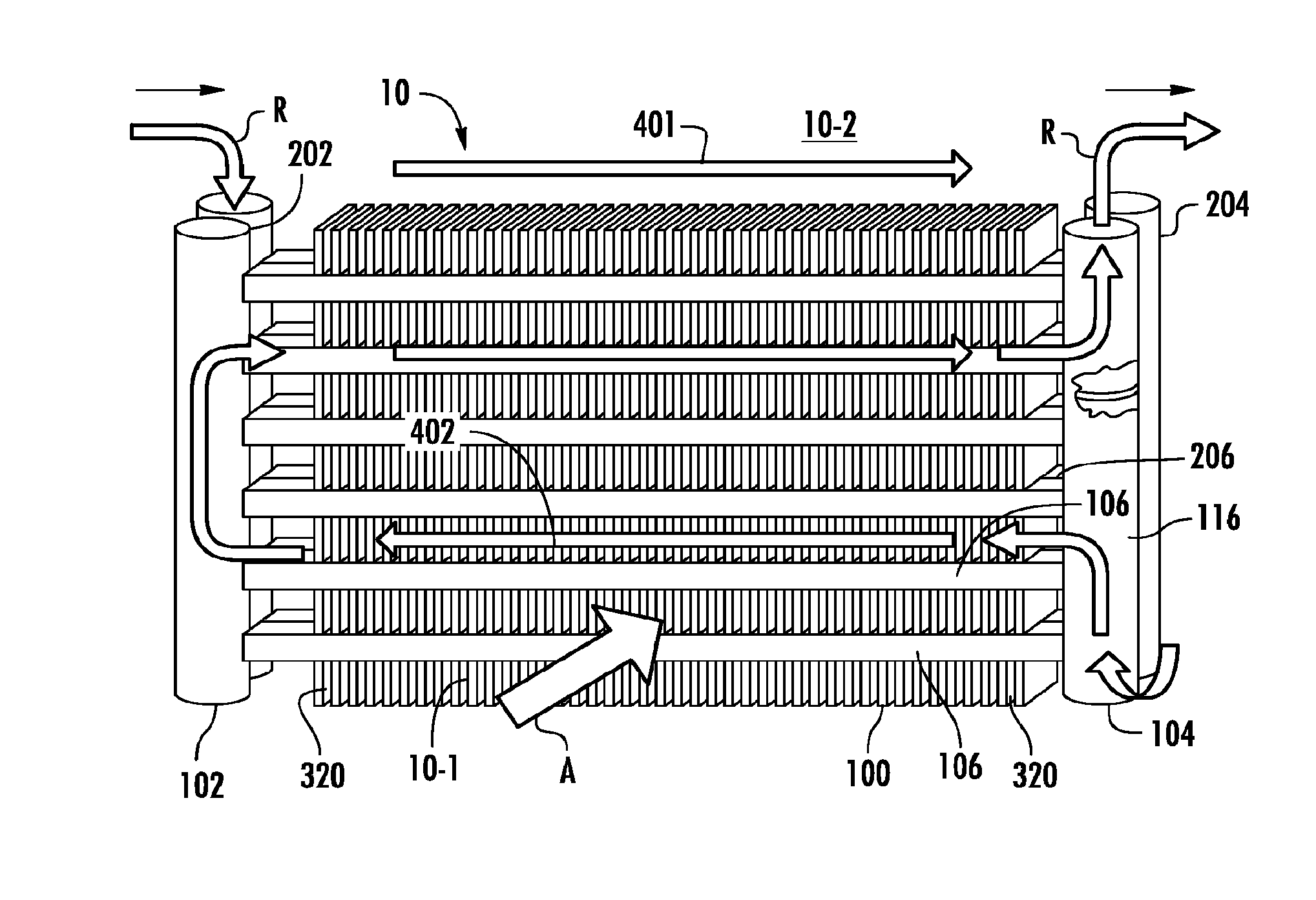
[0030] An exemplary embodiment of a multiple bank flattened tube finned heat exchanger unit in accordance with the disclosure, generally designated 10, is depicted in perspective illustration in FIG. 1. As depicted therein, the multiple bank flattened tube finned heat exchanger 10 includes a first tube bank 100 and a second tube bank 200 that is disposed behind the first tube bank 100, that is downstream with respect to air flow, A, through the heat exchanger. The first tube bank 100 may also be referred to herein as the front heat exchanger slab 100 and the second tube bank 200 may also be referred to herein as the rear heat exchanger slab 200.
[0031] The first tube bank 100 includes a first manifold 102, a second manifold 104 spaced apart from the first manifold 102, and a plurality of heat exchange tube segments 106, including at least a first and a second tube segment, extending longitudinally in spaced parallel relationship between and connecting the first manifold 102 and the second manifold 104 in fluid communication. The second tube bank 200 includes a first manifold 202, a second manifold 204 spaced apart from the first manifold 202, and a plurality of heat exchange tube segments 206, including at least a first and a second tube segment, extending longitudinally in spaced parallel relationship between and connecting the first manifold 202 and the second manifold 204 in fluid communication. As will be described in further detail herein later, each set of manifolds 102, 202 and 104, 204 disposed at either side of the dual bank heat exchanger 10 may comprise separate paired manifolds, may comprise separate chambers within an integral one-piece folded manifold assembly or may comprise separate chambers within an integral fabricated (e.g. extruded, drawn, rolled and welded) manifold assembly. Each tube bank 100, 200 may further include "dummy" tubes (not shown) extending between its first and second manifolds at the top of the tube bank and at the bottom of the tube bank. These "dummy" tubes do not convey refrigerant flow, but add structural support to the tube bank and protect the uppermost and lowermost fins.
[0032] Referring now to FIG. 2, each of the heat exchange tube segments 106, 206 comprises a flattened heat exchange tube having a leading edge 108, 208, a trailing edge 110, 210, an upper surface 112, 212, and a lower surface 114, 214. The leading edge 108, 208 of each heat exchange tube segment 106, 206 is upstream of its respective trailing edge 110, 210 with respect to airflow through the heat exchanger 10. In the embodiment depicted in FIG. 2, the respective leading and trailing portions of the flattened tube segments 106, 206 are rounded thereby providing blunt leading edges 108, 208 and trailing edges 110, 210. However, it is to be understood that the respective leading and trailing portions of the flattened tube segments 106, 206 may be formed in other configurations.
[0033] The interior flow passage of each of the heat exchange tube segments 106, 206 of the first and second tube banks 100, 200, respectively, may be divided by interior walls into a plurality of discrete flow channels 120, 220 that extend longitudinally the length of the tube from an inlet end of the tube to an outlet end of the tube and establish fluid communication between the respective headers of the first and the second tube banks 100, 200. In the embodiment of the multi-channel heat exchange tube segments 106, 206 depicted in FIG. 2, the heat exchange tube segments 206 of the second tube bank 200 have a greater width than the heat exchange tube segments 106 of the first tube bank 100. Also, the interior flow passages of the wider heat exchange tube segments 206 may be divided into a greater number of discrete flow channels 220 than the number of discrete flow channels 120 into which the interior flow passages of the heat exchange tube segments 106 are divided. The flow channels 120, 220 may have a circular cross-section, a rectangular cross-section or other non-circular cross-section.
[0034] The second tube bank 200, i.e. the rear heat exchanger slab, is disposed behind the first tube bank 100, i.e. the front heat exchanger slab, with respect to the airflow direction, with each heat exchange tube segment 106 directly aligned with a respective heat exchange tube segment 206 and with the leading edges 208 of the heat exchange tube segments 206 of the second tube bank 200 spaced from the trailing edges 110 of the heat exchange tube segments of the first tube bank 100 by a desired spacing, G. A spacer or a plurality of spacers disposed at longitudinally spaced intervals may be provided between the trailing edges 110 of the heat exchange tube segments 106 and the leading edges 208 of the heat exchange tube segments 206 to maintain the desired spacing, G, during brazing of the preassembled heat exchanger unit 10 in a brazing furnace.
[0035] In the embodiment depicted in FIG. 2, an elongated web 40 or a plurality of spaced web members 40 span the desired spacing, G, along at least of portion of the length of each aligned set of heat exchange tube segments 106, 206. For a further description of a dual bank, flattened tube finned heat exchanger unit wherein the heat exchange tubes 106 of the first tube bank 100 and the heat exchange tubes 206 of the second tube bank 200 are connected by an elongated web or a plurality of web members, reference is made to U.S. provisional application Ser. No. 61/593,979, filed Feb. 2, 2012, the entire disclosure of which is hereby incorporated herein by reference.
[0036] Referring still to FIGS. 1 and 2, the flattened tube finned heat exchanger 10 disclosed herein further includes a plurality of folded fins 320. Each folded fin 320 is formed of a single continuous strip of fin material tightly folded in a ribbon-like serpentine fashion thereby providing a plurality of closely spaced fins 322 that extend generally orthogonal to the flattened heat exchange tubes 106, 206. Typically, the fin density of the closely spaced fins 322 of each continuous folded fin 320 may be about 16 to 25 fins per inch, but higher or lower fin densities may also be used. Heat exchange between the refrigerant flow, R, and air flow, A, occurs through the outside surfaces 112, 114 and 212, 214, respectively, of the heat exchange tube segments 106, 206, collectively forming the primary heat exchange surface, and also through the heat exchange surface of the fins 322 of the folded fin 320, which forms the secondary heat exchange surface.
[0037] In the depicted embodiment, the depth of each of the ribbon-like folded fin 320 extends at least from the leading edge 108 of the first tube bank 100 to the trailing edge of 210 of the second bank 200, and may overhang the leading edge 108 of the first tube bank 100 or/and trailing edge 208 of the second tube bank 200 as desired. Thus, when a folded fin 320 is installed between a set of adjacent multiple tube, flattened heat exchange tube assemblies 240 in the array of tube assemblies of the assembled heat exchanger 10, a first section 324 of each fin 322 is disposed within the first tube bank 100, a second section 326 of each fin 322 spans the spacing, G, between the trailing edge 110 of the first tube bank 100 and the leading edge 208 of the second tube bank 200, and a third section 328 of each fin 322 is disposed within the second tube bank 200. In an embodiment, each fin 322 of the folded fin 320 may be provided with louvers 330, 332 formed in the first and third sections, respectively, of each fin 322.
[0038] The multiple bank, flattened tube heat exchange unit 10 disclosed herein is depicted in a cross-counterflow arrangement wherein refrigerant (labeled "R") from a refrigerant circuit (not shown) of a refrigerant vapor compression system (not shown) passes through the manifolds and heat exchange tube segments of the tube banks 100, 200, in a manner to be described in further detail hereinafter, in heat exchange relationship with a cooling media, most commonly ambient air, flowing through the airside of the heat exchanger 10 in the direction indicated by the arrow labeled "A" that passes over the outside surfaces of the heat exchange tube segments 106, 206 and the surfaces of the folded fin strips 320. The air flow first passes transversely across the upper and lower horizontal surfaces 112, 114 of the heat exchange tube segments 106 of the first tube bank, and then passes transversely across the upper and lower horizontal surfaces 212, 214 of the heat exchange tube segments 206 of the second tube bank 200. The refrigerant passes in cross-counterflow arrangement to the airflow, in that the refrigerant flow passes first through the second tube bank 200 and then through the first tube bank 100. The multiple tube bank, flattened tube finned heat exchanger 10 having a cross-counterflow circuit arrangement yields superior heat exchange performance, as compared to the crossflow or cross-parallel flow circuit arrangements, as well as allows for flexibility to manage the refrigerant side pressure drop via implementation of tubes of various widths within the first tube bank 100 and the second tube bank 200.
[0039] In the embodiment depicted in FIGS. 1 and 3, the second tube bank 200, i.e. the rear heat exchanger slab with respect to air flow, has a single-pass refrigerant circuit configuration and the first tube bank 100, i.e. the front heat exchanger slab with respect to air flow, has a two pass configuration. Refrigerant flow passes from a refrigerant circuit (not shown) into the first manifold 202 of the second tube bank 200 through at least one refrigerant inlet 222 (FIG. 3), passes through the heat exchange tube segments 206 into the second manifold 204 of the second tube bank 200, then passes into the second manifold 104 of the first tube bank 100, thence through a lower set of the heat exchange segments 106 into the first manifold 102 of the first tube bank 100, thence back to the second manifold 104 through an upper set of the heat exchange tubes 106, and thence passes back to the refrigerant circuit through at least one refrigerant outlet 122.
[0040] In the embodiment depicted in FIG. 4, the second tube bank 200, i.e., the rear heat exchanger slab with respect to air flow, has a single-pass refrigerant circuit configuration and the first tube bank 100, i.e. the front heat exchanger slab with respect to air flow, also has a single pass configuration. Refrigerant flow passes from a refrigerant circuit (not shown) into the first manifold 202 of the second tube bank 200 through at least one refrigerant inlet 222, passes through the heat exchange tube segments 206 into the second manifold 204 of the second tube bank 200, then passes into the second manifold 104 of the first tube bank 100, thence passes through the heat exchange segments 106 into the first manifold 102 of the first tube bank 100, and thence passes back to the refrigerant circuit through at least one refrigerant outlet 122.
[0041] In the embodiments depicted in FIGS. 1, 3 and 4, the neighboring second manifolds 104 and 204 are connected in fluid flow communication such that refrigerant may flow from the interior of the second manifold 204 of the second tube bank 200 into the interior of the second manifold 104 of the first tube bank 100. In an embodiment, the second manifold 104 of the first tube bank 100 has a plurality of longitudinally aligned ports, e.g., holes 244 (FIG. 5), drilled, milled or punched through the wall thereof and disposed at longitudinally spaced intervals. Similarly, the second manifold 204 of the second tube bank 200 has a plurality of longitudinally aligned ports, e.g., holes 246 (FIG. 5), equal in number to the plurality of holes 244 in the second manifold 104 of the first tube bank 100, drilled, milled or punched through the wall thereof and disposed at longitudinally spaced intervals. Each port 244 forms a flow passage through the wall of the second manifold 104 and each port 246 forms a flow passage through the wall of the second manifold 204. When the heat exchanger unit 10 is assembled, each flow passage, i.e. port 246, in the second manifold 204 aligns with a respective one of the flow passages, i.e. port 244, of the first manifold 104. It should be understood that the ports 244, 246 may be holes of the same size, however certain design configuration may benefit of the holes being of different sizes.
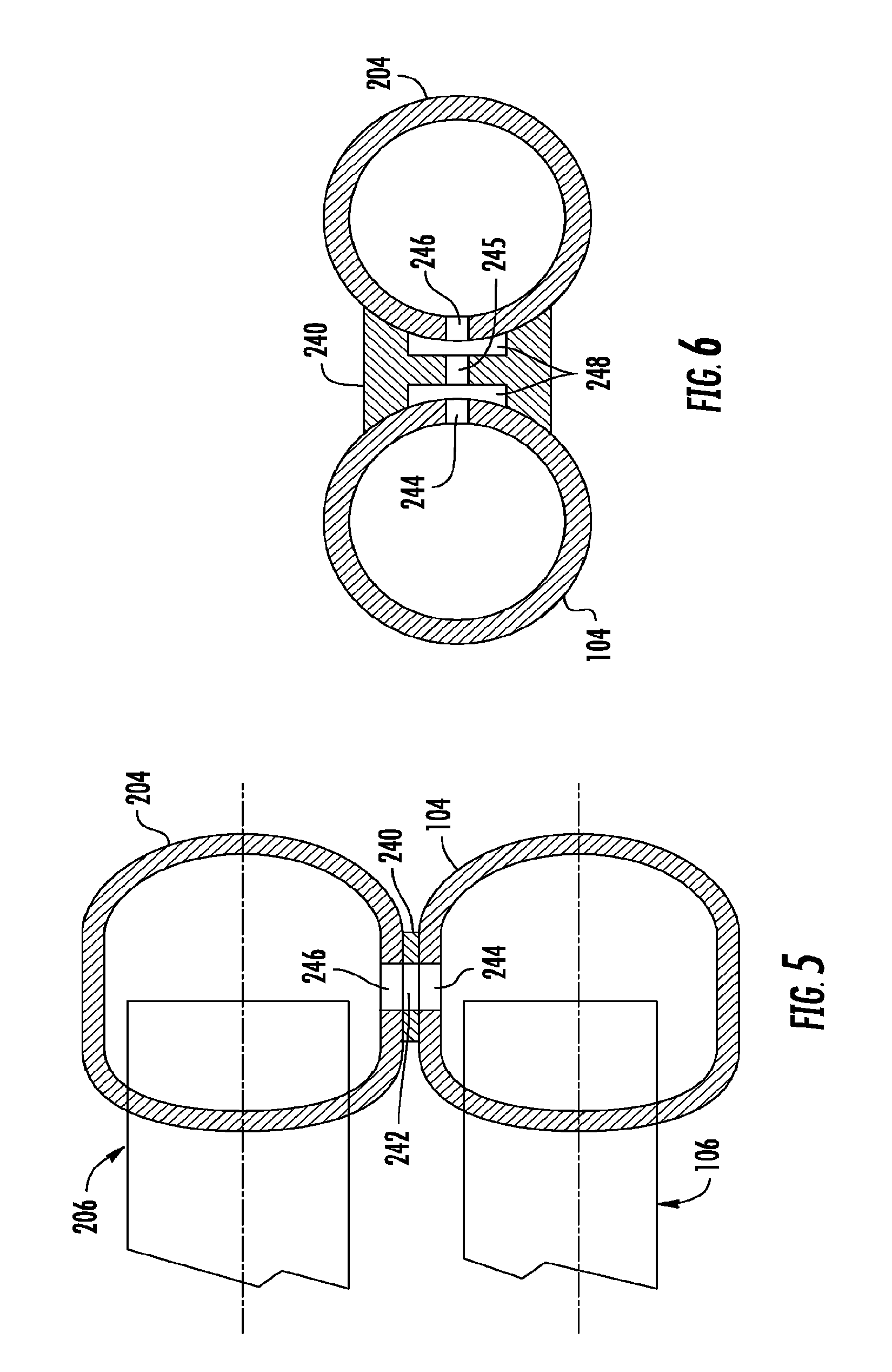
[0042] In the embodiment depicted in FIG. 5, a block insert 240 having a central passage 242 extending longitudinally therethrough is positioned between the manifolds 104 and 204 is positioned such that the central passage 242 aligns with ports 244 and 246 formed through the respective walls of the manifolds 104 and 204, respectively, and spans the longitudinally expanse of the longitudinally spaced ports 244 and 246. So assembled, a plurality of continuous flow passages are established through which refrigerant may pass from the interior of the second manifold 204 of the second tube bank 200 through the port 246, thence through the central passage 242 of the block insert 240, and thence through the port 244 into the interior of the second manifold 104 of the first tube bank 100. In this embodiment, the block insert 240 may comprise a longitudinally elongated block having a single longitudinally extending slot forming a longitudinally elongated central passage 242 that interfaces with all of the plurality of ports 244 and 246. Alternatively, a longitudinally elongated central passage 242 that interfaces with ports 244 and 246 may be represented by a plurality of slots, each slot spanning only a portion of the aligned ports 244 and 246. In the embodiment depicted in FIG. 5, the first and second manifolds 104, 204 are both generally D-shaped manifolds disposed in back-to-back spaced relationship with a generally rectangular block insert 242 disposed between the first and second manifolds 104, 204.
[0043] In the embodiment depicted in FIG. 6, the first and second manifolds 104, 106 are both cylindrical manifolds disposed in side-to-side spaced relationship with a contoured block insert 240. In this embodiment, the side faces 248 of the block insert 240 are contoured concave inwardly to match and mate with the contour of the external surface of the respective abutting second manifolds. In this embodiment, the block insert 240 may comprise a longitudinally elongated block having a pair of laterally spaced, longitudinally extending slots forming longitudinally elongated flow passages 248 and having a plurality of longitudinally spaced bores 245 interconnecting the laterally spaced flow passages 248 in fluid communication. The bores 245 may be disposed in alignment with the ports 244 and 246 in the first and second manifolds 104, 204, respectively. In either of the embodiments depicted in FIGS. 5 and 6, the block insert 240 is metallurgically bonded, for example by brazing or welding, to each of the second manifolds 104 and 204. It should be understood that brazing can be accomplished during furnace brazing of the entire heat exchanger construction.
[0044] In the embodiments depicted in FIGS. 7 and 8, the second manifolds 104 and 204 are connected in fluid communication through a plurality of individual tubular members 250 interconnecting the plurality of aligned pairs of ports 244 and 246 in the first and second manifolds 104, 204, respectively. Each tubular member 250 extends through a respective one of the plurality of longitudinally spaced sets of aligned ports 244 and 246, whereby each tubular member forms a flow passage 252 between the interior of the second manifold 204 of the second tube bank 200 and the interior of the second manifold 104 of the first tube bank 100. In the embodiments as depicted in FIGS. 7 and 8, the tubular member 250 has a tubular first end 256 and a tubular second end 258 and a radially outwardly directed flange 260 extending circumferentially about a mid-portion of the tubular member 250 between the first end 256 and the second end 258. In the embodiment as depicted in FIG. 7, the first end 256 extends through a port 244 in the manifold 104 and the second end 258 extends through a port 246 in the manifold 24 and each tubular member 250 may be metallurgically bonded to the manifolds 104 and 204, for example by brazing during brazing of the entire heat exchanger assembly in a brazing furnace. Additionally, the thickness of the flange 260 may be sized to ensure a desired spacing between the second manifolds 104 and 204.
[0045] In the embodiment depicted in FIG. 8, the first end 256 of each tubular member 250 is threaded and is inserted into a respective one of a plurality of threaded sockets provided in a longitudinally extending block 254. Each socket is aligned with a respective one of the ports 244 in the manifold 104. The second end 258 of each tubular member 250 is inserted into a respective one of the ports 246 in the manifold 204. The block 254 and the second end 258 are metallurgically bonded to the manifold 104 and the manifold 204, respectively, for example by brazing during brazing of the entire heat exchanger assembly in a brazing furnace. In this embodiment, the flange 260 may be hexagonal, octagonal or otherwise shaped to accommodate a wrench or other tool by which the tubular member 250 may be screwed into a respective one of the threaded holes of the longitudinally extended block 254.
[0046] In each of the embodiments depicted in FIGS. 5-8, the paired tubular manifolds 104 and 204 in fluid communication through the plurality of longitudinally spaced, aligned and interfacing sets of ports 244 and 246 that are connected through a passage or passages provided in one or more inserts 240, 260 disposed between and brazed to the paired manifolds 104, 204, rather than being connected via external piping. The size, number and spacing of the ports 244, 246, as well as the thickness of the wall of the tubular manifolds 104, 204, may be selected to satisfy structural considerations. The cross-sectional area of the ports 244, 246 may be sized to satisfy thermo-hydraulic considerations.
[0047] Referring now to FIG. 9, there is depicted an embodiment of a fabricated integral manifold assembly 270 wherein one of the second manifolds 104, 204 is a full tubular manifold and the other of the second manifolds 104, 204 is a partially tubular manifold being open longitudinally along its entire length over a sector of the circumference of the manifold. The fully tubular manifold, shown in FIG. 9 as being the second manifold 204 of the second manifold 200, has a plurality of longitudinally aligned holes or slots 274 drilled, milled or punched through the wall thereof and disposed at longitudinally spaced intervals. The partially tubular manifold, shown in FIG. 9 as being the second manifold 104 of the first manifold 100, is disposed side-by-side along the fully tubular manifold 204 with the longitudinally open sector straddling the plurality of holes or slots 274 machined through the wall of the second manifold 204 there by establishing fluid flow communication between the respective interior chambers of the second manifolds 104 and 204.
[0048] The partially tubular manifold and the fully tubular manifold are metallurgically bonded, such as by brazing or welding, along the interfaces of the partially tubular manifold with the fully tubular manifold to form the integral manifold assembly 270. A conventional roll and weld process may be used for both the fully tubular manifold and the partially tubular manifold. The longitudinal sides 276 extending along the open sector of the partially tubular manifold may be flared outwardly and contoured to provide a mating interface with the fully tubular manifold.
[0049] Referring now to FIGS. 10-11, there are depicted various exemplary embodiments of a fabricated integral manifold assembly 270 wherein at least one or both of the second manifolds 104, 204 comprises a partially tubular manifold being open longitudinally along its entire length or a portion of the entire length over a sector of the circumference/perimeter of the manifold. The two manifolds 104, 204, which may be formed by extrusion, are metallurgically bonded together along a brazing joint 275 to form the fabricated integral manifold assembly 270. In the embodiments shown in FIGS. 10A and 10B, the manifolds 104 and 204 are extruded with flanges 272 and 276, respectively, flanking their respective longitudinally extending open portions. The manifolds 104 and 204 are assembled together with the flanges of one of the manifolds 104, 204 inserted within the flanges of the other of the manifolds 104, 204 to interface along a joint 275 and to form a flow passage 274 interconnecting the respective interiors of the manifolds 104, 204. The manifolds 104, 204 can be metallurgically bonded together along the joint 275 by brazing during brazing of the entire heat exchanger assembly in a brazing furnace. In an embodiment, both of the manifolds 104, 204 are extruded as partially tubular manifolds being open longitudinally along its entire length over a sector of the circumference/perimeter of the manifold. In an embodiment, one of the manifolds, i.e. the manifold 104 in FIG. 10A and the manifold 204 in FIG. 10B, is extruded as a circumferentially closed tubular member having a plurality of longitudinally spaced, aligned holes that are disposed in fluid communication with the open sector of the other manifold when the heat exchanger is assembled prior to brazing the entire heat exchanger assembly.
[0050] In the embodiment of the fabricated integral manifold assembly 270 depicted in FIG. 11, the two manifolds 104, 204 are assembled in abutting relationship with their respective open portions facing each other to form a flow passage 274 and with their wall portions flanking their respective open portions interfacing along joints 275 along which the manifolds 104, 204 are metallurgically bonded together along the joint 275 by brazing during brazing of the entire heat exchanger assembly in a brazing furnace. In another embodiment of the fabricated integral manifold assembly depicted in FIG. 11, one or both of the manifolds 104, 204 may be formed as a fully closed tubular member having a plurality of longitudinally spaced, aligned holes instead of being a partially open tubular manifold having a open sector extending the length thereof.
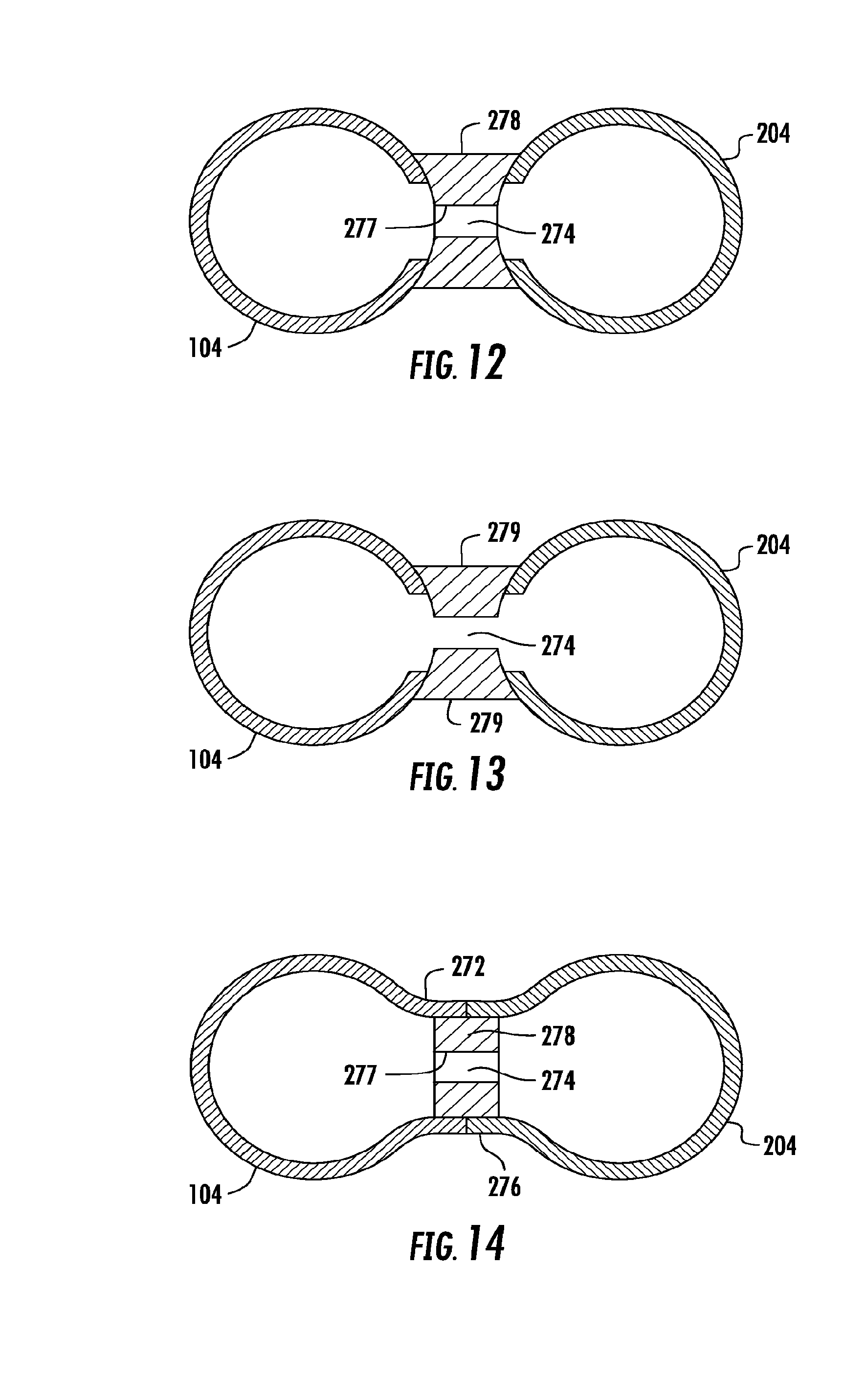
[0051] Referring now to FIGS. 12-14, there are depicted embodiments of a fabricated integral manifold assembly 270 wherein both of the manifolds 104, 204 are formed as partially open tubular manifolds being open longitudinally along its entire length over a sector of the circumference/perimeter of the manifold. In the embodiment of the fabricated integral manifold assembly 270 depicted in FIGS. 12 and 13, the two manifolds 104, 204 are assembled in spaced relationship with their respective open portions facing each other. In the embodiment depicted in FIG. 12, a longitudinally extending block insert 278 having a plurality of bores 277 extending transversely therethrough is disposed between the two manifolds 104, 204 to form a plurality of flow passages 274 between the interiors of the manifolds 104, 204. The block insert 278 is brazed to the interfacing outer wall portions of the manifolds 104, 204 to form joints 275. In the embodiment of the fabricated integral manifold assembly 270 depicted in FIG. 13, a pair of longitudinally extending block inserts 279 is disposed in spaced relationship between the spaced open manifolds 104, 204 so as to form a flow passage 274 between the interiors of the manifolds 104, 204. The block inserts 279 are brazed to the interfacing wall portions of the manifolds 104, 204 to form joints 275. In the embodiment depicted in FIG. 14, a longitudinally extending block insert 278 having a plurality of longitudinally spaced bores 277 extending transversely therethrough is disposed internally between the respective flanges 272, 276 of the two manifolds 104, 204 to form a plurality of flow passages 274 between the interiors of the manifolds 104, 204. The block insert 278 is brazed to the interfacing inner wall portion of the flanges of the manifolds 104, 204.
[0052] The manifold assembly disclosed herein may also be formed from a single metal sheet as an integral folded manifold assembly. Referring to a FIG. 15, the single sheet 286 of aluminum alloy from which the integral folded manifold assembly is formed is clad with a layer 285 of suitable brazing alloy and provided with a plurality of first ports 281 and a plurality of second ports 283. The ports 281 and 283 may comprise pre-drilled, pre-milled or pre-punched round holes or pre-fabricated elliptical, racetrack, rectangular, triangular or any other cross-section suitable for a particular manufacturing process and heat exchanger design configuration. To form the integral folded manifold assembly 280, the sheet 286 is folded upon itself such as the wall portions 282, 284 interface in side-by-side relationship such as illustrated in FIG. 10 or in FIG. 11, whereby each one of the plurality of first ports 281 registers with a corresponding one of the plurality of second ports 283. The interfacing surfaces of the cladded wall portions 282 and 284 are metallurgically bonded together when the assembled heat exchanger unit 10 is brazed in the brazing furnace, for example a controlled atmosphere brazing furnace.
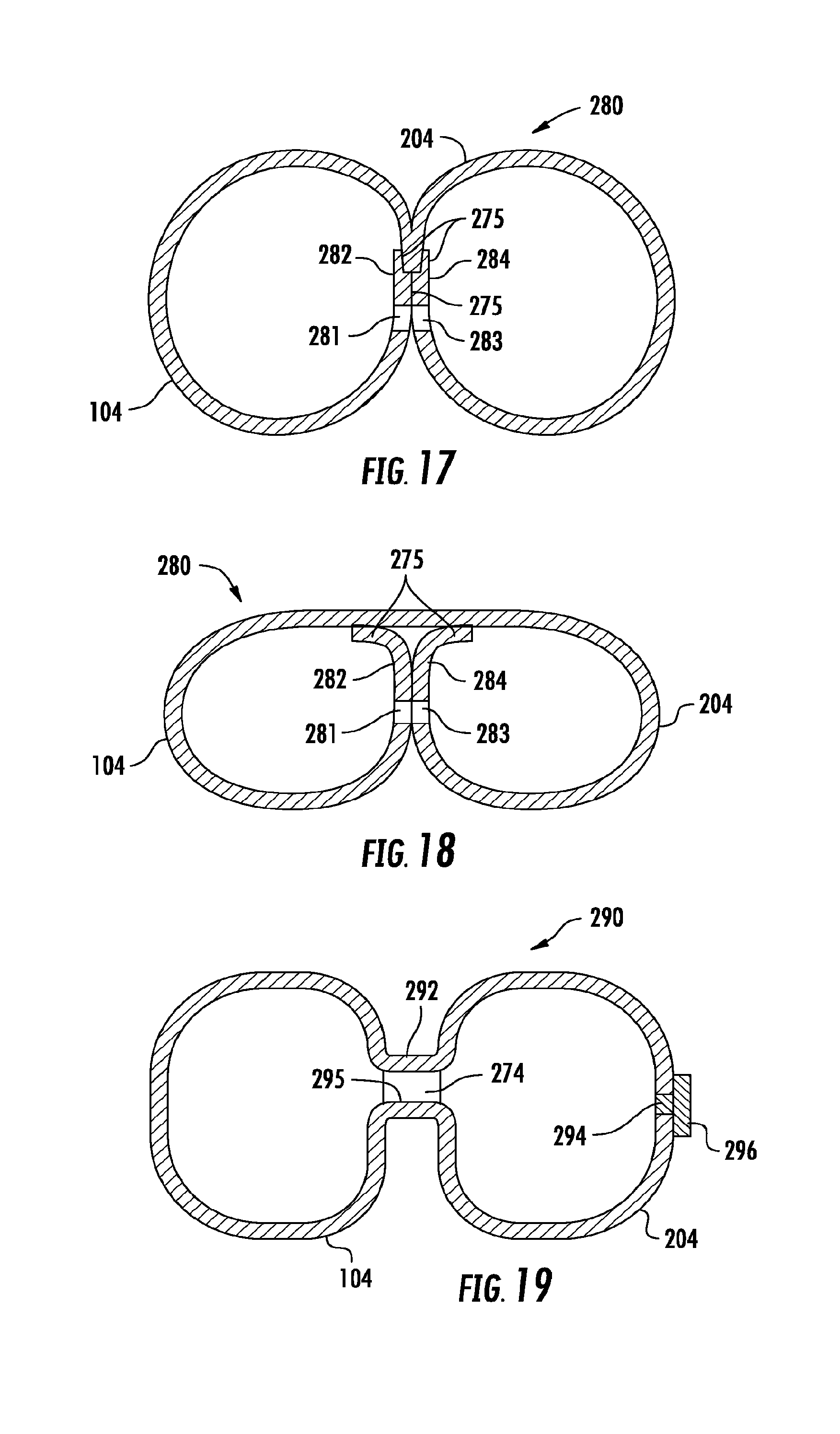
[0053] Referring now to FIGS. 16, 17 and 18, there are depicted various exemplary embodiments of an integral folded manifold assembly 280 formed from a single folded sheet 286. The first manifold 104 and the second manifold 204 are formed in an integral folded manifold assembly 280 with respective wall portions 282, 284 of the manifolds 104, 204 disposed in interfacing side-by-side abutting relationship with a plurality of first ports 281 formed in the wall portion 282 being in registration with a similar plurality of second ports 283 formed in the interfacing wall portion 284. The respective pairs of aligned ports 281 and 283 form flow passages establishing internal fluid flow communication through which refrigerant may pass from the second manifold 204 into the first manifold 104. In each embodiment depicted in FIGS. 16, 17 and 18, the integral folded manifold assembly 280 is formed by folding a single sheet 286 of clad aluminum alloy onto itself and metallurgically bonding the overlapping or abutting portions of the folded sheet to each other along a brazing joint 275. This allows for a single braze operation of the manifold and heat exchanger core during the furnace braze process. Furthermore, one set of the first ports 281 or second ports 283 can be slightly oversized in comparison to the other of the first ports 281 or the second ports 283 for easier alignment during the manifold forming process.
[0054] The manifold assembly disclosed herein may also be formed as an extruded integral dual barrel tubular manifold assembly 290, for example as depicted in FIG. 19. The extruded manifold assembly 290 includes a first tubular barrel forming the manifold 104, a second tubular barrel forming the manifold 204, and a central web portion 292 joining the tubular barrels along the longitudinal extent of the assembly. A plurality of longitudinally spaced bores 295 extend transversely through the central web portion 292 to provide a plurality of flow passages 274 connecting the respective interiors of the manifolds 104, 204. The bores 295 may be drilled through the central web portion 292 of the extruded manifold assembly 290 by first providing a series of longitudinal spaced holes 294, for example by punching, drilling or milling, in the wall of one of the manifolds 104, 204 opposite the central web portion 292. A drill bit is then inserted through each hole 294 and a bore 295 is drilled through the central web portion 292. Each of the holes 294 is then closed by inserting a plug 296 into each hole 294. The inserted plugs 296 are metallurgically bonded to the manifold assembly during the brazing of the heat exchanger assembly in a brazing furnace.
[0055] The manifold assembly disclosed herein may also be fabricated as a flat manifold rather than as paired tubular manifolds as in the previously described embodiments. Referring to FIGS. 20 and 21, the manifold assembly 380 depicted therein comprises a stamped cover plate 382 metallurically bonded at brazed joints 385 to a flat base plate 384. Flat manifolds have a reduced interior volume as compared to comparable paired tubular manifolds. In refrigeration applications wherein the flat manifold is associated with a condenser heat exchanger, the reduced volume as compared to a comparable paired tubular manifold assembly can reduce refrigerant charge requirements up to 50%.
[0056] In the embodiment depicted in FIG. 20, the cover plate 382 is stamped to define when joined to the flat base plate 384 a single longitudinally extending chamber into which both the plurality of heat exchange tube segments 106 and the plurality of heat exchange tube segments 206 open so that refrigerant may flow from the heat exchange tube segments 106 into the heat exchange tube segments 206. In the embodiment depicted in FIG. 21, the cover plate 382 is stamped to define when joined to the flat base plate 384 a pair of longitudinally extending chambers 387 and 388 extending in parallel spaced relationship. In this embodiment, the heat exchange tube segments 106 open into chamber 387 and the heat exchange tube segments 206 open into chamber 388. Cross-over flow passages 389 may be stamped in the cover plate 382 at one or more locations along the length of the longitudinally extending cover plate 382 as desired to provide flow communication between chamber 387 and chamber 388. The location of the cross-over passages 389 determines the flow circuitry of the refrigerant passing between the chambers 387 and 388.
[0057] As depicted in FIGS. 22A-D, the flat manifold 380 may also be formed integrally from a single metal plate 386 folded into a desired shape with overlapping ends which are metallurgically bonded along a brazed joint 385. Openings for receiving the heat exchange tube segments 106 and 206 may be punched or otherwise formed through the single plate 386 prior to or after folding the plate 386 into the desired shape. The single metal plate 386 may comprise an aluminum alloy plate clad with a suitable cladding material to facilitate brazing the overlapping end portions of the plate 386 together and also brazing the heat exchange tube segments 106 and 206 to the folded plate manifold.
[0058] Although described herein in application to the second manifolds 104, 204, it is to be understood that in some embodiments of the multiple bank heat exchanger 10, the first manifolds 102 and 202 may also be formed as an integral manifold having a chamber defining the first manifold 102 and a chamber forming the first manifold 202.
[0059] While the present invention has been particularly shown and described with reference to the exemplary embodiments as illustrated in the drawing, it will be recognized by those skilled in the art that various modifications may be made without departing from the spirit and scope of the invention. Therefore, it is intended that the present disclosure not be limited to the particular embodiment(s) disclosed as, but that the disclosure will include all embodiments falling within the scope of the appended claims.
* * * * *
D00000
D00001
D00002
D00003
D00004
D00005
D00006
D00007
D00008
D00009
XML
uspto.report is an independent third-party trademark research tool that is not affiliated, endorsed, or sponsored by the United States Patent and Trademark Office (USPTO) or any other governmental organization. The information provided by uspto.report is based on publicly available data at the time of writing and is intended for informational purposes only.
While we strive to provide accurate and up-to-date information, we do not guarantee the accuracy, completeness, reliability, or suitability of the information displayed on this site. The use of this site is at your own risk. Any reliance you place on such information is therefore strictly at your own risk.
All official trademark data, including owner information, should be verified by visiting the official USPTO website at www.uspto.gov. This site is not intended to replace professional legal advice and should not be used as a substitute for consulting with a legal professional who is knowledgeable about trademark law.