Oil Separators
SUZUKI; Takuya ; et al.
U.S. patent application number 16/214263 was filed with the patent office on 2019-06-13 for oil separators. This patent application is currently assigned to KOJIMA INDUSTRIES CORPORATION. The applicant listed for this patent is KOJIMA INDUSTRIES CORPORATION, TOYOTA JIDOSHA KABUSHIKI KAISHA. Invention is credited to Masami ISHIKAWA, Hirotaka MATSUDA, Tomoki NAKAMURA, Takuya SUZUKI, Naoya TAMURA.
| Application Number | 20190178122 16/214263 |
| Document ID | / |
| Family ID | 66735188 |
| Filed Date | 2019-06-13 |


| United States Patent Application | 20190178122 |
| Kind Code | A1 |
| SUZUKI; Takuya ; et al. | June 13, 2019 |
Oil Separators
Abstract
An oil separator for trapping oil mist contained in blow-by gas includes a separation plate, an upstream oil-mist trapping chamber, and a downstream oil-mist trapping chamber. The upstream and downstream oil-mist trapping chambers are divided by the separation plate. The upstream oil-mist trapping chamber communicates with a flow inlet for blow-by gas. The downstream oil-mist trapping chamber communicates with the upstream oil-mist trapping chamber and communicates with a flow outlet for blow-by gas. A return port formed through the separation plate returns oil mist trapped in the downstream oil-mist trapping chamber into the upstream oil-mist trapping chamber. The return port is positioned vertically above the bottom surface of the upstream oil-mist trapping chamber and is positioned at substantially the same vertical level as the lowermost portion of the bottom surface of the downstream oil-mist trapping chamber.
| Inventors: | SUZUKI; Takuya; (Toyota-shi, JP) ; MATSUDA; Hirotaka; (Toyota-shi, JP) ; TAMURA; Naoya; (Toyota-shi, JP) ; ISHIKAWA; Masami; (Aichi-gun, JP) ; NAKAMURA; Tomoki; (Okazaki-shi, JP) | ||||||||||
| Applicant: |
|
||||||||||
|---|---|---|---|---|---|---|---|---|---|---|---|
| Assignee: | KOJIMA INDUSTRIES
CORPORATION Toyota-shi JP TOYOTA JIDOSHA KABUSHIKI KAISHA Toyota-shi JP |
||||||||||
| Family ID: | 66735188 | ||||||||||
| Appl. No.: | 16/214263 | ||||||||||
| Filed: | December 10, 2018 |
| Current U.S. Class: | 1/1 |
| Current CPC Class: | F01M 13/04 20130101; F01M 13/0405 20130101; F01M 2013/0461 20130101 |
| International Class: | F01M 13/04 20060101 F01M013/04 |
Foreign Application Data
| Date | Code | Application Number |
|---|---|---|
| Dec 11, 2017 | JP | 2017-236918 |
Claims
1. An oil separator for trapping oil mist contained in blow-by gas, the oil separator comprising: an upstream oil-mist trapping chamber in fluid communication with a flow inlet for blow-by gas; a downstream oil-mist trapping chamber positioned adjacent to the upstream oil-mist trapping chamber and separated from the upstream oil-mist trapping chamber by a separation plate; a communication port in fluid communication with the upstream oil-mist trapping chamber and the downstream oil-mist trapping chamber; a flow outlet configured to allow blow-by gas from the downstream oil-mist trapping chamber to flow outside of the oil separator; and a return port extending through the separation plate and configured to allow oil mist trapped in the downstream oil-mist trapping chamber to return into the upstream oil-mist trapping chamber; wherein the return port is positioned above a bottom surface of the upstream oil-mist trapping chamber and is positioned at substantially the same height as a lowermost portion of a bottom surface of the downstream oil-mist trapping chamber.
2. The oil separator of claim 1, wherein the separation plate comprises: a wall surface facing opposite to the upstream oil-mist trapping chamber; and a rib formed on the wall surface proximal the return port, wherein the rib is configured to prevent blow-by gas from flowing from the upstream oil-mist trapping chamber into the downstream oil-mist trapping chamber through the return port.
3. The oil separator of claim 2, wherein the rib has a U-shape configuration and extends along the return port.
4. The oil separator of claim 2, wherein the rib has a U-shape configuration and extends in an arc shape around the return port.
5. The oil separator of claim 4, wherein the arc extends more than 180 degrees about the return port.
6. An oil separator for trapping oil mist contained in blow-by gas, the oil separator comprising: a liquid oil trapping chamber including at least one hole configured to allow liquid oil to exit under the force of gravity; an upstream oil-mist trapping chamber in fluid communication with the liquid oil trapping chamber; a downstream oil-mist trapping chamber positioned adjacent to the upstream oil-mist trapping chamber and separated from the upstream oil-mist trapping chamber by a separation plate; a communication port configured to allow the upstream oil-mist trapping chamber to communicate with the downstream oil-mist trapping chamber; a flow outlet configured to allow blow-by gas from the downstream oil-mist trapping chamber to flow outside of the oil separator; and a return port formed through the separation plate and configured to allow oil mist trapped in the downstream oil-mist trapping chamber to return into the upstream oil-mist trapping chamber; wherein the return port is positioned vertically above a bottom surface of the upstream oil-mist trapping chamber and is positioned at substantially the same vertical level as a lowermost portion of a bottom surface of the downstream oil-mist trapping chamber.
7. An oil separator for trapping oil mist contained in blow-by gas, the oil separator comprising: a liquid oil trapping chamber; an upstream oil-mist trapping chamber downstream of the liquid oil trapping chamber, wherein the liquid oil trapping chamber is in fluid communication with a flow inlet for blow-by gas from the upstream liquid oil trapping chamber; a downstream oil-mist trapping chamber positioned adjacent to the upstream oil-mist trapping chamber and separated from the upstream oil-mist trapping chamber by a separation plate; a communication port configured to allow the upstream oil-mist trapping chamber to communicate with the downstream oil-mist trapping chamber; a flow outlet configured to allow blow-by gas from the downstream oil-mist trapping chamber to flow outside of the oil separator; and a return port formed through the separation plate such that the return port allows oil mist trapped in the downstream oil-mist trapping chamber to return into the upstream oil-mist trapping chamber; wherein the return port is located at a level higher than a bottom surface of the upstream oil-mist trapping chamber and is positioned at substantially the same level as a lowermost portion of a bottom surface of the downstream oil-mist trapping chamber.
8. The oil separator of claim 7, wherein the liquid oil trapping chamber includes two holes formed in a bottom portion thereof, wherein the two holes are configured to allow liquid oil to exit the liquid oil trapping chamber under the force of gravity.
9. The oil separator claim 8, wherein the two holes formed in the bottom portion of the liquid oil trapping chamber are laterally spaced apart.
10. The oil separator of claim 9, wherein a first collision wall extends obliquely and upward from proximal a center of the two holes and forms a barrier for large particle size liquid oil contained in blow-by gas, wherein the first collision wall is made of resin material such that the oil adheres thereto.
11. The oil separator of claim 7, wherein the separation plate includes a wall surface facing opposite to the upstream oil-mist trapping chamber and a rib formed on the wall surface proximal the return port such that the rib prevents blow-by gas from flowing from the upstream oil-mist trapping chamber into the downstream oil-mist trapping chamber through the return port.
12. The oil separator of claim 7, wherein the rib has a U-shape configuration and extends about at least a portion of the return port.
13. The oil separator of claim 11, wherein the rib has a U-shape configuration and extends circumferentially in an arc shape around the return port.
14. The oil separator of claim 13, wherein the arc extends angularly more than 180 degrees about the return port.
15. The oil separator of claim 11, wherein the rib is formed in a V-shape configuration.
16. The oil separator of claim 11, wherein the rib is formed in a horseshoe configuration.
17. The oil separator of claim 7, wherein the liquid oil trapping chamber is positioned adjacent to and immediately below the downstream oil-mist trapping chamber.
18. The oil separator of claim 7, wherein the communication port has a square-shaped void configuration.
19. The oil separator of claim 7, wherein the liquid oil trapping chamber is positioned immediately adjacent to the upstream oil-mist trapping chamber.
20. The oil separator of claim 7, wherein the downstream oil-mist trapping chamber is located laterally adjacent to the upstream oil mist trapping chamber, and wherein the downstream oil-mist trapping chamber is located directly above and adjacent to the liquid oil trapping chamber.
Description
CROSS-REFERENCE TO RELATED APPLICATIONS
[0001] This application claims priority to Japanese patent application serial number 2017-236918 filed Dec. 11, 2017, which is hereby incorporated herein by reference in its entirety for all purposes.
BACKGROUND
[0002] The present disclosure relates to an oil separator, and more specifically, it relates to an oil separator to trap oil mist contained in blow-by gas.
[0003] A conventional positive crankcase ventilation (PCV) system, which is employed in an internal combustion engine like an automobile engine, is known in the art. Air pollution may result when blow-by gas (un-combusted gas) leaks and/or is discharged from a gap between a piston ring and a cylinder wall of the engine to the exterior atmosphere during operation of the engine. To prevent such leakage of the blow-by gas, the PCV system collects the blow-by gas and then returns the collected blow-by gas to an air intake system. The returned blow-by gas then undergoes re-combustion within the engine. The blow-by gas contains oil mist, which is lubricant oil such as engine oil dispersed as micro particles. The PCV system includes an oil separator designed to trap the oil mist contained in the blow-by gas and prevent the oil mist from flowing into the air intake system. The oil separator is provided in the middle of a flow passage that connects a crankcase and an air-intake duct.
[0004] A conventional labyrinth-type oil separator 101, as illustrated in FIG. 6, is disclosed, for example, in Japanese Laid-Open Patent Publication No. 2009-68471. As illustrated in FIG. 7, the oil separator 101 includes a lower base 110, a middle base 130, and an upper base 140, where these bases 110, 130, 140 are attached to each other by vibration welding. The oil separator 101 includes a liquid oil trapping chamber 150, a primary oil-mist trapping chamber 151, and a secondary oil-mist trapping chamber 152, where each of the chambers 150, 151, 152 is defined between two of the bases 110, 130, 140. The liquid oil trapping chamber 150 contains a compartmented interior space therein, which is capable of trapping liquid oil with a relatively large particle size (not shown). The primary oil-mist trapping chamber 151 is located downstream of the liquid oil trapping chamber 150 and contains a compartmented interior space therein, which is capable of trapping oil mist with a relatively small particle size (not shown).
[0005] As illustrated in FIG. 7, the secondary oil-mist trapping chamber 152 is arranged adjacent to the primary oil-mist trapping chamber 151 via a separation plate 131 of the middle base 130. The secondary oil-mist trapping chamber 152 is located downstream of the primary oil-mist trapping chamber 151 and contains compartmentalized interior space, which is capable of trapping oil-mist with a relatively small particle size. The separation plate 131 has a first communication port 132, a second communication port 133, and a return port 134. The first communication port 132 allows the liquid oil trapping chamber 150 and the primary oil-mist trapping chamber 151 to communicate with each other. The second communication port 133 allows the primary oil-mist trapping chamber 151 and the secondary oil-mist trapping chamber 152 to communicate with each other. The return port 134 allows communication between the primary oil-mist trapping chamber 151 and the secondary oil-mist trapping chamber 152, so as to allow the oil mist trapped by the secondary oil-mist trapping chamber 152 to return to the primary oil-mist trapping chamber 151.
[0006] Containing more than one oil-mist trapping chambers (the primary oil-mist trapping chamber 151 and the secondary oil-mist trapping chamber 152 in this example), the oil separator provides a passage having a long length for the blow-by gas, which has flown into the oil separator 101. Such a configuration of the oil separator 101, with a long length of passage, can enhance trapping efficiency of the oil mist with a small diameter. The return port 134 allows the oil-mist trapped in the secondary oil-mist trapping chamber 152 to merge with the oil mist trapped in the primary oil-mist trapping chamber 151. The merged, trapped oil may be collected together with the liquid oil trapped in the liquid oil trapping chamber 150. This configuration allows the oil-mist trapped in the secondary oil-mist trapping chamber 152 to be collected without a dedicated collecting passage. As a result, the size of the oil separator 101 may be reduced while the oil separator 101 may efficiently trap and collect the oil mist with a small particle size.
[0007] As illustrated in FIG. 8, the return port 134 is located along the bottom surface 151a of the primary oil-mist trapping chamber 151. Additionally, the return port 134 is located along the lowermost portion 152b of the bottom surface 152a of the secondary oil-mist trapping chamber 152. As a result, the return port 134 may facilitate return of the oil-mist trapped in the secondary oil-mist trapping chamber 152 to the primary oil-mist trapping chamber 151.
[0008] The blow-by gas, however, may contain a massive amount of the liquid oil with a large particle size. In this case, the liquid oil with a large particle size may flow from the liquid oil trapping passage 150 into the primary oil-mist trapping chamber 151 through the first communication port 132. The liquid oil with a large particle size may subsequently flow through the return port 134 (i.e., shortcut) from the primary oil-mist trapping chamber 151 into the secondary oil-mist trapping chamber 152 without passing through the second communication port 133, and may finally flow out of the oil separator 101 through an outlet port 113 at the lower base 110. As a result, the liquid oil with a large particle size may undesirably flow into an internal combustion engine located downstream of the oil separator 101 and may be combusted, which may cause a failure of the internal combustion engine.
SUMMARY
[0009] According to one aspect of the present disclosure, an oil separator for trapping oil mist contained in blow-by gas includes a separation plate, an upstream oil-mist trapping chamber, and a downstream oil-mist trapping chamber. The upstream and downstream oil-mist trapping chambers are divided by the separation plate and are positioned adjacent to each other. The upstream oil-mist trapping chamber communicates with a flow inlet for blow-by gas. The downstream oil-mist trapping chamber communicates with the upstream oil-mist trapping chamber and a flow outlet for blow-by gas. A return port is configured to return oil mist trapped in the downstream oil-mist trapping chamber back into the upstream oil-mist trapping chamber. The return port is formed through the separation plate. The return port is positioned above the bottom surface of the upstream oil-mist trapping chamber and is positioned at substantially the same vertical level as the lowermost portion of the bottom surface of the downstream oil-mist trapping chamber.
[0010] The oil contained in blow-by gas is separated from the blow-by gas and drops in both of the upstream and downstream oil-mist trapping chambers. The oil dropped in the downstream oil-mist trapping chamber is allowed to pass through the return port to the upstream oil-mist trapping chamber. On the other hand, the oil dropped in the upstream oil-mist trapping chamber is prevented from passing through the return port and flowing into the downstream oil-mist trapping chamber. Consequently, the liquid oil gathers in the upstream oil-mist trapping chamber and does not accumulate in the downstream oil-mist trapping chamber. Consequently, the liquid oil is prevented from flowing out of the downstream oil-mist trapping chamber through the flow outlet and subsequently being discharged to the outside. As a result, the liquid oil is prevented from flowing to a device(s) such as an internal combustion engine positioned downstream of the oil separator and from being combusted in the internal combustion engine. In this way, this configuration may prevent a device(s) located downstream of the oil separator from being broken down.
[0011] According to another aspect of the present disclosure, the separation plate includes a wall surface facing opposite to the upstream oil-mist trapping chamber. The wall surface may be formed with a rib in the vicinity of the return port. The rib is configured to prevent blow-by gas from flowing into the return port through the return port. Consequently, blow-by gas is prevented from flowing from the upstream oil-mist trapping chamber through the return port into the downstream oil-mist trapping chamber. Thus, the blow-by gas tends not to flow through the return port but through a communication port that communicates the upstream oil-mist trapping chamber with the downstream oil-mist trapping chamber, from the upstream oil-mist trapping chamber to the downstream oil-mist trapping chamber.
[0012] According to another aspect of the present disclosure, the rib may have a substantially U-shaped form. For example, the rib may extend along the return port. Therefore, the blow-by gas may be prevented from flowing from the upstream oil-mist trapping chamber through the return port into the downstream oil-mist trapping chamber.
BRIEF DESCRIPTION OF THE DRAWINGS
[0013] FIG. 1 is a perspective view of an oil separator according to one exemplary embodiment.
[0014] FIG. 2 is an exploded view of the oil separator of FIG. 1.
[0015] FIG. 3 is a front view of a middle base of the oil separator of FIG. 2.
[0016] FIG. 4 is a cross-sectional view of the oil separator of FIG. 1 taken along a line IV-IV of FIG. 3.
[0017] FIG. 5 is a schematic view of an interior of the oil separator of FIG. 1.
[0018] FIG. 6 is a perspective view of a conventional oil separator.
[0019] FIG. 7 is an exploded view of the conventional oil separator of FIG. 6.
[0020] FIG. 8 is a schematic view of an interior of the conventional oil separator of FIG. 6.
DETAILED DESCRIPTION
[0021] As previously described, in some conventional oil separators, the liquid oil with a large particle size may undesirably flow into an internal combustion engine located downstream of the oil separator and may be combusted. Thus, there has been a need of an oil separator capable of: preventing liquid oil contained in blow-by gas from flowing into a device located downstream of the oil separator, and thereby suppressing a failure of the device even when the blow-by gas contains a massive amount of the liquid oil with a large particle size.
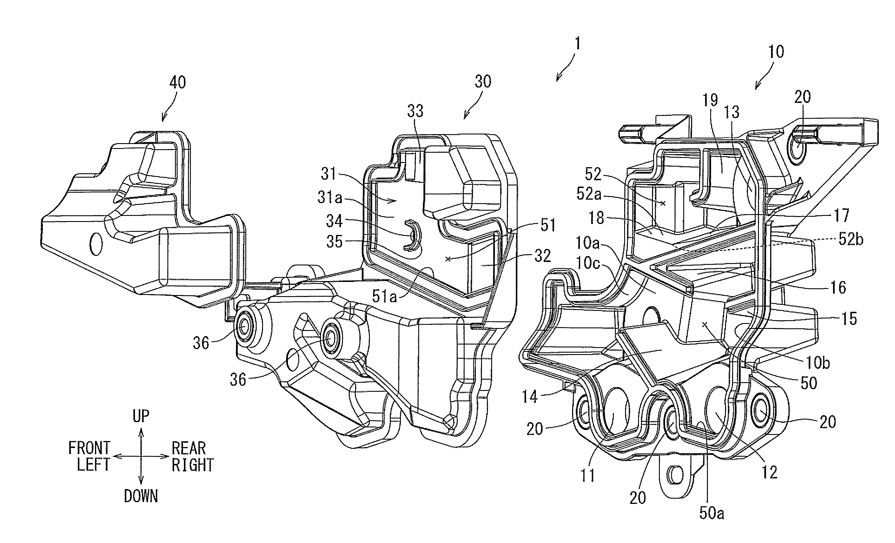
[0022] Hereinafter, an exemplary embodiment will be described with reference to FIGS. 1 to 5. As illustrated in FIGS. 1 and 2, an oil separator 1 is a labyrinth-type separator, and comprises a lower base 10, a middle base 30, and an upper base 40.
[0023] As illustrated in FIG. 2, the lower base 10 is a casing member having a recess 10a at a bottom and an opening 10b facing the middle base 30. A first flow inlet 11 and a second flow inlet 12 are formed on a lower portion of the recess 10a to allow blow-by gas (not illustrated) to flow into the oil separator 1. A flow outlet 13 is formed on an upper portion of the lower base 10 to allow the blow-by gas to flow out of the oil separator 1. A first collision wall 14, a second collision wall 15, a third collision wall 16, a fourth collision wall 17, a fifth collision wall 18, and a sixth collision wall 19 are formed within the recess 10a.
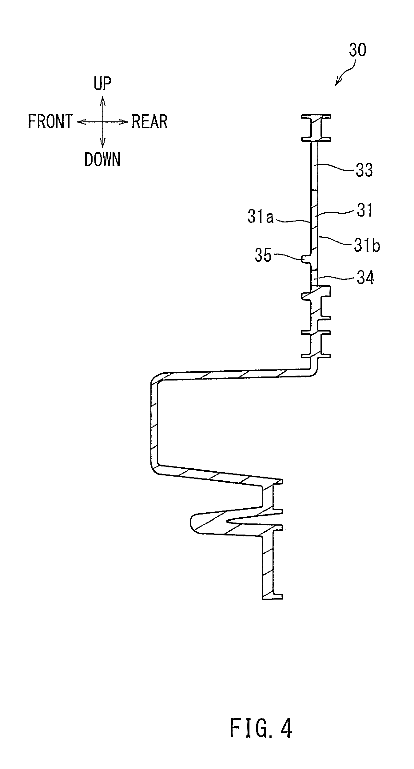
[0024] As illustrated in FIGS. 3 and 4, the middle base 30 is a panel member sized and shaped to cover the opening 10b of the lower base 10. A lower region of the middle base 30 defines a liquid oil trapping chamber 50 in cooperation with the lower base 10. The upper region of the middle base 30 defines a secondary oil-mist trapping chamber 52 in cooperation with the lower base 10. The middle base 30 defines the secondary oil-mist trapping chamber 52 and has a separation plate 31, which separates the secondary oil-mist trapping chamber 52 from a primary oil-mist trapping chamber 51. The primary oil-mist trapping chamber 51 and the secondary oil-mist trapping chamber 52 are arranged adjacent to each other, to the left and right of the separation plate 31, respectively. A first communication port 32, which allows the liquid oil trapping chamber 50 to communicate with the primary oil-mist trapping chamber 51, is formed on the right-most region of the separation plate 31. A second communication port 33, which allows the primary oil-mist trapping chamber 51 to communicate with the secondary oil-mist trapping chamber 52, is formed on the uppermost region of the separation plate 31. A return port 34 is formed at the separation plate 31. The return port 34 allows small particle size oil mist (not illustrated) trapped in the secondary oil-mist trapping chamber 52 to return to the primary oil-mist trapping chamber 51.
[0025] As illustrated in FIGS. 2 and 5, the primary oil-mist trapping chamber 51 has a bottom surface 51a. The location of the return port 34 within the chamber 51 is located at a higher level than (e.g., vertically above) the bottom surface 51a. Thus, the return port 34 is spaced vertically above and apart from the bottom surface 51a of the primary oil-mist trapping chamber 51. The secondary oil-mist trapping chamber 52 has a bottom surface 52a, and the return port 34 is positioned at substantially the same level (e.g., same vertical height) as the lowermost portion 52b of the bottom surface 52a. Unlike the conventional oil separator, the return port 34 is not located along the bottom surface 51a of the primary oil-mist trapping chamber 51. That is, the return port 34 is located only along the bottom surface 52a of the secondary oil-mist trapping chamber 52. The separation plate 31 has a wall surface 31a facing the primary oil-mist trapping chamber 51. A rib 35 is formed near the return port 34 of the wall surface 31a. In this embodiment, the rib 35 has a substantially U-shape such that it prevents the blow-by gas from flowing into the return port 34.
[0026] As illustrated in FIG. 2, the upper base 40 is a cover member sized and shaped to cover the separation plate 31 of the middle base 30. The primary oil-mist trapping chamber 51 is disposed between the upper base 40 and the separation plate 31.
[0027] As illustrated in FIG. 2, the lower base 10, the middle base 30, and the upper base 40 are assembled to each other by vibration welding, etc. The liquid oil trapping chamber 50 and the secondary oil-mist trapping chamber 52 above the liquid oil trapping chamber 50 are positioned between the lower base 10 and the middle base 30. The liquid oil trapping chamber 50 and the secondary oil-mist trapping chamber 52 are defined by partitions of the lower base 10 and the middle base 30. The primary oil-mist trapping chamber 51 is positioned between the middle base 30 and the upper base 40. The liquid oil trapping chamber 50 is a space that traps large particle size liquid oil (not illustrated) contained in the blow-by gas.
[0028] As illustrated in FIG. 2, the primary oil-mist trapping chamber 51 is located above the liquid oil trapping chamber 50. The primary oil-mist trapping chamber 51 is hence located downstream of the liquid oil trapping chamber 50 in a flow passage for the blow-by gas. The primary oil-mist trapping chamber 51 is a space that traps small particle size oil mist contained in the blow-by gas. The secondary oil-mist trapping chamber 52 is located at substantially the same vertical level (e.g., same vertical height) as the primary oil-mist trapping chamber 51, and it is adjacent to the primary oil-mist trapping chamber 51 in the horizontal left-to-right direction. The primary oil-mist trapping chamber 51 is separated from the secondary oil-mist trapping chamber 52 by the separation plate 31 of the middle base 30. The secondary oil-mist trapping chamber 52 is located downstream of the primary oil-mist trapping chamber 51 in the flow passage of the blow-by gas. The secondary oil-mist trapping chamber 52 is a space that traps small particle size oil mist contained in the blow-by gas.
[0029] The lower base 10, the middle base 30, and the upper base 40 illustrated in FIGS. 1 and 2 are different members made of rigid synthetic resin such as polypropylene. The oil separator 1 may be attached in the middle of a flow passage (not illustrated) that connects a crankcase (not illustrated) to an air-intake duct (not illustrated). For example, attaching portions 20 of the lower base 10 and attaching portions 36 of the middle base 30 are each attached to a corresponding component forming the flow passage via a metal collar (not illustrated).
[0030] As illustrated in FIGS. 2 and 5, the first flow inlet 11 and the second flow inlet 12, which are formed in the lower region of the lower base 10, each communicate with the flow passage in the crankcase. As a result, when the blow-by gas flows from the crankcase, it enters through the first flow inlet 11 and/or the second flow inlet 12 into the liquid oil trapping chamber 50. The blow-by gas, which thereby flows into the liquid oil trapping chamber 50, then collides with not only interior wall 10c of the recess 10a of the lower base 10, but also collision walls 14, 15, 16, 17 and the interior surface of the middle base 30.
[0031] As illustrated in FIG. 2, the first collision wall 14 extends upward from an intermediate region of the recess 10a between the flow inlets 11, 12 in the left-to-right direction. The collision wall 14 extends upward and obliquely above the first flow inlet 11. The second collision wall 15 extends obliquely below and inward in the horizontal direction from a right side of the interior wall 10c. The third collision wall 16 extends inward in the horizontal direction from a left side of the interior wall 10c. The third collision wall 16 extends substantially parallel to the first collision wall 14, and is positioned above the first collision wall 14. The fourth collision wall 17 is located above the third collision wall 16, and extends obliquely upward and rightward from an intermediate portion of the collision wall 16. In this manner, the collision wall 17 forms the right portion of a bottom surface of the secondary oil-mist trapping chamber 52. The collision wall 18 extends continuously leftward and upward from the collision wall 17 to form a left portion of the bottom surface of the secondary oil-mist trapping chamber 52. The collision wall 18 extends obliquely upward and leftward from the collision wall 17 to connect with a left side of the interior wall 10a. The sixth collision wall 19 extends downward from an upper wall surface of the interior wall 10a.
[0032] As illustrated in FIG. 2, the large particle size liquid oil contained in the blow-by gas collides with the interior wall 10c, the collision walls 14, 15, 16, 17, and the interior surface of the middle base 30, and thereby adheres to the corresponding surfaces. The large particle size liquid oil adhered to the interior wall 10c, collision walls 14, 15, 16, 17, and the interior surface of the middle base 30 drops under its own weight (via gravity), and accumulates on the bottom surface 50a of the liquid oil trapping chamber 50. The accumulated liquid oil then flows through the flow inlets 11, 12 and is collected. As a result, the liquid oil trapping chamber 50 serves to trap the large particle size liquid oil contained in the blow-by gas.
[0033] Referring to FIG. 2, the blow-by gas flows from the liquid oil trapping chamber 50, through the first communication port 32, and into the primary oil-mist trapping chamber 51. The blow-by gas collides with the wall surface 31a of the separation plate 31 and an interior surface of the upper base 40, etc. The small particle size oil mist contained in the blow-by gas collides with the surfaces and adheres thereto. The small particle size oil mist adhered to the wall surface 31a, etc. drops due under its own weight (via gravity), and then accumulates on the bottom surface 51a of the primary oil-mist trapping chamber 51. The small particle size oil mist subsequently returns to the liquid oil trapping chamber 50 through the first communication port 32, and then is collected together with the large particle size liquid oil. Thus, the primary oil-mist trapping chamber 51 serves to trap the small particle size oil mist contained in the blow-by gas.
[0034] Referring to FIG. 2, the blow-by gas flows from the primary oil-mist trapping chamber 51 through the second communication port 33 into the secondary oil-mist trapping chamber 52. Here, the blow-by gas collides with each of the wall surfaces in the secondary oil-mist trapping chamber 52. For example, the blow-by gas collides with the interior wall 10c of the recess 10a of the lower base 10 within the chamber 52, as well as each of the collision walls 17, 18, 19, and a back surface 31b of the separation plate 31, etc. The small particle size oil mist contained in the blow-by gas collides with the surfaces and adheres thereto. The small particle size oil mist adhered to the surfaces drops under its own weight (via gravity), and then accumulates on the bottom surface 52a of the secondary oil-mist trapping chamber 52. The small particle size oil mist returns to the primary oil-mist trapping chamber 51 through the return port 34, and is collected together with the small particle size oil mist trapped in the primary oil-mist trapping chamber 51. Thus, the secondary oil-mist trapping chamber 52 serves to trap the small particle size oil mist contained in the blow-by gas.
[0035] As illustrated in FIG. 2, a flow outlet 13 is formed on the upper right region of the lower base 10. The flow outlet 13 communicates with the communication flow passage of the air-intake duct. Therefore, the blow-by gas flown into the oil separator 1 flows from the secondary oil-mist trapping chamber 52 through the flow outlet 13 in the air-intake duct. As described above, as blow-by gas flows into the oil separator 1, large particle size liquid oil and small particle size oil mist contained in the blow-by gas are separated from the blow-by gas and discharged out of the flow inlets 11, 12. In this way, small particle size liquid oil and oil mist are prevented from flowing from the flow outlet 13 of the oil separator 1 into the air-intake duct. As a result, the blow-by gas without the liquid oil and oil mist that were initially input into the separator 1, can be returned as an output from the separator 1 to the internal combustion engine located downstream of the oil separator 1, to be combusted again in the internal combustion engine.
[0036] As described above, the oil separator 1 includes a plurality of oil-mist trapping chambers, for example, a primary oil-mist trapping chamber 51 and a secondary oil-mist trapping chamber 52. Therefore, the total length traversed by the blow-by gas passage within the oil separator 1 is relatively long. Such a long length flow passage through the oil separator offers the potential to enhance the efficiency at which the small particle size oil mist contained in the blow-by gas is trapped.
[0037] As illustrated in FIG. 2, the return port 34 allows the oil mist trapped in the secondary oil-mist trapping chamber 52 to be returned into the primary oil-mist trapping chamber 51. The first communication port 32 allows the oil mist trapped in the secondary oil-mist trapping chamber 52 and the oil mist trapped in the primary oil-mist trapping chamber 51 to be returned into the liquid oil trapping chamber 50. The flow inlets 11, 12 allow the above-described oil mist and the liquid oil trapped in the liquid oil trapping chamber 50 to be discharged. In this way, both oil mist and liquid oil can be collected. Therefore, it is possible to collect trapped oil mist with the secondary oil-mist trapping chamber 52 without providing a dedicated collecting passage, thereby reducing the amount of structural components needed. In addition, the small particle size oil mist can be efficiently trapped and the size of the oil separator 1 can be reduced.
[0038] As described above, the oil separator 1 includes a separation plate 31, an upstream oil-mist trapping chamber (primary oil-mist trapping chamber 51), and a downstream oil-mist trapping chamber (secondary oil-mist trapping chamber 52) as illustrated in FIG. 2. The trapping chambers are divided by the separation plate 31 and arranged adjacent to each other in the left-to-right direction. The upstream oil-mist trapping chamber 51 fluidly communicates with the flow inlets 11, 12 for blow-by gas via the liquid oil trapping chamber 50. The downstream oil-mist trapping chamber 52 fluidly communicates with the upstream oil-mist trapping chamber 51, as well as with the flow outlet 13 for blow-by gas. A return port 34 is formed on the separation plate 31, serving to return the oil mist trapped in the downstream oil-mist trapping chamber 52 to the upstream oil-mist trapping chamber 51. The return port 54 is located at a position vertically above the bottom surface 51a of the upstream oil-mist trapping chamber 51 and is positioned at substantially the same vertical height as the lowermost portion of the bottom surface 52a of the downstream oil-mist trapping chamber 52.
[0039] The oil contained in blow-by gas is separated from the blow-by gas by the separator 1, and gathers as droplets in both the upstream oil-mist trapping chamber 51 and the downstream oil-mist trapping chamber 52. The oil that drops and accumulates in the downstream oil-mist trapping chamber 52 passes through the return port 34 and is allowed to return to the upstream oil-mist trapping chamber 51. On the other hand, the oil that drops and accumulates in the upstream oil-mist trapping chamber 51 is not allowed to flow through the return port 34 into the downstream oil-mist trapping chamber 52. Consequently, liquid oil is not accumulated in the downstream oil-mist trapping chamber 52, and as a result, the separated liquid oil is prevented from flowing out of the downstream oil-mist trapping chamber 52 through the flow outlet 13 so as to be discharged outside of the oil separator 1. As a result, the liquid oil can be prevented from flowing to a device(s) such as an internal combustion engine positioned downstream of the oil separator 1 and from being combusted again in the internal combustion engine. In this way, the failure of a device(s) located downstream of the oil separator 1 can be prevented.
[0040] As illustrated in FIG. 2, the separation plate 31 includes the wall surface 31a facing opposite to the upstream oil-mist trapping chamber 51. The rib 35 is formed in the vicinity of the return port 34 at the wall surface 31a so that the rib 35 prevents blow-by gas from flowing into the return port 34. Therefore, blow-by gas is prevented from flowing from the upstream oil-mist trapping chamber 51 into the downstream oil-mist trapping chamber 52 through the return port 34. Thus, the blow-by gas tends not to flow through the return port 34 but through the communication port 33, which helps to flow the gas from the upstream oil-mist trapping chamber 51 into the downstream oil-mist trapping chamber 52.
[0041] As illustrated in FIGS. 2 and 3, the rib 35 has a substantial U-shaped configuration. For example, the rib 35 extends circumferentially as an arc around the return port 4. Therefore, the blow-by gas is prevented from flowing from the upstream oil-mist trapping chamber 51 through the return port 34 into the downstream oil-mist trapping chamber 52.
[0042] As illustrated in FIGS. 2 and 3, the rib 35 has a right portion standing upright between the return port 34 and the first communication port 32. Therefore, the right portion of the rib 35 prevents the blow-by gas from directly flowing from the first communication port 32 into the return port 34. The rib 35 has an upper portion extending from the right portion along the upper edge of the return port 34 and a lower portion extending from the right portion along the lower edge of the return port 34. As a result, the blow-by gas is more reliably prevented from flowing directly into the return port 34 from the first communication port 32, and rather flows around the return port 34.
[0043] The rib 35 has a substantially U-shape as illustrated in FIG. 2. Alternatively, the rib 35 may have various other shapes such as a substantially V-shape or a horseshoe shape, to deflect the gas from flowing into the return port 34. The rib has preferably a shape that obtains the same effect as that of the substantially U-shaped rib 35.
[0044] As described-above, the lower base 10, the middle base 30, and the upper base 40 are made of resin. Alternatively, the lower base 10, the middle base 30, and the upper base 40 may be made of separate metal members that are integrally connected. Such a metal oil separator generally has a higher strength and heat resistance as compared to the resin oil separator 1. As described-above, the lower base 10, the middle base 30, and the upper base 40 are made as separate members. Alternatively, two or all of these bases may be formed in one member.
[0045] As described-above, the oil separator 1 has two oil-mist trapping chambers 51, 52. Alternatively, the oil separator 1 may have more than two oil-mist trapping chambers.
[0046] The various examples described above in detail with reference to the attached drawings are intended to be representative of the present disclosure and are thus non limiting embodiments. The detailed description is intended to teach a person of skill in the art to make, use and/or practice various aspects of the present teachings and thus does not limit the scope of the disclosure in any manner. Furthermore, each of the additional features and teachings disclosed above may be applied and/or used separately or with other features and teachings in any combination thereof, to provide improved oil separators, and/or methods of making and using the same.
* * * * *
D00000
D00001
D00002
D00003
D00004
D00005
D00006
D00007
D00008
XML
uspto.report is an independent third-party trademark research tool that is not affiliated, endorsed, or sponsored by the United States Patent and Trademark Office (USPTO) or any other governmental organization. The information provided by uspto.report is based on publicly available data at the time of writing and is intended for informational purposes only.
While we strive to provide accurate and up-to-date information, we do not guarantee the accuracy, completeness, reliability, or suitability of the information displayed on this site. The use of this site is at your own risk. Any reliance you place on such information is therefore strictly at your own risk.
All official trademark data, including owner information, should be verified by visiting the official USPTO website at www.uspto.gov. This site is not intended to replace professional legal advice and should not be used as a substitute for consulting with a legal professional who is knowledgeable about trademark law.