Valve Timing Controller
IWAYA; Takashi ; et al.
U.S. patent application number 16/209124 was filed with the patent office on 2019-06-13 for valve timing controller. This patent application is currently assigned to AISIN SEIKI KABUSHIKI KAISHA. The applicant listed for this patent is AISIN SEIKI KABUSHIKI KAISHA. Invention is credited to Hiroyuki AMANO, Takashi IWAYA, Masaaki KANEKO, Toshiki SATO.
| Application Number | 20190178114 16/209124 |
| Document ID | / |
| Family ID | 66629755 |
| Filed Date | 2019-06-13 |
View All Diagrams
| United States Patent Application | 20190178114 |
| Kind Code | A1 |
| IWAYA; Takashi ; et al. | June 13, 2019 |
VALVE TIMING CONTROLLER
Abstract
A valve timing controller includes: a driving side rotation member synchronously rotating with a crankshaft of an internal combustion engine; a driven side rotation member contained in the driving side rotation member and rotating integrally with a cam shaft for opening and closing a valve coaxially with a rotating axis of the driving side rotation member; an electromagnetic valve displacing a relative rotation phase between the driving side and driven side rotation members by supplying a working fluid to advancing and retarding chambers defined between the driving side and driven side rotation members; an intermediate locking mechanism holding the relative rotation phase in an intermediate locking phase; a phase detection section detecting the relative rotation phase; and a control section controlling the electromagnetic valve based on a detection signal of the phase detection section.
| Inventors: | IWAYA; Takashi; (Obu-shi, JP) ; KANEKO; Masaaki; (Nukata-gun, JP) ; SATO; Toshiki; (Takahama-shi, JP) ; AMANO; Hiroyuki; (Kariya-shi, JP) | ||||||||||
| Applicant: |
|
||||||||||
|---|---|---|---|---|---|---|---|---|---|---|---|
| Assignee: | AISIN SEIKI KABUSHIKI
KAISHA Kariya-shi JP |
||||||||||
| Family ID: | 66629755 | ||||||||||
| Appl. No.: | 16/209124 | ||||||||||
| Filed: | December 4, 2018 |
| Current U.S. Class: | 1/1 |
| Current CPC Class: | F01L 2250/02 20130101; F01L 2800/00 20130101; F01L 2001/34433 20130101; F01L 2001/34483 20130101; F01L 2001/34456 20130101; F01L 2001/3443 20130101; F01L 2001/34469 20130101; F01L 2001/34476 20130101; F01L 1/3442 20130101; F01L 2820/041 20130101; F01L 1/356 20130101 |
| International Class: | F01L 1/356 20060101 F01L001/356; F01L 1/344 20060101 F01L001/344 |
Foreign Application Data
| Date | Code | Application Number |
|---|---|---|
| Dec 8, 2017 | JP | 2017-236335 |
Claims
1. A valve timing controller comprising: a driving side rotation member that synchronously rotates with a crankshaft of an internal combustion engine; a driven side rotation member that is contained in the driving side rotation member and rotates integrally with a cam shaft for opening and closing a valve of the internal combustion engine coaxially with a rotating axis of the driving side rotation member; an electromagnetic valve that displaces a relative rotation phase between the driving side rotation member and the driven side rotation member by supplying a working fluid to an advancing chamber and a retarding chamber defined between the driving side rotation member and the driven side rotation member; an intermediate locking mechanism that holds the relative rotation phase in an intermediate locking phase; a phase detection section that detects the relative rotation phase; and a control section that controls the electromagnetic valve based on a detection signal of the phase detection section, wherein the intermediate locking mechanism includes a first locking mechanism configured with a first lock member supported by one of the driving side rotation member and the driven side rotation member, a first lock recess portion formed on the other one of the driving side rotation member and the driven side rotation member, and a first biasing member that biases the first lock member toward the first lock recess portion, and a second locking mechanism configured with a second lock member supported by one of the driving side rotation member and the driven side rotation member, a second lock recess portion formed on the other one of the driving side rotation member and the driven side rotation member, and a second biasing member that biases the second lock member toward the second lock recess portion, the control section includes a lock releasing control section that executes a control for causing the electromagnetic valve to supply the working fluid to the one of the advancing chamber and the retarding chamber to retract the first lock member from the first lock recess portion against the biasing force of the first biasing member and displace the relative rotation phase in a first direction that becomes an advancing direction or a retarding direction from the intermediate locking phase, and after the phase detection section detects that the relative rotation phase exceeds a sequence region set from the intermediate locking phase to a predetermined phase in the first direction, executes a control for causing the electromagnetic valve to supply the working fluid to the other one of the advancing chamber and the retarding chamber to retract the second lock member from the second lock recess portion against a biasing force of the second biasing member, and the lock releasing control section includes a lock releasing determination section that determines whether or not a locked state of the intermediate locking mechanism is released based on a predetermined determination phase.
2. The valve timing controller according to claim 1, wherein the determination phase is configured with a first determination phase set in the first direction from the sequence region and a second determination phase set in a second direction opposite to the first direction from the sequence region, in the intermediate locking mechanism in the locked state, the first lock member is engaged with the first lock recess portion and the second lock member is engaged with the second lock recess portion, and the lock releasing determination section determines that the locked state is released when the relative rotation phase detected by the phase detection section is displaced in the second direction and exceeds the second determination phase after the relative rotation phase is displaced in the first direction from the intermediate locking phase and exceeds the first determination phase.
3. The valve timing controller according to claim 1, wherein the determination phase is configured with a third determination phase set in the first direction from the sequence region and a fourth determination phase positioned on a boundary on the first direction side in the sequence region, in the intermediate locking mechanism in the locked state, the first lock member is engaged with the first lock recess portion and the second lock member is engaged with the second lock recess portion, and the lock releasing determination section determines that the locked state is released when a time period until the relative rotation phase detected by the phase detection section is displaced in the second direction opposite to the first direction and exceeds the fourth determination phase after the relative rotation phase is displaced in the first direction from the intermediate locking phase and exceeds the third determination phase is longer than a first predetermined value.
4. The valve timing controller according to claim 1, wherein the determination phase is configured with a fifth determination phase set in the first direction from the sequence region, in the intermediate locking mechanism in the locked state, the first lock member is engaged with the first lock recess portion and the second lock member is engaged with the second lock recess portion, and the lock releasing determination section determines that the locked state is released when a time period during which the relative rotation phase detected by the phase detection section is displaced in the first direction from the intermediate locking phase and is within a predetermined phase range set before and after the fifth determination phase is longer than a second predetermined value.
5. The valve timing controller according to claim 1, further comprising: a drain flow passage that discharges the working fluid that acts on the second lock member to cause a lock shift operation in which the second lock member is engaged with the second lock recess portion, in a case where the relative rotation phase is set in the sequence region, wherein the determination phase is configured with a sixth determination phase set in the second direction opposite to the first direction from the sequence region and a seventh determination phase set in the first direction from the sequence region, in the intermediate locking mechanism in a state in which the locked state is released, the first lock member is not engaged with the first lock recess portion and the second lock member is not engaged with the second lock recess portion, and the lock releasing determination section determines that the state is shifted to the locked state when the relative rotation phase is not displaced in the first direction from the seventh determination phase and the control for causing the electromagnetic valve to supply the working fluid to the other one of the advancing chamber and the retarding chamber is executed in a state where the relative rotation phase detected by the phase detection section is positioned in the sequence region after being displaced in the second direction from the sixth determination phase.
6. The valve timing controller according to claim 3, wherein the first predetermined value is corrected based on a temperature of the working fluid.
7. The valve timing controller according to claim 4, wherein the second predetermined value is corrected based on a temperature of the working fluid.
Description
CROSS REFERENCE TO RELATED APPLICATIONS
[0001] This application is based on and claims priority under 35 U.S.C. .sctn. 119 to Japanese Patent Application 2017-236335, filed on Dec. 8, 2017, the entire contents of which are incorporated herein by reference.
TECHNICAL FIELD
[0002] This disclosure relates to a valve timing controller including a driving side rotation member that rotates synchronously with a crankshaft, a driven side rotation member that rotates integrally with a cam shaft for valve opening and closing, and an intermediate locking mechanism that holds a relative rotation phase between the driving side rotation member and the driven side rotation member.
BACKGROUND DISCUSSION
[0003] As a valve timing controller of the above-described configuration, JP 2013-160095A (Reference 1) discloses a technology in which an intermediate locking mechanism including a restricting mechanism and a restraining mechanism is provided, and releasing of a locked state and shift to the locked state are possible by setting a relative rotation phase by controlling an electromagnetic valve based on a detection result by a phase sensor.
[0004] According to the technology described in Reference 1, in a case where a first lock member of the restricting mechanism reaches a restriction releasable range after the electromagnetic valve is set in a retarding position and the restraining mechanism is released, a second state (state where the locked state by the restraining mechanism is released) is shifted to a first state (state where restriction of the restricting mechanism is released) by a control for switching the electromagnetic valve to the advancing position. In addition, in a case of the first state, a control aspect for shifting to the locked state by the control for switching the electromagnetic valve to the advancing position in a case where the first lock member reaches a restriction range, is illustrated.
[0005] As disclosed in Reference 1, a technology in which a shift to the locked state by the control of the relative rotation phase between a driving side rotation member and a driven side rotation member by the electromagnetic valve and a shift to the release of the locked state is possible, has high convenience since only assembly of the valve timing controller to an existing oil passage is necessary without a dedicated lock control valve for controlling the intermediate locking mechanism or a dedicated oil passage for releasing the locked state.
[0006] However, the technology described in Reference 1 executes the control for switching the electromagnetic valve to an advancing position in a case where the first lock member of the restricting mechanism has reached the restriction releasable range, but the first lock member reaches the restriction range without executing the release of the locked state in a case where a time period during which the relative rotation phase is within the restriction releasable range is short. As a result, since the electromagnetic valve is in the advancing position when the first lock member reaches the restriction range, there is a concern that the locked state is unintentionally made.
[0007] In addition, while the vehicle is running, when the electromagnetic valve is switched to the advancing position while the relative rotation phase is held within the restriction range and shifted to the locked state, it is not possible to perform a control with respect to an advancing phase. Therefore, in a situation where a position state of the first lock member is unknown, as long as the relative rotation phase is within the restriction range, since a lock releasing control, such as switching the electromagnetic valve to the advancing position after switching to the retarding position is executed, fuel efficiency or responsiveness always deteriorates.
[0008] Thus, a need exists for a valve timing controller which is not susceptible to the drawback mentioned above.
SUMMARY
[0009] A feature of a valve timing controller according to an aspect of this disclosure resides in that the valve timing controller includes: a driving side rotation member that synchronously rotates with a crankshaft of an internal combustion engine; a driven side rotation member that is contained in the driving side rotation member and rotates integrally with a cam shaft for opening and closing a valve of the internal combustion engine coaxially with a rotating axis of the driving side rotation member; an electromagnetic valve that displaces a relative rotation phase between the driving side rotation member and the driven side rotation member by supplying a working fluid to an advancing chamber and a retarding chamber defined between the driving side rotation member and the driven side rotation member; an intermediate locking mechanism that holds the relative rotation phase in an intermediate locking phase; a phase detection section that detects the relative rotation phase; and a control section that controls the electromagnetic valve based on a detection signal of the phase detection section, in which the intermediate locking mechanism includes a first locking mechanism configured with a first lock member supported by one of the driving side rotation member and the driven side rotation member, a first lock recess portion formed on the other one of the driving side rotation member and the driven side rotation member, and a first biasing member that biases the first lock member toward the first lock recess portion, and a second locking mechanism configured with a second lock member supported by one of the driving side rotation member and the driven side rotation member, a second lock recess portion formed on the other one of the driving side rotation member and the driven side rotation member, and a second biasing member that biases the second lock member toward the second lock recess portion, in which the control section includes a lock releasing control section that executes a control for causing the electromagnetic valve to supply the working fluid to the one of the advancing chamber and the retarding chamber to retract the first lock member from the first lock recess portion against the biasing force of the first biasing member and displace the relative rotation phase in a first direction that becomes an advancing direction or a retarding direction from the intermediate locking phase, and after the phase detection section detects that the relative rotation phase exceeds a sequence region set from the intermediate locking phase to a predetermined phase in the first direction, executes a control for causing the electromagnetic valve to supply the working fluid to the other one of the advancing chamber and the retarding chamber to retract the second lock member from the second lock recess portion against a biasing force of the second biasing member, and in which the lock releasing control section includes a lock releasing determination section that determines whether or not a locked state of the intermediate locking mechanism is released based on a predetermined determination phase.
BRIEF DESCRIPTION OF THE DRAWINGS
[0010] The foregoing and additional features and characteristics of this disclosure will become more apparent from the following detailed description considered with the reference to the accompanying drawings, wherein:
[0011] FIG. 1 is a configuration view of a valve timing controller;
[0012] FIG. 2 is a sectional view taken along line II-II in FIG. 1;
[0013] FIG. 3 is a block circuit diagram of a control system;
[0014] FIG. 4 is an image diagram in a locked state of a main locking mechanism;
[0015] FIG. 5 is an operation image diagram of the locking mechanism in an intermediate locking phase;
[0016] FIG. 6 is an operation image diagram of the locking mechanism in a second stop phase;
[0017] FIG. 7 is an operation image diagram of the locking mechanism in a lock release start phase;
[0018] FIG. 8 is an operation image diagram of the locking mechanism that started a retarding operation;
[0019] FIG. 9 is an operation image diagram of the locking mechanism when continuing the retarding operation;
[0020] FIG. 10 is an operation image diagram of the locking mechanism in a first stop phase;
[0021] FIG. 11 is an operation image diagram of the locking mechanism that started an advancing operation;
[0022] FIG. 12 is a timing chart illustrating phase displacement in a lock releasing control;
[0023] FIG. 13 is a flowchart of a lock releasing control according to a first example;
[0024] FIG. 14 is a timing chart illustrating phase displacement according to the first example;
[0025] FIG. 15 is a flowchart of a lock releasing control according to a second example;
[0026] FIG. 16 is a timing chart illustrating phase displacement according to the second example;
[0027] FIG. 17 is a flowchart of a lock releasing control according to a third example;
[0028] FIG. 18 is a timing chart illustrating phase displacement according to the third example;
[0029] FIG. 19 is a flowchart of a lock releasing control according to a fourth example;
[0030] FIG. 20 is a timing chart illustrating phase displacement according to the fourth example;
[0031] FIG. 21 is a flowchart of a lock releasing control according to a fifth example; and
[0032] FIG. 22 is a timing chart illustrating phase displacement according to the fifth example.
DETAILED DESCRIPTION
[0033] Hereinafter, an embodiment of the disclosure will be described based on the drawings.
Basic Configuration
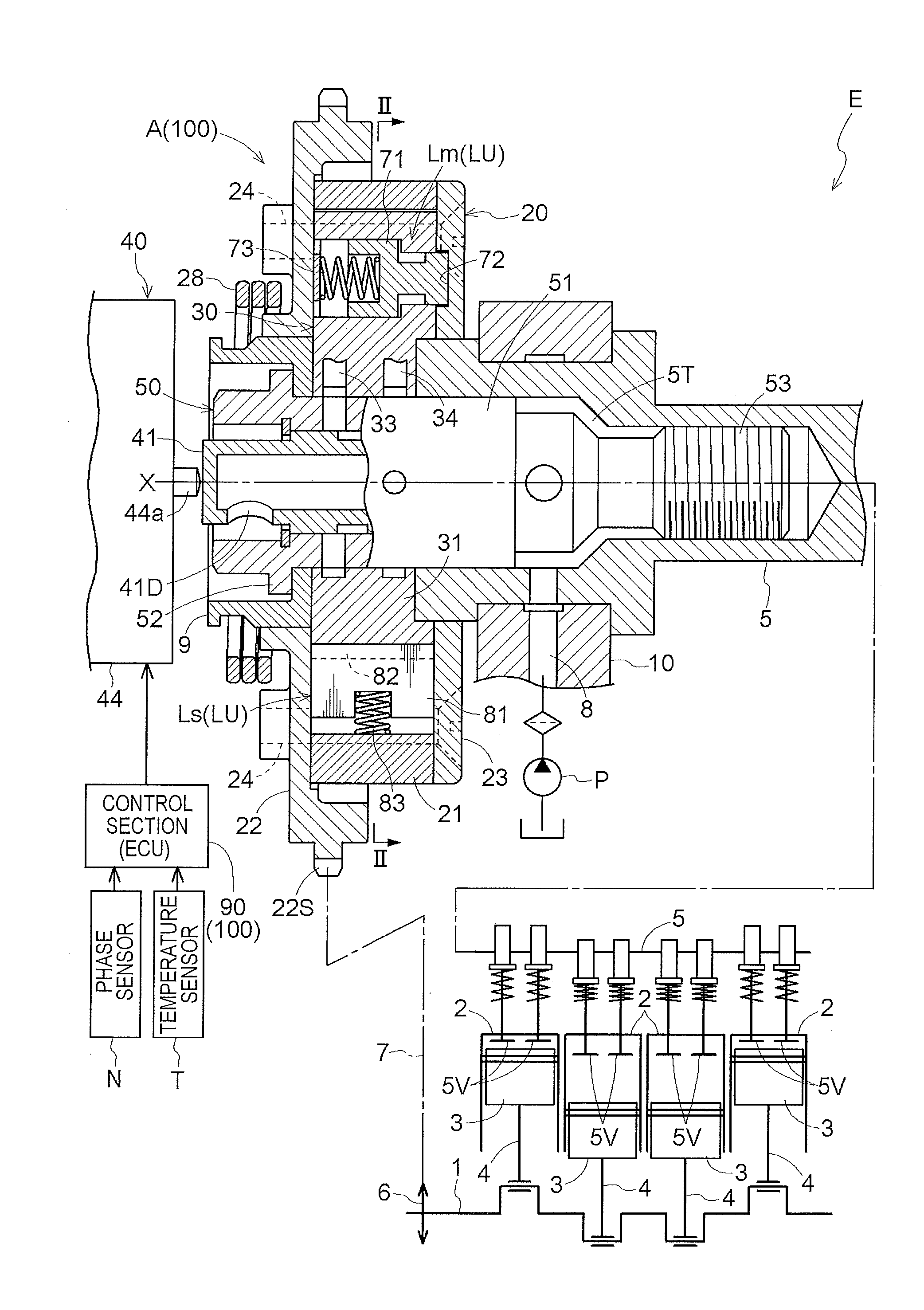
[0034] As illustrated in FIGS. 1 to 3, a valve timing control unit A including an external rotor 20 that serves as a driving side rotation member, an internal rotor 30 that serves as a driven side rotation member contained in the external rotor 20, and an electromagnetic valve 40 that controls hydraulic oil that serves as a working fluid, is configured. In addition, a valve timing controller 100 including the valve timing control unit A and a control section 90 that controls the electromagnetic valve 40, is configured.
[0035] The internal rotor 30 is connected to an intake cam shaft 5 of an engine E that serves as an internal combustion engine, and the external rotor 20 is provided so as to be rotatable relative to the internal rotor 30 coaxially with a rotating axis X of the intake cam shaft 5. Furthermore, an advancing chamber Ca and a retarding chamber Cb are formed as a fluid pressure chamber C therebetween.
[0036] The electromagnetic valve 40 supplies the hydraulic oil to one of the advancing chamber Ca and retarding chamber Cb and at the same time, displaces the relative rotation phase (hereinafter, referred to as relative rotation phase) between the external rotor 20 and the internal rotor 30 around the rotating axis X by discharging the hydraulic oil from the other one, and a control of the opening and closing timing of an intake valve 5V is realized by the displacement. In addition, by controlling the hydraulic oil by the electromagnetic valve 40, it is possible to realize the shift to the locked state in an intermediate locking phase M and the lock releasing for releasing the locked state.
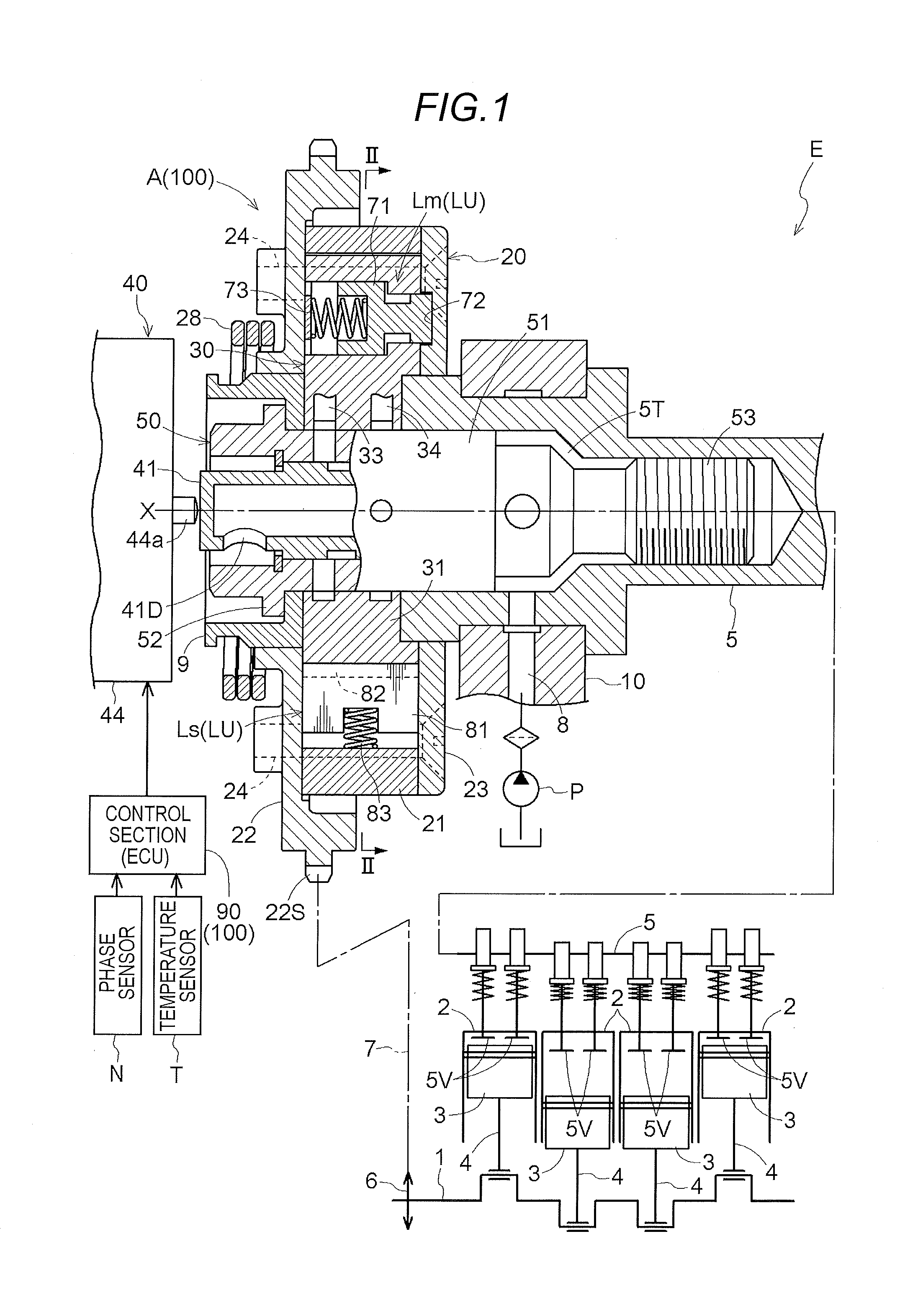
[0037] As illustrated in FIG. 2, when the engine E is in operation, the entire valve timing control unit A rotates in a driving rotational direction S. A direction in which the internal rotor 30 is displaced in a direction the same as the driving rotational direction S with respect to the external rotor 20 is referred to as an advancing direction Sa, and a direction of displacement opposite to the advancing direction Sa is referred to as a retarding direction Sb. Furthermore, the opening and closing timing of the intake valve 5V is advanced by displacement in the advancing direction Sa, and the opening and closing timing of the intake valve 5V is delayed by the displacement in the retarding direction Sb. In other words, by the displacement in the advancing direction Sa, a crank angle at the time of opening the intake valve 5V is displaced in a negative direction from a reference angle, and by the displacement in the retarding direction Sb, the crank angle at the time of opening of the intake valve 5V is displaced in a positive direction from the reference angle.
[0038] The valve timing control unit A includes an intermediate locking mechanism LU that holds the relative rotation phase in the intermediate locking phase M illustrated in FIG. 2. The intermediate locking mechanism LU is configured with a main lock portion Lm (an example of a second locking mechanism) and an auxiliary lock portion Ls (an example of a first locking mechanism), and in an intermediate locking phase M, the members reach an engaged state at the same time.
[0039] The intermediate locking phase M is a phase in which the intake valve 5V is set to the opening and closing timing appropriate for starting the engine E. Therefore, when the engine E is stopped, the control section 90 performs a control for displacing the relative rotation phase to the intermediate locking phase M before stopping the engine E and for setting the intermediate locking mechanism LU in the locked state. Meanwhile, when a feedback control is performed with respect to the relative rotation phase after the start, a control for setting the intermediate locking mechanism LU to an intermediate lock release state is performed.
Engine
[0040] The engine E (an example of an internal combustion engine) illustrated in FIG. 1 is assumed to be provided in a vehicle, such as a passenger car. The engine E includes a crankshaft 1 in a lower portion and accommodates a piston 3 in each of the four cylinder bores of an upper cylinder block 2. By connecting the piston 3 and the crankshaft 1 to each other with the connecting rod 4, the engine E is configured in a four-cylinder type. Furthermore, an upper portion of the engine E is provided with an intake cam shaft 5 for opening and closing the intake valve 5V and an exhaust cam shaft (not illustrated).
[0041] A timing chain 7 is wound around an output sprocket 6 formed in the crankshaft 1 of the engine E and a timing sprocket 22S of the external rotor 20. Furthermore, the sprocket is also provided at a front end of the exhaust cam shaft on the exhaust side, and a timing chain 7 is also wound around the sprocket.
[0042] A supply flow passage 8 through which the hydraulic oil is supplied from a hydraulic pump P driven by the engine E is formed in an engine configuration member 10 that rotatably supports the intake cam shaft 5. The hydraulic pump P supplies lubricating oil stored in the oil pan of the engine E to the electromagnetic valve 40 as the hydraulic oil via the supply flow passage 8.
[0043] Furthermore, in the embodiment, the valve timing control unit A provided in the intake cam shaft 5 is illustrated, but the valve timing control unit A may be provided in the exhaust cam shaft or may be provided in both the intake cam shaft 5 and the exhaust cam shaft.
Valve Timing Control Unit
[0044] As illustrated in FIGS. 1 and 2, the external rotor 20 includes an external rotor main body 21, a front plate 22, and a rear plate 23, which are integrated by a plurality of fastening bolts 24. The above-described timing sprocket 22S is formed at the outer periphery of the front plate 22. At the inner periphery of the external rotor main body 21, a plurality (three) of projecting portions 21T that protrude to an inner side in the radial direction is integrally formed.
[0045] The internal rotor 30 includes a cylindrical internal rotor main body 31 that is in tight contact with the projecting portion 21T of the external rotor main body 21 and a plurality (three) of vane portions 32 that protrude outward in a radial direction from the outer periphery of the internal rotor main body 31 so as to be in contact with the inner peripheral surface of the external rotor main body 21.
[0046] From the configuration, a plurality (three) of fluid pressure chambers C are formed on the outer peripheral side of the internal rotor main body 31 at an intermediate position of the projecting portions 21T adjacent to each other in the rotational direction, and the fluid pressure chambers C are divided by the vane portion 32 to define the advancing chamber Ca and the retarding chamber Cb. Furthermore, a plurality (three) of advancing flow passages 33 that communicate with the advancing chamber Ca and a plurality (three) of retarding flow passages 34 that communicate with the retarding chamber Cb are formed in the internal rotor 30.
[0047] As illustrated in FIG. 1, the front plate 22 is provided with an intermediate member 9, and a torsion spring 28 for applying a biasing force between the intermediate member 9 and the external rotor 20 is provided in the outer peripheral region of the intermediate member 9. The torsion spring 28 makes the relative rotation phase act the biasing force in the advancing direction Sa from the most retarding phase to the intermediate locking phase M, and assists the displacement in the advancing direction Sa.
Valve Timing Control Unit: Connecting Bolt
[0048] As illustrated in FIG. 1, the connecting bolt 50 includes a bolt main body 51 which is partly cylindrical, a bolt head portion 52 of the outer end portion, and a male screw portion 53 of the inner end portion.
[0049] On the inside of the intake cam shaft 5, when an in-shaft space 5T where a part of the connecting bolt 50 is tightly fitted is formed, and a female screw portion to which the male screw portion 53 of the connecting bolt 50 is screwed is formed. The in-shaft space 5T communicates with the above-described supply flow passage 8, and the hydraulic oil is supplied from the hydraulic pump P.
[0050] On the inside of the bolt main body 51, a spool chamber is formed coaxially with the rotating axis X oriented toward the male screw portion 53 from the bolt head portion 52, and a spool 41 is accommodated to be movable in a direction along the rotating axis X with respect to the spool chamber. The spool 41 supplies and discharges the hydraulic oil to and from the advancing flow passage 33 and the retarding flow passage 34 by changing the position in the direction along the rotating axis X. The outer end side (the direction of the bolt head portion 52) of the spool 41 protrudes outward by the biasing force of a spool spring (not illustrated), and a drain hole 41D for discharging the hydraulic oil is formed in a protrusion end portion thereof.
[0051] In the configuration, by screwing the connecting bolt 50 to the female screw portion of the intake cam shaft 5 and performing the connecting operation, the intermediate member 9, the internal rotor main body 31, and the intake cam shaft 5 are integrated with each other. In addition, by operating the spool 41 in the direction along the rotating axis X, it is possible to selectively supply the hydraulic oil supplied from the hydraulic pump P to the in-shaft space 5T to the advancing flow passage 33 and the retarding flow passage 34.
Electromagnetic Valve
[0052] As described above, the electromagnetic valve 40 includes the spool 41 and an electromagnetic solenoid 44. The electromagnetic solenoid 44 is provided with a plunger 44a of which a protrusion amount is controlled by the supplied electric power. In the electromagnetic valve 40 according to the embodiment, the electric power amount of the electromagnetic solenoid 44 is controlled by a known PWM control, that is, based on a duty ratio (Duty) for modulating a pulse width.
[0053] By operating the plunger 44a, the spool 41 is operated to an advancing position illustrated in FIG. 1, a neutral position where the spool 41 is accordingly pushed in only by a predetermined amount from the advancing position, and a retarding position where the spool 41 is further pushed in from the neutral position.
[0054] In addition, in the neutral position, the advancing flow passage 33 and the retarding flow passage 34 are closed, the hydraulic oil is not supplied to and discharged from the advancing chamber Ca and the retarding chamber Cb, and the relative rotation phase is maintained.
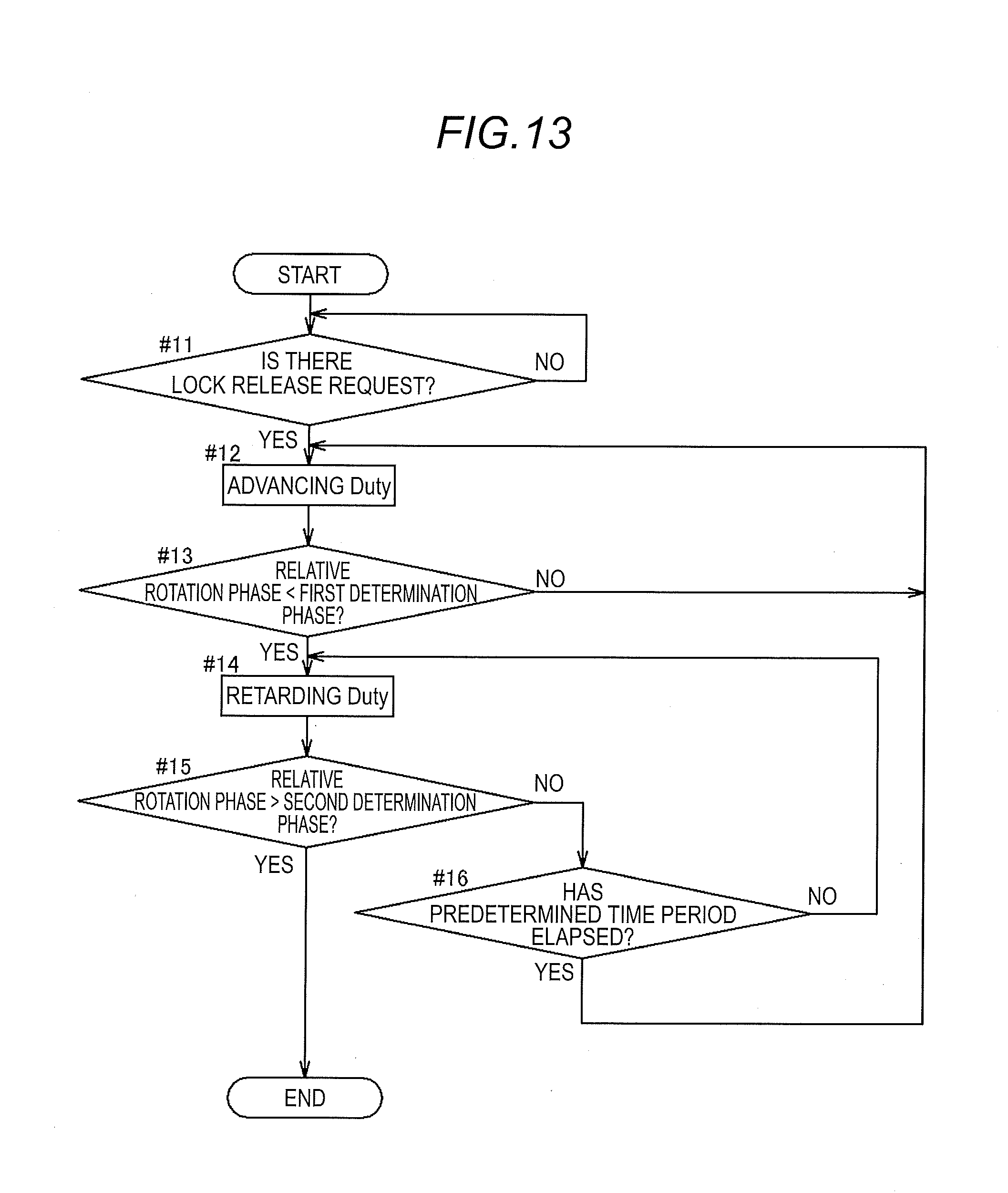
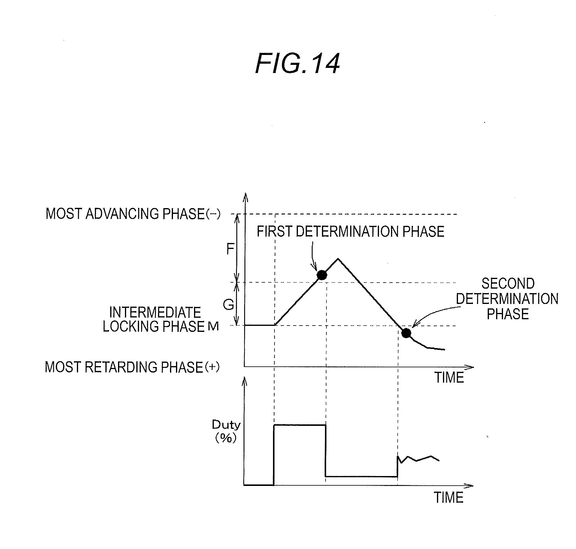
[0055] In addition, in the advancing position, the hydraulic oil from the hydraulic pump P is supplied to the advancing flow passage 33, and at the same time, the hydraulic oil from the retarding flow passage 34 is discharged via the drain hole 41D of the spool 41. Accordingly, the relative rotation phase is displaced in the advancing direction Sa.
[0056] Furthermore, in the retarding position, the hydraulic oil from the hydraulic pump P is supplied to the retarding flow passage 34, and at the same time, the hydraulic oil from the advancing flow passage 33 is discharged via the drain hole 41D of the spool 41. Accordingly, the relative rotation phase is displaced in the retarding direction Sb.
[0057] Furthermore, in the electromagnetic valve 40, by controlling the protrusion amount of the plunger 44a, it is also possible to adjust the amount of the hydraulic oil to be supplied to and discharged from the advancing chamber Ca and the retarding chamber Cb.
Intermediate Locking Mechanism: Main Lock Portion
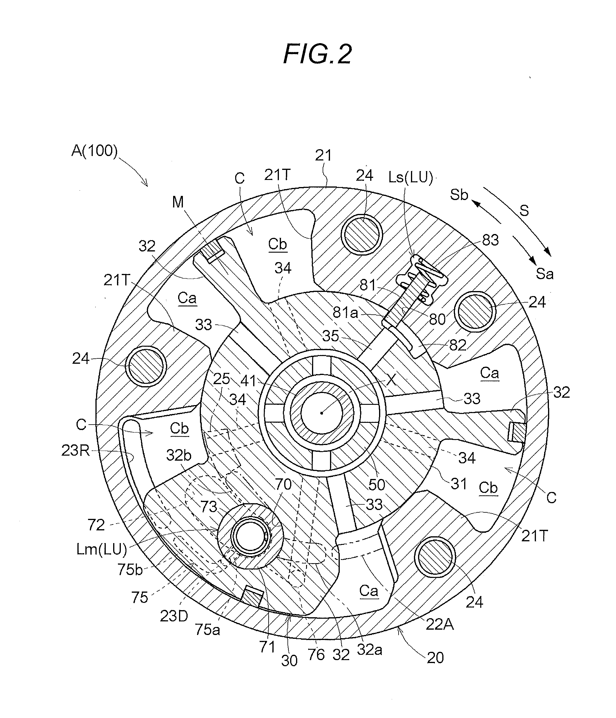
[0058] As illustrated in FIGS. 2 and 4, the main lock portion Lm (second locking mechanism) has a guide hole 70 formed in one of the plurality of vane portions 32 in a parallel posture with the rotating axis X, and at the same time, has a main lock member 71 (an example of a second lock member), a main lock recess portion 72 (an example of a second lock recess portion), and a main lock spring 73 (an example of a second biasing member).
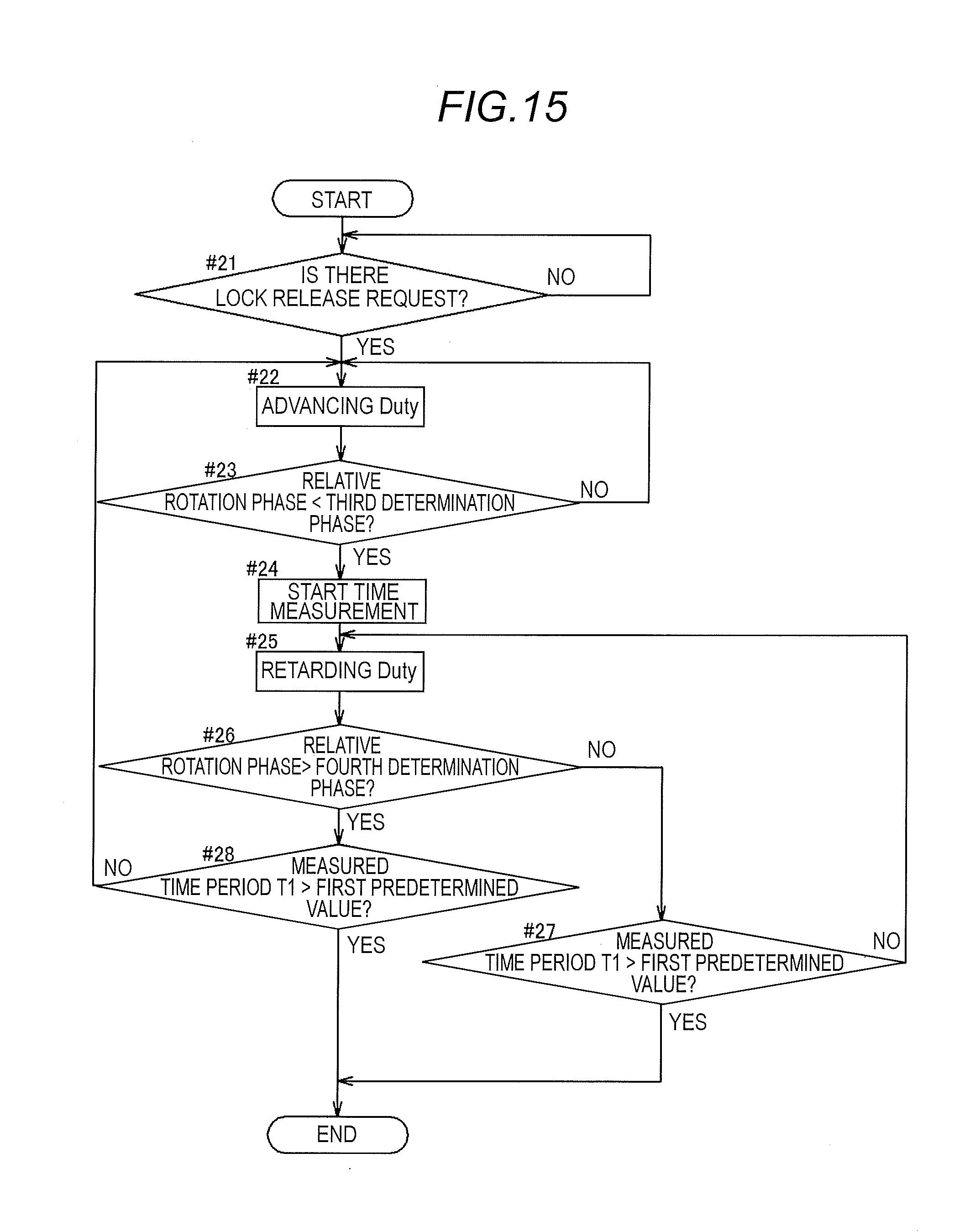
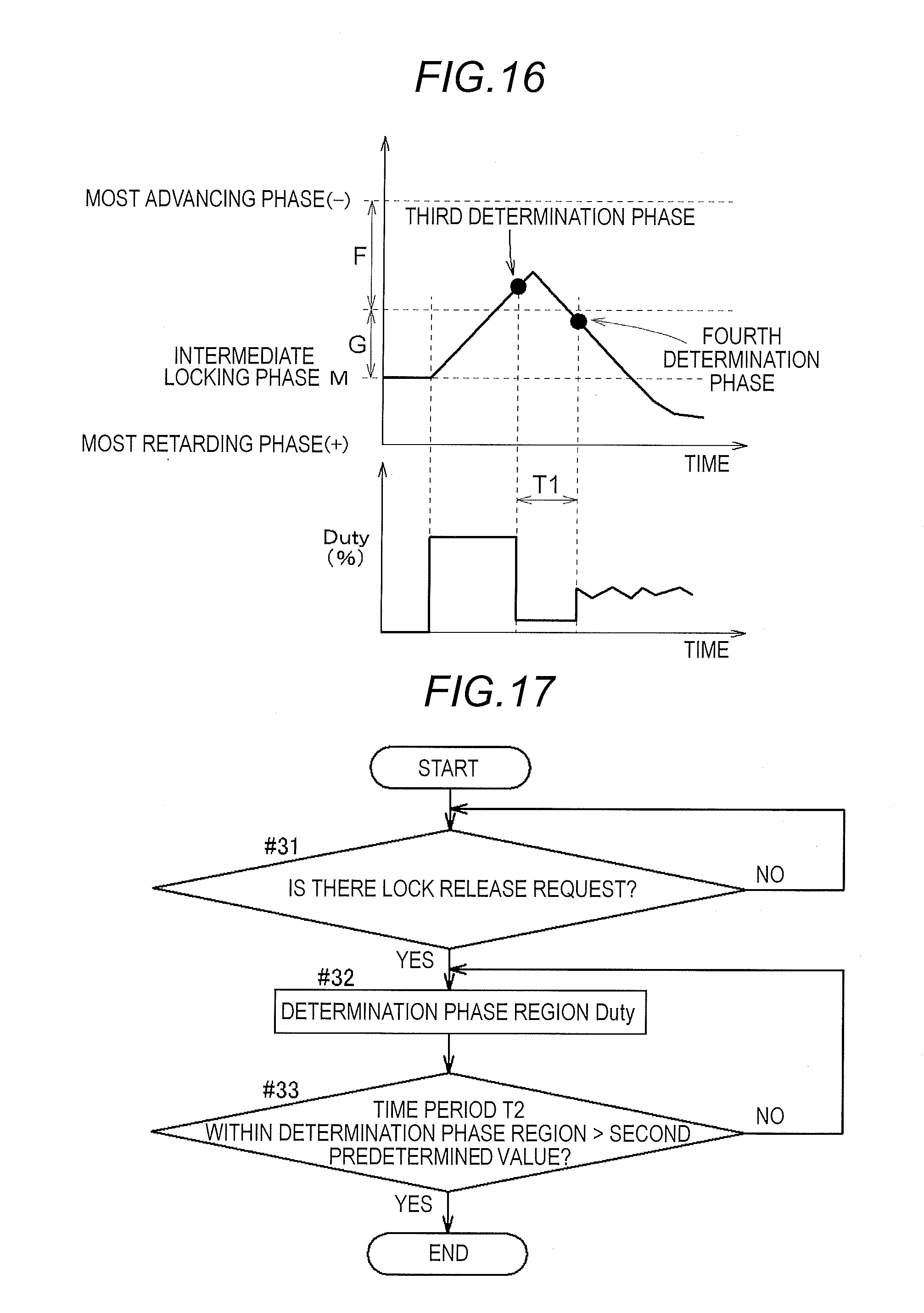
[0059] The main lock member 71 is slidably inserted into the guide hole 70. The main lock recess portion 72 is formed in a groove shape on the rear plate 23 such that an engaging portion 71b of the main lock member 71 is engaged therewith. The main lock spring 73 is configured as a compression coil type that makes the biasing force act on the main lock member 71 for engaging the engaging portion 71b with the main lock recess portion 72.
[0060] The guide hole 70 includes a large-diameter guide hole portion 70a and a small-diameter guide hole portion 70b having a smaller diameter than that of the large-diameter guide hole portion 70a. The main lock member 71 is generally columnar and includes a main body portion 71a accommodated in the large-diameter guide hole portion 70a of the guide hole 70, an engaging portion 71b accommodated in the small-diameter guide hole portion 70b with a smaller diameter than that of the main body portion 71a, and a shaft-shaped portion 71c having a smaller diameter than that of the engaging portion 71b at the intermediate position therebetween.
[0061] In the main lock member 71, a first pressure receiving surface U1 is formed at the end surface of the main body portion 71a between the main body portion 71a and the engaging portion 71b, and a second pressure receiving surface U2 is formed at the end portion on the protrusion side of the engaging portion 71b.
[0062] The main lock recess portion 72 has a width slightly wider than the diameter of the engaging portion 71b and is formed in an arc-shaped region around the rotating axis X. Accordingly, in the engaging portion 71b, in a state of being engaged with the main lock recess portion 72, the displacement of the relative rotation phase in the main restriction region is possible. In addition, the main restriction region is a region including a sequence region G (to be described later) and a lock releasing region F (a region from an advancing end to the most advancing phase in the sequence region G).
[0063] In the vane portion 32 in which the guide hole 70 is formed, a first lock releasing flow passage 75 that communicates with the small-diameter guide hole portion 70b and a second lock releasing flow passage 76 that communicates with the large-diameter guide hole portion 70a are formed.
[0064] As illustrated in FIGS. 5 to 7, the engaging portion 71b has a lock level J1 that is completely engaged with the main lock recess portion 72, a lock boundary level J2 immediately after falling out of the main lock recess portion 72 as illustrated in FIG. 11, and a lock releasing level J3 which is retracted from the main lock recess portion 72 further from the lock boundary level J2 as illustrated in FIGS. 9 and 10.
[0065] In a case where the engaging portion 71b is at the lock level J1, the first lock releasing flow passage 75 communicates with the first pressure receiving surface U1 (refer to FIG. 5). In particular, in a case where the engaging portion 71b is in a region extending from the lock level J1 to the lock boundary level J2, the second lock releasing flow passage 76 is blocked by the main body portion 71a and is in a non-communicating state with the first pressure receiving surface U1 (refer to FIGS. 5 to 8 and refer to FIG. 11).
[0066] In addition, in a case where the engaging portion 71b is in the lock releasing level J3, the first lock releasing flow passage 75 communicates with the second pressure receiving surface U2 and the second lock releasing flow passage 76 communicates with the first pressure receiving surface U1 (refer to FIGS. 9 and 10).
[0067] The first lock releasing flow passage 75 is configured to be capable of communicating with a first retarding port 75b via a first control port 75a that opens toward an inner surface of the rear plate 23 at a position retracted from the guide hole 70. The first control port 75a and the first retarding port 75b are formed in a positional relationship illustrated in FIG. 2.
[0068] The region of the rotation phase extending from the intermediate locking phase M illustrated in FIG. 5 to the phase slightly on the advancing side from the phase in FIG. 9 is referred to as the sequence region G (refer to FIG. 4). In the sequence region G, the first control port 75a communicates with a drain flow passage 23D formed on the rear plate 23. In the sequence region G, since the hydraulic oil that makes the pressure act on the first pressure receiving surface U1 is discharged from the drain flow passage 23D, the engaging portion 71b can be engaged with the main lock recess portion 72 by the biasing force of the main lock spring 73.
[0069] Furthermore, the drain flow passage 23D communicates with the external space of the rear plate 23, the sequence region G is an angle region approximately to several degrees (a crank angle of approximately 10 degrees, from the intermediate locking phase M to a predetermined phase (for example, -10 degrees) in the advancing direction Sa).
[0070] The phase obtained by displacing the relative rotation phase from the advancing end of the sequence region G in the advancing direction Sa is referred to as the lock releasing region F (refer to FIG. 4). In the lock releasing region F, since the first retarding port 75b communicates with a first retarding side groove 23R formed on the rear plate 23, the pressure of the hydraulic oil supplied to the retarding chamber Cb acts on the first pressure receiving surface U1, and the main lock member 71 operates in a direction of retracting from the main lock recess portion 72 (refer to FIG. 8).
[0071] In the second lock releasing flow passage 76, when the hydraulic oil is supplied to the retarding flow passage 34, the hydraulic oil having the same pressure as that of the retarding flow passage 34 is supplied. From the configuration, the hydraulic oil can be supplied from the second lock releasing flow passage 76 to the first pressure receiving surface U1 only in a case where the main lock member 71 is in the lock releasing level J3 illustrated in FIG. 9.
[0072] Furthermore, as a configuration for supplying the hydraulic oil to the second lock releasing flow passage 76, it is also possible to employ a flow passage configuration in which the second lock releasing flow passage 76 communicates with the retarding flow passage 34, and a flow passage configuration in which the second lock releasing flow passage 76 communicates with the retarding chamber Cb.
[0073] As illustrated in FIG. 10, a lock assist flow passage 22A is formed in a groove shape on the inner surface of the front plate 22. In a case where the relative rotation phase is displaced in the retarding direction Sb from the intermediate locking phase M, the lock assist flow passage 22A communicates with an opening part of the large-diameter guide hole portion 70a. As illustrated in FIG. 2, the lock assist flow passage 22A communicates with an assist groove 32a formed in the vane portion 32, and accordingly, a part of the hydraulic oil is supplied to the large-diameter guide hole portion 70a, but in order to make it easy to understand, in FIGS. 4 to 11 and the like, the lock assist flow passage 22A is illustrated as a configuration that can directly communicate with the large-diameter guide hole portion 70a, and the assist groove 32a is not illustrated.
[0074] Accordingly, in a case where the relative rotation phase is displaced to the retarding side from the intermediate locking phase M, a part of the hydraulic oil supplied to the advancing chamber Ca is supplied from the lock assist flow passage 22A to the large-diameter guide hole portion 70a, and assists the engagement of the main lock member 71 with the main lock recess portion 72.
[0075] Furthermore, as illustrated in FIG. 4, a communication portion 25 that communicates with the external space is formed in a hole shape with respect to the front plate 22. In a case where the relative rotation phase is in the advancing direction Sa from the intermediate locking phase M, the communication portion 25 makes the external space communicate with the large-diameter guide hole portion 70a as being communicated with the opening part of the large-diameter guide hole portion 70a. As illustrated in FIG. 2, the communication portion 25 is configured as an opening that penetrates the front plate 22, and communicates with the large-diameter guide hole portion 70a via a communication groove 32b formed in the vane portion 32, but in order to make it easy to understand, in FIGS. 4 to 11 and the like, the communication portion 25 is illustrated in the form of a groove, and the communication groove 32b is not illustrated.
[0076] By forming the communication portion 25, when the engaging portion 71b of the main lock member 71 is engaged with the main lock recess portion 72, the outside air is suctioned into the large-diameter guide hole portion 70a, reduces the influence of the negative pressure, and makes it easy to operate the main lock member 71.
Locking Mechanism: Auxiliary Lock Portion
[0077] As illustrated in FIG. 2, the auxiliary lock portion Ls (an example of the first locking mechanism) includes a support hole portion 80 formed in a posture along a radial direction around one rotating axis X among the plurality of projecting portions 21T of the external rotor main body 21, and at the same time, has an auxiliary lock member 81 (an example of a first lock member), an auxiliary lock recess portion 82 (an example of a first lock recess portion), and an auxiliary lock spring 83 (an example of a first biasing member).
[0078] The auxiliary lock member 81 is slidably inserted into the support hole portion 80. The auxiliary lock recess portion 82 is formed in a recessed shape along a peripheral direction on the outer periphery of the internal rotor main body 31 such that a restriction end portion 81a of the auxiliary lock member 81 is engaged therewith. The auxiliary lock spring 83 is configured as a compression coil type that makes the biasing force for engaging the restriction end portion 81a with the auxiliary lock recess portion 82 act.
[0079] Accordingly, in a state where the restriction end portion 81a is engaged with the auxiliary lock recess portion 82, it becomes possible to displace the relative rotation phase in the auxiliary restriction region (the most retarding phase from the intermediate locking phase M) along a direction in which the auxiliary lock recess portion 82 is formed. An auxiliary lock releasing flow passage 35 communicates with the auxiliary lock recess portion 82, and the hydraulic oil from the advancing flow passage 33 is supplied to the auxiliary lock recess portion 82.
[0080] As illustrated in FIG. 5, the main lock member 71 of the main lock portion Lm is engaged with the main lock recess portion 72, and abuts against the end portion of the main restriction region of the main lock recess portion 72, and as the auxiliary lock member 81 of the auxiliary lock portion Ls abuts against the end portion of the auxiliary restricting region of the auxiliary lock recess portion 82, the relative rotation phase is locked to the intermediate locking phase M.
Phase Sensor
[0081] The valve timing controller 100 includes a phase sensor N (an example of the phase detection section) for detecting the relative rotation phase between the external rotor 20 and the internal rotor 30 (refer to FIG. 1). As illustrated in FIG. 3, the phase sensor N includes a first sensor 11 for detecting rotation of the crankshaft 1 and a second sensor 12 for detecting rotation of the intake cam shaft 5.
[0082] The phase sensor N is also used as a cylinder determination sensor for determining a firing order of the four cylinders at the time of the start of the engine E. In addition, the phase sensor N is used as a rotation angle sensor NA (an example of a rotation angle detection section) that detects the rotation angle of the intake cam shaft 5, and the second sensor 12 is also used as a rotation speed sensor that detects a rotation speed of the crankshaft 1.
[0083] The first sensor 11 includes a first disk 11A rotated integrally with the crankshaft 1 and made of a magnetic body, such as an iron material, and a pickup type first proximity sensor portion 11B that detects multiple first tooth portions 11At formed at the outer periphery of the first disk 11A. A configuration in which one cutout portion 11An in which the first tooth portion 11At does not exist at the outer periphery of the first disk 11A is formed, and a count value (integrated value) can be acquired by counting the number of the first tooth portions 11At with reference to the cutout portion 11An ("0"), is employed.
[0084] The second sensor 12 includes a second disk 12A rotated integrally with the intake cam shaft 5 (internal rotor 30) and made of a magnetic body, such as an iron material, and a pickup type second proximity sensor portion 12B that detects a plurality (four) of second tooth portions 12At formed at the outer periphery of the second disk 12A. Furthermore, each peripheral length of the plurality of second tooth portions 12At is made different in order to make it possible to determine a cylinder.
[0085] In the configuration, in a case where the relative rotation phase of the valve timing control unit A is at the reference phase, when the intake cam shaft 5 rotates, a count value (integrated value based on a cutout portion 11An) of the first sensor 11 at the timing of detecting (detecting a down edge) an edge part of four second tooth portions 12At by the second proximity sensor portion 12B matches a value that corresponds to a reference posture.
[0086] Accordingly, in a case of determining the relative rotation phase by a phase determination section 91 of the control section 90, it is identified which of the second tooth portions 12At is the four second tooth portions 12At detected by the second proximity sensor portion 12B. In addition to the identification, it becomes possible to acquire the relative rotation phase from the count value (integrated value based on the cutout portion 11An) of the detection signal of the first proximity sensor portion 11B at the timing of detecting the edge of the second tooth portion 12At, and a difference (offset value) between the reference value (reference value that corresponds to four second tooth portions 12At) and the count value.
[0087] Furthermore, since the peripheral lengths of the four second tooth portions 12At are different from each other, the count value of the first sensor 11 in a case where the second proximity sensor portion 12B is in the region where the second tooth portion 12At is detected is different, and the four second tooth portions 12At are identified from the count value.
Phase Sensor: Function as Rotation Angle Sensor
[0088] Further, in order to function as the rotation angle sensor NA, the end portion on the down edge side of the second tooth portion 12At of the second disk 12A is formed at a position equally divided by an angle around the rotating axis X into four (divided at 90 degrees).
[0089] Accordingly, in a case where the intake cam shaft 5 reaches the reference rotation angle, the count value (the integrated value with reference to the cutout portion 11An) of the detection signal of the first proximity sensor portion 11B becomes a value determined corresponding to the four second tooth portions 12At. Therefore, in a case of determining the rotation angle of the intake cam shaft 5 at a predetermined timing, the count value of the detection signal of the first proximity sensor portion 11B is acquired, which of the second tooth portions 12At is the count value is identified, and it becomes possible to determine the rotation angle from the difference (either positive or negative value depending on the reference value) between the reference count value and the acquired count value.
[0090] Furthermore, by counting the detection signal of the first proximity sensor portion 11B of the first sensor 11 within a unit time, it is possible to acquire the rotational speed of the crankshaft 1.
Control Section
[0091] As illustrated in FIG. 3, the control section 90 also has a function of an engine control unit (ECU) for controlling the engine E, the detection signals from the phase sensor N that detects the relative rotation phase and a temperature sensor T that detects the temperature (basically, water temperature of the cooling water) of the engine E are input, and a control signal is output to the electromagnetic solenoid 44 of the electromagnetic valve 40.
[0092] In addition, the control section 90 includes the phase determination section 91, a rotation angle determination section 92, a phase control section 93, an initial phase setting section 94, a lock shift control section 95, a lock releasing control section 96, a correction processing section 97, and a table 98.
[0093] The phase determination section 91 determines the relative rotation phase based on the detection result of the phase sensor N as described above. By making the phase sensor N function as the rotation angle sensor NA as described above, the rotation angle determination section 92 determines the rotation angle of the intake cam shaft 5 from the detection result of the second sensor 12. The phase control section 93 sets the relative rotation phase to the target phase.
[0094] When executing the control to shift the intermediate locking mechanism LU to the locked state by the lock shift control section 95, the initial phase setting section 94 shifts the relative rotation phase to a preset phase (lock shift start phase K or first stop phase Q1) (FIG. 8 or 10). The lock shift control section 95 performs a control for shifting the intermediate locking mechanism LU to the locked state. The lock releasing control section 96 performs a control for releasing the locked state of the intermediate locking mechanism LU. Although the details will be described later, the lock releasing control section 96 in the embodiment includes a lock releasing determination section 96a for determining whether or not the intermediate locking mechanism LU releases the locked state based on a predetermined determination phase.
[0095] The table 98 stores various parameters (a first determination phase to a seventh determination phase, a re-determination phase region, a first predetermined value to a third predetermined value to be described later) at the time of shifting the intermediate locking mechanism LU to the lock releasing in the lock releasing control section 96, therein. The correction processing section 97 performs correction processing with respect to the various parameters stored in the table 98 based on the rotational speed of the engine E, the oil temperature, and the like.
[0096] Furthermore, the phase determination section 91, the rotation angle determination section 92, the phase control section 93, the initial phase setting section 94, the lock shift control section 95, the lock releasing control section 96, and the correction processing section 97 are configured with software, but may be configured by a combination of hardware, such as logic, and software.
Lock Releasing
[0097] The operation of releasing the locked state of the intermediate locking mechanism LU will be described with reference to FIGS. 5 to 12. In addition, in the following description, the control for supplying the hydraulic oil to a flow passage system (advancing flow passage 33, advancing chamber Ca, and the like) that displaces the relative rotation phase in the advancing direction Sa is referred to as "advancing operation", and conversely, the control for supplying the hydraulic oil to a flow passage system (retarding flow passage 34, retarding chamber Cb, and the like) that displaces the relative rotation phase in the retarding direction Sb is referred to as "retarding operation".
[0098] In the embodiment, in a case of releasing the locked state of the intermediate locking mechanism LU, the control is performed in order in which the lock releasing control section 96 is operated in the retarding direction Sb after displacing the relative rotation phase in the advancing direction Sa. The details thereof will be described later.
[0099] At the start of the engine E, as illustrated in FIG. 5, the relative rotation phase is in the locked state restrained to the intermediate locking phase M (V in FIG. 12). Next, after the start of the engine E, at the time when reaching the timing of executing the phase control of the relative rotation phase, the lock releasing control section 96 executes the advancing operation. In the advancing operation, the hydraulic oil is supplied from the advancing flow passage 33 to the advancing chamber Ca, and a part of the hydraulic oil is supplied to the auxiliary lock releasing flow passage 35.
[0100] According to the supply, in the auxiliary lock portion Ls, as illustrated in FIG. 6, the restriction end portion 81a of the auxiliary lock member 81 is retracted from the auxiliary lock recess portion 82, the displacement is performed in a state where the engaging portion 71b is engaged with the main lock recess portion 72 in the main lock portion Lm, and any phase in the region from the intermediate locking phase M to the most advancing angle phase is set.
[0101] In other words, the lock releasing control section 96 executes the advancing operation first, and accordingly, the locked state of the auxiliary lock portion Ls is released (VI in FIG. 12). In addition, in a case where the relative rotation phase exceeds the sequence region G and reaches the lock releasing region F illustrated in FIG. 7, the advancing operation is stopped (VII in FIG. 12). In this state, the lock releasing control section 96 stops the advancing operation and executes the control for supplying the hydraulic oil to the retarding chamber Cb, but since the retarding chamber Cb is not filled with the hydraulic oil, and even in a case where the lock releasing region F has been reached and the lock releasing control section 96 stops the advancing operation, the relative rotation phase is further displaced in the advancing direction Sa (VIII in FIG. 12).
[0102] Thereafter, since the hydraulic oil is supplied to the retarding flow passage 34 by executing the control for supplying the hydraulic oil to the retarding chamber Cb by the lock releasing control section 96, the pressure of the hydraulic oil acts on the first pressure receiving surface U1 from the first lock releasing flow passage 75 via the first retarding side groove 23R. Accordingly, the main lock member 71 starts an operation in a lock releasing direction as illustrated in FIG. 8. Thereafter, the relative rotation phase is displaced in the retarding direction Sb as the main lock member 71 moves in the lock releasing direction and reaches the lock releasing level J3 as illustrated in FIG. 9 (IX in FIG. 12). In the lock releasing level J3, since the lock boundary level J2 has been exceeded, it becomes possible to supply the hydraulic oil from the second lock releasing flow passage 76 to the first pressure receiving surface U1. By continuing the displacement in the retarding direction Sb, the relative rotation phase exceeds the intermediate locking phase M in a state where the main lock member 71 is maintained in the lock releasing level J3, and at this time, in the auxiliary lock portion Ls, since the hydraulic oil of the auxiliary lock recess portion 82 is discharged as the hydraulic oil is discharged from the advancing chamber Ca, the auxiliary lock member 81 is engaged with the auxiliary lock recess portion 82 (X in FIGS. 10 and 12). The displacement in the retarding direction is performed in a range (intermediate locking phase M to most retarding phase) in which the auxiliary lock member 81 is displaced in a state of being engaged with the auxiliary lock recess portion 82.
[0103] In this manner, in a case where the lock releasing of the intermediate locking mechanism LU is appropriately executed, as illustrated by the solid line in FIG. 12, the relative rotation phase exceeds the retarding end of the sequence region G, that is, the intermediate locking phase M. However, in a case where the time period after the relative rotation phase exceeds the advancing end of the sequence region G until reaching a state (state in FIG. 9) where the main lock member 71 reaches the lock releasing level J3 from a state (state in FIG. 7) where the first retarding side groove 23R and the first lock releasing flow passage 75 communicate with each other is short, or in a case where the hydraulic oil pressure that acts on the first pressure receiving surface U1 is low, the main lock member 71 cannot reach the lock boundary level J2, and as illustrated by one-dot chain line in FIG. 12, there is a concern that the lock releasing cannot be executed.
[0104] In addition, even when the lock releasing of the intermediate locking mechanism LU is appropriately executed, the advancing operation is performed from the state illustrated in FIG. 10 to the state illustrated in FIG. 11, and there is a case where the relative rotation phase is held in a second stop phase Q2 included in the sequence region G (X to XI in FIG. 12). As described above, in the sequence region G, since the hydraulic oil that makes the pressure act on the first pressure receiving surface U1 is discharged from the drain flow passage 23D, in a case where the relative rotation phase is held in the second stop phase Q2, the main lock member 71 is engaged with the main lock recess portion 72 by the biasing force of the main lock spring 73 (refer to FIG. 6). At this time, as illustrated by the broken line in FIG. 12, in a case where the retarding operation is executed from the second stop phase Q2, since the hydraulic oil is not supplied to the auxiliary lock releasing flow passage 35, the auxiliary lock member 81 of the auxiliary lock portion Ls is engaged with the auxiliary lock recess portion 82, and the locked state in the intermediate locking phase M is made. Therefore, in a case where the retarding operation is executed when the relative rotation phase is in the sequence region G, as illustrated by the solid line in FIG. 12, the lock releasing control section 96 must execute the lock releasing control again. As a result, deterioration of fuel efficiency or deterioration of responsiveness of the valve timing controller 100 is caused.
[0105] Here, a control method that can reliably release the locked state in a case where there is a lock release request after the start of the engine E, or a control method that can remove inconvenience that the lock releasing control is necessarily performed in a case where the relative rotation phase is held in the sequence region G while the vehicle is running after the locked state is released, is required. Hereinafter, the specific contents in the lock releasing determination section 96a of the lock releasing control section 96 used to realize the above-described control methods will be described below.
Control Method
First Example
[0106] A first example of a determination procedure in the lock releasing determination section 96a of the lock releasing control section 96 will be described with reference to FIGS. 13 to 14. The determination phase used in the lock releasing determination section 96a in the example is configured with a first determination phase (for example, a crank angle of -12 degrees from the intermediate locking phase M) set in the advancing direction Sa (an example of the first direction) from the sequence region G, and a second determination phase (for example, a crank angle of +2 degrees from the intermediate locking phase M) set in the retarding direction Sb (an example in the second direction opposite to the first direction) from the sequence region G.
[0107] At the start of the engine E, the relative rotation phase is held in the intermediate locking phase M, and the lock releasing determination section 96a determines whether or not there is the lock release request, such as stepping of a driver on an accelerator pedal (#11 in FIG. 13). In a case where there is the lock release request (determination of Yes in #11 in FIG. 13), the lock releasing control section 96 supplies the electric power to the electromagnetic valve 40 at a duty ratio at which an advancing operation is performed (refer to #12 in FIG. 13 and FIG. 14). As a result, the locked state of the auxiliary lock portion Ls is released, the displacement is performed in a state where the engaging portion 71b is engaged with the main lock recess portion 72 in the main lock portion Lm, and accordingly, the relative rotation phase is displaced in the advancing direction Sa from the intermediate locking phase M (state in FIGS. 5 to 7).
[0108] Next, the lock releasing determination section 96a determines whether or not the relative rotation phase detected by the phase sensor N is smaller than the first determination phase (#13 in FIG. 13). In other words, it is determined whether or not the relative rotation phase detected by the phase sensor N has exceeded the first determination phase and further displaced to the advancing side. In a case where the relative rotation phase is smaller than the first determination phase (determination of Yes in #13 in FIG. 13), the lock releasing control section 96 supplies the electric power to the electromagnetic valve 40 at a duty ratio at which a retarding operation is performed (refer to #14 in FIG. 13 and FIG. 14). At this time, even in a case where the lock releasing control section 96 reaches the first determination phase of the lock release region F and the advancing operation is stopped due to the fact that the retarding chamber Cb is not filled with the hydraulic oil or the response delay of the electromagnetic valve 40, after the relative rotation phase is temporarily displaced to the advancing side, the relative rotation phase is displaced to the retarding side (refer to FIG. 14). At this time, the hydraulic oil pressure acts on the first pressure receiving surface U1 from the first lock releasing flow passage 75 via the first retarding side groove 23R, and the main lock member 71 starts the operation in the lock releasing direction (refer to FIGS. 8 to 9).
[0109] Next, the lock releasing determination section 96a determines whether or not the relative rotation phase detected by the phase sensor N is greater than the second determination phase (#15 in FIG. 13). In other words, it is determined whether or not the relative rotation phase detected by the phase sensor N has exceeded the second determination phase and further displaced to the retarding side. In a case where the relative rotation phase is equal to or less than the second determination phase (determination of No in #15 in FIG. 13), the lock releasing determination section 96a determines whether or not a predetermined time period has elapsed after the lock release request appears (or after the relative rotation phase exceeds the first determination phase) (#16 in FIG. 13). As a result of the determination of #16, in a case where the predetermined time period has not elapsed, the retarding operation is continued, and in a case where the predetermined time period has elapsed, the main lock member 71 has not reached the lock boundary level J2, that is, it is determined that the locked state of the intermediate locking mechanism LU is not released and the lock release sequence is re-executed returning to #12.
[0110] Meanwhile, as a result of the determination in #15, in a case where the relative rotation phase is greater than the second determination phase (determination of Yes in #15 in FIG. 13), it is determined that the locked state of the intermediate locking mechanism LU is released. In this state, after the main lock member 71 starts the operation in the lock releasing direction, the lock releasing level J3 has been reached (refer to FIGS. 9 to 10). As the locked state of the intermediate locking mechanism LU is released, the phase control section 93 executes the feedback control such that the relative rotation phase is the target phase (refer to FIG. 14). Accordingly, it is possible to reliably execute the lock releasing of the intermediate locking mechanism LU at the time of the start of the engine E.
Second Example
[0111] A second example of the determination procedure in the lock releasing determination section 96a of the lock releasing control section 96 will be described with reference to FIGS. 15 to 16. The determination phase used in the lock releasing determination section 96a in the example is configured with a third determination phase (for example, a crank angle of -13 degrees from the intermediate locking phase M) set in the advancing direction Sa from the sequence region G, and a fourth determination phase (for example, a crank angle of -9 degrees from the intermediate locking phase M) positioned in the vicinity of the boundary on the advancing direction Sa side in the sequence region G.
[0112] At the start of the engine E, the relative rotation phase is held in the intermediate locking phase M, and the lock releasing determination section 96a determines whether or not there is the lock release request, such as stepping of the driver on the accelerator pedal (#21 in FIG. 15). In a case where there is the lock release request (determination of Yes in #21 in FIG. 15), the lock releasing control section 96 supplies the electric power to the electromagnetic valve 40 at a duty ratio at which an advancing operation is performed (refer to #22 in FIG. 15 and FIG. 16). As a result, the locked state of the auxiliary lock portion Ls is released, the displacement is performed in a state where the engaging portion 71b is engaged with the main lock recess portion 72 in the main lock portion Lm, and accordingly, the relative rotation phase is displaced in the advancing direction Sa (state in FIGS. 5 to 7) from the intermediate locking phase M.
[0113] Next, the lock releasing determination section 96a determines whether or not the relative rotation phase detected by the phase sensor N is smaller than the third determination phase (#23 in FIG. 15). In other words, it is determined whether or not the relative rotation phase detected by the phase sensor N has exceeded the third determination phase and further displaced to the advancing side. In a case where the relative rotation phase is smaller than the third determination phase (determination of Yes in #23 in FIG. 15), the lock releasing control section 96 starts time measurement, and at the same time, supplies the electric power to the electromagnetic valve 40 at a duty ratio at which the retarding operation is performed (refer to #24 and #25 in FIG. 15 and FIG. 16). At this time, even in a case where the lock releasing control section 96 reaches the third determination phase of the lock release region F and the advancing operation is stopped due to the fact that the retarding chamber Cb is not filled with the hydraulic oil or the response delay of the electromagnetic valve 40, after the relative rotation phase is temporarily displaced to the advancing side, the relative rotation phase is displaced to the retarding side (refer to FIG. 16). In addition, the hydraulic oil pressure acts on the first pressure receiving surface U1 from the first lock releasing flow passage 75 via the first retarding side groove 23R, and the main lock member 71 starts the operation in the lock releasing direction (refer to FIGS. 8 to 9).
[0114] Next, the lock releasing determination section 96a determines whether or not the relative rotation phase detected by the phase sensor N is greater than the fourth determination phase (#26 in FIG. 15). In other words, it is determined whether or not the relative rotation phase detected by the phase sensor N has exceeded the fourth determination phase and further displaced to the retarding side (refer to FIG. 16). In a case where the relative rotation phase is equal to or less than the fourth determination phase (determination of No in #26 in FIG. 15), the lock releasing determination section 96a determines whether or not a measured time period T1 after the relative rotation phase exceeds the third determination phase exceeds a first predetermined value (for example, 1 second) (#27 in FIG. 15). As a result of the determination of #27, in a case where the measured time period T1 does not exceed the first predetermined value, the lock releasing control section 96 continues the retarding operation (determination of No in #27 in FIG. 15). Meanwhile, as a result of the determination in #27, in a case where the measured time period T1 exceeds the first predetermined value (determination of Yes in #27 in FIG. 15), it is determined that the locked state of the intermediate locking mechanism LU is released. In the state, it is estimated that the locked state of the intermediate locking mechanism LU has been released since the retarding operation time period after the main lock member 71 starts the operation in the lock releasing direction until reaching the lock releasing level J3 is sufficiently ensured. As the locked state of the intermediate locking mechanism LU is released, the phase control section 93 executes the feedback control such that the relative rotation phase is the target phase (refer to FIG. 16).
[0115] Meanwhile, as a result of the determination of #26, in a case where the relative rotation phase is greater than the fourth determination phase (determination of Yes in #26 in FIG. 15), the lock releasing determination section 96a determines whether or not the measured time period T1 after the relative rotation phase exceeds the third determination phase exceeds a first predetermined value (#28 in FIG. 15). As a result of the determination in #28, in a case where the measured time period T1 exceeds the first predetermined value (determination of Yes in #28 in FIG. 15), it is determined that the locked state of the intermediate locking mechanism LU is released similar to the determination result of Yes in #27. As a result of the determination of #28, in a case where the measured time period T1 does not exceed the first predetermined value (determination of No in #28 in FIG. 15), the retarding operation time period is not sufficiently ensured. Therefore, the lock releasing determination section 96a determines that the main lock member 71 has not reached the lock boundary level J2, that is, determines that the locked state of the intermediate locking mechanism LU is not released, the lock releasing control section 96a re-executes the lock release sequence returning to #22. Accordingly, it is possible to reliably execute the lock releasing of the intermediate locking mechanism LU at the time of the start of the engine E.
Third Example
[0116] A third example of the determination procedure in the lock releasing determination section 96a of the lock releasing control section 96 will be described with reference to FIGS. 17 to 18. The determination phase used in the lock releasing determination section 96a in the example is configured with a fifth determination phase (for example, a crank angle of -15 degrees from the intermediate locking phase M) set in the advancing direction Sa from the sequence region G, and includes a determination phase region (an example of the predetermined phase range) before and after (for example, a crank angle of .+-.3 degrees) the fifth determination phase.
[0117] At the start of the engine E, the relative rotation phase is held in the intermediate locking phase M, and the lock releasing determination section 96a determines whether or not there is the lock release request, such as stepping of the driver on the accelerator pedal (#31 in FIG. 17). In a case where there is the lock release request (determination of Yes in #31 in FIG. 17), the lock releasing control section 96 supplies the electric power to the electromagnetic valve 40 at a duty ratio at which the relative rotation phase becomes the phase within the determination phase region (refer to #32 in FIG. 17 and FIG. 18). At the duty ratio at which the relative rotation phase becomes a phase within the determination phase region, the feedback control is performed such that the relative rotation phase detected by the phase sensor N is the phase within the determination phase region after the lock releasing control section 96 is set to the duty ratio at which the advancing operation is temporarily performed in a case where there is the lock release request. In other words, as a result of setting the duty ratio at which the advancing operation is temporarily performed, the locked state of the auxiliary lock portion Ls is released, the displacement is performed in a state where the engaging portion 71b is engaged with the main lock recess portion 72 in the main lock portion Lm, and accordingly, the relative rotation phase is displaced in the advancing direction Sa from the intermediate locking phase M (state in FIGS. 5 to 7). After this, as a result of performing the feedback control such that the relative rotation phase is the phase within the determination phase region, the hydraulic oil pressure acts on the first pressure receiving surface U1 from the first lock releasing flow passage 75 via the first retarding side groove 23R, and the main lock member 71 starts the operation in the lock releasing direction (refer to FIGS. 8 to 9).
[0118] Next, the lock releasing determination section 96a determines whether or not a time period T2 during which the relative rotation phase detected by the phase sensor N is positioned within the determination phase region is longer than the second predetermined value (for example, 2 seconds) (#33 in FIG. 17). In a case where the time period T2 during which the relative rotation phase is positioned within the determination phase region is longer than the second predetermined value (determination of Yes in #33 in FIG. 17), it is determined that the locked state of the intermediate locking mechanism LU is released. In the state, it is estimated that the locked state of the intermediate locking mechanism LU has been released since the retarding operation time period after the main lock member 71 starts the operation in the lock releasing direction until reaching the lock releasing level J3 is sufficiently ensured. As the locked state of the intermediate locking mechanism LU is released, the phase control section 93 executes the feedback control such that the relative rotation phase is the target phase (refer to FIG. 18). Meanwhile, in a case where the time period T2 during which the relative rotation phase is positioned within the determination phase region is equal to or shorter than the second predetermined value (determination of No in #33 in FIG. 17), the retarding operation time period is not sufficiently ensured. Therefore, the lock releasing determination section 96a determines that the main lock member 71 has not reached the lock boundary level J2, that is, determines that the locked state of the intermediate locking mechanism LU is not released, and returning to #32, the lock releasing control section 96 supplies the electric power to the electromagnetic valve 40 at the duty ratio at which the relative rotation phase becomes the phase within the determination phase region. Accordingly, it is possible to reliably execute the lock releasing of the intermediate locking mechanism LU at the time of the start of the engine E.
Fourth Example
[0119] A fourth example of the determination procedure in the lock releasing determination section 96a of the lock releasing control section 96 will be described with reference to FIGS. 19 to 20. The determination phase used in the lock releasing determination section 96a in the example is configured with a fifth determination phase (for example, a crank angle of -15 degrees from the intermediate locking phase M) set in the advancing direction Sa from the sequence region G, and includes a determination phase region (an example of the predetermined phase range) before and after (for example, a crank angle of .+-.3 degrees) the fifth determination phase. Furthermore, in the example, the re-determination phase region (for example, a crank angle of -11 degrees to .+-.1 degree from the intermediate locking phase M) is provided on the retarding side from the determination phase region.
[0120] Since #31 to #33 in FIG. 19 in the example have the same configurations as those of #31 to #33 in FIG. 17 described in the third example, #34 and the process after #34 in FIG. 19 will be described.
[0121] In the lock releasing determination section 96a, in a case where the time period T2 during which the relative rotation phase detected by the phase sensor N is positioned within the determination phase region is longer than the second predetermined value (determination of Yes in #33 in FIG. 19), further, the feedback control is executed such that the relative rotation phase is in the re-determination phase region (#34 in FIG. 19). In other words, after setting the duty ratio at which the retarding operation is temporarily performed, the feedback control is performed such that the relative rotation phase is the re-determination phase region (refer to FIG. 20). Next, the lock releasing determination section 96a determines that the locked state of the intermediate locking mechanism LU is released in a case where a feedback control time period T3 of the re-determination phase region becomes longer than the third predetermined value (for example, 1 second) (determination of Yes in #35 in FIG. 19). In the example, since the retarding operation time period in the lock releasing region F can be ensured more than in the third example, the locked state of the intermediate locking mechanism LU can be released more reliably. As the locked state of the intermediate locking mechanism LU is released, the phase control section 93 executes the feedback control such that the relative rotation phase is the target phase (refer to FIG. 20).
Fifth Example
[0122] A fifth example of the determination procedure in the lock releasing determination section 96a of the lock releasing control section 96 will be described with reference to FIGS. 21 to 22. The determination phase used in the lock releasing determination section 96a in the example is configured with a sixth determination phase (for example, a crank angle of +5 degrees from the intermediate locking phase M) set in the retarding direction Sb from the sequence region G, and a seventh determination phase (for example, a crank angle of -12 degrees from the intermediate locking phase M) set in the advancing direction Sa from the sequence region G.
[0123] After the start of the engine E, the lock release determination as illustrated in the first example to the fourth example is executed, and the feedback control is executed such that the relative rotation phase detected by the phase sensor N is the target phase (#41 and #42 in FIG. 21). Next, the lock releasing determination section 96a determines whether or not the relative rotation phase detected by the phase sensor N is greater than the sixth determination phase (#43 in FIG. 21). In other words, it is determined whether or not the relative rotation phase detected by the phase sensor N has exceeded the sixth determination phase and further displaced to the retarding side.
[0124] As described above, in a case where the relative rotation phase is on the retarding side from the intermediate locking phase M, the auxiliary lock member 81 of the auxiliary lock portion Ls is engaged with the auxiliary lock recess portion 82 and the first retarding side groove 23R and the first lock releasing flow passage 75 do not communicate with each other. (refer to FIG. 10). When the advancing operation is performed in this state, a part of the hydraulic oil supplied to the advancing chamber Ca acts on the main lock member 71 via the lock assist flow passage 22A and assists the engagement of the main lock member 71 with the main lock recess portion 72. Therefore, in a case where the relative rotation phase is greater than the sixth determination phase (determination of Yes in #23 in FIG. 21), a determination flag is set to "TRUE" because the possibility that the main lock member 71 is engaged with the main lock recess portion 72 is high (refer to #44 in FIG. 21 and FIG. 22).
[0125] Next, the lock releasing determination section 96a determines whether or not the relative rotation phase detected by the phase sensor N is smaller than the seventh determination phase (#45 in FIG. 21). As described above, in the sequence region G, since the first control port 75a communicates with the drain flow passage 23D formed on the rear plate 23, the hydraulic oil that makes the pressure act on the first pressure receiving surface U1 is discharged from the drain flow passage 23D, and the possibility that the main lock member 71 is engaged with the main lock recess portion 72 by the biasing force of the main lock spring 73 is high. Meanwhile, as a result of the determination of #45, in a case where the relative rotation phase detected by the phase sensor N is smaller than the seventh determination phase (determination of Yes in #45 in FIG. 21), the main lock member 71 is not engaged with the main lock recess portion 72 and passes through the sequence region G, and thus, the determination flag is set to "FALSE" (refer to #46 in FIG. 21 and FIG. 22).
[0126] Next, the lock releasing determination section 96a determines whether or not all of three conditions, such as (1) a condition that that the relative rotation phase is positioned in the sequence region G, (2) a condition that the retarding operation is executed for making the target phase is in the retarding direction Sb, and (3) a condition that the determination flag is "TRUE", are satisfied after the relative rotation phase detected by the phase sensor N is displaced in the advancing direction Sa from the sixth determination phase (#47 in FIG. 21). In other words, in a case where the relative rotation phase does not exceed the seventh determination phase and is held in the sequence region G, there is a high possibility that the main lock member 71 is engaged with the main lock recess portion 72, the first retarding side groove 23R and the first lock releasing flow passage 75 do not communicate with each other in the sequence region G, and thus, the locked state of the intermediate locking mechanism LU is not released even when the retarding operation is performed (refer to FIG. 6). Therefore, in a case where the determination condition of #47 is satisfied (determination of Yes in #47 in FIG. 21), the lock releasing sequence as illustrated in Examples 1 to 4 is executed (refer to #48 in FIG. 21 and FIG. 22). Meanwhile, in a case where the determination condition of #47 is not satisfied (determination of No in #47 in FIG. 21), it is determined that the locked state of the intermediate locking mechanism LU is released, and the feedback control is executed such that the relative rotation phase is the target phase returning to #42. In this manner, since it is not necessary to execute the lock releasing sequence in a case where the retarding operation is performed when the relative rotation phase is in the sequence region G, there is no inconvenience caused by deterioration of fuel efficiency or responsiveness of the valve timing controller 100.
Another Embodiment
[0127] The disclosure may be configured as follows in addition to the above-described embodiments.
[0128] (a) Various parameters (the first determination phase to the seventh determination phase, the re-determination phase region, the first predetermined value to the third predetermined value) in the above-described first to fifth examples may be corrected for each predetermined time by the correction processing section 97. In this case, for example, in a case where the oil temperature of the hydraulic oil is low and the viscosity is high, it requires to take time to release the locked state, and thus, it is considered that the first predetermined value to the third predetermined value increase as the oil temperature of the hydraulic oil decreases.
[0129] (b) The electromagnetic valve may be provided on the outside of the valve timing control unit A as a working fluid control mechanism. In this configuration, it is also possible to simplify the configuration of the flow passage compared to the configuration in which the electromagnetic valve is provided on the inside of the valve timing control unit A.
[0130] (c) The main lock member 71 may be configured to protrude outward in the radial direction as a modification example of the configuration in which the main lock portion Lm is provided in the vane portion 32. Further, as the auxiliary lock portion Ls, the auxiliary lock member 81 may be configured to move back and forth along the axis parallel to the rotating axis X. The configuration of the main lock portion Lm and the auxiliary lock portion Ls is any configuration.
[0131] (d) The sequence region G is formed on the retarding side with reference to the locking phase (intermediate locking phase M) contrary to the embodiment. In this case, "retarding" and "advancing" are replaced by opposite terms, the above-described first direction becomes the retarding direction Sb, and the second direction becomes the advancing direction Sa. In this manner, even in a case where the sequence region G is set in this manner, it is possible to execute the lock releasing by the same control.
[0132] The disclosure can be used for a valve timing controller including an intermediate locking mechanism for holding the relative rotation phase between the driving side rotation member and the driven side rotation member.
[0133] A feature of a valve timing controller according to an aspect of this disclosure resides in that the valve timing controller includes: a driving side rotation member that synchronously rotates with a crankshaft of an internal combustion engine; a driven side rotation member that is contained in the driving side rotation member and rotates integrally with a cam shaft for opening and closing a valve of the internal combustion engine coaxially with a rotating axis of the driving side rotation member; an electromagnetic valve that displaces a relative rotation phase between the driving side rotation member and the driven side rotation member by supplying a working fluid to an advancing chamber and a retarding chamber defined between the driving side rotation member and the driven side rotation member; an intermediate locking mechanism that holds the relative rotation phase in an intermediate locking phase; a phase detection section that detects the relative rotation phase; and a control section that controls the electromagnetic valve based on a detection signal of the phase detection section, in which the intermediate locking mechanism includes a first locking mechanism configured with a first lock member supported by one of the driving side rotation member and the driven side rotation member, a first lock recess portion formed on the other one of the driving side rotation member and the driven side rotation member, and a first biasing member that biases the first lock member toward the first lock recess portion, and a second locking mechanism configured with a second lock member supported by one of the driving side rotation member and the driven side rotation member, a second lock recess portion formed on the other one of the driving side rotation member and the driven side rotation member, and a second biasing member that biases the second lock member toward the second lock recess portion, in which the control section includes a lock releasing control section that executes a control for causing the electromagnetic valve to supply the working fluid to the one of the advancing chamber and the retarding chamber to retract the first lock member from the first lock recess portion against the biasing force of the first biasing member and displace the relative rotation phase in a first direction that becomes an advancing direction or a retarding direction from the intermediate locking phase, and after the phase detection section detects that the relative rotation phase exceeds a sequence region set from the intermediate locking phase to a predetermined phase in the first direction, executes a control for causing the electromagnetic valve to supply the working fluid to the other one of the advancing chamber and the retarding chamber to retract the second lock member from the second lock recess portion against a biasing force of the second biasing member, and in which the lock releasing control section includes a lock releasing determination section that determines whether or not a locked state of the intermediate locking mechanism is released based on a predetermined determination phase.
[0134] In this configuration, the intermediate locking mechanism is configured with the first locking mechanism and the second locking mechanism, and for example, the electromagnetic valve is set in the advancing position and releases the locked state of the first locking mechanism, the electromagnetic valve is switched to the retarding position after the relative rotation phase exceeds the sequence region, and the locked state of the second locking mechanism is released. Therefore, it is possible to release the locked state of the intermediate locking mechanism while configuring to switch the electromagnetic valve to advancing and retarding positions and to supply the working fluid to the existing flow passage. As a result, only assembly of the valve timing controller to the existing oil passage is necessary without a dedicated lock control valve for controlling the intermediate locking mechanism or a dedicated oil passage for releasing the locked state.
[0135] Furthermore, since the lock releasing determination section of the configuration determines whether or not the locked state is released based on a predetermined determination phase, it is possible to reliably execute the lock releasing. In addition, while the vehicle is running, even in a situation where a position state of the second lock member is unknown, the lock releasing control may be executed only when it is determined that the locked state has not been released by the lock releasing determination section, it is possible to suppress inconvenience caused by deterioration of fuel efficiency or responsiveness. Therefore, a valve timing controller that can efficiently perform the lock release determination while having a configuration that does not require a dedicated lock control valve or a dedicated oil passage for releasing the locked state, is configured.
[0136] As another configuration, the valve timing controller may be configured such that the determination phase is configured with a first determination phase set in the first direction from the sequence region and a second determination phase set in a second direction opposite to the first direction from the sequence region, in the intermediate locking mechanism in the locked state, the first lock member is engaged with the first lock recess portion and the second lock member is engaged with the second lock recess portion, and the lock releasing determination section determines that the locked state is released when the relative rotation phase detected by the phase detection section is displaced in the second direction and exceeds the second determination phase after the relative rotation phase is displaced in the first direction from the intermediate locking phase and exceeds the first determination phase.
[0137] In this configuration, for example, in a case where the first direction is the advancing direction and the second direction is the retarding direction, based on the first determination phase set on an advancing side from the sequence region and the second determination phase set on a retarding side from the sequence region, the lock release determination is executed. In other words, it is possible to determine that the locked state of the first locking mechanism is released by the first determination phase by setting the electromagnetic valve to the advancing position, and it is possible to determine that the locked state of the second locking mechanism is released by the second determination phase by switching the electromagnetic valve to the retarding position.
[0138] As another configuration, the valve timing controller may be configured such that the determination phase is configured with a third determination phase set in the first direction from the sequence region and a fourth determination phase positioned on a boundary on the first direction side in the sequence region, in the intermediate locking mechanism in the locked state, the first lock member is engaged with the first lock recess portion and the second lock member is engaged with the second lock recess portion, and the lock releasing determination section determines that the locked state is released when a time period until the relative rotation phase detected by the phase detection section is displaced in the second direction opposite to the first direction and exceeds the fourth determination phase after the relative rotation phase is displaced in the first direction from the intermediate locking phase and exceeds the third determination phase is longer than a first predetermined value.
[0139] In this configuration, for example, in a case where the first direction is the advancing direction and the second direction is the retarding direction, based on the third determination phase set on the advancing side from the sequence region and the fourth determination phase positioned on the boundary on the advancing side in the sequence region, the lock release determination is executed. In other words, when the time period from exceeding the third determination phase to exceeding the fourth determination phase is longer than the first predetermined value, until the relative rotation phase exceeds the sequence region and returns to the sequence region again, the electromagnetic valve can sufficiently ensure the time period during which the electromagnetic valve is in the retarding position. Accordingly, the locked state of the second locking mechanism is reliably released.
[0140] As another configuration, the valve timing controller may be configured such that the determination phase is configured with a fifth determination phase set in the first direction from the sequence region, in the intermediate locking mechanism in the locked state, the first lock member is engaged with the first lock recess portion and the second lock member is engaged with the second lock recess portion, and the lock releasing determination section determines that the locked state is released when a time period during which the relative rotation phase detected by the phase detection section is displaced in the first direction from the intermediate locking phase and is within a predetermined phase range set before and after the fifth determination phase is longer than a second predetermined value.
[0141] In this configuration, for example, in a case where the first direction is the advancing direction, based on the fifth determination phase set on the advancing side from the sequence region, the lock release determination is executed. In other words, when the time period during which the phase is within the predetermined phase range set before and after the fifth determination phase is longer than the second predetermined value, until the relative rotation phase exceeds the sequence region and returns to the sequence region again, the electromagnetic valve can sufficiently ensure the time period during which the electromagnetic valve is in the retarding position. Accordingly, the locked state of the second locking mechanism is reliably released.
[0142] As another configuration, the valve timing controller may be configured such that the valve timing controller further includes a drain flow passage that discharges the working fluid that acts on the second lock member to cause a lock shift operation in which the second lock member is engaged with the second lock recess portion, in a case where the relative rotation phase is set in the sequence region, the determination phase is configured with a sixth determination phase set in the second direction opposite to the first direction from the sequence region and a seventh determination phase set in the first direction from the sequence region, in the intermediate locking mechanism in a state in which the locked state is released, the first lock member is not engaged with the first lock recess portion and the second lock member is not engaged with the second lock recess portion, and the lock releasing determination section determines that the state is shifted to the locked state when the relative rotation phase is not displaced in the first direction from the seventh determination phase and the control for causing the electromagnetic valve to supply the working fluid to the other one of the advancing chamber and the retarding chamber is executed in a state where the relative rotation phase detected by the phase detection section is positioned in the sequence region after being displaced in the second direction from the sixth determination phase.
[0143] In this configuration, for example, in a case where the first direction is the advancing direction and the second direction is the retarding direction, based on the sixth determination phase set on the retarding side from the sequence region and the seventh determination phase set on a advancing side from the sequence region, the lock release determination is executed, and in the sequence region, the working fluid that acts on the second lock member is discharged from the drain flow passage. In other words, while the vehicle is running, after the relative rotation phase is displaced in the retarding direction from the sixth determination phase set on the retarding side from the sequence region, as the relative rotation phase is controlled in the advancing direction, and accordingly, the second lock member is engaged with the second lock recess portion entering the sequence region. In addition, when the first lock member is engaged with the first lock recess portion, the locked state is made, but when the relative rotation phase is displaced to the advancing side from the seventh determination phase set on the advancing side from the sequence region, the locked state is not made. Meanwhile, when the relative rotation phase has not displaced to the advancing side from the seventh determination phase, the probability of the locked state is high.
[0144] Here, as in this configuration, when the relative rotation phase is not displaced in the advancing direction from the seventh determination phase and the electromagnetic valve executes the control for supplying the working fluid to the retarding chamber, there is a probability that the first lock member is engaged with the first lock recess portion, and thus, it is determined that the locked state has not been released and the lock releasing control is executed again. Conversely, even in a case where the relative rotation phase is in the sequence region, when the relative rotation phase is not displaced in the retarding direction from the sixth determination phase or when the relative rotation phase is displaced in the advancing direction from the seventh determination phase, it is determined that the locked state has been released. Therefore, in a case where a retarding control from the sequence region is performed, it is not necessary to perform the lock releasing control, and thus, there is no inconvenience caused by deterioration of fuel efficiency or responsiveness.
[0145] As another configuration, the valve timing controller may be configured such that the first predetermined value is corrected based on a temperature of the working fluid.
[0146] As another configuration, the valve timing controller may be configured such that the second predetermined value is corrected based on a temperature of the working fluid.
[0147] In the configuration, the first predetermined value (second predetermined value) is corrected based on a temperature of the working fluid. In other words, in a case where the working fluid is engine oil that is a viscous fluid, the viscosity of the engine oil increases as the temperature decreases, and it takes time to release the locked state. Therefore, by correcting the first predetermined value (second predetermined value), the locked state is reliably released regardless of the viscosity.
[0148] The principles, preferred embodiment and mode of operation of the present invention have been described in the foregoing specification. However, the invention which is intended to be protected is not to be construed as limited to the particular embodiments disclosed. Further, the embodiments described herein are to be regarded as illustrative rather than restrictive. Variations and changes may be made by others, and equivalents employed, without departing from the spirit of the present invention. Accordingly, it is expressly intended that all such variations, changes and equivalents which fall within the spirit and scope of the present invention as defined in the claims, be embraced thereby.
* * * * *
D00000
D00001
D00002
D00003
D00004
D00005
D00006
D00007
D00008
D00009
D00010
D00011
D00012
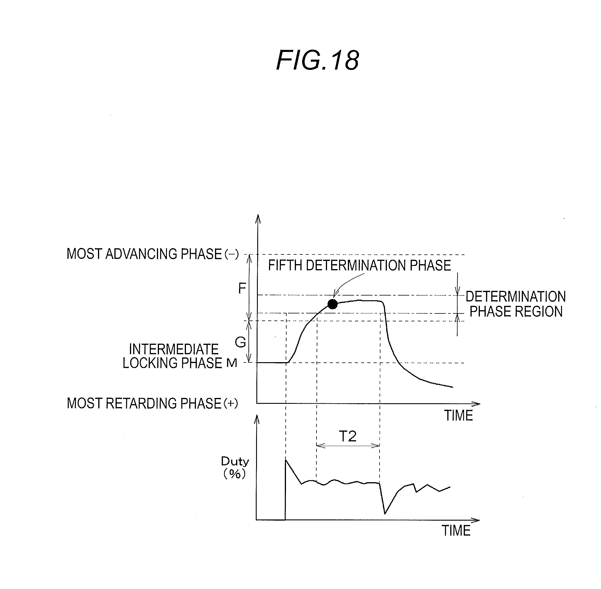
D00013
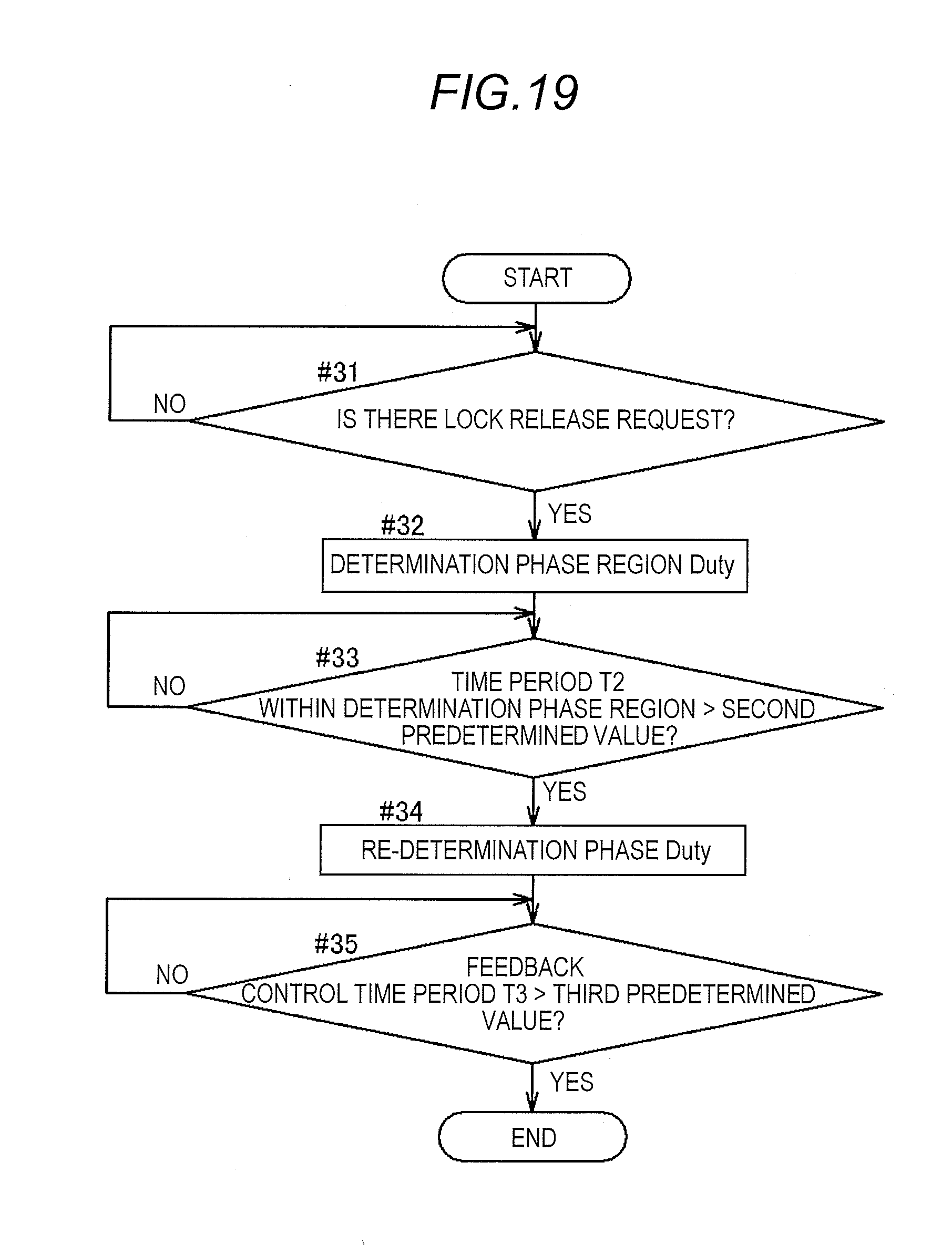
D00014
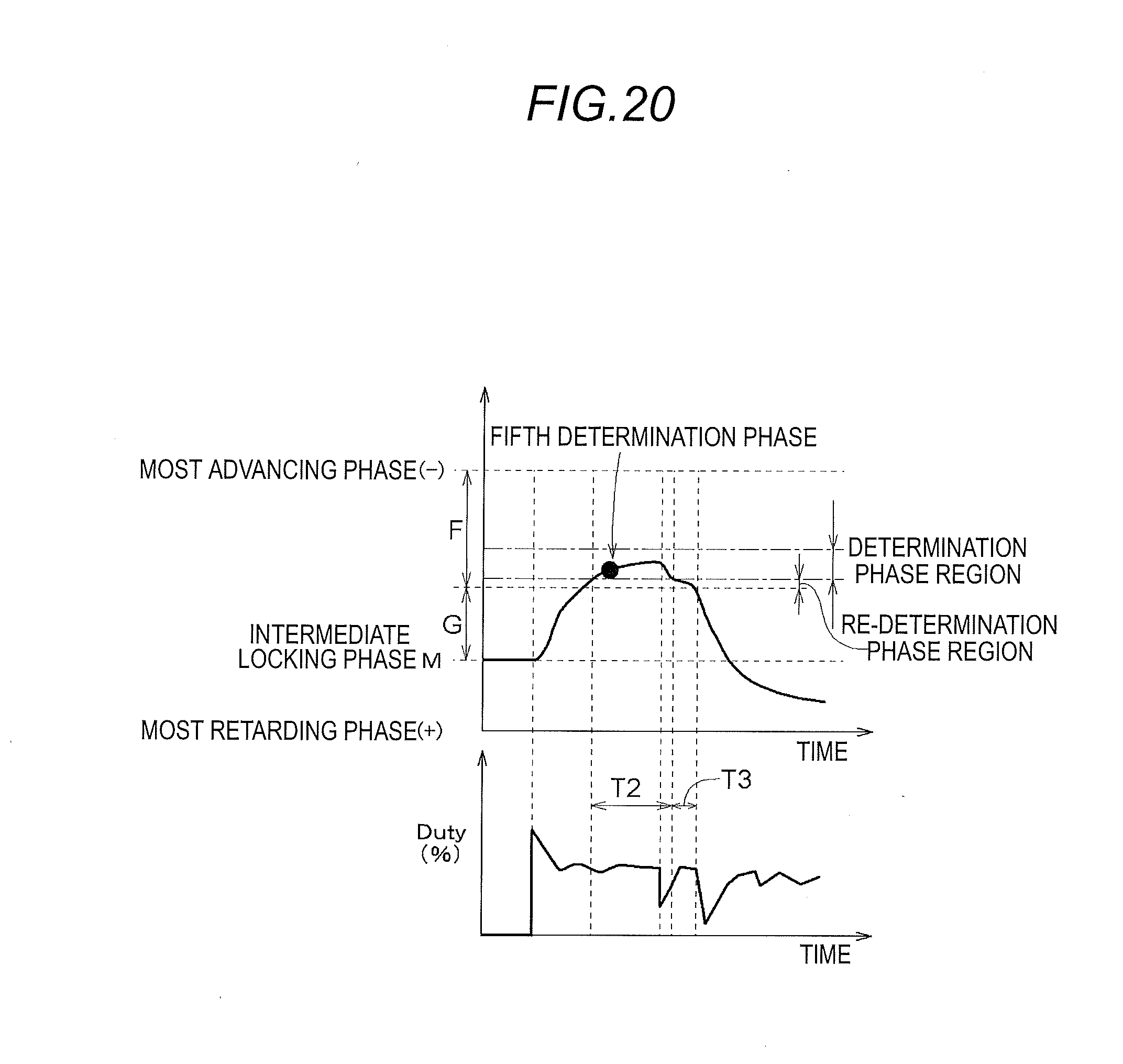
D00015
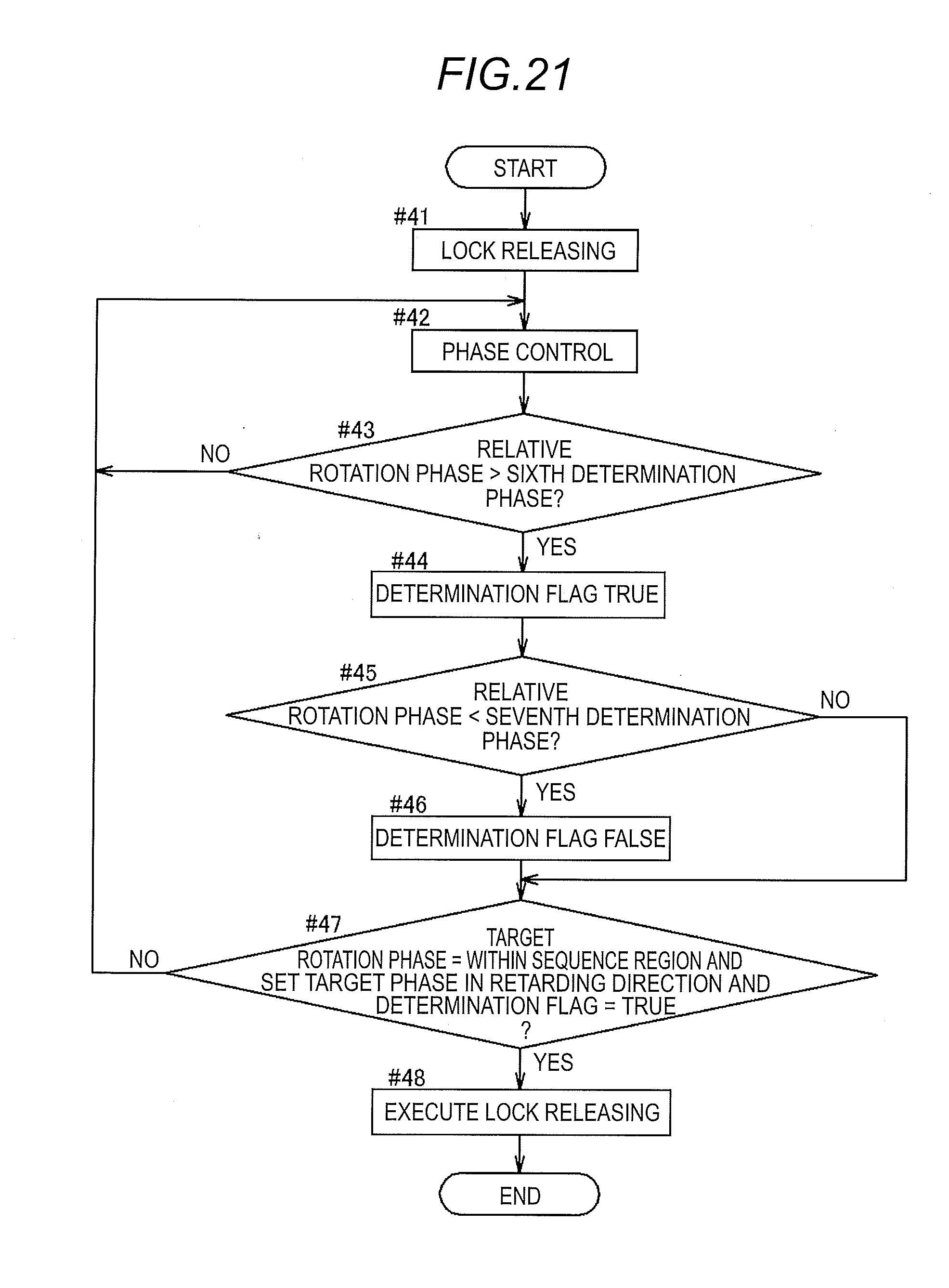
D00016
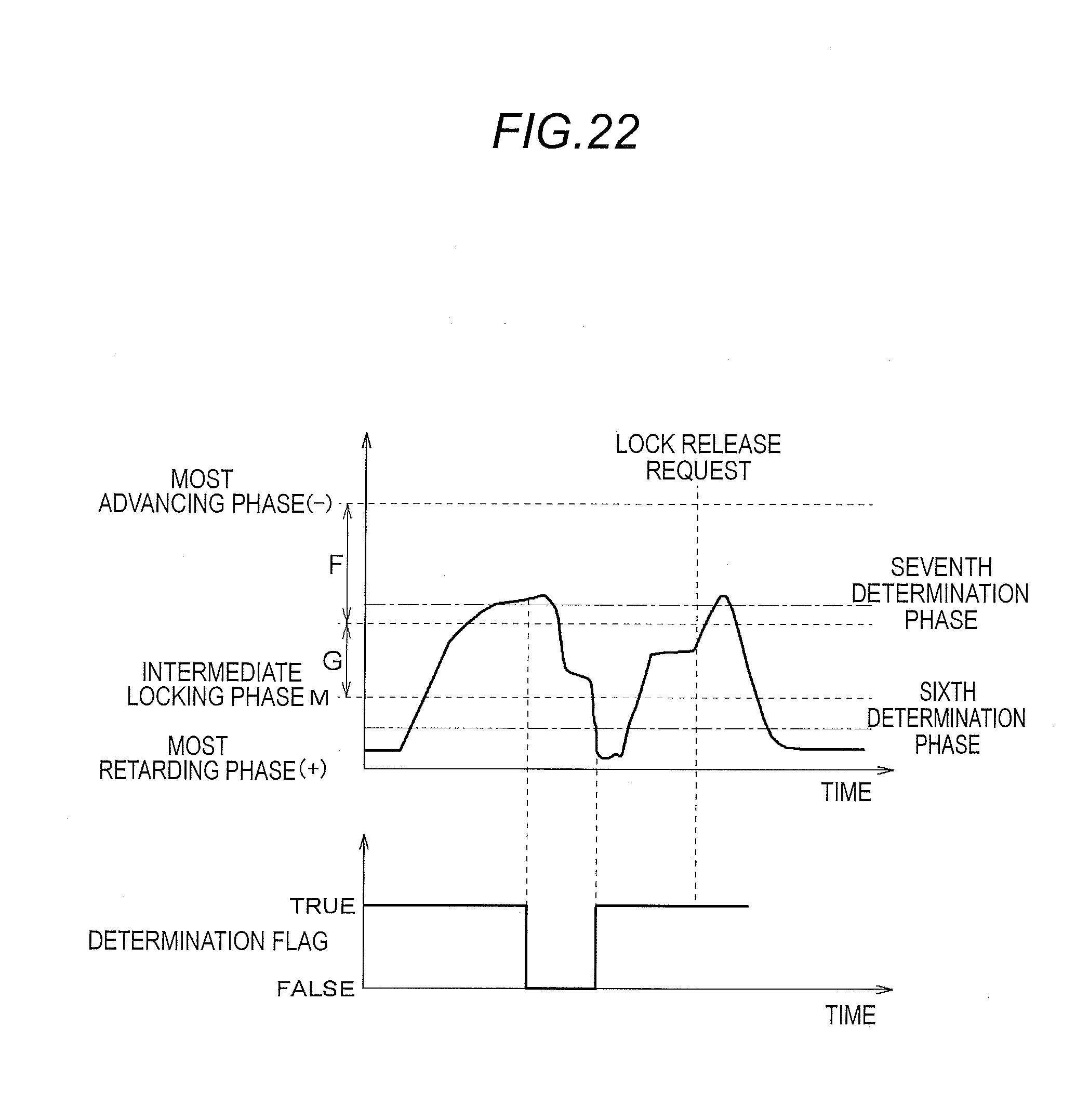
XML
uspto.report is an independent third-party trademark research tool that is not affiliated, endorsed, or sponsored by the United States Patent and Trademark Office (USPTO) or any other governmental organization. The information provided by uspto.report is based on publicly available data at the time of writing and is intended for informational purposes only.
While we strive to provide accurate and up-to-date information, we do not guarantee the accuracy, completeness, reliability, or suitability of the information displayed on this site. The use of this site is at your own risk. Any reliance you place on such information is therefore strictly at your own risk.
All official trademark data, including owner information, should be verified by visiting the official USPTO website at www.uspto.gov. This site is not intended to replace professional legal advice and should not be used as a substitute for consulting with a legal professional who is knowledgeable about trademark law.