Yieldable Bearing Block
Stankus; John C. ; et al.
U.S. patent application number 16/326781 was filed with the patent office on 2019-06-13 for yieldable bearing block. The applicant listed for this patent is FCI Holdings Delaware, Inc.. Invention is credited to Dakota Faulkner, Lumin Ma, John C. Stankus.
| Application Number | 20190178083 16/326781 |
| Document ID | / |
| Family ID | 61691095 |
| Filed Date | 2019-06-13 |


| United States Patent Application | 20190178083 |
| Kind Code | A1 |
| Stankus; John C. ; et al. | June 13, 2019 |
Yieldable Bearing Block
Abstract
A mine roof bolting system including a bearing member having a first member, a second member spaced apart from the first member, and apertures defined through each of the first and second members, and a mine roof bolt extending through the apertures. When a load is applied to the mine roof bolting system, the bearing member yields or deforms. Also, a method for providing a roof support in an underground mine including providing the bearing member and inserting a mine roof bolt through the apertures of the bearing member and into a borehole in a mine roof, wherein the bearing member yields upon application of a load in excess of a predetermined load.
| Inventors: | Stankus; John C.; (Canonsburg, PA) ; Faulkner; Dakota; (New Kensington, PA) ; Ma; Lumin; (Pittsburgh, PA) | ||||||||||
| Applicant: |
|
||||||||||
|---|---|---|---|---|---|---|---|---|---|---|---|
| Family ID: | 61691095 | ||||||||||
| Appl. No.: | 16/326781 | ||||||||||
| Filed: | September 25, 2017 | ||||||||||
| PCT Filed: | September 25, 2017 | ||||||||||
| PCT NO: | PCT/US17/53192 | ||||||||||
| 371 Date: | February 20, 2019 |
Related U.S. Patent Documents
| Application Number | Filing Date | Patent Number | ||
|---|---|---|---|---|
| 62399693 | Sep 26, 2016 | |||
| Current U.S. Class: | 1/1 |
| Current CPC Class: | E21D 20/00 20130101; E21D 21/0086 20130101; F16B 31/02 20130101 |
| International Class: | E21D 21/00 20060101 E21D021/00; E21D 20/00 20060101 E21D020/00 |
Claims
1. A mine roof bolting system comprising: a bearing member including a first member, a second member spaced apart from the first member, and apertures defined through each of the first and second members; and a mine roof bolt extending through the apertures, wherein when a load is applied to the mine roof bolting system, the bearing member yields.
2. The mine roof bolting system of claim 1, wherein a gap is provided between the first member and the second member and wherein when a predetermined load is applied to the mine roof bolting system, the gap is reduced.
3. The mine roof bolting system of claim 2, wherein the gap provided between the first member and the second member is at least 1 inch.
4. The mine roof bolting system of claim 1, wherein the bearing member comprises a rectangular steel tube.
5. The mine roof bolting system of claim 1, wherein the mine roof bolt is a cable bolt, a solid bolt, an expandable bolt, or a hollow bolt.
6. The mine roof bolting system of claim 1, further comprising a bearing plate having a bearing surface for contacting rock strata, a contact surface positioned opposite the bearing surface for engaging the bearing member, and an aperture defined through the bearing plate.
7. A mine roof bolting system comprising: a bearing member comprising: a first member defining a first aperture; a second member spaced apart from the first member and defining a second aperture; and a web extending between the first member and the second member and thereby defining a gap between the first member and the second member; and a mine roof bolt extending through the first and second apertures of the bearing member.
8. The mine roof bolting system of claim 7, wherein the mine roof bolt is a cable bolt, a solid bolt, an expandable bolt, or a hollow bolt.
9. The mine roof bolting system of claim 7, further comprising a bearing plate comprising a bearing surface for contacting the mine roof, a contact surface for contacting the bearing member, and an aperture through which the mine roof bolt extends.
10. The mine roof bolting system of claim 7, wherein the first member is substantially parallel to the second member.
11. The mine roof bolting system of claim 7, further comprising another web extending between the first member and the second member, the two webs being spaced apart by the gap.
12. The bearing member of claim 11, wherein, when taken together, the first member, the second member, the first web, and the second web define a central cavity.
13. A method for providing a roof support in an underground mine, the method comprising the steps of: providing a bearing member including a first member, a second member spaced apart from the first member, and apertures defined through each of the first and second members; and inserting a mine roof bolt through the apertures of the bearing member and into a borehole in a mine roof, wherein the bearing member yields upon application of a load in excess of a predetermined load.
14. The method for providing a roof support of claim 13, wherein the mine roof bolt is a cable bolt, a solid bolt, an expandable bolt, or a hollow bolt.
15. The method for providing a roof support of claim 13, further comprising positioning a bearing plate in between the mine roof and the yieldable bearing member.
Description
CROSS-REFERENCE TO RELATED APPLICATION
[0001] This application claims priority to U.S. Provisional Patent Application No. 62/399,693 filed Sep. 26, 2016, the disclosure of which is hereby incorporated in its entirety by reference.
BACKGROUND OF THE INVENTION
Field of the Invention
[0002] The present invention relates to a mine roof bolting system, and more particularly, a mine roof bolting system including a bearing member that yields or deforms when subjected to a load.
Description of Related Art
[0003] The roof of a mine is conventionally supported by tensioning the roof with mine bolts drilled in the mine roof that reinforce the unsupported rock formation behind the roof. Other structures may also be supported, such as walls or ribs of an underground mine; thus use of the term "roof" herein is also applicable to other such structures. The end of the mine bolt may be anchored mechanically to the rock formation by engagement of an expansion assembly on the end of the bolt with the rock formation. Alternatively, the mine roof bolt may be adhesively bonded to the rock formation with a resin bonding material inserted into the bore hole into which the mine roof bolt is inserted. A combination of mechanical anchoring and resin bonding can also be employed by using both an expansion assembly and resin bonding material.
[0004] Cable bolts are used in the mining industry, and particularly, hard rock mining as they provide several advantages over conventional mine roof bolts, for example, ease of handling and installation. Cable bolts are substantially easier to fit into a borehole than the elongated rods of conventional rod bolt systems. Regardless of the height limitations in a mine, cable bolts may be adapted to boreholes of any length due to their flexibility. Moreover, the strength capacity of cables typically exceed that of conventional rod bolts.
[0005] With certain mining conditions, particularly those found in hard rock mining, the rock formation in the mine roof is susceptible to movement or rock burst as a result of mine-induced seismicity, the excavation of perimeter rock, minor seismicities, and the like. Under dynamic loading caused by rock bursts, the conventional mine roof bolts described above are vulnerable to failure.
SUMMARY OF THE INVENTION
[0006] The present invention includes a simple, low cost, and easy to manufacture mine roof bolting system wherein at least a portion of the system deforms to absorb some of the dynamic loading caused by a rock burst or excessive load caused by squeezing ground.
[0007] The present invention is directed to a mine roof bolting system comprising a bearing member having a first member, a second member spaced apart from the first member, and apertures defined through each of the first and second members; and a mine roof bolt extending through the apertures. When a load is applied to the mine roof bolting system, the bearing member yields.
[0008] The present invention is also directed to a mine roof bolting system comprising a bearing member comprising a first member defining a first aperture, a second member spaced apart from the first member and defining a second aperture, and a web extending between the first member and the second member and thereby defining a gap between the first member and the second member; and a mine roof bolt extending through the first and second apertures of the bearing member.
[0009] The present invention is also directed to a method for providing a roof support in an underground mine. The method includes providing a bearing member as described above and inserting a mine roof bolt through the apertures of the bearing member and into a borehole in a mine roof. The bearing member is adapted to yield upon application of a load in excess of a predetermined load. The mine roof bolt may be a cable bolt, a solid bolt, an expandable (inflatable) bolt, or a hollow bolt.
BRIEF DESCRIPTION OF THE DRAWINGS
[0010] The present invention will now be described in further detail with reference to the accompanying figures, in which:
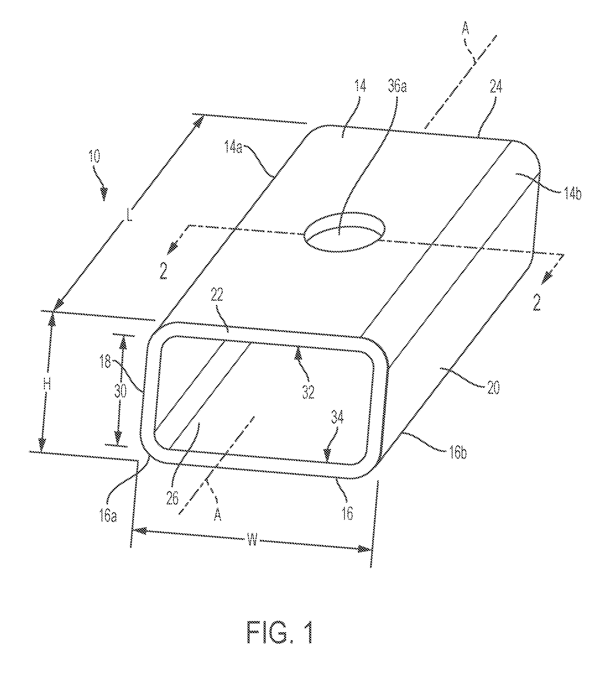
[0011] FIG. 1 is a perspective view of a yieldable bearing member in accordance with the present invention;
[0012] FIG. 2 is a cross-section view of the yieldable bearing member of FIG. 1 taken along line 2-2;
[0013] FIG. 3 is a front elevation view of a mine roof bolting system including a bearing plate, the bearing member of FIG. 1, and a mine roof bolt;
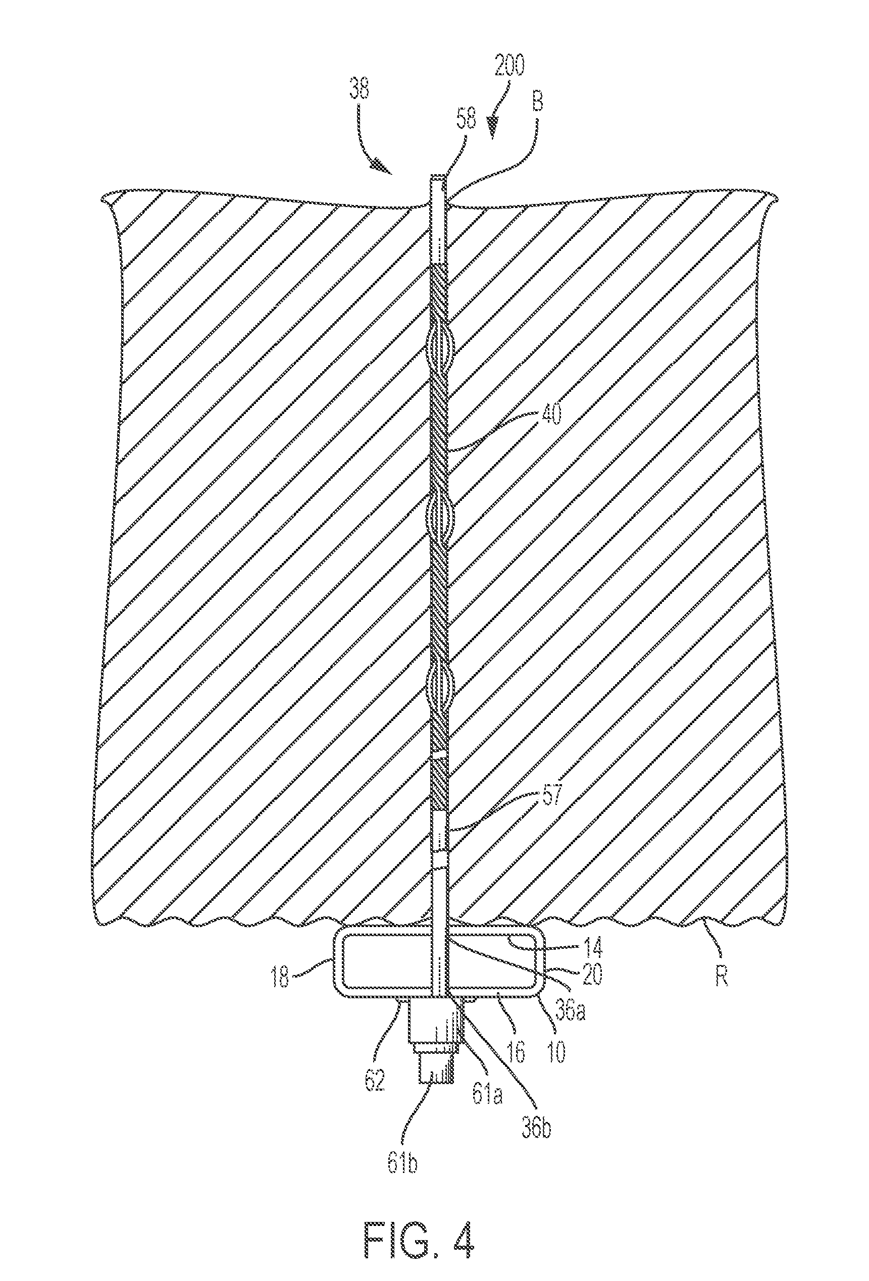
[0014] FIG. 4 is a front elevation view of a mine roof bolting system including the bearing member of FIG. 1 and a mine roof bolt;
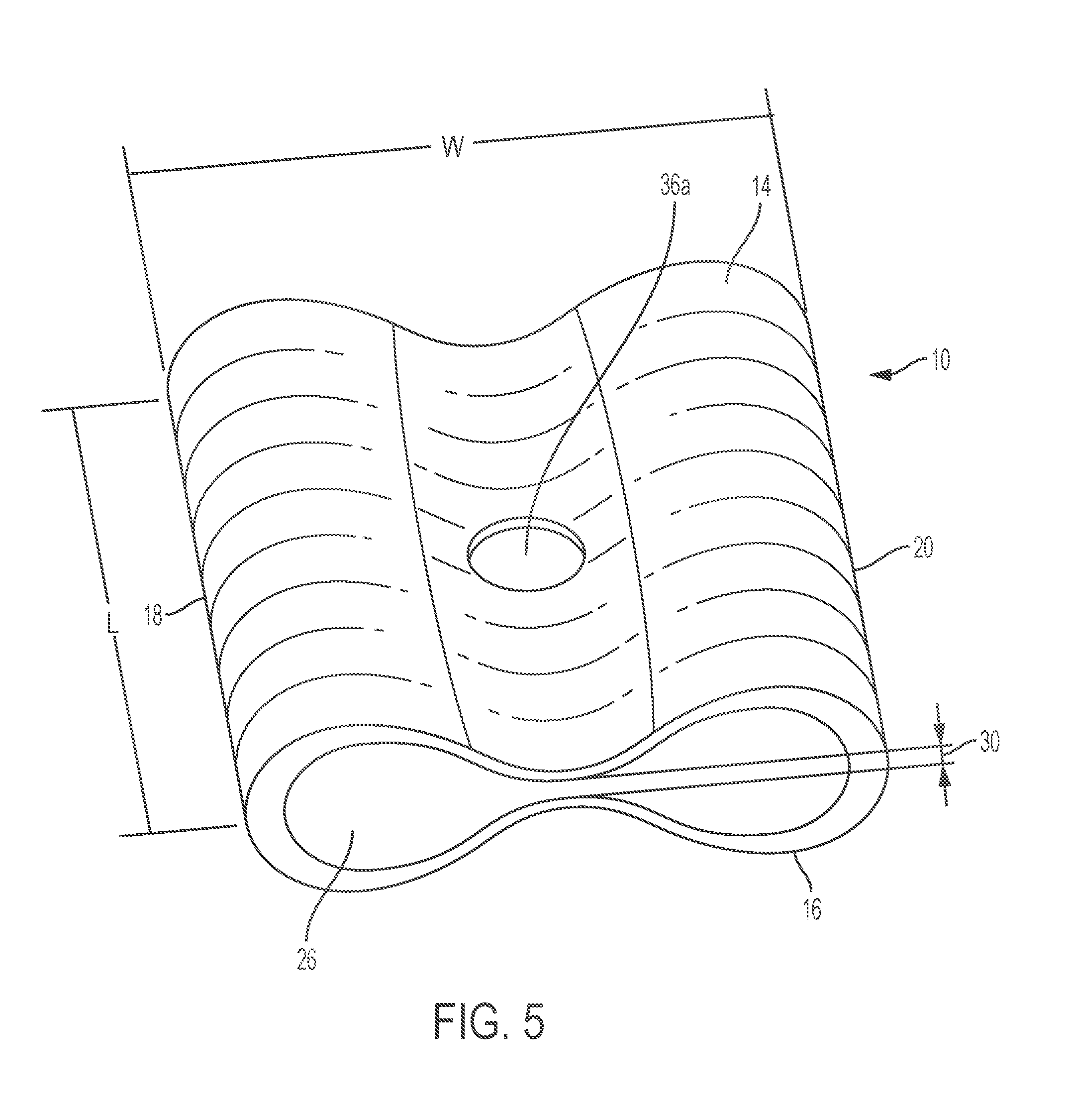
[0015] FIG. 5 is a perspective view of the bearing member of FIG. 1 after the bearing member has yielded; and
[0016] FIG. 6 is a load deflection curve comparing yieldable bearing members made in accordance with the present invention.
DESCRIPTION OF THE INVENTION
[0017] The following description is provided to enable those skilled in the art to make and use the described embodiments contemplated for carrying out the invention. For purposes of the description hereinafter, the terms "upper", "lower", "vertical", "horizontal", "top", "bottom", "lateral", "longitudinal", and derivatives thereof relate to the invention as it is oriented in the drawing figures. It is to be understood that the specific devices illustrated in the attached drawings, and described in the following specification, are simply exemplary embodiments of the invention. Hence, specific dimension and other physical characteristics related to the embodiments disclosed herein are not to be understood as limiting.
[0018] FIGS. 1 and 2 illustrate a yieldable bearing member made in accordance with the present invention. The yieldable bearing member 10, also referred to herein as a yieldable bearing block, generally includes a first member 14, also referred to as a top member, a second member 16, also referred to as a bottom member, and at least one web 18, 20 extending between the top member 14 and the bottom member 16.
[0019] The top member 14 may be spaced apart from the bottom member 16 and may be substantially parallel to the bottom member 16. The top member 14 and the bottom member may each be in the form of a plate which may take any suitable shape including, but not limited to a rectangle, a square, a trapezoid, a parallelogram, a polygon, and a circle. The web 18, 20 may extend from a first side 14a of the top member 14 to a first side 16a of the bottom member 16. A second web 18, 20 may extend from a second side 14b of the top member 14 to a second side 16b of the bottom member 16. First sides 14a, 16a and second sides 14b, 16b each may include curved portions connecting the top member 14 and the bottom member 16. The top member 14, the bottom member 16, and the two webs 18, 20 may combine to define a central cavity 26 such that the yieldable bearing block 10 has a tubular configuration. The central cavity 26 extends along a central axis A from a first end 22 to a second end 24 of the yieldable bearing block 10 such that a gap 30 is formed between an interior surface 32 of the top member 14 and an interior surface 34 of the bottom member 16. The central cavity 26 may be open, or alternatively, may include a compressible material such as wood, plastic, hard rubber, aerated cement, or the like, to modify the loading/deformation properties of the yieldable bearing block 10.
[0020] In one embodiment, the webs 18, 20 may extend from respective sides 14a, 14b of the top member 14 to respective sides 16a, 16b of the bottom member 16 such that the webs 18, 20 are at right angles to the top member 14 and the bottom member 16. The top member 14 and the bottom member may have the same size and shape and two webs 18, 20 may be provided as shown in FIGS. 1 and 2. The top member 14, the bottom member 16, and the webs 18, 20 combine to define a central cavity 26 having a square or rectangular cross-section.
[0021] In another embodiment, the size and/or shape of top member 14 and the bottom member 16 may be different or the top member 14 may be offset from the bottom member 16 such that the webs 18, 20 are angled with respect to the top member 14 and the bottom member 16. Two webs 18, 20 may be provided such that the top member 14, the bottom member 16, and the webs 18, 20 combine to define a central cavity 26 having a cross-section that is a trapezoid or a parallelogram.
[0022] In a further embodiment, at least one of the top member 14, the bottom member 16, and the webs may be curved. Two webs 18, 20 may be provided such that the top member 14, the bottom member 16, and the webs 18, 20 combine to define a central cavity 26 having a cross-section that is a circle, an ellipse, or a truncated circle having two flat sides and two curved sides.
[0023] The yieldable bearing block 10 may have a length L measured along the central axis A from the first end 22 to the second end 24, a width W measured perpendicular to the central axis A between opposing webs 18, 20, and a height H measured perpendicular to the central axis A between the top member 14 and the bottom member 16. With particular reference to FIG. 2, an exterior surface 28 of the yieldable bearing block 10 and the central cavity 26 define a wall thickness 14' of the top member 14, a wall thickness 16' of the bottom member 16, and wall thicknesses 18' and 20' of the webs 18 and 20, respectively. The wall thickness 14', 16', 18', 20' of each wall 14, 16, 18, 20 may be equal to each other such that the yieldable bearing block 10 has a uniform wall thickness T or may be different from each other in order to provide different portions of the yieldable bearing block 10 with different mechanical properties. For example, the yieldable bearing block 10 may have a uniform wall thickness T of 5/16 inch or 3/8 inch. As is further discussed hereinafter, the length L, width W, height H, and wall thickness T of the yieldable bearing block 10 can be manufactured to provide specific yield and tensile properties for various underground mining conditions, for example, hard rock mining.
[0024] Apertures 36a, 36b for receiving a fastening mechanism, such as a mine roof bolt 38, are defined in the top member 14 and the bottom member 16 of the yieldable bearing block 10. The apertures 36a, 36b may be positioned substantially at each of the centers of the top member 14 and the bottom member 16. The apertures 36a, 36b may be dimensioned to receive an elongated body 40 of a mine roof bolt 38 (FIGS. 3 and 4). For example, the apertures 36a, 36b may be dimensioned to receive a mine roof bolt 38 having a diameter of 0.6 inch or 0.7 inch.
[0025] The yieldable bearing block 10 may be produced from any yieldable material having high strength, for example, steel or aluminum. The material may have a minimum yield strength of 46 ksi and a minimum tensile strength of 58 ksi. One such material is rectangular steel tube, for example, a rectangular tube made of ASTM A500-B steel.
[0026] The yieldable bearing block 10 can be used as part of a mine roof bolting system, such as a mine roof bolting system 100, shown in FIG. 3, including the yieldable bearing block 10, a bearing plate 42, and a mine roof bolt 38, or a mine roof bolting system 200, shown in FIG. 4, including the yieldable bearing block 10 and a mine roof bolt 38.
[0027] Referring to FIG. 5, the yieldable bearing block 10 is designed to yield, or deform, such that the gap 30 of the yieldable bearing block 10 is reduced when a predetermined load, for example, 15 tons or more or 20 tons or more, is applied to the mine roof bolting system 100 or the mine roof bolting system 200.
[0028] Referring to FIG. 3, the mine roof bolting system 100 includes the yieldable bearing block 10, the bearing plate 42, and the mine roof bolt 38. The bearing plate 42 may generally include a planar body 44 having a bearing surface 46 for engaging the mine roof R and a contact surface 48 for engaging the top member 14 of the yieldable bearing block 10. The bearing plate 42 may be made of commercial grade steel. An aperture 50 may be positioned substantially at the center of the planar body 44. The bearing plate 42 may optionally include one or more rib members 52 surrounding the aperture 50 and positioned between the aperture 50 and a peripheral edge 54 of the bearing plate 42. It should be appreciated that other bearing plates known in the art may be used in the system 100.
[0029] The mine roof bolting system 100 may be installed in a mine roof R to provide support to a rock formation. The mine roof bolt 38 is inserted through the apertures 36 of the yieldable bearing block 10 and the aperture 50 of the bearing plate 42 and into a borehole B. The mine roof bolt 38 may be a solid bolt, such as a solid rebar bolt or smooth bar bolt, a cable bolt, an expandable (inflatable) bolt, a hollow bolt, or any other mine roof bolt designed for supporting rock strata as is known in the art. A drive end 60 of the mine roof bolt 38 may include a drive head that does not tension the bolt or may include a tensioning system. Suitable tensioning systems include an externally threaded bolt with a tensioning nut optionally having a shear pin or breakout portion or the like threaded thereon, a barrel and wedge assembly on a cable bolt or other drive heads as are known in the art for installing mine roof bolts.
[0030] By way of example, the mine roof bolt 38 may be a cable bolt formed of a selected length of a flexible multi-strand steel cable 56 having an anchor end portion 58 and a drive end portion 60 including a barrel and wedge assembly 61a and a drive nut 61b. Between the anchor end portion 58 and the drive end portion 60, the cable 56 is flexible and extends a length as determined by the length of the borehole B in the rock formation. A stiffening tube 57 may enclose the flexible multi-strand steel cable 56 at a proximal end thereof, adjacent the barrel and wedge assembly 61a. A washer 62 may optionally be placed between the bottom member 16 of the yieldable bearing block 10 and the barrel and wedge assembly 61a such that the yieldable bearing block 10 does not directly contact the barrel and wedge assembly 61a.
[0031] When the mine roof bolting system 100 experiences loading due to a shift in the surrounding rock strata, the yieldable bearing block 10 yields, or deforms, such that the gap 30 of the yieldable bearing block 10 is reduced. As the yieldable bearing block 10 yields, the mine roof bolting system 100 absorbs some of the dynamic load such that the mine roof system 100 can support a greater load than a comparable system not including the yieldable bearing block 10.
[0032] Referring to FIG. 4, the mine roof bolting system 200 includes the yieldable bearing block 10 and a mine roof bolt 38. The mine roof bolting system 200 is substantially the same as the mine roof bolting system 100, but does not include the bearing plate 42. Instead, the top member 14 of the yieldable bearing block 10 directly engages the mine roof R such that the yieldable bearing block 10 serves a dual function, acting as both the yieldable bearing block 10 and the bearing plate 42. For example, in the mine roof bolting system 200, the yieldable bearing block 10 may be at least 36 square inches.
[0033] When the mine roof system 200 experiences loading due to natural forces of the mine, the yieldable bearing block 10 yields, or deforms, such that the gap 30 of the yieldable bearing block 10 is reduced. As the yieldable bearing block 10 yields, the mine roof bolting system 100 absorbs some of the dynamic load such that mine roof system 200 can support a greater load than a comparable system not including the yieldable bearing block 10.
[0034] The following tests were conducted to demonstrate the general principles of the present invention. The invention should not be considered to be limited to the specific tests presented herein.
Examples
[0035] Ten yieldable bearing blocks 10 having a rectangular cross-section and various lengths L, widths W, heights H, and wall thicknesses T, were tested to determine a maximum load and a maximum yield (i.e., maximum deflection) that each of the ten yieldable bearing blocks 10 could withstand prior to failure. A load was applied to the top member 14 of the yieldable bearing blocks 10 using a rod having a 1.75 inch diameter to simulate the housing of a mine roof bolt having a 0.6 inch diameter. The maximum load and deflection achieved before the gap between the top member 14 and the bottom member 16 is at least partially closed as the top member 14 and the bottom member 16 move toward one another under the load as shown in FIG. 5 was measured. The results of the tests are shown below in Table 1.
TABLE-US-00001 TABLE 1 Test results showing maximum load and deflection Tube size Sample (W .times. H .times. T) length Max load Max deflection Test # (inch) (inch) (ton) (inch) 1 4 .times. 3 .times. 3/8 4.5 24 1.95 2 4.0 22 1.88 3 3.5 20 1.76 4 4 .times. 2 .times. 5/16 4.5 21 1.21 5 4.0 20 1.16 6 3.5 18 1.11 7 3 .times. 2 .times. 5/16 4.5 34 1.22 8 4.0 33 1.20 9 3.5 31 1.12 10 3.0 24 1.06
[0036] Load deflection curves comparing the results of the yieldable bearing blocks of Tests 9 and 10 having a length of 3.5 inches and a length of 3 inches, respectively, are shown in FIG. 6. The results shown in FIG. 6 demonstrate that a load up to a predetermined load (e.g., about 25 tons for Test 9 at a length of 3 inches and about 20 tons for Test 10 at a length of 3.5 inches) can be applied before maximum deflection is achieved. A mine roof support system incorporating the yieldable bearing block of the present invention can withstand an added load (e.g., 20-25 tons as shown in Tests 9 and 10), allowing the system to yield upon application of the load.
[0037] The yieldable bearing block provided herein provides an easy to manufacture and low cost system for increasing the load for which a mine roof bolting system can support. The systems disclosed herein are particularly advantageous in hard rock mining under which dynamic loading is caused by squeezing and rock bursts.
[0038] While embodiments of the yieldable bearing block are shown in the accompanying figures and described hereinabove in detail, other embodiments will be apparent to, and readily made by, those skilled in the art without departing from the scope and spirit of the invention. Accordingly, the foregoing description is intended to be illustrative rather than restrictive. The disclosure described hereinabove is defined by the appended claims and all changes to the disclosure that fall within the meaning and the range of equivalency of the claims are to be embraced within its scope.
* * * * *
D00000
D00001
D00002
D00003
D00004
D00005
D00006
XML
uspto.report is an independent third-party trademark research tool that is not affiliated, endorsed, or sponsored by the United States Patent and Trademark Office (USPTO) or any other governmental organization. The information provided by uspto.report is based on publicly available data at the time of writing and is intended for informational purposes only.
While we strive to provide accurate and up-to-date information, we do not guarantee the accuracy, completeness, reliability, or suitability of the information displayed on this site. The use of this site is at your own risk. Any reliance you place on such information is therefore strictly at your own risk.
All official trademark data, including owner information, should be verified by visiting the official USPTO website at www.uspto.gov. This site is not intended to replace professional legal advice and should not be used as a substitute for consulting with a legal professional who is knowledgeable about trademark law.