Method for Estimating Steering Wheel Torque of Vehicle
Sung; Woo Je ; et al.
U.S. patent application number 16/123793 was filed with the patent office on 2019-06-13 for method for estimating steering wheel torque of vehicle. The applicant listed for this patent is Hyundai Motor Company, Kia Motors Corporation. Invention is credited to Seung Bum Cho, Jong Ho Lee, Woo Je Sung.
| Application Number | 20190176885 16/123793 |
| Document ID | / |
| Family ID | 66734494 |
| Filed Date | 2019-06-13 |


View All Diagrams
| United States Patent Application | 20190176885 |
| Kind Code | A1 |
| Sung; Woo Je ; et al. | June 13, 2019 |
Method for Estimating Steering Wheel Torque of Vehicle
Abstract
A method of operating a motor vehicle includes sensing a sensed torque based on a driver interaction with a steering wheel that is part of an electric power steering system, the sensed torque being sensed using a torque sensor, calculating driver steering wheel torque using state variables of a steering system model based on the electric power steering system, and controlling a difference between the driver steering wheel torque calculated from the steering system model and sensed torque sensed by the torque sensor to converge to zero through a controller.
| Inventors: | Sung; Woo Je; (Yongin-si, KR) ; Lee; Jong Ho; (Incheon, KR) ; Cho; Seung Bum; (Gwacheon-si, KR) | ||||||||||
| Applicant: |
|
||||||||||
|---|---|---|---|---|---|---|---|---|---|---|---|
| Family ID: | 66734494 | ||||||||||
| Appl. No.: | 16/123793 | ||||||||||
| Filed: | September 6, 2018 |
| Current U.S. Class: | 1/1 |
| Current CPC Class: | G06F 30/17 20200101; B62D 6/10 20130101 |
| International Class: | B62D 6/10 20060101 B62D006/10 |
Foreign Application Data
| Date | Code | Application Number |
|---|---|---|
| Dec 13, 2017 | KR | 10-2017-0171116 |
Claims
1. A method for estimating steering wheel torque of a vehicle, the method comprising: modeling a steering system for designing an electric power steering system; constructing a steering system model for calculating a driver steering wheel torque T.sub.driver using state variables from the steering system modeling; and controlling a difference between the driver steering wheel torque T.sub.driver calculated from the steering system model and a torque T.sub.sensor sensed by a torque sensor to converge to zero through a controller.
2. The method of claim 1, wherein the steering system model is constructed by: inducing a change rate P.sub.sw of momentum of a steering wheel and a displacement angle q.sub.u of a torsion bar from the state variables in the steering system modeling; and inducing relationship between the driver steering wheel torque and the torque sensed by a torque sensor, using the change rate P.sub.sw of momentum of a steering wheel and the displacement angle q.sub.u of a torsion bar in order to calculate the driver steering wheel torque.
3. The method of claim 2, wherein the change rate P.sub.sw of momentum of a steering wheel is induced as P . sw = T driver - q u k u - b u P sw J sw + b u gG .omega. m , ##EQU00004## where T.sub.sw is steering wheel torque [=Driver torque (T.sub.driver)], q.sub.u is displacement angle (or torsion angle) of a torsion bar, k.sub.u is rigidity of the torsion bar, b.sub.u is compliance (or damping constant) of a steering column, J.sub.sw is inertia of a steering wheel, gG is a gear ratio of a reducer, and .omega..sub.m is an angular speed of a motor.
4. The method of claim 2, wherein the displacement angle q.sub.u of a torsion bar is induced as q . u = P sw J sw - gG .omega. m , ##EQU00005## where P.sub.sw is a change rate of momentum (moment torque) of a steering wheel, J.sub.sw is inertia of a steering wheel, gG is a gear ratio of a reducer, and .omega..sub.m is an angular speed of a motor.
5. The method of claim 2, wherein the driver steering wheel torque is calculated by T driver - q u k u = P . sw + b u ( P sw J sw + gG .omega. m ) , ##EQU00006## where T.sub.driver is driver steering wheel torque, q.sub.uk.sub.u is torque sensed by a torque sensor, P.sub.sw is a change rate of momentum (or moment torque) of a steering wheel, b.sub.u is compliance (or damping constant) of a steering column, J.sub.sw is inertia of the steering wheel, gG is a gear ratio of a reducer, and .omega..sub.m is an angular speed of a motor.
6. A method of operating a vehicle, the method comprising: sensing a sensed torque based on a driver interaction with a steering wheel that is part of an electric power steering system, the sensed torque being sensed using a torque sensor; calculating driver steering wheel torque using state variables of a steering system model based on the electric power steering system; and controlling a difference between the driver steering wheel torque calculated from the steering system model and sensed torque sensed by the torque sensor to converge to zero through a controller.
7. The method of claim 6, further comprising controlling steering of the vehicle based on the controlled difference.
8. The method of claim 6, further comprising constructing the steering system model.
9. The method of claim 8, wherein the steering system model is constructed by: inducing a change rate of momentum of a steering wheel and a displacement angle q.sub.u of a torsion bar from the state variables in the steering system modeling; and inducing relationship between the driver steering wheel torque and the sensed torque sensed by a torque sensor, using the change rate of momentum of a steering wheel and the displacement angle of a torsion bar in order to calculate the driver steering wheel torque.
10. The method of claim 9, wherein the change rate of momentum P.sub.sw of a steering wheel is induced as P . sw = T driver - q u k u - b u P sw J sw + b u gG .omega. m , ##EQU00007## where T.sub.driver is the driver steering wheel torque, T.sub.sensor is the sensed torque, q.sub.u is the displacement angle (or torsion angle) of a torsion bar, k.sub.u is rigidity of the torsion bar, b.sub.u is compliance (or damping constant) of a steering column, J.sub.sw is inertia of a steering wheel, gG is a gear ratio of a reducer, and .omega..sub.m is an angular speed of a motor.
11. The method of claim 9, wherein the displacement angle q.sub.u of a torsion bar is induced as q . u = P sw J sw - gG .omega. m , ##EQU00008## where P.sub.sw is a change rate of momentum (moment torque) of a steering wheel, J.sub.sw is inertia of a steering wheel, gG is a gear ratio of a reducer, and .omega..sub.m is an angular speed of a motor.
12. The method of claim 9, wherein the driver steering wheel torque is calculated by T driver - q u k u = P . sw + b u ( P sw J sw + gG .omega. m ) , ##EQU00009## where T.sub.driver is the driver steering wheel torque, q.sub.uk.sub.u is torque sensed by a torque sensor, P.sub.sw is a change rate of momentum (or moment torque) of a steering wheel, b.sub.u is compliance (or damping constant) of a steering column, J.sub.sw is inertia of the steering wheel, gG is a gear ratio of a reducer, and .omega..sub.m is an angular speed of a motor.
13. The method of claim 6, wherein the steering system model comprises a model constructed by an inducement of a change rate of momentum of the steering wheel and a displacement angle of a torsion bar from the state variables in the steering system modeling, and a relationship between the driver steering wheel torque and the sensed torque sensed by a torque sensor, the relationship using the change rate of momentum of a steering wheel and the displacement angle of a torsion bar in order to calculate the driver steering wheel torque.
14. The method of claim 13, wherein the change rate of momentum P.sub.sw of a steering wheel is induced as P . sw = T driver - q u k u - b u P sw J sw + b u gG .omega. m , ##EQU00010## where T.sub.driver is the driver steering wheel torque, T.sub.sensor is the sensed torque, T.sub.sw is steering wheel torque [=Driver torque (T.sub.driver)], q.sub.u is the displacement angle (torsion angle) of a torsion bar, k.sub.u is rigidity of the torsion bar, b.sub.u is compliance (damping constant) of a steering column, J.sub.sw is inertia of a steering wheel, gG is a gear ratio of a reducer, and .omega..sub.m is an angular speed of a motor.
15. The method of claim 13, wherein the displacement angle q.sub.u of a torsion bar is induced as q . u = P sw J sw - gG .omega. m , ##EQU00011## where P.sub.sw is a change rate of momentum (moment torque) of a steering wheel, J.sub.sw is inertia of a steering wheel, gG is a gear ratio of a reducer, and .omega..sub.m is an angular speed of a motor.
16. The method of claim 13, wherein the driver steering wheel torque is calculated by T driver - q u k u = P . sw + b u ( P sw J sw + gG .omega. m ) , ##EQU00012## where T.sub.driver is the driver steering wheel torque, q.sub.uk.sub.u is torque sensed by a torque sensor, P.sub.sw is a change rate of momentum (or moment torque) of a steering wheel, b.sub.u is compliance (or damping constant) of a steering column, J.sub.sw is inertia of the steering wheel, gG is a gear ratio of a reducer, and .omega..sub.m is an angular speed of a motor.
17. A method for operating a vehicle, the method comprising: constructing a steering system model for calculating driver steering wheel torque using state variables in a steering system model constructed by an inducement of a change rate of momentum of a steering wheel and a displacement angle of a torsion bar from the state variables in the steering system modeling and by a relationship between the driver steering wheel torque and a torque sensed by a torque sensor, the relationship using the change rate of momentum of a steering wheel and the displacement angle of a torsion bar in order to calculate the driver steering wheel torque; sensing a sensed torque based on a driver interaction with the steering wheel; and steering the vehicle based on the steering system model and the sensed torque.
18. The method of claim 17, wherein the change rate of momentum P.sub.sw of a steering wheel is induced as P . sw = T driver - q u k u - b u P sw J sw + b u gG .omega. m , ##EQU00013## where T.sub.sw is steering wheel torque [=Driver torque (T.sub.driver)], q.sub.u is displacement angle (or torsion angle) of a torsion bar, k.sub.u is rigidity of the torsion bar, b.sub.u is compliance (or damping constant) of a steering column, J.sub.sw is inertia of a steering wheel, gG is a gear ratio of a reducer, and .omega..sub.m is an angular speed of a motor.
19. The method of claim 17, wherein the displacement angle q.sub.u of a torsion bar is induced as q . u = P sw J sw - gG .omega. m , ##EQU00014## where P.sub.sw is a change rate of momentum (or moment torque) of a steering wheel, J.sub.sw is inertia of a steering wheel, gG is a gear ratio of a reducer, and .omega..sub.m is an angular speed of a motor.
20. The method of claim 17, wherein the driver steering wheel torque is calculated by T driver - q u k u = P . sw + b u ( P sw J sw + gG .omega. m ) , ##EQU00015## where T.sub.driver is driver steering wheel torque (=T.sub.sw), q.sub.uk.sub.u is torque sensed by a torque sensor, P.sub.sw is a change rate of momentum (or moment torque) of a steering wheel, b.sub.u is compliance (or damping constant) of a steering column, J.sub.sw is inertia of the steering wheel, gG is a gear ratio of a reducer, and .omega..sub.m is an angular speed of a motor.
Description
CROSS-REFERENCE TO RELATED APPLICATIONS
[0001] This application claims priority to Korean Patent Application No. 10-2017-0171116, filed on Dec. 13, 2017, which application is hereby incorporated herein by reference.
TECHNICAL FIELD
[0002] The present invention relates to a method for estimating steering wheel torque of a vehicle.
BACKGROUND
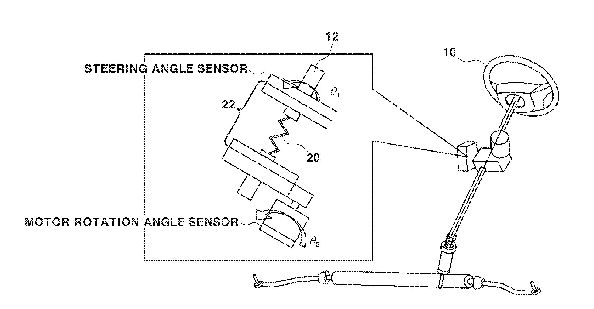
[0003] An electric power steering system (e.g., a motor-driven power steering or MDPS system) is a kind of vehicle speed-sensitive power steering apparatus for changing a steering force on the basis of a driving speed. In this system, an ECU of an electric power steering module provides an optimum steering feeling to a driver by controlling a steering angle and the operation of a motor on the basis of a vehicle speed.
[0004] The MDPS system that is an example of the electric power steering system is classified into a column type in which a motor is mounted on a steering column and a rack type in which a motor is mounted on a rack bar connected to a steering shaft.
[0005] The electric power steering system calculates the intention of turning a steering wheel (driver torque) by a driver on the basis of a torque sensing value of a torque sensor that senses torque of a torsion bar coupled to a steering column.
[0006] For example, as shown in FIG. 1, a torsion bar 20 is coupled to a steering shaft 12 connected to a steering wheel 10 and torque sensors 22 are mounted on the upper end and the lower end of the torsion bar 20. In this configuration, the torque sensors 22 sense torque of the torsion bar 20 and the torque that is used as driver steering wheel torque that is torque applied by a driver to turn the steering wheel.
[0007] However, the torque sensing value of the torque sensors based on a nonlinear characteristic of a mechanism and the driver steering wheel torque (the intention of steering of a driver) when the driver actually turns a steering wheel may be different in accordance with the positions of the torque sensors in the electric power steering system. Accordingly, it is difficult to accurately estimate the driver steering wheel torque (the intention of steering of a driver) when controlling the electric power steering system on the basis of the torque sensing signal from the torque sensors. Therefore, the torque sensing value of the torque sensors are unavoidably considered as the driver steering wheel torque and used for controlling various parts of the electric power steering system.
SUMMARY
[0008] The present invention relates to a method for estimating steering wheel torque of a vehicle. Particular embodiments relate to a method for estimating steering wheel torque of a vehicle that is able to accurately estimate torque applied by a driver operating a steering wheel in order to improve precision in feedback control of an electric power steering system.
[0009] If it is possible to accurately know the driver steering wheel torque that is the torque actually applied by a driver to turn a steering wheel, it is possible to compensate for the driver steering wheel torque more accurately and intuitionally through various control logics of the electric power steering (MDPS) system, and accordingly, it is possible to control performance of the electric power steering (MDPS) system.
[0010] Embodiments of the present invention can solve problems and provide a method for estimating steering wheel torque of a vehicle, the method being able to improve the performance of steering a vehicle by precisely assisting an electric power steering system by accurately estimating steering wheel torque (driver's steering intention) in view of the driver through the behavior of the electric power steering system on the basis of the dynamic characteristics of the electric power steering system and a driver model so that the steering wheel torque can be reflected to a feedback control logic of the electric power steering system.
[0011] For example, a method for estimating steering wheel torque of a vehicle includes modeling a steering system for designing an electric power steering system; constructing a steering system model for calculating driver steering wheel torque using state variables in the steering system modeling; and controlling a difference between the driver steering wheel torque Tdriver calculated from the steering system model and torque Tsensor sensed by a torque sensor to converge to zero through a controller.
[0012] Embodiments of the present invention can provide the following effects.
[0013] First, it is possible to precisely assist an electric power steering system by accurately estimating steering wheel torque (driver's steering intention) in view of the driver so that the steering wheel torque can be reflected to a feedback control logic of the electric power steering system.
[0014] That is, by replacing driver torque that is a driver feedback signal by not torque sensed by a torque sensor, but a driver effort for directly operating a steering wheel, it is possible to improve the control precision in feedback control of an electric power steering system, and accordingly, it is possible to more precisely assist a steering force.
[0015] Second, there may be distortion when sensing torque through a torque sensor due to the weight and inertia of a steering column assembly even if a driver take hands off the steering wheel, but the distortion can be compensated by the driver steering wheel torque estimator of the present invention.
[0016] Third, the present invention can be used to determine conditions in which a driver directly operates a steering wheel when developing technologies such as automatic parking, keeping a lane, self-driving on a highway, unmanned self-driving etc.
BRIEF DESCRIPTION OF THE DRAWINGS
[0017] The above and other objects, features and other advantages of the present invention will be more clearly understood from the following detailed description when taken in conjunction with the accompanying drawings, in which:
[0018] FIG. 1 is a schematic view showing the configuration of an electric power steering system;
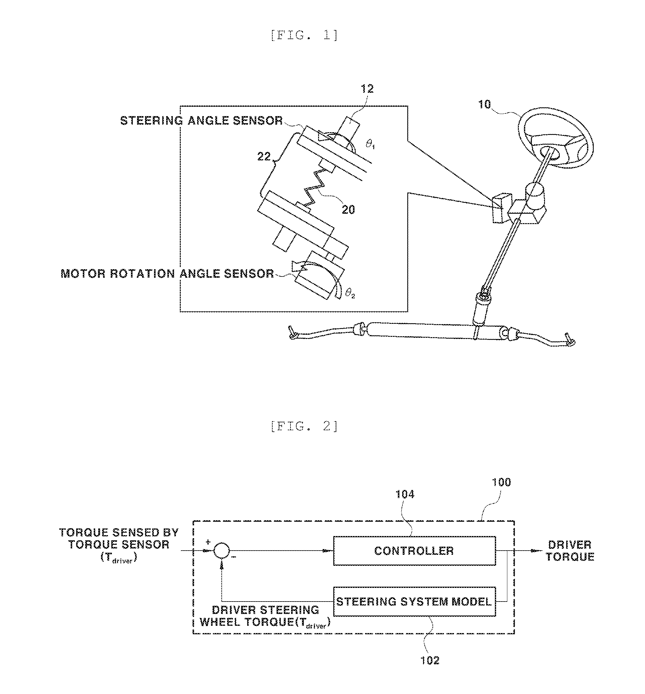
[0019] FIG. 2 is a view showing a steering wheel torque estimator of a vehicle according to the present invention; and
[0020] FIG. 3 is a schematic view showing a modeling example of a steering system model for a method for estimating steering wheel torque of a vehicle of the present invention.
DETAILED DESCRIPTION OF ILLUSTRATIVE EMBODIMENTS
[0021] Exemplary embodiments of the present invention will be described hereafter in detail with reference to the accompanying drawings.
[0022] Embodiments of the present invention can configure a driver torque estimator that estimates actual driver steering wheel torque using state variables of components included in steering system modeling in consideration of a difference between actual driver steering wheel torque T.sub.driver when a driver turns a steering wheel and torque T.sub.sensor sensed as driver steering wheel torque by a torque sensor so that the difference between the estimated driver steering wheel torque T.sub.driver and the T.sub.sensor torque sensed by the torque sensor can be used to compensate for target steering torque that is input to a feedback controller of an electric power steering system and the steering force of the electric power steering system can be precisely assisted.
[0023] FIG. 2 is a view showing a method for estimating steering wheel torque of a vehicle of the present invention, in which reference numeral `100` indicates a driver torque estimator.
[0024] The driver torque estimator converges the difference between driver steering wheel torque estimated from state variables of components in steering system modeling to be described below and torque sensed by a torque sensor to zero.
[0025] Referring to FIG. 2, the driver torque estimator 100 includes a steering system model 102 that estimates and output driver steering wheel torque and a controller 104 that performs control for converging the difference between driver steering wheel torque estimated by the steering system model 102 and torque sensed by a torque sensor to zero.
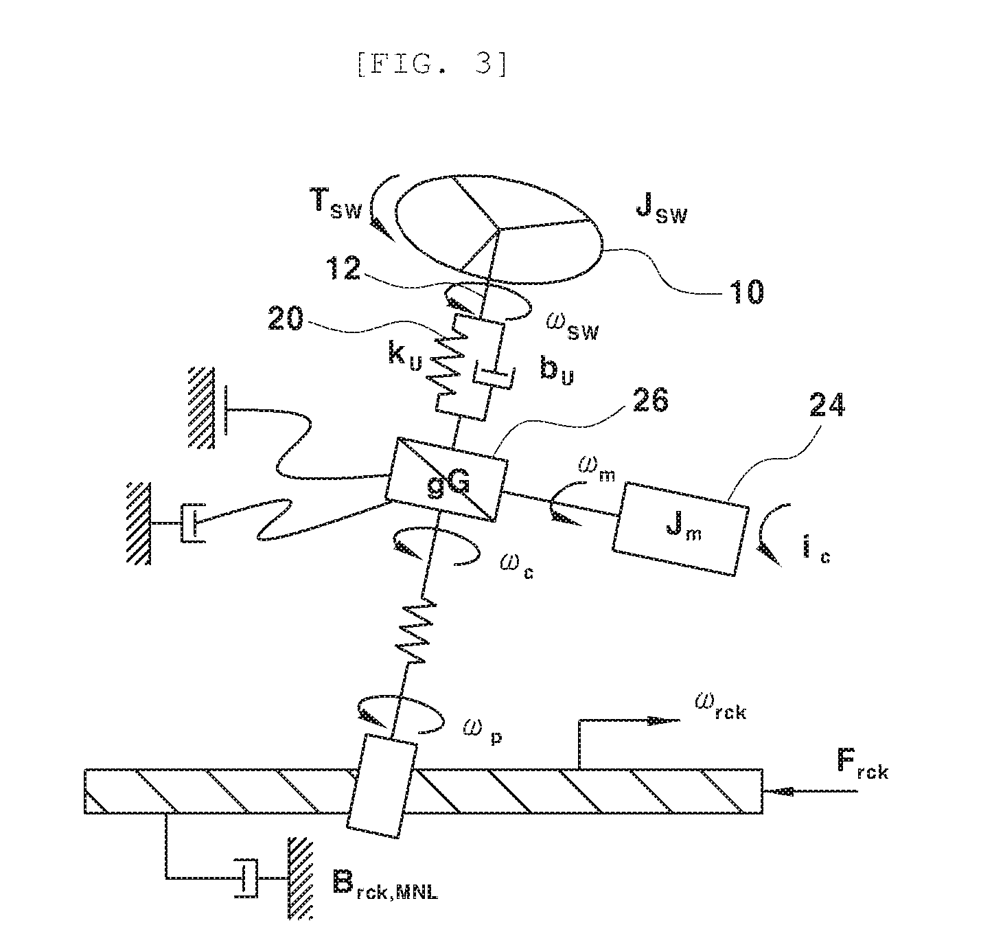
[0026] FIG. 3 is a view showing a modeling example of a steering system model for a method for estimating steering wheel torque of a vehicle of the present invention.
[0027] First, a steering system for designing an electric power steering system, which includes a steering wheel 10, a 20 torsion bar coupled to a steering shaft 12 connected to the steering wheel 10, a torque sensor (not shown) sensing torque of the torsion bar, a motor 24 and reducer 26 for assisting a steering force that is applied to the steering shaft, etc., is modeled using a bond graph etc.
[0028] The state variables of the components in the steering system modeling shown in FIG. 3 are defined as follows. [0029] J.sub.sw: Inertia of steering wheel [0030] .omega..sub.sw: Angular speed of steering shaft [0031] T.sub.sw: Steering wheel torque[=Driver torque (T.sub.driver)] [0032] k.sub.u: Rigidity of torsion bar [0033] b.sub.u: Compliance (damping constant) of steering column [0034] q.sub.u: Displacement angle (torsion angle) of torsion bar [0035] P.sub.sw: Change rate of momentum (moment torque) of steering wheel [0036] gG: Gear ratio of reducer [0037] .omega..sub.w: Angular speed of motor
[0038] Next, a steering system model for estimating driver steering wheel torque using the state variables in the steering system modeling is constructed.
[0039] To this end, the change rate P.sub.sw of momentum of a steering wheel and the displacement angle q.sub.u of a torsion bar are induced as in the following Equations 1 and 2 that are equations of motion made in the steering system modeling.
P . sw = T driver - q u k u - b u P sw J sw + b u gG .omega. m [ Equation 1 ] ##EQU00001##
[0040] In Equation 1, T.sub.sw is steering wheel torque [=Driver torque (T.sub.driver)], q.sub.u is displacement angle (torsion angle) of a torsion bar, k.sub.u is rigidity of the torsion bar, b.sub.u is compliance (damping constant) of a steering column, J.sub.sw is inertia of a steering wheel, gG is a gear ratio of a reducer, and .omega..sub.m is an angular speed of a motor.
q . u = P sw J sw - gG .omega. m [ Equation 2 ] ##EQU00002##
where P.sub.sw is a change rate of momentum (moment torque) of a steering wheel, J.sub.sw is inertia of a steering wheel, gG is a gear ratio of a reducer, and .omega..sub.m is an angular speed of a motor.
[0041] Next, the relationship between the driver steering wheel torque and the torque sensed as the driver steering wheel torque by a torque sensor is derived from Equations 1 and 2 to calculate the driver steering wheel torque, and the relationship can be expressed as the following Equation 3.
T driver - q u k u = P . sw + b u ( P sw J sw + gG .omega. m ) [ Equation 3 ] ##EQU00003##
[0042] In Equation 3, T.sub.driver is driver steering wheel torque ((=T.sub.sw), q.sub.uk.sub.u is torque sensed by a torque sensor, P.sub.sw is a change rate of momentum (moment torque) of a steering wheel, b.sub.u is compliance (damping constant) of a steering column, J.sub.sw is inertia of the steering wheel, gG is a gear ratio of a reducer, and .omega..sub.m is an angular speed of a motor.
[0043] Accordingly, the driver steering wheel torque T.sub.driver can be calculated by transposing the torque sensed by a torque sensor in Equation 3.
[0044] The driver steering wheel torque T.sub.driver is calculated and output by the steering system model 102 of the driver torque estimator 100.
[0045] Next, the controller 104 controls the difference between the driver steering wheel torque T.sub.driver calculated by the steering system model 102 and the torque sensed by a torque sensor T.sub.sensor to converge to zero.
[0046] As described above, the controller 104 outputs the driver steering wheel torque with the difference converging to zero such that the driver steering wheel torque is input to the feedback controller of the electric power steering system, whereby it is possible to more precisely assist the steering force of the electric power steering system.
* * * * *
D00000
D00001
D00002


XML
uspto.report is an independent third-party trademark research tool that is not affiliated, endorsed, or sponsored by the United States Patent and Trademark Office (USPTO) or any other governmental organization. The information provided by uspto.report is based on publicly available data at the time of writing and is intended for informational purposes only.
While we strive to provide accurate and up-to-date information, we do not guarantee the accuracy, completeness, reliability, or suitability of the information displayed on this site. The use of this site is at your own risk. Any reliance you place on such information is therefore strictly at your own risk.
All official trademark data, including owner information, should be verified by visiting the official USPTO website at www.uspto.gov. This site is not intended to replace professional legal advice and should not be used as a substitute for consulting with a legal professional who is knowledgeable about trademark law.