System And Method Of Illuminating Livestock
Grajcar; Zdenko
U.S. patent application number 16/271948 was filed with the patent office on 2019-06-06 for system and method of illuminating livestock. The applicant listed for this patent is Once Innovations, Inc.. Invention is credited to Zdenko Grajcar.
| Application Number | 20190174604 16/271948 |
| Document ID | / |
| Family ID | 52432430 |
| Filed Date | 2019-06-06 |


| United States Patent Application | 20190174604 |
| Kind Code | A1 |
| Grajcar; Zdenko | June 6, 2019 |
SYSTEM AND METHOD OF ILLUMINATING LIVESTOCK
Abstract
A system and method for illuminating livestock within an agricultural dwelling. The system has a plurality of lighting assemblies that are electrically connected to a dimming device. The lighting assemblies are dimmed from a white color to predetermined wavelength to result in a predetermined behavior of the livestock. The predetermined wavelength and behavior includes a red wavelength that is undetected by the livestock thus resulting in the predetermined behavior of the livestock sleeping while workers can continue to work or function within the agricultural dwelling.
| Inventors: | Grajcar; Zdenko; (Orono, MN) | ||||||||||
| Applicant: |
|
||||||||||
|---|---|---|---|---|---|---|---|---|---|---|---|
| Family ID: | 52432430 | ||||||||||
| Appl. No.: | 16/271948 | ||||||||||
| Filed: | February 11, 2019 |
Related U.S. Patent Documents
| Application Number | Filing Date | Patent Number | ||
|---|---|---|---|---|
| 14906685 | Jan 21, 2016 | 10237956 | ||
| PCT/US2014/049143 | Jul 31, 2014 | |||
| 16271948 | ||||
| 61861645 | Aug 2, 2013 | |||
| Current U.S. Class: | 1/1 |
| Current CPC Class: | A01K 31/00 20130101; A01K 45/00 20130101; F21V 31/005 20130101; H05B 45/20 20200101; A01K 1/00 20130101; H05B 47/155 20200101; H05B 47/16 20200101; A01K 29/00 20130101; H05B 45/44 20200101; H05B 45/10 20200101 |
| International Class: | H05B 37/02 20060101 H05B037/02; H05B 33/08 20060101 H05B033/08; F21V 31/00 20060101 F21V031/00; A01K 31/00 20060101 A01K031/00; A01K 29/00 20060101 A01K029/00; A01K 1/00 20060101 A01K001/00; A01K 45/00 20060101 A01K045/00 |
Claims
1. A method of illuminating livestock comprising: providing a first plurality of lighting assemblies and a second plurality of lighting assemblies within a livestock housing facility; illuminating the livestock with the first plurality of lighting assemblies and the second plurality of lighting assemblies by providing white light for a first predetermined period of time; dimming the first plurality of lighting assemblies to provide a red light at a first predetermined wavelength between 620 nanometers (nm) and 780 nm for a second predetermined amount of time; dimming the second plurality of lighting assemblies to provide a blue light at a second predetermined wavelength between 400 nm and 500 nm that attracts the livestock to food for a third predetermined amount of time; and wherein a programmable dimming device is programmed to dim the first plurality of lighting assemblies from the white light to the first predetermined wavelength between 620 nm and 780 nm at a first time, and to dim the second plurality of lighting assemblies from the white light to the second predetermined wavelength between 400 nm and 500 nm at a second time.
2. The method of claim 1 wherein the livestock is swine and the livestock housing facility is a swine facility.
3. The method of claim 1 wherein the red light at the first predetermined wavelength between 620 nm and 780 nm is provided throughout a 24-hour period, including during the first predetermined amount of time.
4. The method of claim 3 wherein at least one of the plurality of lighting assemblies has a plurality of light emitting diodes that illuminate the livestock.
5. The method of claim 4 wherein the at least one of the plurality of lighting assemblies is waterproof to prevent water from reaching the plurality of light emitting diodes.
6. The method of claim 1 wherein the first and second predetermined amounts of time are equal.
7. The method of claim 1 wherein a programmable dimming device is programmed to dim the plurality of lighting assemblies from white light to the first predetermined wavelength.
8. The method of claim 1 wherein a programmable dimming device is programmed to dim the plurality of lighting assemblies from white light to the second predetermined wavelength.
9. The method of claim 4 wherein providing white light includes providing current to a first group of light emitting diodes arranged in series with a second group of light emitting diodes that emit the white light.
10. The method of claim 9 wherein providing red light includes providing current to a third group of light emitting diodes that emit the red light.
11. The method of claim 10 wherein the third group of light emitting diodes are connected in parallel to the first group of light emitting diodes and second group of light emitting diodes.
12. The method of claim 9 wherein dimming the plurality of lighting assemblies to provide only the red light includes dropping current flow to the first group of diodes.
13. The method of claim 12 wherein dimming the plurality of lighting assemblies to provide only the red light includes dropping current flow to the second group of diodes.
Description
CLAIM OF PRIORITY
[0001] This application is a continuation of and claims the benefit of priority of U.S. patent application Ser. No. 14/906,685, filed Jan. 21, 2016, which application claims the benefit of priority of and is a U.S. National Stage Application under 35 U.S.C. 371 from International Application No. PCT/US2014/049143, filed Jul. 31, 2014, published as WO 2015/017655 A1 on Feb. 5, 2015, which application claims the benefit of priority of U.S. Provisional Patent Application Ser. No. 61/861,645, entitled "System and Method for Manipulating Psychological and Physiological Characteristics of Swine," filed on Aug. 2, 2013, the entire contents of which are incorporated herein by reference.
TECHNICAL FIELD
[0002] This document pertains generally, but not by way of limitation, to lighting swine. More specifically to manipulating the psychological and physiological characteristics of swine through use of a lighting system.
BACKGROUND
[0003] The farming industry has greatly evolved over the past several decades, going from primarily outdoor based family farms to indoor corporate run facilities. For example, swine are typically kept in a barn environment where a plurality of pens are provided in side by side relation. Typically the flooring of the facilities are slated so that swine feces can be pushed between slats by the swine to a compartment below. In this manner the facilities house numerous swine indoors without access to the outside.
[0004] As a result, artificial lighting is a main source of lighting for the swine, whether incandescent, LED, high pressure sodium, compact fluorescent or the like. As scientists have studied animals, such as chickens, turkeys, swine, cows and the like under artificial light the scientists have come to understand not only how animals see light as compared to humans, but also the effects that characteristics of light have on different animals. In particular, scientists have recognized that photoperiod or the modulation of light to animals is important. Swine studies show that swine raised under continuous darkness for 24 hours were less active than swine raised under a modulated 12 hours of dark and 12 hours of light. Meanwhile swine under 24 hours of light were most active, but also showed increased levels of stress and thus the pigs welfare was considered to be affected by the presence of continuous darkness or light.
[0005] Similarly, another characteristic of light shown to effect animals is the irradiance or intensity of light. For example, tests in swine show that piglets raised under 2-6 or even 10 lux do not gain as much weight as compared to 70-100 lux light whereas 2500 lux light showed weight loss. Meanwhile in another test on piglets 50 lux light gave improved health and improved immune status as compared to 10, 20 40 and 120 lux light. So again, intensity of light is another light characteristic known to effect animals and swine.
[0006] A final factor that effects animals, including swine is the spectrum or color of light. Tests on swine show that use of red wavelength light results in heavier bodyweight and increased daily gain compared to UV, cool white or even daylight. From studies swine appear to preferred dark over light, especially during sleep and dark light reduces aggressive behavior in swine. In addition tests currently show that pigs struggle to detect light sources above 600 nm and are thus not overly sensitive to red lights, compared to enhanced sensitivity in the blue light spectrum.
[0007] In addition, a need in the art exists for energy efficient lighting within swine facilities. In particular swine facilities can contain 50, 100 or more lights depending on the size of the facility. Typically these facilities contain 100 Watt incandescent light bulbs that are a drain on energy and cause power bills to be tremendous. In addition, because of the environment there is an abundance of feces, ammonium, mud, food pieces and the like within the barn. Thus, typically the 100 Watt bulbs must be within a casing or jelly jar of some type to try to protect the lighting from the elements. In addition wash downs expose the lighting to water, again requiring protection for the lighting to prevent breakage, shortage or worse fire conditions.
[0008] Therefore, a principle object of the present invention is to provide cost effective lighting product for a swine facility.
[0009] Yet another object of the present invention is to manipulate characteristics of swine through use of a lighting system.
SUMMARY OF THE INVENTION
[0010] A method of illuminating livestock by using a plurality of lighting assemblies that are electrically connected to a dimming device. The lighting assemblies are dimmed from a white color that allows workers or others to see clearly within a livestock facility. The lighting assemblies are then dimmed from the white color to specific predetermined wavelength to result in a predetermined behavior of the livestock. In one embodiment the lighting assemblies are dimmed to a red colored light that is not detectable by the swine so that workers or people in the livestock facility can see, but the swine cannot see the light and believe it is night time and provide the predetermined response of sleeping or resting. In this manner the swine can receive additional dark time they desire during a time humans are using and working within a facility. In another embodiment the predetermined wavelength is a blue color that attracts the livestock to food to get them to eat at appropriate times.
BRIEF SUMMARY OF THE DRAWINGS
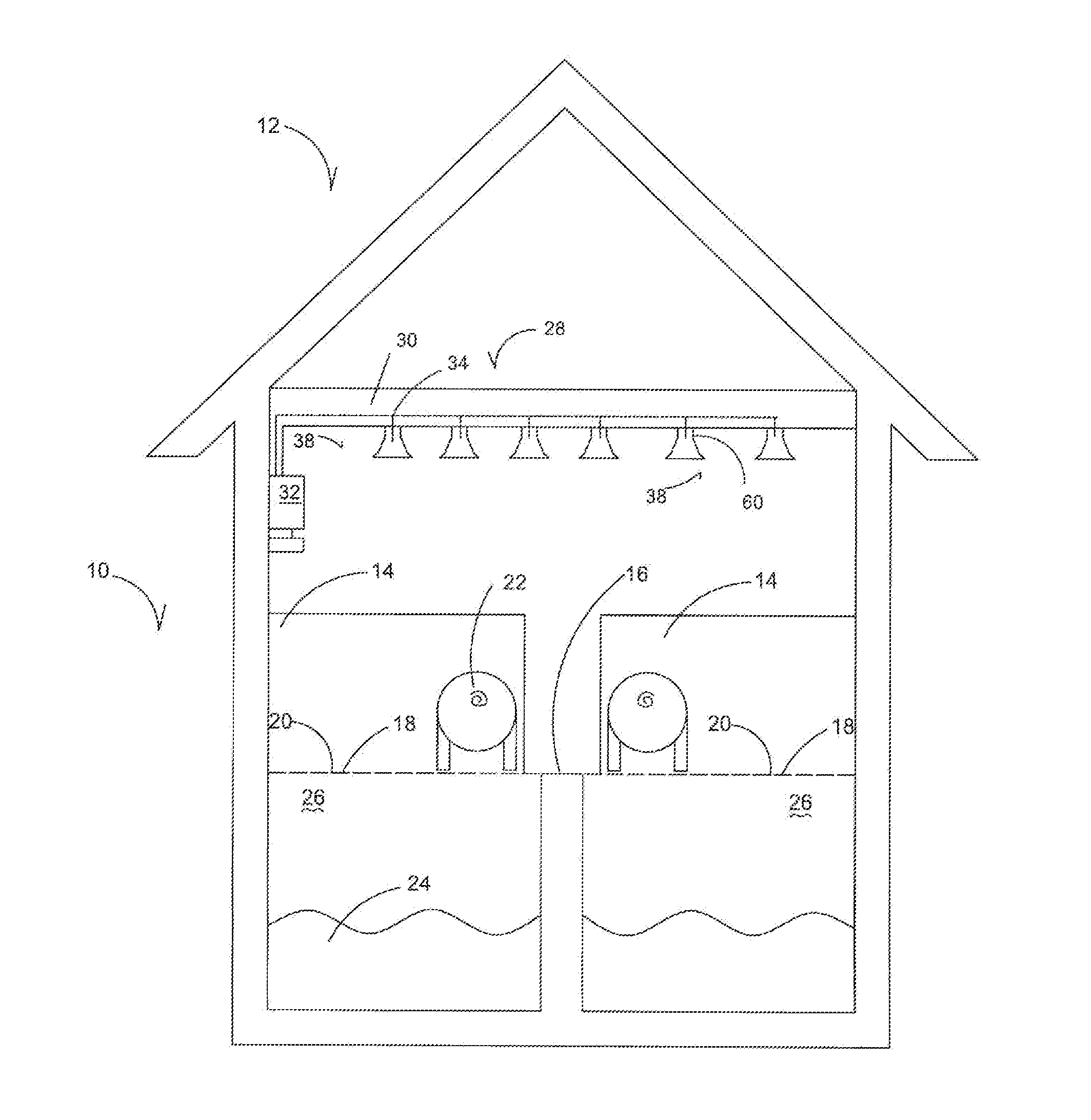
[0011] FIG. 1 is a cutaway side plan view of a dwelling for livestock.
[0012] FIG. 2 is a side plan view of a lighting assembly for a dwelling for livestock.
[0013] FIG. 3 is a side front perspective view of a lighting assembly for a dwelling for livestock.
[0014] FIG. 4 is a top perspective view of a lighting assembly for a dwelling for livestock.
[0015] FIG. 5 is a schematic diagram of electric components for a lighting assembly for a dwelling for livestock.
[0016] FIG. 6 is a schematic diagram of a lighting system for a dwelling for livestock.
DETAILED DESCRIPTION OF A PREFERRED EMBODIMENT OF THE INVENTION
[0017] The figures show a swine facility 10 that includes a dwelling 12 such as a barn or hog containment facility. The dwelling 12 has a plurality of containment units 14 such as pens, stalls and the like. The floor 16 of the containment units 14 consist of a plurality of slat elements 18 that sit in paralleled spaced relation to one another to form a plurality of openings 20 between consecutive slat elements 18. In one embodiment the slat elements 18 are angled or slanted with one end higher than the other to cause a downward slope toward an opening 20 in the floor 16. In this manner when a swine 22 steps on or rolls on feces 24 the feces 24 is pushed through the openings 20 below the floor 16. Similarly, during wash down of the containment units 16 the feces is power sprayed and the water and feces go through the openings 20 beneath the floor and into a reservoir 26.
[0018] The figures also show a lighting system 28 that in one embodiment includes a plurality of electrical conduit bodies 30 that receive and electrical input from an electrical source 32. The electrical conduit bodies 30 house wiring 34 that extend to provide an electric excitation signal to different areas in the dwelling. In one embodiment the wiring is electrically connected to a socket 36 to receive a lighting assembly 38.
[0019] The lighting assembly 38 includes a base 40 having electrical conducting elements 42 therein that threadably and electrically connects within the socket 36 as is known in the art. The base 40 is either threadably received or compression fit onto a frustroconally shaped body 44 having a hollow interior and a sidewall 48 that extends outwardly and away from a first end 50 having a first diameter to a second end 52 having a second diameter greater than the first diameter. In this manner when waste or feces or water is sprayed on the body 44 the material flows downwardly and off the assembly 38. At the second end is a ring element 54 that is of size and shape to engage a sealing element 56 that in a preferred embodiment is made from an elastic material that expands upon compression. The sealing element 56 is secured between the ring element 54 and heat sink 58 to provide a water tight seal therebetween. In this manner electrical wiring 60 is electrically connected to the conductive body through the body 44 and heat sink within a water tight assembly 38.
[0020] In an alternative embodiment a socket 36 is not presented and instead the wiring is directly provided. In this embodiment the body 44 with the base 40 are not provided and instead the electrical wiring 60 disposed through the heat sink is directly or hard wired to the wiring 34 of the conduit to provide a direct electrical connection. The heat sink is then threadably and/or sealing connected to the conduit again to provide a water tight seal to prevent water from being within the interior of the heat sink 58 and being exposed to the electrical wiring 60.
[0021] The heat sink 58 in a preferred embodiment is made of a plastic material and has a plurality of fin elements 62 that assist in conveying heat through the heat sink 58. The heat sink 58 extends from a first end 64 adjacent the conduit bodies 30 that receives the sealing element 56 in one embodiment and is sealed to a conduit body 30 in another to second end 66. The second end 66 is secured to a diffusion element 68 that has a frustroconical shape having a sidewall 69 that extends from a first end 70 outwardly and downwardly from the heat sink 58 to an open second end 72 having a diameter slightly greater than the diameter of the first end 70 and terminating in a lip element 74. By being sloped at an angle and downwardly, again, water, feces and other materials often known to swine facilities 10 flow off the diffusion element 68, yet the lip element 74 keeps a robust design to withstand the harsh environment.
[0022] A substrate 76 is also secured to the second end 66 of the heat sink 58 and in one embodiment has a generally round shape. The substrate also in one embodiment is a printed circuit board. FIG. 4 shows the substrate 76 having driving circuitry 78. The circuitry is similar to that taught in U.S. Pat. No. 8,373,363 entitled Reduction of Harmonic Distortion for LED Loads, by Z. Grajcar and issued on Feb. 12, 2013 and U.S. patent application entitled "Color Temperature Shift Control for Dimmable AC LED Lighting," Ser. No. 12/824,215, which was filed by Z. Grajcar on Jun. 27, 2010, the entire contents of each of which are incorporated herein by reference.
[0023] The circuitry 78 of the present invention includes a rectifying device 80 that receives current from an AC source 82 and includes a first group of light emitting diodes 84 arranged in series with a second group of light emitting diodes 86, both of which comprise diodes emitting white light. A third group of light emitting diodes 88 comprising diodes emitting red light are presented in parallel to the first and second groups of diodes 84 and 86. Red light emitted is considered any light having a wavelength approximately between 620 nm and 780 nm. Alternatively light emitting diodes having providing blue light, or having a wavelength approximately between 400 nm and 500 nm could be used without falling outside the scope of this invention. A bypass path 90 is presented with a first impedance element 92, that in one embodiment is a transistor. In a preferred embodiment the first impedance element 92 is a depletion MOSFET, though a p-channel MOSFET, n-channel MOSFET or the like can be used without falling outside the scope of this disclosure, even if an additional transistor is required for functionality purposes. A first resistor 94 is also provided to control the flow of current through the first impedance element 92 to provide smooth and continuous current flow.
[0024] A second bypass path 96 is also provided with a second impedance element 98 that similarly in one embodiment is a depletion MOSFET. Similar to the first bypass path 90 the second bypass path 96 utilizes a second resistor 100 again to control the impedance element 98. Similarly also, a third bypass path 102 is provided between the third group of light emitting diodes 88 and first and second groups of light emitting diodes 84 and 86. Again, this bypass path 102 utilizes a third impedance element 104 and third resistor 106 to provide similar functionality as the other bypass paths. In this manner when a dimming device 108 is electrically connected to the circuit and the voltage begins dropping, current flow to the first group of diodes 84 drops first, dimming out the first group of white diodes. Then as dimming continues and a threshold current is reached the second group of light emitting diodes 86 begin to dim. Thus, again white light is slowly dimmed and eliminated from the output light. In this manner only the third group of light emitting diodes 88 that are red remain providing light. A supplemental resistor 109 optionally is provided to limit current in the system and to improve efficiencies.
[0025] Therefore the assembly dims to produce a red light. Consequently, with a programmable dimming device the lighting assembly 38 can provide a combination of white and red light throughout a 24 hour period to optimize swine characteristics.
[0026] A lens element 110 is secured to the heat sink 58, diffusion element 68 or both. In one embodiment fastening elements 112 are utilized to provide the connection. In particular the lens element 110 is secured to provide a water tight seal so that water cannot encroach the interior of the assembly 38.
[0027] In operation a plurality of light assemblies 38 are installed into a facility 10 and electrically connected to a dimming device 108 having a programmable timer 113. The assembly is connected within the barn either directly or the body 44 can be attached to provide a retro fit if needed instead of a hard wire connection. In this manner the assembly 38 is modular in design.
[0028] The programmable timer can then be programmed to provide maximum lighting during times when workers or humans are present in the barn. Because swine do not detect red wavelength light, the red component of the light assembly provides additional intensity and lumens making it easier for workers to see and lighting up the facilities 10. Meanwhile, because the swine do not detect this light there are no harmful effects on the swine. Then as the day goes on the white light emitting diodes are dimmed out to present red light. Because the swine cannot detect the light they perceive this time as dark, allowing them to sleep, rest and provide optimum weight gain and feed consumption. Meanwhile, if people still need to be within the facility a light source allowing them to see and work is still provided.
[0029] Alternatively, the programmable timer can be adjusted so that more or less light is provided throughout a day to indicate to the swine that a particular season is provided. In this manner the behavior of the swine is manipulated enhancing farrowing, activity or other desired behavior. Thus, the lighting assembly 38 is used to manipulate both psychological and physiological characteristics of the swine to optimize growth, breeding and production of the swine. While presented in a preferred embodiment with red light emitting diodes, as indicated in the disclosure, blue light emitting diodes could similarly be used with the driving circuitry 78 and used to attract the swine to food or influence other swine behaviors without falling outside the scope of this disclosure.
[0030] When wash down of the facilities 10 is required the assemblies 38 are sprayed with water from a power washer, hose or other water supply. The water then envelopes any dirt, dust, feces or other containments and the frustroconical sections of the assembly 38 allow for easy removal of the containments keeping the assembly 38 and facility clean and sanitary. Because of the water tight seals water does not enter the interior of the assembly 38 again ensuring long life of the assembly 38. Thus, at the very least, all of the stated objects have been met.
* * * * *
D00000
D00001
D00002
D00003
D00004
D00005
D00006
XML
uspto.report is an independent third-party trademark research tool that is not affiliated, endorsed, or sponsored by the United States Patent and Trademark Office (USPTO) or any other governmental organization. The information provided by uspto.report is based on publicly available data at the time of writing and is intended for informational purposes only.
While we strive to provide accurate and up-to-date information, we do not guarantee the accuracy, completeness, reliability, or suitability of the information displayed on this site. The use of this site is at your own risk. Any reliance you place on such information is therefore strictly at your own risk.
All official trademark data, including owner information, should be verified by visiting the official USPTO website at www.uspto.gov. This site is not intended to replace professional legal advice and should not be used as a substitute for consulting with a legal professional who is knowledgeable about trademark law.