Methods And Systems For The Industrial Internet Of Things
Cella; Charles Howard ; et al.
U.S. patent application number 16/185606 was filed with the patent office on 2019-06-06 for methods and systems for the industrial internet of things. The applicant listed for this patent is StrongForce IoT Portfolio 2016, LLC. Invention is credited to Charles Howard Cella, Mehul Desai, Gerald William Duffy, JR., Jeffrey P. McGuckin.
| Application Number | 20190174207 16/185606 |
| Document ID | / |
| Family ID | 66658251 |
| Filed Date | 2019-06-06 |


View All Diagrams
| United States Patent Application | 20190174207 |
| Kind Code | A1 |
| Cella; Charles Howard ; et al. | June 6, 2019 |
METHODS AND SYSTEMS FOR THE INDUSTRIAL INTERNET OF THINGS
Abstract
A monitoring system for data collection in an industrial environment includes a data acquisition circuit that determines detection values received from input sensors, a multiplexor (MUX) having a number of inputs corresponding to a subset of the detection values, and a MUX control circuit that provides logical control of the MUX based on the subset of the detection values, including control of a correspondence of MUX inputs to detection values, and adaptive scheduling of select lines. The system includes a data analysis circuit that receives an output from the MUX and determines a component health status, and an analysis response circuit that responds to the component health status.
| Inventors: | Cella; Charles Howard; (Pembroke, MA) ; Desai; Mehul; (Oak Brook, IL) ; Duffy, JR.; Gerald William; (Philadelphia, PA) ; McGuckin; Jeffrey P.; (Philadelphia, PA) | ||||||||||
| Applicant: |
|
||||||||||
|---|---|---|---|---|---|---|---|---|---|---|---|
| Family ID: | 66658251 | ||||||||||
| Appl. No.: | 16/185606 | ||||||||||
| Filed: | November 9, 2018 |
Related U.S. Patent Documents
| Application Number | Filing Date | Patent Number | ||
|---|---|---|---|---|
| PCT/US17/31721 | May 9, 2017 | |||
| 16185606 | ||||
| 62584099 | Nov 9, 2017 | |||
| 62333589 | May 9, 2016 | |||
| 62350672 | Jun 15, 2016 | |||
| 62412843 | Oct 26, 2016 | |||
| 62427141 | Nov 28, 2016 | |||
| Current U.S. Class: | 1/1 |
| Current CPC Class: | G08C 15/00 20130101; H04L 67/12 20130101; H04Q 9/00 20130101 |
| International Class: | H04Q 9/00 20060101 H04Q009/00; H04L 29/08 20060101 H04L029/08 |
Claims
1. A monitoring system for data collection in an industrial environment, the monitoring system comprising: a data acquisition circuit structured to interpret a plurality of detection values, each of the plurality of detection values corresponding to an input received from at least one of a plurality of input sensors; a multiplexor (MUX) having a plurality of inputs corresponding to a subset of the detection values; a MUX control circuit structured to interpret the subset of the plurality of detection values and provide as a result a logical control of the MUX and a correspondence of MUX input and detection values, wherein the logical control of the MUX comprises an adaptive scheduling of one or more select lines; a data analysis circuit structured to receive an output from the MUX and data corresponding to the logical control of the MUX resulting in a component health status; and an analysis response circuit adapted to perform at least one operation in response to the component health status, wherein the plurality of input sensors includes at least two sensors selected from the group consisting of a temperature sensor, a load sensor, a vibration sensor, an acoustic wave sensor, a heat flux sensor, an infrared sensor, an accelerometer, a tri-axial vibration sensor and a tachometer.
2. The monitoring system of claim 1, wherein at least one of the plurality of detection values corresponds to a fusion of two or more input sensors representing a virtual sensor.
3. The monitoring system of claim 1, wherein the system further comprises a data storage circuit adapted to store at least one of a plurality of component specifications and an anticipated component state information and buffer a subset of the plurality of detection values for a predetermined length of time.
4. The monitoring system of claim 1, wherein the system further comprises a data storage circuit adapted to store at least one of component specifications and an anticipated component state information and buffer an output of the multiplexor and data corresponding to the logical control of the MUX for a predetermined length of time.
5. The monitoring system of claim 1, wherein the data analysis circuit comprises at least one of a peak detection circuit, a phase detection circuit, a bandpass filter circuit, a frequency transformation circuit, a frequency analysis circuit, a phase lock loop circuit, a torsional analysis circuit, and a bearing analysis circuit.
6. The monitoring system of claim 3, wherein the at least one operation further comprises storing additional data in the data storage circuit.
7. The monitoring system of claim 1, wherein the at least one operation comprises at least one of enabling or disabling one or more portions of the MUX.
8. The monitoring system of claim 1, wherein the at least one operation comprises causing the MUX control circuit to alter the logical control of the MUX and the correspondence of MUX input and detection values.
9. A monitoring system for data collection in an industrial environment, the monitoring system comprising: a data acquisition circuit structured to interpret a plurality of detection values, each of the plurality of detection values corresponding to input received from at least one of a plurality of input sensors; at least two multiplexors (MUX), each having inputs corresponding to a subset of the detection values and each providing a data stream as output; a MUX control circuit structured to interpret a subset of the plurality of detection values and provide the logical control of the at least two MUX and control of a correspondence of MUX input and detected values as a result, wherein the logic control of the MUX comprises an adaptive scheduling of one or more select lines; a data analysis circuit structured to receive the data stream from at least one of the at least two MUX and data corresponding to the logic control of the MUX resulting in a component health status; and an analysis response circuit structured to perform at least one operation in response to the component health status, wherein the plurality of sensors includes at least two sensors selected from the group consisting of a temperature sensor, a load sensor, a vibration sensor, an acoustic wave sensor, a heat flux sensor, an infrared sensor, an accelerometer, a tri-axial vibration sensor and a tachometer.
10. The monitoring system of claim 9, wherein at least one of the plurality of detection values corresponds to a fusion of two or more input sensors representing a virtual sensor.
11. The monitoring system of claim 9, wherein the system further comprises a data storage circuit adapted to store at least one of a plurality of component specifications and an anticipated component state information and buffer a subset of the plurality of detection values for a predetermined length of time.
12. The monitoring system of claim 9, wherein the system further comprises a data storage circuit adapted to store at least one of component specifications and an anticipated component state information and buffer an output of the multiplexor and data corresponding to the logical control of the MUX for a predetermined length of time.
13. The monitoring system of claim 9, wherein the data analysis circuit comprises at least one of a peak detection circuit, a phase detection circuit, a bandpass filter circuit, a frequency transformation circuit, a frequency analysis circuit, a phase lock loop circuit, a torsional analysis circuit, and a bearing analysis circuit.
14. The monitoring system of claim 11, wherein the at least one operation further comprises storing additional data in the data storage circuit.
15. The monitoring system of claim 9, wherein the at least one operation comprises at least one of enabling or disabling one or more portions of the multiplexers.
16. The monitoring system of claim 9, wherein the at least one operation comprises causing the MUX control circuit to alter the logical control of the MUX and the correspondence of MUX input and detection values.
17. A system for data collection in an industrial environment having a self-sufficient data acquisition box for capturing and analyzing data in an industrial process, the system comprising: a data circuit for analyzing a plurality of sensor inputs from one or more sensors; and a network control circuit for sending and receiving information related to the sensor inputs to an external system; wherein the system provides sensor data to one or more similarly configured systems and wherein the data circuit dynamically reconfigures a route by which data is sent based, at least in part, on a number of other devices requesting the information.
18. The system of claim 17, wherein the system further comprises a plurality of network communication interfaces.
19. The system of claim 18, wherein the network control circuit bridges another similarly configured system from a first network to a second network by utilizing the plurality of network communication interfaces.
20. The system of claim 19, wherein the other similarly configured system has one or more operational characteristics that differ from one or more operational characteristics of the system.
21. The system of claim 20, wherein the one or more operational characteristics of the similarly configured system are selected from the list consisting of a power, a storage, a network connectivity, a proximity, a reliability and a duty cycle.
22. The system of claim 17, wherein the network control circuit is adapted to implement a network of similarly configured systems using an intercommunication protocol selected from the list consisting of a multi-hop, a mesh, a serial, a parallel, a ring, a real-time and a hub-and-spoke.
23. The system of claim 17, wherein the system is adapted to continuously provide a single copy of its information to another similarly configured system and direct one or more entities requesting the information to the other similarly configured system.
24. The system of claim 17, wherein the system is adapted to store a summary of the information.
25. The system of claim 24, wherein the system is adapted to store the summary after a configurable time period.
26. A method for data collection in an industrial production environment, the method comprising: analyzing with a processor a plurality of sensor inputs, wherein the plurality of sensor inputs is configured to sense a health status of a component of at least one target system; sampling with the processor data received from at least one of the plurality of sensor inputs; and self-organizing with the processor at least one of: (i) a storage operation of the data; (ii) a collection operation of one or more sensors adapted to provide the plurality of sensor inputs, and (iii) a selection operation of the plurality of sensor inputs.
27. The method of claim 26, wherein the plurality of sensor inputs is further configured to sense at least one of: an operational mode of the target system, a fault mode of the target system, or a health status of the target system.
28. A system for data collection in an industrial production environment, the system comprising: one or more sensors adapted to provide a plurality of sensor inputs, wherein the one or more sensors are configured to sense a health status of a component of at least one target system; and a data collector comprising a processor and adapted to analyze the plurality of sensor inputs, sample data received from at least one of the plurality of sensor inputs and self-organize at least one of: (i) a storage operation of the data; (ii) a collection operation of one or more sensors adapted to provide the plurality of sensor inputs, and (iii) a selection operation of the plurality of sensor inputs.
29. The system of claim 28, wherein at least one of the one or more sensors forms a part of the data collector.
30. The system of claim 28, wherein at least one of the one or more sensors is external to the data collector.
31. The system of claim 28, wherein the one or more sensor inputs are configured to sense at least one of: an operational mode of the target system, a fault mode of the target system, or a health status of the target system.
32. A method comprising: analyzing with a processor a plurality of sensor inputs; sampling with the processor data received from at least one of the plurality of sensor inputs at a first frequency; and self-organizing with the processor a selection operation of the plurality of sensor inputs, wherein the selection operation comprises: receiving a signal relating to at least one condition of an industrial environment; and based, at least in part, on the signal, changing at least one of the sensor inputs analyzed and sampling the data received from at least one of the plurality of sensor inputs at a second frequency.
33. The method of claim 32, wherein the at least one condition of the industrial environment is a signal-to-noise ratio of the sampled data.
34. The method of claim 32, wherein the selection operation further comprises identifying a target signal to be sensed.
35. The method of claim 34, wherein the selection operation further comprises: identifying one or more non-target signals in a same frequency band as the target signal to be sensed; and based, at least in part, on the identified one or more non-target signals, changing at least one of the sensor inputs analyzed and a frequency of the sampling.
36. The method of claim 34, wherein the selection operation further comprises: identifying other data collectors sensing in a same signal band as the target signal to be sensed; and based on the identified other data collectors, changing at least one of the sensor inputs analyzed and a frequency of the sampling.
37. The method of claim 36, wherein the selection operation further comprises: identifying a level of activity of a target associated with the target signal to be sensed; and based, at least in part, on the identified level of activity, changing at least one of the sensor inputs analyzed and a frequency of the sampling.
38. The method of claim 36, wherein the selection operation further comprises: receiving data indicative of one or more environmental conditions near a target associated with the target signal; comparing the received one or more environmental conditions of the target with past environmental conditions near the target or another target similar to the target; and based, at least in part, on the comparison, changing at least one of the sensor inputs analyzed and a frequency of the sampling.
39. The method of claim 38, wherein the selection operation further comprises transmitting at least a portion of the received sampling data to another data collector according to a predetermined hierarchy of data collection.
40. A method for data collection in an industrial environment having self-organization functionality, comprising: analyzing at a data collector a plurality of sensor inputs from one or more sensors, wherein at least one of the plurality of sensor inputs corresponds to a vibration sensor providing frequency data corresponding to a component of the industrial environment; sampling data received from the plurality of sensor inputs; and self-organizing at least one of: (i) a storage operation of the data; (ii) a collection operation of sensors that provide the plurality of sensor inputs, and (iii) a selection operation of the plurality of sensor inputs, wherein the selection operation comprises: receiving a signal relating to at least one condition of the component of the industrial environment; and based, at least in part, on the signal, changing a frequency of the sampling of the one of the plurality of sensor inputs corresponding to the vibration sensor.
41. The method of claim 40, further comprising: receiving data indicative of at least one condition of the industrial environment in proximity to the component of the industrial environment; transmitting at least a portion of the received sampled data to another data collector according to a predetermined hierarchy of data collection; receiving feedback via a network connection relating to a quality or sufficiency of the transmitted data; analyzing the received feedback, and based, at least in part, on the analysis of the received feedback, changing at least one of: the sensor inputs analyzed, the frequency of sampling, the data stored, and the data transmitted.
42. The method of claim 41, wherein the at least one condition of the industrial environment is a signal-to-noise ratio of the sampled data.
43. The method of claim 40, wherein at least one of the one or more sensors forms a part of the data collector.
44. The method of claim 40, wherein at least one of the one or more sensors is external to the data collector.
45. The method of claim 40, wherein the vibration sensor is configured to sense at least one of: an operational mode, a fault mode, or a health status of the component of the industrial environment.
46. A method for data collection in an industrial environment having self-organization functionality, comprising: analyzing at a data collector a plurality of sensor inputs from one or more sensors; sampling data received from the sensor inputs; and self-organizing at least one of: (i) a storage operation of the data; (ii) a collection operation of sensors that provide the plurality of sensor inputs, and (iii) a selection operation of the plurality of sensor inputs, wherein the selection operation comprises: identifying a target signal to be sensed; receiving a signal relating to at least one condition of the industrial environment, based, at least in part, on the signal, changing at least one of the sensor inputs analyzed and a frequency of the sampling; receiving data indicative of environmental conditions near a target associated with the target signal; transmitting at least a portion of the received sampling data to another data collector according to a predetermined hierarchy of data collection; receiving feedback via a network connection relating to one or more yield metrics of the transmitted data; analyzing the received feedback, and based on the analysis of the received feedback, changing at least one of the sensor inputs analyzed, the frequency of sampling, the data stored, and the data transmitted.
47. The method of claim 46, wherein the at least one condition of the industrial environment is a signal-to-noise ratio of the sampled data.
48. The method of claim 46, wherein at least one of the one or more sensors forms a part of the data collector.
49. The method of claim 46, wherein at least one of the one or more sensors is external to the data collector.
50. The method of claim 46, wherein the plurality of sensor inputs is configured to sense at least one of an operational mode, a fault mode and a health status of at least one target system.
51. A method for data collection in an industrial environment having self-organization functionality, comprising: analyzing at a data collector a plurality of sensor inputs from one or more sensors; sampling data received from the sensor inputs; and self-organizing at least one of: (i) a storage operation of the data; (ii) a collection operation of sensors that provide the plurality of sensor inputs, and (iii) a selection operation of the plurality of sensor inputs, wherein the selection operation comprises: identifying a target signal to be sensed, receiving a signal relating to at least one condition of the industrial environment, based, at least in part, on the signal, changing at least one of the sensor inputs analyzed and a frequency of the sampling, receiving data indicative of environmental conditions near a target associated with the target signal, transmitting at least a portion of the received sampling data to another data collector according to a predetermined hierarchy of data collection, receiving feedback via a network connection relating to a quality or sufficiency of the transmitted data, analyzing the received feedback, and based, at least in part, on the analysis of the received feedback, executing a dimensionality reduction algorithm on the sensed data.
52. The method of claim 51, wherein the dimensionality reduction algorithm is one or more of a Decision Tree, a Random Forest, a Principal Component Analysis, a Factor Analysis, a Linear Discriminant Analysis, Identification based on correlation matrix, a Missing Values Ratio, a Low Variance Filter, a Random Projection, a Nonnegative Matrix Factorization, a Stacked Auto-encoder, a Chi-square or Information Gain, a Multidimensional Scaling, a Correspondence Analysis, a Factor Analysis, a Clustering, and a Bayesian Models.
53. The method of claim 51, wherein the dimensionality reduction algorithm is performed at the data collector.
54. The method of claim 51, wherein executing the dimensionality reduction algorithm comprises sending the sensed data to a remote computing device.
55. The method of claim 51, wherein the at least one condition of the industrial environment is a signal-to-noise ratio of the sampled data.
56. The method of claim 51, wherein at least one of the one or more sensors forms a part of the data collector.
57. The method of claim 51, wherein at least one of the one or more sensors is external to the data collector.
58. The method of claim 51, wherein the plurality of sensor inputs is configured to sense at least one of an operational mode, a fault mode and a health status of at least one target system.
59. A system for self-organizing collection and storage of data collection in a power generation environment, the system comprising: a data collector for handling a plurality of sensor inputs from one or more sensors in the power generation environment, wherein the plurality of sensor inputs is configured to sense at least one of an operational mode, a fault mode, and a health status of at least one target system of the power generation environment; and a self-organizing system for self-organizing at least one of (i) a storage operation of the data; (ii) a data collection operation of the sensors that provide the plurality of sensor inputs, and (iii) a selection operation of the plurality of sensor inputs.
60. The system of claim 59, wherein the self-organizing system organizes a swarm of mobile data collectors to collect data from a plurality of target systems.
61. The system of claim 60, wherein each of the plurality of target systems further comprises at least one system selected from the group consisting of: a fuel handling system, a power source, a turbine, a generator, a gear system, an electrical transmission system, and a transformer.
62. The system of claim 59, wherein the system further comprises an intermittently available network, and wherein the self-organizing system is configured to perform the self-organizing based on an impeded network connectivity of the intermittently available network.
63. The system of claim 59, wherein the self-organizing system generates a storage specification for organizing storage of the data, the storage specification specifying data for local storage in the power generation environment and specifying data for streaming via a network connection from the power generation environment.
64. A system for self-organizing collection and storage of data collection in an energy source extraction environment, the system comprising: a data collector for handling a plurality of sensor inputs from sensors in the energy extraction environment, wherein the plurality of sensor inputs is configured to sense at least one of an operational mode, a fault mode, and a health status of at least one target system of the energy extraction environment; and a self-organizing system for self-organizing at least one of (i) a storage operation of the data; (ii) a data collection operation of the sensors that provide the plurality of sensor inputs, and (iii) a selection operation of the plurality of sensor inputs.
65. The system of claim 64, wherein the self-organizing system organizes a swarm of mobile data collectors to collect data from a plurality of target systems.
66. The system of claim 65, wherein each of the plurality of target systems further comprises at least one system selected from the group consisting of: a hauling system, a lifting system, a drilling system, a mining system, a digging system, a boring system, a material handling system, a conveyor system, a pipeline system, a wastewater treatment system, and a fluid pumping system.
67. The system of claim 64, wherein the system further comprises an intermittently available network, and wherein the self-organizing system is configured to perform the self-organizing based on an impeded network connectivity of the intermittently available network.
68. The system of claim 66, wherein the energy source extraction environment is a coal mining environment.
69. The system of claim 66, wherein the energy source extraction environment is a metal mining environment.
70. The system of claim 66, wherein the energy source extraction environment is a mineral mining environment.
71. The system of claim 66, wherein the energy source extraction environment is an oil drilling environment.
72. The system of claim 66, wherein the self-organizing system generates a storage specification for organizing storage of the data, the storage specification specifying data for local storage in the energy extraction environment and specifying data for streaming via a network connection from the energy extraction environment.
73. A system for self-organizing collection and storage of data collection in a refining environment, the system comprising: a data collector for handling a plurality of sensor inputs from sensors in the refining environment, wherein the plurality of sensor inputs is configured to sense at least one of an operational mode, a fault mode and a health status of at least one target system; and a self-organizing system for self-organizing at least one of (i) a storage operation of the data; (ii) a data collection operation of the sensors that provide the plurality of sensor inputs, and (iii) a selection operation of the plurality of sensor inputs.
74. The system of claim 73, wherein the self-organizing system organizes a swarm of mobile data collectors to collect data from a plurality of target systems.
75. The system of claim 74, wherein the self-organizing system generates a storage specification for organizing the storage of the data, the storage specification specifying data for local storage in the refining environment and specifying data for streaming via a network connection from the refining environment.
76. The system of claim 73, wherein the target system comprises at least one system selected from the group consisting of: a power system, a pumping system, a mixing system, a reaction system, a distillation system, a fluid handling system, a heating system, a cooling system, an evaporation system, a catalytic system, a moving system, and a container system.
77. The system of claim 73, wherein the system further comprises an intermittently available network, and wherein the self-organizing system is configured to perform the self-organizing based on an impeded network connectivity of the intermittently available network.
78. The system of claim 77, wherein the refining environment is a chemical refining environment.
79. The system of claim 77, wherein the refining environment is a pharmaceutical refining environment.
80. The system of claim 77, wherein the refining environment is a biological refining environment.
81. The system of claim 77, wherein the refining environment is a hydrocarbon refining environment.
Description
CROSS-REFERENCE TO RELATED APPLICATIONS
[0001] This application claims the benefit of U.S. Provisional Pat. App. No. 62/584,099 (STRF-0020-P01), filed 9 Nov. 2017, entitled "Methods and Systems for the Industrial Internet of Things".
[0002] This application also is a bypass continuation-in-part of International Pat. App. No. PCT/US17/31721 (STRF-0001-WO), filed on 9 May 2017, published on 16 Nov. 2017 as WO 2017/196821, and entitled "Methods and Systems for the Industrial Internet of Things". International Pat. App. No. PCT/US17/31721 claims the benefit of: U.S. Provisional Pat. App. No. 62/333,589 (STRF-0001-P01), filed 9 May 2016, entitled "Strong Force Industrial IoT Matrix"; U.S. Provisional Pat. App. No. 62/350,672 (STRF-0001-P02), filed 15 Jun. 2016, entitled "Strategy for High Sampling Rate Digital Recording of Measurement Waveform Data as Part of an Automated Sequential List that Streams Long-Duration and Gap-Free Waveform Data to Storage for more flexible Post-Processing"; U.S. Provisional Pat. App. No. 62/412,843 (STRF-0001-P03), filed 26 Oct. 2016, entitled "Methods and Systems for the Industrial Internet of Things"; and U.S. Provisional Pat. App. No. 62/427,141 (STRF-0001-P04), filed 28 Nov. 2016, entitled "Methods and Systems for the Industrial Internet of Things".
[0003] All of the above applications are hereby incorporated by reference in their entirety.
BACKGROUND
1. Field
[0004] The present disclosure relates to methods and systems for data collection in industrial environments, as well as methods and systems for leveraging collected data for monitoring, remote control, autonomous action, and other activities in industrial environments.
2. Description of the Related Art
[0005] Heavy industrial environments, such as environments for large scale manufacturing (such as of aircraft, ships, trucks, automobiles, and large industrial machines), energy production environments (such as oil and gas plants, renewable energy environments, and others), energy extraction environments (such as mining, drilling, and the like), construction environments (such as for construction of large buildings), and others, involve highly complex machines, devices and systems and highly complex workflows, in which operators must account for a host of parameters, metrics, and the like in order to optimize design, development, deployment, and operation of different technologies in order to improve overall results. Historically, data has been collected in heavy industrial environments by human beings using dedicated data collectors, often recording batches of specific sensor data on media, such as tape or a hard drive, for later analysis. Batches of data have historically been returned to a central office for analysis, such as by undertaking signal processing or other analysis on the data collected by various sensors, after which analysis can be used as a basis for diagnosing problems in an environment and/or suggesting ways to improve operations. This work has historically taken place on a time scale of weeks or months, and has been directed to limited data sets.
[0006] The emergence of the Internet of Things (IoT) has made it possible to connect continuously to and among a much wider range of devices. Most such devices are consumer devices, such as lights, thermostats, and the like. More complex industrial environments remain more difficult, as the range of available data is often limited, and the complexity of dealing with data from multiple sensors makes it much more difficult to produce "smart" solutions that are effective for the industrial sector. A need exists for improved methods and systems for data collection in industrial environments, as well as for improved methods and systems for using collected data to provide improved monitoring, control, and intelligent diagnosis of problems and intelligent optimization of operations in various heavy industrial environments.
SUMMARY
[0007] Methods and systems are provided herein for data collection in industrial environments, as well as for improved methods and systems for using collected data to provide improved monitoring, control, and intelligent diagnosis of problems and intelligent optimization of operations in various heavy industrial environments. These methods and systems include methods, systems, components, devices, workflows, services, processes, and the like that are deployed in various configurations and locations, such as: (a) at the "edge" of the Internet of Things, such as in the local environment of a heavy industrial machine; (b) in data transport networks that move data between local environments of heavy industrial machines and other environments, such as of other machines or of remote controllers, such as enterprises that own or operate the machines or the facilities in which the machines are operated; and (c) in locations where facilities are deployed to control machines or their environments, such as cloud-computing environments and on-premises computing environments of enterprises that own or control heavy industrial environments or the machines, devices or systems deployed in them. These methods and systems include a range of ways for providing improved data include a range of methods and systems for providing improved data collection, as well as methods and systems for deploying increased intelligence at the edge, in the network, and in the cloud or premises of the controller of an industrial environment.
[0008] Methods and systems are disclosed herein for continuous ultrasonic monitoring, including providing continuous ultrasonic monitoring of rotating elements and bearings of an energy production facility.
[0009] Methods and systems are disclosed herein for cloud-based, machine pattern recognition based on fusion of remote, analog industrial sensors.
[0010] Methods and systems are disclosed herein for cloud-based, machine pattern analysis of state information from multiple analog industrial sensors to provide anticipated state information for an industrial system.
[0011] Methods and systems are disclosed herein for on-device sensor fusion and data storage for industrial IoT devices, including on-device sensor fusion and data storage for an Industrial IoT device, where data from multiple sensors is multiplexed at the device for storage of a fused data stream.
[0012] Methods and systems are disclosed herein for a self-organizing data marketplace for industrial IoT data, including a self-organizing data marketplace for industrial IoT data, where available data elements are organized in the marketplace for consumption by consumers based on training a self-organizing facility with a training set and feedback from measures of marketplace success.
[0013] Methods and systems are disclosed herein for self-organizing data pools, including self-organization of data pools based on utilization and/or yield metrics, including utilization and/or yield metrics that are tracked for a plurality of data pools.
[0014] Methods and systems are disclosed herein for training artificial intelligence ("AI") models based on industry-specific feedback, including training an AI model based on industry-specific feedback that reflects a measure of utilization, yield, or impact, where the AI model operates on sensor data from an industrial environment.
[0015] Methods and systems are disclosed herein for a self-organized swarm of industrial data collectors, including a self-organizing swarm of industrial data collectors that organize among themselves to optimize data collection based on the capabilities and conditions of the members of the swarm.
[0016] Methods and systems are disclosed herein for an industrial IoT distributed ledger, including a distributed ledger supporting the tracking of transactions executed in an automated data marketplace for industrial IoT data.
[0017] Methods and systems are disclosed herein for a self-organizing collector, including a self-organizing, multi-sensor data collector that can optimize data collection, power and/or yield based on conditions in its environment.
[0018] Methods and systems are disclosed herein for a network-sensitive collector, including a network condition-sensitive, self-organizing, multi-sensor data collector that can optimize based on bandwidth, quality of service, pricing and/or other network conditions.
[0019] Methods and systems are disclosed herein for a remotely organized universal data collector that can power up and down sensor interfaces based on need and/or conditions identified in an industrial data collection environment.
[0020] Methods and systems are disclosed herein for a self-organizing storage for a multi-sensor data collector, including self-organizing storage for a multi-sensor data collector for industrial sensor data.
[0021] Methods and systems are disclosed herein for a self-organizing network coding for a multi-sensor data network, including self-organizing network coding for a data network that transports data from multiple sensors in an industrial data collection environment.
[0022] Methods and systems are disclosed herein for a haptic or multi-sensory user interface, including a wearable haptic or multi-sensory user interface for an industrial sensor data collector, with vibration, heat, electrical and/or sound outputs.
[0023] Methods and systems are disclosed herein for a presentation layer for augmented reality and virtual reality (AR/VR) industrial glasses, where heat map elements are presented based on patterns and/or parameters in collected data.
[0024] Methods and systems are disclosed herein for condition-sensitive, self-organized tuning of AR/VR interfaces based on feedback metrics and/or training in industrial environments.
[0025] In embodiments, a system for data collection, processing, and utilization of signals from at least a first element in a first machine in an industrial environment includes a platform including a computing environment connected to a local data collection system having at least a first sensor signal and a second sensor signal obtained from at least the first machine in the industrial environment. The system includes a first sensor in the local data collection system configured to be connected to the first machine and a second sensor in the local data collection system. The system further includes a crosspoint switch in the local data collection system having multiple inputs and multiple outputs including a first input connected to the first sensor and a second input connected to the second sensor. The multiple outputs include a first output and second output configured to be switchable between a condition in which the first output is configured to switch between delivery of the first sensor signal and the second sensor signal and a condition in which there is simultaneous delivery of the first sensor signal from the first output and the second sensor signal from the second output. Each of multiple inputs is configured to be individually assigned to any of the multiple outputs. Unassigned outputs are configured to be switched off producing a high-impedance state.
[0026] In embodiments, the first sensor signal and the second sensor signal are continuous vibration data about the industrial environment. In embodiments, the second sensor in the local data collection system is configured to be connected to the first machine. In embodiments, the second sensor in the local data collection system is configured to be connected to a second machine in the industrial environment. In embodiments, the computing environment of the platform is configured to compare relative phases of the first and second sensor signals. In embodiments, the first sensor is a single-axis sensor and the second sensor is a three-axis sensor. In embodiments, at least one of the multiple inputs of the crosspoint switch includes internet protocol, front-end signal conditioning, for improved signal-to-noise ratio. In embodiments, the crosspoint switch includes a third input that is configured with a continuously monitored alarm having a pre-determined trigger condition when the third input is unassigned to any of the multiple outputs.
[0027] In embodiments, the local data collection system includes multiple multiplexing units and multiple data acquisition units receiving multiple data streams from multiple machines in the industrial environment. In embodiments, the local data collection system includes distributed complex programmable hardware device ("CPLD") chips each dedicated to a data bus for logic control of the multiple multiplexing units and the multiple data acquisition units that receive the multiple data streams from the multiple machines in the industrial environment. In embodiments, the local data collection system is configured to provide high-amperage input capability using solid state relays. In embodiments, the local data collection system is configured to power-down at least one of an analog sensor channel and a component board.
[0028] In embodiments, the local data collection system includes an external voltage reference for an A/D zero reference that is independent of the voltage of the first sensor and the second sensor. In embodiments, the local data collection system includes a phase-lock loop band-pass tracking filter configured to obtain slow-speed revolutions per minute ("RPMs") and phase information. In embodiments, the local data collection system is configured to digitally derive phase using on-board timers relative to at least one trigger channel and at least one of the multiple inputs. In embodiments, the local data collection system includes a peak-detector configured to auto scale using a separate analog-to-digital converter for peak detection. In embodiments, the local data collection system is configured to route at least one trigger channel that is one of raw and buffered into at least one of the multiple inputs. In embodiments, the local data collection system includes at least one delta-sigma analog-to-digital converter that is configured to increase input oversampling rates to reduce sampling rate outputs and to minimize anti-aliasing filter requirements. In embodiments, the distributed CPLD chips each dedicated to the data bus for logic control of the multiple multiplexing units and the multiple data acquisition units includes as high-frequency crystal clock reference configured to be divided by at least one of the distributed CPLD chips for at least one delta-sigma analog-to-digital converter to achieve lower sampling rates without digital resampling.
[0029] In embodiments, the local data collection system is configured to obtain long blocks of data at a single relatively high-sampling rate as opposed to multiple sets of data taken at different sampling rates. In embodiments, the single relatively high-sampling rate corresponds to a maximum frequency of about forty kilohertz. In embodiments, the long blocks of data are for a duration that is in excess of one minute. In embodiments, the local data collection system includes multiple data acquisition units each having an onboard card set configured to store calibration information and maintenance history of a data acquisition unit in which the onboard card set is located. In embodiments, the local data collection system is configured to plan data acquisition routes based on hierarchical templates.
[0030] In embodiments, the local data collection system is configured to manage data collection bands. In embodiments, the data collection bands define a specific frequency band and at least one of a group of spectral peaks, a true-peak level, a crest factor derived from a time waveform, and an overall waveform derived from a vibration envelope. In embodiments, the local data collection system includes a neural net expert system using intelligent management of the data collection bands. In embodiments, the local data collection system is configured to create data acquisition routes based on hierarchical templates that each include the data collection bands related to machines associated with the data acquisition routes. In embodiments, at least one of the hierarchical templates is associated with multiple interconnected elements of the first machine. In embodiments, at least one of the hierarchical templates is associated with similar elements associated with at least the first machine and a second machine. In embodiments, at least one of the hierarchical templates is associated with at least the first machine being proximate in location to a second machine.
[0031] In embodiments, the local data collection system includes a graphical user interface ("GUI") system configured to manage the data collection bands. In embodiments, the GUI system includes an expert system diagnostic tool. In embodiments, the platform includes cloud-based, machine pattern analysis of state information from multiple sensors to provide anticipated state information for the industrial environment. In embodiments, the platform is configured to provide self-organization of data pools based on at least one of the utilization metrics and yield metrics. In embodiments, the platform includes a self-organized swarm of industrial data collectors. In embodiments, the local data collection system includes a wearable haptic user interface for an industrial sensor data collector with at least one of vibration, heat, electrical, and sound outputs.
[0032] In embodiments, multiple inputs of the crosspoint switch include a third input connected to the second sensor and a fourth input connected to the second sensor. The first sensor signal is from a single-axis sensor at an unchanging location associated with the first machine. In embodiments, the second sensor is a three-axis sensor. In embodiments, the local data collection system is configured to record gap-free digital waveform data simultaneously from at least the first input, the second input, the third input, and the fourth input. In embodiments, the platform is configured to determine a change in relative phase based on the simultaneously recorded gap-five digital waveform data. In embodiments, the second sensor is configured to be movable to a plurality of positions associated with the first machine while obtaining the simultaneously recorded gap-free digital waveform data. In embodiments, multiple outputs of the crosspoint switch include a third output and fourth output. The second, third, and fourth outputs are assigned together to a sequence of tri-axial sensors each located at different positions associated with the machine. In embodiments, the platform is configured to determine an operating deflection shape based on the change in relative phase and the simultaneously recorded gap-free digital waveform data.
[0033] In embodiments, the unchanging location is a position associated with the rotating shaft of the first machine. In embodiments, tri-axial sensors in the sequence of the tri-axial sensors are each located at different positions on the first machine but are each associated with different bearings in the machine. In embodiments, tri-axial sensors in the sequence of the tri-axial sensors are each located at similar positions associated with similar bearings but are each associated with different machines. In embodiments, the local data collection system is configured to obtain the simultaneously recorded gap-free digital waveform data from the first machine while the first machine and a second machine are both in operation. In embodiments, the local data collection system is configured to characterize a contribution from the first machine and the second machine in the simultaneously recorded gap-free digital waveform data from the first machine. In embodiments, the simultaneously recorded gap-free digital waveform data has a duration that is in excess of one minute.
[0034] In embodiments, a method of monitoring a machine having at least one shaft supported by a set of bearings includes monitoring a first data channel assigned to a single-axis sensor at an unchanging location associated with the machine. The method includes monitoring second, third, and fourth data channels each assigned to an axis of a three-axis sensor. The method includes recording gap-free digital waveform data simultaneously from all of the data channels while the machine is in operation and determining a change in relative phase based on the digital waveform data.
[0035] In embodiments, the tri-axial sensor is located at a plurality of positions associated with the machine while obtaining the digital waveform. In embodiments, the second, third, and fourth channels are assigned together to a sequence of tri-axial sensors each located at different positions associated with the machine. In embodiments, the data is received from all of the sensors simultaneously. In embodiments, the method includes determining an operating deflection shape based on the change in relative phase information and the waveform data. In embodiments, the unchanging location is a position associated with the shaft of the machine. In embodiments, the tri-axial sensors in the sequence of the tri-axial sensors are each located at different positions and are each associated with different bearings in the machine. In embodiments, the unchanging location is a position associated with the shaft of the machine. The tri-axial sensors in the sequence of the tri-axial sensors are each located at different positions and are each associated with different bearings that support the shaft in the machine.
[0036] In embodiments, the method includes monitoring the first data channel assigned to the single-axis sensor at an unchanging location located on a second machine. The method includes monitoring the second, the third, and the fourth data channels, each assigned to the axis of a three-axis sensor that is located at the position associated with the second machine. The method also includes recording gap-free digital waveform data simultaneously from all of the data channels from the second machine while both of the machines are in operation. In embodiments, the method includes characterizing the contribution from each of the machines in the gap-free digital waveform data simultaneously from the second machine.
[0037] In embodiments, the method includes planning data acquisition routes based on hierarchical templates associated with at least the first element in the first machine in the industrial environment. In embodiments, the local data collection system manages data collection bands that define a specific frequency band and at least one of a group of spectral peaks, a true-peak level, a crest factor derived from a time waveform, and an overall waveform derived from a vibration envelope. In embodiments, the local data collection system includes a neural net expert system using intelligent management of the data collection bands. In embodiments, the local data collection system creates data acquisition routes based on hierarchical templates that each include the data collection bands related to machines associated with the data acquisition routes. In embodiments, at least one of the hierarchical templates is associated with multiple interconnected elements of the first machine. In embodiments, at least one of the hierarchical templates is associated with similar elements associated with at least the first machine and a second machine. In embodiments, at least one of the hierarchical templates is associated with at least the first machine being proximate in location to a second machine.
[0038] Methods and systems described herein for industrial machine sensor data streaming, collection, processing, and storage may be configured to operate and integrate with existing data collection, processing and storage systems and may include a method for capturing a plurality of streams of sensed data from sensors deployed to monitor aspects of an industrial machine associated with at least one moving part of the machine; at least one of the streams containing a plurality of frequencies of data. The method may include identifying a subset of data in at least one of the plurality of streams that corresponds to data representing at least one predefined frequency. The at least one predefined frequency is represented by a set of data collected from alternate sensors deployed to monitor aspects of the industrial machine associated with the at least one moving part of the machine. The method may further include processing the identified data with a data processing facility that processes the identified data with an algorithm configured to be applied to the set of data collected from alternate sensors. Lastly, the method may include storing the at least one of the streams of data, the identified subset of data, and a result of processing the identified data in an electronic data set.
[0039] Methods and systems described herein for industrial machine sensor data streaming, collection, processing, and storage may be configured to operate and integrate with existing data collection, processing, and storage systems and may include a method for applying data captured from sensors deployed to monitor aspects of an industrial machine associated with at least one moving part of the machine. The data is captured with predefined lines of resolution covering a predefined frequency range and is sent to a frequency matching facility that identifies a subset of data streamed from other sensors deployed to monitor aspects of the industrial machine associated with at least one moving part of the machine. The streamed data includes a plurality of lines of resolution and frequency ranges. The subset of data identified corresponds to the lines of resolution and predefined frequency range. This method may include storing the subset of data in an electronic data record in a format that corresponds to a format of the data captured with predefined lines of resolution; and signaling to a data processing facility the presence of the stored subset of data. This method may, optionally, include processing the subset of data with at least one set of algorithms, models and pattern recognizers that corresponds to algorithms, models and pattern recognizers associated with processing the data captured with predefined lines of resolution covering a predefined frequency range.
[0040] Methods and systems described herein for industrial machine sensor data streaming, collection, processing, and storage may be configured to operate and integrate with existing data collection, processing and storage systems and may include a method for identifying a subset of streamed sensor data, the sensor data captured from sensors deployed to monitor aspects of an industrial machine associated with at least one moving part of the machine, the subset of streamed sensor data at predefined lines of resolution for a predefined frequency range, and establishing a first logical route for communicating electronically between a first computing facility performing the identifying and a second computing facility, wherein identified subset of the streamed sensor data is communicated exclusively over the established first logical route when communicating the subset of streamed sensor data from the first facility to the second facility. This method may further include establishing a second logical route for communicating electronically between the first computing facility and the second computing facility for at least one portion of the streamed sensor data that is not the identified subset. Additionally, this method may further include establishing a third logical route for communicating electronically between the first computing facility and the second computing facility for at least one portion of the streamed sensor data that includes the identified subset and at least one other portion of the data not represented by the identified subset.
[0041] Methods and systems described herein for industrial machine sensor data streaming, collection, processing, and storage may be configured to operate and integrate with existing data collection, processing and storage systems and may include a first data sensing and processing system that captures first data from a first set of sensors deployed to monitor aspects of an industrial machine associated with at least one moving part of the machine, the first data covering a set of lines of resolution and a frequency range. This system may include a second data sensing and processing system that captures and streams a second set of data from a second set of sensors deployed to monitor aspects of the industrial machine associated with at least one moving part of the machine, the second data covering a plurality of lines of resolution that includes the set of lines of resolution and a plurality of frequencies that includes the frequency range. The system may enable selecting a portion of the second data that corresponds to the set of lines of resolution and the frequency range of the first data, and processing the selected portion of the second data with the first data sensing and processing system.
[0042] Methods and systems described herein for industrial machine sensor data streaming, collection, processing, and storage may be configured to operate and integrate with existing data collection, processing and storage systems and may include a method for automatically processing a portion of a stream of sensed data. The sensed data is received from a first set of sensors deployed to monitor aspects of an industrial machine associated with at least one moving part of the machine. The sensed data is in response to an electronic data structure that facilitates extracting a subset of the stream of sensed data that corresponds to a set of sensed data received from a second set of sensors deployed to monitor the aspects of the industrial machine associated with the at least one moving part of the machine. The set of sensed data is constrained to a frequency range. The stream of sensed data includes a range of frequencies that exceeds the frequency range of the set of sensed data, the processing comprising executing an algorithm on a portion of the stream of sensed data that is constrained to the frequency range of the set of sensed data, the algorithm configured to process the set of sensed data.
[0043] Methods and systems described herein for industrial machine sensor data streaming, collection, processing, and storage may be configured to operate and integrate with existing data collection, processing and storage systems and may include a method for receiving first data from sensors deployed to monitor aspects of an industrial machine associated with at least one moving part of the machine. This method may further include detecting at least one of a frequency range and lines of resolution represented by the first data; receiving a stream of data from sensors deployed to monitor the aspects of the industrial machine associated with the at least one moving part of the machine. The stream of data includes: (1) a plurality of frequency ranges and a plurality of lines of resolution that exceeds the frequency range and the lines of resolution represented by the first data; (2) a set of data extracted from the stream of data that corresponds to at least one of the frequency range and the lines of resolution represented by the first data; and (3) the extracted set of data which is processed with a data processing algorithm that is configured to process data within the frequency range and within the lines of resolution of the first data.
[0044] An example monitoring system for data collection in an industrial environment includes a data acquisition circuit that interprets a number of detection values, each of the detection values corresponding to an input received from at least one of a number of input sensors; a multiplexor (MUX) having a number of inputs corresponding to a subset of the detection values; a MUX control circuit that interprets the subset of the detection values and provides, as a result, a logical control of the MUX and a correspondence of MUX input and detection values. The logical control of the MUX includes an adaptive scheduling of one or more select lines (e.g., MUX input to output relationships, MUX input to sensor relationships, and/or MUX output to downstream data collector relationships). The example system further includes a data analysis circuit that receives an output from the MUX and data corresponding to the logical control of the MUX resulting in a component health status, and an analysis response circuit adapted to perform at least one operation in response to the component health status. The input sensors include at least two sensors selected from: a temperature sensor, a load sensor, a vibration sensor, an acoustic wave sensor, a heat flux sensor, an infrared sensor, an accelerometer, a tri-axial vibration sensor, and/or and a tachometer.
[0045] Certain further aspects of an example system are described following, any one or more of which may be present in certain embodiments. An example system includes where one or more of the detection values correspond to a fusion of two or more input sensors representing a virtual sensor; a data storage circuit adapted to store at least one of a number of component specifications and/or an anticipated component state information, and to buffer a subset of the detection values for a predetermined length of time; a data storage circuit adapted to store at least one of component specifications and/or an anticipated component state information, and to buffer an output of the MUX and data corresponding to the logical control of the MUX for a predetermined length of time. An example system includes the data analysis circuit further including a peak detection circuit, a phase detection circuit, a bandpass filter circuit, a frequency transformation circuit, a frequency analysis circuit, a phase lock loop circuit, a torsional analysis circuit, and/or a bearing analysis circuit. An example system includes the operation as storing additional data in the data storage circuit, enabling or disabling one or more portions of the MUX, and/or causing the MUX control circuit to alter the logical control of the MUX and the correspondence of MUX input and detection values.
[0046] An example system for data collection in an industrial environment includes a data acquisition circuit that interprets a number of detection values, each of the number of detection values corresponding to input received from at least one of a number of input sensors; at least two multiplexors (MUXs), each having inputs corresponding to a subset of the detection values and each providing a data stream as output; a MUX control circuit that interprets a subset of the number of detection values and provides logical control of the MUXs, and control of a correspondence of MUX input and detected values as a result, where the logic control of the MUX comprise an adaptive scheduling of one or more select lines (e.g., MUX input to output relationships, MUX input to sensor relationships, and/or MUX output to downstream data collector relationships, and/or relationships between the MUXs). The example system further includes a data analysis circuit that receives the data stream from at least one of the MUXs and data corresponding to the logic control of the MUXs resulting in a component health status, and an analysis response circuit that performs at least one operation in response to the component health status. The input sensors include at least two sensors selected from: a temperature sensor, a load sensor, a vibration sensor, an acoustic wave sensor, a heat flux sensor, an infrared sensor, an accelerometer, a tri-axial vibration sensor, and/or and a tachometer.
[0047] Certain further aspects of an example system are described following, any one or more of which may be present in certain embodiments. An example system includes where at least one of the number of detection values corresponds to a fusion of two or more input sensors representing a virtual sensor; a data storage circuit adapted to store at least one of a number of component specifications and an anticipated component state information, and to buffer a subset of the number of detection values for a predetermined length of time; a data storage circuit adapted to store at least one of component specifications and an anticipated component state information and buffer an output of the multiplexor and data corresponding to the logical control of the MUX for a predetermined length of time; and/or where the data analysis circuit includes at least one of a peak detection circuit, a phase detection circuit, a bandpass filter circuit, a frequency transformation circuit, a frequency analysis circuit, a phase lock loop circuit, a torsional analysis circuit, and/or a bearing analysis circuit. An example system includes where the operation includes storing additional data in the data storage circuit; enabling or disabling one or more portions of at least one of the MUXs, and/or where the operation includes causing the MUX control circuit to alter the logical control of the MUXs and the correspondence of MUX input and detection values.
[0048] An example system for data collection in an industrial environment having a self-sufficient data acquisition box for capturing and analyzing data in an industrial process includes: a data circuit for analyzing a number of sensor inputs from one or more sensors; a network control circuit for sending and receiving information related to the sensor inputs to an external system, where the system provides sensor data to one or more similarly configured systems; and where the data circuit dynamically reconfigures a route by which data is sent based, at least in part, on a number of other devices requesting the information.
[0049] Certain further aspects of an example system are described following, any one or more of which may be present in certain embodiments. An example system includes a number of network communication interfaces; where the network control circuit bridges another similarly configured system from a first network to a second network via by utilizing the number of network communication interfaces; where the other similarly configured system has one or more operational characteristics that differ from one or more operational characteristics of the system; where the one or more operational characteristics of the similarly configured system are selected from the list consisting of a power, a storage, a network connectivity, a proximity, a reliability and a duty cycle; where the network control circuit is adapted to implement a network of similarly configured systems using an intercommunication protocol selected from the list consisting of a multi-hop, a mesh, a serial, a parallel, a ring, a real-time and a hub-and-spoke; where the system is adapted to continuously provide a single copy of its information to another similarly configured system and direct one or more entities requesting the information to the other similarly configured system; where the system is adapted to store a summary of the information; and/or where the system is adapted to store the summary after a configurable time period.
[0050] An example procedure for data collection in an industrial production environment includes: an operation to analyze, with a processor, a number of sensor inputs, where the sensor inputs are configured to sense a health status of a component of at least one target system; an operation to sample, with the processor, data received from at least one of the number of sensor inputs; and an operation to self-organize, with the processor, at least one of: (i) a storage operation of the data; (ii) a collection operation of one or more sensors adapted to provide the number of sensor inputs, and (iii) a selection operation of the number of sensor inputs. In certain further embodiments, the example procedure includes where the number of sensor inputs are further configured to sense at least one of: an operational mode of the target system, a fault mode of the target system, or a health status of the target system.
[0051] An example system for data collection in an industrial production environment includes: one or more sensors adapted to provide a number of sensor inputs, where the one or more sensors are configured to sense a health status of a component of at least one target system; and a data collector including a processor, and adapted to analyze the number of sensor inputs, sample data received from at least one of the number of sensor inputs, and to self-organize at least one of: (i) a storage operation of the data; (ii) a collection operation of one or more sensors adapted to provide the number of sensor inputs, and (iii) a selection operation of the number of sensor inputs. In certain further embodiments, the example system includes where at least one of the one or more sensors forms a part of the data collector; where at least one of the one or more sensors is external to the data collector; and/or where the one or more sensor inputs are configured to sense at least one of: an operational mode of the target system, a fault mode of the target system, or a health status of the target system.
[0052] An example procedure includes an operation to analyze, with a processor, a number of sensor inputs; an operation to sample, with the processor, data received from at least one of the number of sensor inputs at a first frequency, and an operation to self-organize, with the processor, a selection operation of the number of sensor inputs. An example selection operation includes: receiving a signal relating to at least one condition of an industrial environment; and based, at least in part, on the signal, changing at least one of the sensor inputs analyzed and sampling the data received from at least one of the number of sensor inputs at a second frequency.
[0053] Certain further aspects of an example procedure are described following, any one or more of which may be present in certain embodiments. An example procedure includes where the at least one condition of the industrial environment is a signal-to-noise ratio of the sampled data; where the selection operation further includes identifying one or more non-target signals in a same frequency band as the target signal to be sensed, and based, at least in part, on the identified one or more non-target signals, changing at least one of the sensor inputs analyzed and a frequency of the sampling; where the selection operation further includes identifying other data collectors sensing in a same signal band as the target signal to be sensed,; and based, at least in part, on the identified other data collectors, changing at least one of the sensor inputs analyzed and a frequency of the sampling; where the selection operation further includes identifying a level of activity of a target associated with the target signal to be sensed, and based, at least in part, on the identified level of activity, changing the at least one of the sensor inputs analyzed and a frequency of the sampling; where the selection operation further includes receiving data indicative of one or more environmental conditions near a target associated with the target signal, comparing the received one or more environmental conditions of the target with past environmental conditions near the target or another target similar to the target, and based, ate least in part, on the comparison, changing at least one of the sensor inputs analyzed and frequency of the sampling; and/or where the selection operation further includes transmitting at least a portion of the received sampling data to another data collector according to a predetermined hierarchy of data collection.
[0054] An example procedure for data collection in an industrial environment having self-organization functionality includes an operation to analyzed, at a data collector, a number of sensor inputs from one or more sensors, where at least one of the number of sensor inputs corresponds to a vibration sensor; an operation to provide frequency data corresponding to a component of the industrial environment; an operation to sample data received from the number of sensor inputs; and an operation to self-organize at least one of: (i) a storage operation of the data; (ii) a collection operation of sensors that provide the number of sensor inputs, and (iii) a selection operation of the number of sensor inputs. In certain embodiments, the selection operation further includes an operation to receive a signal relating to at least one condition of the component of the industrial environment, and based, at least in part, on the signal, an operation to change a frequency of the sampling of the one of the number of sensor inputs corresponding to the vibration sensor.
[0055] Certain further aspects of an example procedure are described following, any one or more of which may be present in certain embodiments. An example procedure further includes an operation to receive data indicative of at least one condition of the industrial environment in proximity to the component of the industrial environment, an operation to transmit at least a portion of the received sampled data to another collector according to a predetermined hierarchy of data collection; an operation to receive feedback via a network connection relating to a quality or sufficiency of the transmitted data; and operation to analyze the received feedback, based, at least in part, on the analysis of the received feedback, an operation to change at least one of: the sensor inputs analyzed, the frequency of the sampling, the data stored, and/or the data transmitted. An example procedure includes where the at least one condition of the industrial environment is a signal-to-noise ratio of the sampled data; where at least one of the one or more sensors forms a part of the data collector; where at least one of the one or more sensors is external to the data collector; and/or where the vibration sensor is configured to sense at least one of: an operational mode, a fault mode, or a health status of the component of the industrial environment.
[0056] An example procedure for data collection in an industrial environment having self-organization functionality includes an operation to analyze, at a data collector, a number of sensor inputs from one or more sensors; an operation to sample data received from the sensor inputs; and an operation to perform self-organizing including at least one of: (i) a storage operation of the data; (ii) a collection operation of sensors that provide the number of sensor inputs, and (iii) a selection operation of the number of sensor inputs. The example procedure includes the selection operation further including: an operation to identify a target signal to be sensed; an operation to receive a signal relating to at least one condition of the industrial environment, and based, at least in part, on the signal, an operation to change at least one of the sensor inputs analyzed and a frequency of the sampling; an operation to receive data indicative of environmental conditions near a target associated with the target signal; an operation to transmit at least a portion of the received sampling data to another data collector according to a predetermined hierarchy of data collection; an operation to receive feedback via a network connection relating to one or more yield metrics of the transmitted data; an operation to analyze the received feedback; and based on the analysis of the received feedback, an operation to change at least one of the sensor inputs analyzed, the frequency of sampling, the data stored, and the data transmitted. In certain embodiments, an example procedure includes where the at least one condition of the industrial environment is a signal-to-noise ratio of the sampled data; where at least one of the one or more sensors forms a part of the data collector; where at least one of the one or more sensors is external to the data collector; and/or where the number of sensor inputs are configured to sense at least one of an operational mode, a fault mode and a health status of at least one target system.
[0057] An example procedure for data collection in an industrial environment having self-organization functionality, comprising includes an operation to analyze, at a data collector, a number of sensor inputs from one or more sensors; an operation to sample data received from the sensor inputs; and an operation to self-organize at least one of: : (i) a storage operation of the data; (ii) a collection operation of sensors that provide the number of sensor inputs, and (iii) a selection operation of the number of sensor inputs. An example procedure further includes the selection operation including: an operation to identify a target signal to be sensed; an operation to receive a signal relating to at least one condition of the industrial environment; an operation based, at least in part, on the signal, to change at least one of the sensor inputs analyzed and a frequency of the sampling; an operation to receive data indicative of environmental conditions near a target associated with the target signal; an operation to transmit at least a portion of the received sampling data to another data collector according to a predetermined hierarchy of data collection; an operation to receive feedback via a network connection relating to a quality or sufficiency of the transmitted data; and an operation based, at least in part, on the analysis of the received feedback, to execute a dimensionality reduction algorithm on the sensed data.
[0058] Certain further aspects of an example procedure are described following, any one or more of which may be present in certain embodiments. An example procedure includes the dimensionality reduction algorithm including one or more of: a Decision Tree, a Random Forest, a Principal Component Analysis, a Factor Analysis, a Linear Discriminant Analysis, Identification based on correlation matrix, a Missing Values Ratio, a Low Variance Filter, a Random Projection, a Nonnegative Matrix Factorization, a Stacked Auto-encoder, a Chi-square or Information Gain, a Multidimensional Scaling, a Correspondence Analysis, a Factor Analysis, a Clustering, and/or a Bayesian Model. An example procedure includes: where the dimensionality reduction algorithm is performed at the data collector; where executing the dimensionality reduction algorithm comprises sending the sensed data to a remote computing device; where the at least one condition of the industrial environment is a signal-to-noise ratio of the sampled data; where at least one of the one or more sensors forms a part of the data collector; where at least one of the one or more sensors is external to the data collector; and/or where the number of sensor inputs are configured to sense at least one of an operational mode, a fault mode and a health status of at least one target system.
[0059] An example system for self-organizing collection and storage of data collection in a power generation environment includes a data collector for handling a number of sensor inputs from one or more sensors in the power generation environment, where the number of sensor inputs is configured to sense at least one of an operational mode, a fault mode, and a health status of at least one target system of the power generation environment; and a self-organizing system for self-organizing at least one of (i) a storage operation of the data; (ii) a data collection operation of the sensors that provide the number of sensor inputs, and (iii) a selection operation of the number of sensor inputs.
[0060] Certain further aspects of an example system are described following, any one or more of which may be present in certain embodiments. An example system includes where the self-organizing system organizes a swarm of mobile data collectors to collect data from a number of target systems; where each of the number of target systems further comprises at least one system such as a fuel handling system, a power source, a turbine, a generator, a gear system, an electrical transmission system, and/or a transformer; where the system further includes an intermittently available network, and where the self-organizing system is configured to perform the self-organizing based on an impeded network connectivity of the intermittently available network; and/or where the self-organizing system generates a storage specification for organizing storage of the data, the storage specification specifying data for local storage in the power generation environment and specifying data for streaming via a network connection from the power generation environment.
[0061] An example system for self-organizing collection and storage of data collection in an energy source extraction environment includes a data collector for handling a number of sensor inputs from sensors in the energy extraction environment, where the number of sensor inputs is configured to sense at least one of an operational mode, a fault mode, and a health status of at least one target system of the energy extraction environment; and a self-organizing system for self-organizing at least one of (i) a storage operation of the data; (ii) a data collection operation of the sensors that provide the number of sensor inputs, and (iii) a selection operation of the number of sensor inputs.
[0062] Certain further aspects of an example system are described following, any one or more of which may be present in certain embodiments. An example system includes where the self-organizing system organizes a swarm of mobile data collectors to collect data from a number of target systems; where each of the number of target systems further include a system such as a hauling system, a lifting system, a drilling system, a mining system, a digging system, a boring system, a material handling system, a conveyor system, a pipeline system, a wastewater treatment system, and/or a fluid pumping system; where the system further comprises an intermittently available network, and where the self-organizing system is configured to perform the self-organizing based on an impeded network connectivity of the intermittently available network; where the energy source extraction environment is a metal mining environment; where the energy source extraction environment is a coal mining environment; where the energy source extraction environment is a mineral mining environment; where the energy source extraction environment is an oil drilling environment; and/or where the self-organizing system generates a storage specification for organizing storage of the data, the storage specification specifying data for local storage in the energy extraction environment and specifying data for streaming via a network connection from the energy extraction environment.
[0063] An example system for self-organizing collection and storage of data collection in refining environment includes a data collector for handling a number of sensor inputs from sensors in the refining environment, where the number of sensor inputs is configured to sense at least one of an operational mode, a fault mode, and a health status of at least one target system of the refining environment; and a self-organizing system for self-organizing at least one of (i) a storage operation of the data; (ii) a data collection operation of the sensors that provide the number of sensor inputs, and (iii) a selection operation of the number of sensor inputs.
[0064] Certain further aspects of an example system are described following, any one or more of which may be present in certain embodiments. An example system includes where the self-organizing system organizes a swarm of mobile data collectors to collect data from a number of target systems; where the self-organizing system generates a storage specification for organizing the storage of the data, the storage specification specifying data for local storage in the refining environment and specifying data for streaming via a network connection from the refining environment; where each of the number of target systems further include a system such as a power system, a pumping system, a mixing system, a reaction system, a distillation system, a fluid handling system, a heating system, a cooling system, an evaporation system, a catalytic system, a moving system, and a container system; where the system further comprises an intermittently available network, and where the self-organizing system is configured to perform the self-organizing based on an impeded network connectivity of the intermittently available network; where the refining environment is a chemical refining environment; where the refining environment is a pharmaceutical environment; where the refining environment is a biological refining environment; and/or where the refining environment is a hydrocarbon refining environment.
BRIEF DESCRIPTION OF THE FIGURES
[0065] FIG. 1 through FIG. 5 are diagrammatic views that each depicts portions of an overall view of an industrial Internet of Things (IoT) data collection, monitoring and control system in accordance with the present disclosure.
[0066] FIG. 6 is a diagrammatic view of a platform including a local data collection system disposed in an industrial environment for collecting data from or about the elements of the environment, such as machines, components, systems, sub-systems, ambient conditions, states, workflows, processes, and other elements in accordance with the present disclosure.
[0067] FIG. 7 is a diagrammatic view that depicts elements of an industrial data collection system for collecting analog sensor data in an industrial environment in accordance with the present disclosure.
[0068] FIG. 8 is a diagrammatic view of a rotating or oscillating machine having a data acquisition module that is configured to collect waveform data in accordance with the present disclosure.
[0069] FIG. 9 is a diagrammatic view of an exemplary tri-axial sensor mounted to a motor bearing of an exemplary rotating machine in accordance with the present disclosure.
[0070] FIG. 10 and FIG. 11 are diagrammatic views of an exemplary tri-axial sensor and a single-axis sensor mounted to an exemplary rotating machine in accordance with the present disclosure.
[0071] FIG. 12 is a diagrammatic view of a multiple machines under survey with ensembles of sensors in accordance with the present disclosure.
[0072] FIG. 13 is a diagrammatic view of hybrid relational metadata and a binary storage approach in accordance with the present disclosure.
[0073] FIG. 14 is a diagrammatic view of components and interactions of a data collection architecture involving application of cognitive and machine learning systems to data collection and processing in accordance with the present disclosure.
[0074] FIG. 15 is a diagrammatic view of components and interactions of a data collection architecture involving application of a platform having a cognitive data marketplace in accordance with the present disclosure.
[0075] FIG. 16 is a diagrammatic view of components and interactions of a data collection architecture involving application of a self-organizing swarm of data collectors in accordance with the present disclosure.
[0076] FIG. 17 is a diagrammatic view of components and interactions of a data collection architecture involving application of a haptic user interface in accordance with the present disclosure.
[0077] FIG. 18 is a diagrammatic view of a multi-format streaming data collection system in accordance with the present disclosure.
[0078] FIG. 19 is a diagrammatic view of combining legacy and streaming data collection and storage in accordance with the present disclosure.
[0079] FIG. 20 is a diagrammatic view of industrial machine sensing using both legacy and updated streamed sensor data processing in accordance with the present disclosure.
[0080] FIG. 21 is a diagrammatic view of an industrial machine sensed data processing system that facilitates portal algorithm use and alignment of legacy and streamed sensor data in accordance with the present disclosure.
[0081] FIG. 22 is a diagrammatic view of components and interactions of a data collection architecture involving a streaming data acquisition instrument receiving analog sensor signals from an industrial environment connected to a cloud network facility in accordance with the present disclosure.
[0082] FIG. 23 is a diagrammatic view of components and interactions of a data collection architecture involving a streaming data acquisition instrument having an alarms module, expert analysis module, and a driver API to facilitate communication with a cloud network facility in accordance with the present disclosure.
[0083] FIG. 24 is a diagrammatic view of components and interactions of a data collection architecture involving a streaming data acquisition instrument and first in, first out memory architecture to provide a real time operating system in accordance with the present disclosure.
[0084] FIG. 25 through FIG. 30 are diagrammatic views of screens showing four analog sensor signals, transfer functions between the signals, analysis of each signal, and operating controls to move and edit throughout the streaming signals obtained from the sensors in accordance with the present disclosure.
[0085] FIG. 31 is a diagrammatic view of components and interactions of a data collection architecture involving a multiple streaming data acquisition instrument receiving analog sensor signals and digitizing those signals to be obtained by a streaming hub server in accordance with the present disclosure.
[0086] FIG. 32 is a diagrammatic view of components and interactions of a data collection architecture involving a master raw data server that processes new streaming data and data already extracted and processed in accordance with the present disclosure.
[0087] FIG. 33, FIG. 34, and FIG. 35 are diagrammatic views of components and interactions of a data collection architecture involving a processing, analysis, report, and archiving server that processes new streaming data and data already extracted and processed in accordance with the present disclosure.
[0088] FIG. 36 is a diagrammatic view of components and interactions of a data collection architecture involving a relation database server and data archives and their connectivity with a cloud network facility in accordance with the present disclosure.
[0089] FIG. 37 through FIG. 42 are diagrammatic views of components and interactions of a data collection architecture involving a virtual streaming data acquisition instrument receiving analog sensor signals from an industrial environment connected to a cloud network facility in accordance with the present disclosure.
[0090] FIG. 43 is a diagrammatic view that depicts embodiments of a data monitoring device in accordance with the present disclosure.
[0091] FIG. 44 and FIG. 45 are diagrammatic views that depict embodiments of a data monitoring device in accordance with the present disclosure.
[0092] FIG. 46 is a diagrammatic view that depicts embodiments of a data monitoring device in accordance with the present disclosure.
[0093] FIGS. 47 and 48 are diagrammatic views that depict an embodiment of a system for data collection in accordance with the present disclosure.
[0094] FIGS. 49 and 50 are diagrammatic views that depict an embodiment of a system for data collection comprising a plurality of data monitoring devices in accordance with the present disclosure.
[0095] FIG. 51 depicts an embodiment of a data monitoring device incorporating sensors in accordance with the present disclosure.
[0096] FIGS. 52 and 53 are diagrammatic views that depict embodiments of a data monitoring device in communication with external sensors in accordance with the present disclosure.
[0097] FIG. 54 is a diagrammatic view that depicts embodiments of a data monitoring device with additional detail in the signal evaluation circuit in accordance with the present disclosure.
[0098] FIG. 55 is a diagrammatic view that depicts embodiments of a data monitoring device with additional detail in the signal evaluation circuit in accordance with the present disclosure.
[0099] FIG. 56 is a diagrammatic view that depicts embodiments of a data monitoring device with additional detail in the signal evaluation circuit in accordance with the present disclosure.
[0100] FIG. 57 is a diagrammatic view that depicts embodiments of a system for data collection in accordance with the present disclosure.
[0101] FIG. 58 is a diagrammatic view that depicts embodiments of a system for data collection comprising a plurality of data monitoring devices in accordance with the present disclosure.
[0102] FIG. 59 is a diagrammatic view that depicts embodiments of a data monitoring device in accordance with the present disclosure.
[0103] FIGS. 60 and 61 are diagrammatic views that depict embodiments of a data monitoring device in accordance with the present disclosure.
[0104] FIGS. 62-63 are diagrammatic views that depict embodiments of a data monitoring device in accordance with the present disclosure.
[0105] FIGS. 64 and 65 are diagrammatic views that depict embodiments of a data monitoring device in accordance with the present disclosure.
[0106] FIGS. 66 and 67 is a diagrammatic view that depicts embodiments of a system for data collection comprising a plurality of data monitoring devices in accordance with the present disclosure.
[0107] FIG. 68 is a diagrammatic view that depicts embodiments of a data monitoring device in accordance with the present disclosure.
[0108] FIGS. 69 and 70 are diagrammatic views that depict embodiments of a data monitoring device in accordance with the present disclosure.
[0109] FIG. 71 is a diagrammatic view that depicts embodiments of a data monitoring device in accordance with the present disclosure.
[0110] FIG. 72 is a diagrammatic view that depicts embodiments of a data monitoring device in accordance with the present disclosure.
[0111] FIGS. 73 and 74 are diagrammatic views that depict embodiments of a system for data collection in accordance with the present disclosure.
[0112] FIGS. 75 and 76 are diagrammatic views that depict embodiments of a system for data collection comprising a plurality of data monitoring devices in accordance with the present disclosure.
[0113] FIG. 77 is a diagrammatic view that depicts embodiments of a data monitoring device in accordance with the present disclosure.
[0114] FIGS. 78 and 79 are diagrammatic views that depict embodiments of a data monitoring device in accordance with the present disclosure.
[0115] FIG. 80 is a diagrammatic view that depicts embodiments of a data monitoring device in accordance with the present disclosure.
[0116] FIGS. 81 and 82 are diagrammatic views that depict embodiments of a system for data collection in accordance with the present disclosure.
[0117] FIGS. 83 and 84 are diagrammatic views that depict embodiments of a system for data collection comprising a plurality of data monitoring devices in accordance with the present disclosure.
[0118] FIG. 85 is a diagrammatic view that depicts embodiments of a data monitoring device in accordance with the present disclosure.
[0119] FIGS. 86 and 87 are diagrammatic views that depict embodiments of a data monitoring device in accordance with the present disclosure.
[0120] FIG. 88 is a diagrammatic view that depicts embodiments of a data monitoring device in accordance with the present disclosure.
[0121] FIGS. 89 and 90 are diagrammatic views that depict embodiments of a system for data collection in accordance with the present disclosure.
[0122] FIGS. 91 and 92 are diagrammatic views that depict embodiments of a system for data collection comprising a plurality of data monitoring devices in accordance with the present disclosure.
[0123] FIG. 93 is a diagrammatic view that depicts embodiments of a data monitoring device in accordance with the present disclosure.
[0124] FIGS. 94 and 95 are diagrammatic views that depict embodiments of a data monitoring device in accordance with the present disclosure.
[0125] FIG. 96 is a diagrammatic view that depicts embodiments of a data monitoring device in accordance with the present disclosure.
[0126] FIGS. 97 and 98 are diagrammatic views that depict embodiments of a system for data collection in accordance with the present disclosure.
[0127] FIGS. 99 and 100 are diagrammatic views that depict embodiments of a system for data collection comprising a plurality of data monitoring devices in accordance with the present disclosure.
[0128] FIG. 101 is a diagrammatic view of components and interactions of a data collection architecture involving swarming data collectors and sensor mech protocol in an industrial environment in accordance with the present disclosure.
[0129] FIG. 102 through FIG. 105 are diagrammatic views mobile sensors platforms in an industrial environment in accordance with the present disclosure.
[0130] FIG. 106 is a diagrammatic view of components and interactions of a data collection architecture involving two mobile sensor platforms inspecting a vehicle during assembly in an industrial environment in accordance with the present disclosure.
[0131] FIG. 107 and FIG. 108 are diagrammatic views one of the mobile sensor platforms in an industrial environment in accordance with the present disclosure.
[0132] FIG. 109 is a diagrammatic view of components and interactions of a data collection architecture involving two mobile sensor platforms inspecting a turbine engine during assembly in an industrial environment in accordance with the present disclosure.
[0133] FIG. 110 is a diagrammatic view that depicts data collection system according to some aspects of the present disclosure.
[0134] FIGS. 111-119 are diagrammatic views that depicts data collection systems according to some aspects of the present disclosure.
[0135] FIG. 120 is a diagrammatic view that depicts a smart heating system as an element in a network for in an industrial Internet of Things ecosystem in accordance with the present disclosure.
DETAILED DESCRIPTION
[0136] Detailed embodiments of the present disclosure are disclosed herein; however, it is to be understood that the disclosed embodiments are merely exemplary of the disclosure, which may be embodied in various forms. Therefore, specific structural and functional details disclosed herein are not to be interpreted as limiting, but merely as a basis for the claims and as a representative basis for teaching one skilled in the art to variously employ the present disclosure in virtually any appropriately detailed structure.
[0137] The terms "a" or "an," as used herein, are defined as one or more than one. The term "another," as used herein, is defined as at least a second or more. The terms "including" and/or "having," as used herein, are defined as comprising (i.e., open transition).
[0138] While only a few embodiments of the present disclosure have been shown and described, it will be obvious to those skilled in the art that many changes and modifications may be made thereunto without departing from the spirit and scope of the present disclosure as described in the following claims All patent applications and patents, both foreign and domestic, and all other publications referenced herein are incorporated herein in their entireties to the full extent permitted by law.
[0139] FIGS. 1 through 5 depict portions of an overall view of an industrial Internet of Things (IoT) data collection, monitoring and control system 10. FIG. 2 shows an upper left portion of a schematic view of an industrial IoT system 10 of FIGS. 1-5. FIG. 2 includes a mobile ad hoc network ("MANET") 20, which may form a secure, temporal network connection 22 (sometimes connected and sometimes isolated), with a cloud 30 or other remote networking system, so that network functions may occur over the MANET 20 within the environment, without the need for external networks, but at other times information can be sent to and from a central location. This allows the industrial environment to use the benefits of networking and control technologies, while also providing security, such as preventing cyber-attacks. The MANET 20 may use cognitive radio technologies 40, including ones that form up an equivalent to the IP protocol, such as router 42, MAC 44, and physical layer technologies 46. Also, depicted is network-sensitive or network-aware transport of data over the network to and from a data collection device or a heavy industrial machine.
[0140] FIG. 3 shows the upper right portion of a schematic view of an industrial IoT system 10 of FIGS. 1 through 5. This includes intelligent data collection systems 102 deployed locally, at the edge of an IoT deployment, where heavy industrial machines are located. This includes various sensors 52, swarms of data collectors 4202, IoT devices 54, data storage capabilities (including intelligent, self-organizing storage), sensor fusion (including self-organizing sensor fusion), and the like. FIG. 3 shows interfaces for data collection, including multi-sensory interfaces, tablets, smartphones 58, and the like. FIG. 3 also shows data pools 60 that may collect data published by machines or sensors that detect conditions of machines, such as for later consumption by local or remote intelligence. A distributed ledger system 62 may distribute storage across the local storage of various elements of the environment, or more broadly throughout the system.
[0141] FIG. 1 shows a center portion of a schematic view of an industrial IoT system of FIGS. 1 through 5. This includes use of network coding (including self-organizing network coding) that configures a network coding model based on feedback measures, network conditions, or the like, for highly efficient transport of large amounts of data across the network to and from data collection systems and the cloud. In the cloud or on an enterprise owner's or operator's premises may be deployed a wide range of capabilities for intelligence, analytics, remote control, remote operation, remote optimization, and the like, including a wide range of capabilities depicted in FIG. 1. This includes various storage configurations, which may include distributed ledger storage, such as for supporting transactional data or other elements of the system.
[0142] FIGS. 1, 4, and 5 show the lower right corner of a schematic view of an industrial IoT system of FIGS. 1 through 5. This includes a programmatic data marketplace 70, which may be a self-organizing marketplace, such as for making available data that is collected in industrial environments, such as from data collectors, data pools, distributed ledgers, and other elements disclosed herein and depicted in FIGS. 1 through 5. FIGS. 1, 4, and 5 also show on-device sensor fusion 80, such as for storing on a device data from multiple analog sensors 82, which may be analyzed locally or in the cloud, such as by machine learning 84, including by training a machine based on initial models created by humans that are augmented by providing feedback (such as based on measures of success) when operating the methods and systems disclosed herein. Additional detail on the various components and sub-components of FIGS. 1 through 5 is provided throughout this disclosure.
[0143] In embodiments, methods and systems are provided for a system for data collection, processing, and utilization in an industrial environment, referred to herein as the platform 100. With reference to FIG. 6, the platform 100 may include a local data collection system 102, which may be disposed in an environment 104, such as an industrial environment, for collecting data from or about the elements of the environment, such as machines, components, systems, sub-systems, ambient conditions, states, workflows, processes, and other elements. The platform 100 may connect to or include portions of the industrial IoT data collection, monitoring and control system 10 depicted in FIGS. 1-5.The platform 100 may include a network data transport system 108, such as for transporting data to and from the local data collection system 102 over a network 110, such as to a host processing system 112, such as one that is disposed in a cloud computing environment or on the premises of an enterprise, or that consists of distributed components that interact with each other to process data collected by the local data collection system 102. The host processing system 112, referred to for convenience in some cases as the host processing system 112, may include various systems, components, methods, processes, facilities, and the like for enabling automated, or automation-assisted processing of the data, such as for monitoring one or more environments 104 or networks 110 or for remotely controlling one or more elements in a local environment 104 or in a network 110. The platform 100 may include one or more local autonomous systems 114, such as for enabling autonomous behavior, such as reflecting artificial, or machine-based intelligence or such as enabling automated action based on the applications of a set of rules or models upon input data from the local data collection system 102 or from one or more input sources 116, which may comprise information feeds and inputs from a wide array of sources, including ones in the local environment 104, in a network 110, in the host processing system 112, or in one or more external systems, databases, or the like. The platform 100 may include one or more intelligent systems 118, which may be disposed in, integrated with, or acting as inputs to one or more components of the platform 100. Details of these and other components of the platform 100 are provided throughout this disclosure.
[0144] Intelligent systems may include cognitive systems 120, such as enabling a degree of cognitive behavior as a result of the coordination of processing elements, such as mesh, peer-to-peer, ring, serial and other architectures, where one or more node elements is coordinated with other node elements to provide collective, coordinated behavior to assist in processing, communication, data collection, or the like. The MANET 20 depicted in FIG. 2 may also use cognitive radio technologies, including ones that form up an equivalent to the IP protocol, such as router 42, MAC 44, and physical layer technologies 46. In one example, the cognitive system technology stack can include examples disclosed in U.S. Pat. No. 8,060,017 to Schlicht et al., issued 15 Nov. 2011 and hereby incorporated by reference as if fully set forth herein. Intelligent systems may include machine learning systems 122, such as for learning on one or more data sets. The one or may data sets may include information collections using local data collection systems 102 or other information from input sources 116, such as to recognize states, objects, events, patterns, conditions, or the like that may in turn be used for processing by the host processing system 112 as inputs to components of the platform 100 and portions of the industrial IoT data collection, monitoring and control system 10, or the like. Learning may be human-supervised or fully-automated, such as using one or more input sources 116 to provide a data set, along with information about the item to be learned. Machine learning may use one or more models, rules, semantic understandings, workflows, or other structured or semi-structured understanding of the world, such as for automated optimization of control of a system or process based on feedback or feed forward to an operating model for the system or process. One such machine learning technique for semantic and contextual understandings, workflows, or other structured or semi-structured understandings is disclosed in U.S. Pat. No. 8,200,775 to Moore, issued 12 June 2012 and hereby incorporated by reference as if fully set forth herein. Machine learning may be used to improve the foregoing, such as by adjusting one or more weights, structures, rules, or the like (such as changing a function within a model) based on feedback (such as regarding the success of a model in a given situation) or based on iteration (such as in a recursive process). Where sufficient understanding of the underlying structure or behavior of a system is not known, insufficient data is not available, or in other cases where preferred for various reasons, machine learning may also be undertaken in the absence of an underlying model; that is, input sources may be weighted, structured, or the like within a machine learning facility without regard to any a priori understanding of structure, and outcomes (such as based on measures of success at accomplishing various desired objectives) can be serially fed to the machine learning system to allow it to learn how to achieve the targeted objectives. For example, the system may learn to recognize faults, to recognize patterns, to develop models or functions, to develop rules, to optimize performance, to minimize failure rates, to optimize profits, to optimize resource utilization, to optimize flow (such as of traffic), or to optimize many other parameters that may be relevant to successful outcomes (such as in a wide range of environments). Machine learning may use genetic programming techniques, such as promoting or demoting one or more input sources, structures, data types, objects, weights, nodes, links, or other factors based on feedback (such that successful elements emerge over a series of generations). For example, alternative available sensor inputs for a data collection system 102 may be arranged in alternative configurations and permutations, such that the system may, using genetic programming techniques over a series of data collection events, determine what permutations provide successful outcomes based on various conditions (such as conditions of components of the platform 100, conditions of the network 110, conditions of a data collection system 102, conditions of an environment 104), or the like. In embodiments, local machine learning may turn on or off one or more sensors in a multi-sensor data collection system 102 in permutations over time, while tracking success outcomes (such as contributing to success in predicting a failure, contributing to a performance indicator (such as efficiency, effectiveness, return on investment, yield, or the like), contributing to optimization of one or more parameters, identification of a pattern (such as relating to a threat, a failure mode, a success mode, or the like) or the like. For example, a system may learn what sets of sensors should be turned on or off under given conditions to achieve the highest value utilization of a data collector 102. In embodiments, similar techniques may be used to handle optimization of transport of data in the platform 100 (such as in the network 110) by using genetic programming or other machine learning techniques to learn to configure network elements (such as configuring network transport paths, configuring network coding types and architectures, configuring network security elements), and the like.
[0145] In embodiments, the local data collection system 102 may include a high-performance, multi-sensor data collector having a number of novel features for collection and processing of analog and other sensor data. In embodiments, a local data collection system 102 may be deployed to the industrial facilities depicted in FIG. 3. A local data collection system 102 may also be deployed monitor other machines such as the machine 2300 in FIG. 9 and FIG. 10, the machines 2400, 2600, 2800, 2950, 3000 depicted in FIG. 12, and the machines 3202, 3204 depicted in FIG. 13. The data collection system 102 may have on board intelligent systems (such as for learning to optimize the configuration and operation of the data collector, such as configuring permutations and combinations of sensors based on contexts and conditions). In one example, the data collection system 102 includes a crosspoint switch 130. Automated, intelligent configuration of the local data collection system 102 may be based on a variety of types of information, such as from various input sources, such as based on available power, power requirements of sensors, the value of the data collected (such as based on feedback information from other elements of the platform 100), the relative value of information (such as based on the availability of other sources of the same or similar information), power availability (such as for powering sensors), network conditions, ambient conditions, operating states, operating contexts, operating events, and many others.
[0146] FIG. 7 shows elements and sub-components of a data collection and analysis system 1100 for sensor data (such as analog sensor data) collected in industrial environments. As depicted in FIG. 7, embodiments of the methods and systems disclosed herein may include hardware that has several different modules starting with the multiplexer ("Mux") 1104. In embodiments, the Mux 1104 is made up of a main board 1103 and an option board 1108. The main board is where the sensors connect to the system. These connections are on top to enable ease of installation. Then there are numerous settings on the underside of this board as well as on the Mux option board, which attaches to the main board via two headers one at either end of the board. In embodiments, the Mux option board has the male headers, which mesh together with the female header on the main Mux board. This enables them to be stacked on top of each other taking up less real estate.
[0147] In embodiments, the main Mux then connects to the mother (e.g., with 4 simultaneous channels) and daughter (e.g., with 4 additional channels for 8 total channels) analog boards 1110 via cables where some of the signal conditioning (such as hardware integration) occurs. The signals then move from the analog boards 1110 to the anti-aliasing board where some of the potential aliasing is removed. The rest of the aliasing is done on the delta sigma board 1112, which it connects to through cables. The delta sigma board 1112 provides more aliasing protection along with other conditioning and digitizing of the signal. Next, the data moves to the Jennic.TM. board 1114 for more digitizing as well as communication to a computer via USB or Ethernet. In embodiments, the Jennic.TM. board 1114 may be replaced with a pic board 1118 for more advanced and efficient data collection as well as communication. Both the Jennic.TM. board 1114 and the pic board 1118 may feed to a self sufficient DAQ 1122. Once the data moves to the computer software 1102, the computer software analysis modules 1128 can manipulate the data to show trending, spectra, waveform, statistics, and analytics which may be see and manipulated in the system GUI 1124. In some cases there may be dedicated modules for continuous ultrasonic monitoring 1120 or RFID monitoring of an inclinometer in sensor 1130[[STEVE--is this correct?]].
[0148] In embodiments, the system is meant to take in all types of data from volts to 4-20 mA signals. In embodiments, open formats of data storage and communication may be used. In some instances, certain portions of the system may be proprietary especially some of research and data associated with the analytics and reporting. In embodiments, smart band analysis is a way to break data down into easily analyzed parts that can be combined with other smart bands to make new more simplified yet sophisticated analytics. In embodiments, this unique information is taken and graphics are used to depict the conditions because picture depictions are more helpful to the user. In embodiments, complicated programs and user interfaces are simplified so that any user can manipulate the data like an expert.
[0149] In embodiments, the system in essence works in a big loop. It starts in software with a general user interface. Most, if not all, online systems require the OEM to create or develop the system GUI 1124. In embodiments, rapid route creation takes advantage of hierarchical templates. In embodiments, a GUI is created so any general user can populate the information itself with simple templates. Once the templates are created the user can copy and paste whatever the user needs. In addition, users can develop their own templates for future ease of use and institutionalizing the knowledge. When the user has entered all of the user's information and connected all of the user's sensors, the user can then start the system acquiring data. In some applications, rotating machinery can build up an electric charge which can harm electrical equipment. In embodiments, in order to diminish this charge's effect on the equipment, a unique electrostatic protection for trigger and vibration inputs is placed upfront on the Mux and DAQ hardware in order to dissipate this electric charge as the signal passed from the sensor to the hardware. In embodiments, the Mux and analog board also can offer upfront circuitry and wider traces in high-amperage input capability using solid state relays and design topology that enables the system to handle high amperage inputs if necessary.
[0150] In embodiments, an important part at the front of the Mux is up front signal conditioning on Mux for improved signal-to-noise ratio which provides upfront signal conditioning. Most multiplexers are after thoughts and the original equipment manufacturers usually do not worry or even think about the quality of the signal coming from it. As a result, the signals quality can drop as much as 30 dB or more. Every system is only as strong as its weakest link, so no matter if you have a 24 bit DAQ that has a S/N ratio of 110 dB, your signal quality has already been lost through the Mux. If the signal to noise ratio has dropped to 80 dB in the Mux, it may not be much better than a 16-bit system from 20 years ago.
[0151] In embodiments, in addition to providing a better signal, the multiplexer also can play a key role in enhancing a system. Truly continuous systems monitor every sensor all the time but these systems are very expensive. Multiplexer systems can usually only monitor a set number of channels at one time and switches from bank to bank from a larger set of sensors. As a result, the sensors not being collected on are not being monitored so if a level increases the user may never know. In embodiments, a multiplexer continuous monitor alarming feature provides a continuous monitoring alarming multiplexer by placing circuitry on the multiplexer that can measure levels against known alarms even when the data acquisition ("DAQ") is not monitoring the channel. This in essence makes the system continuous without the ability to instantly capture data on the problem like a true continuous system. In embodiments, coupling this capability to alarm with adaptive scheduling techniques for continuous monitoring and the continuous monitoring system's software adapting and adjusting the data collection sequence based on statistics, analytics, data alarms and dynamic analysis the system will be able to quickly collect dynamic spectral data on the alarming sensor very soon after the alarm sounds.
[0152] In embodiments, the system provides all the same capabilities as onsite will allow phase-lock-loop band pass tracking filter method for obtaining slow-speed revolutions per minute ("RPM") and phase for balancing purposes to remotely balance slow speed machinery such as in paper mills as well as offer additional analysis from its data.
[0153] In embodiments, once the signals leave the multiplexer and hierarchical Mux they move to the analog board where there are other enhancements. In embodiments, power-down of analog channels when not in use as well other power-saving measures including powering down of component boards allow the system to power down channels on the mother and the daughter analog boards in order to save power. In embodiments, this can offer the same power saving benefits to a protect system especially if it is battery operated or solar powered. In embodiments, in order to maximize the signal to noise ratio and provide the best data, a peak-detector for auto-scaling routed into a separate A/D will provide the system the highest peak in each set of data so it can rapidly scale the data to that peak. In embodiments, improved integration using both analog and digital methods create an innovative hybrid integration which also improves or maintains the highest possible signal to noise ratio.
[0154] In embodiments, a section of the analog board allows routing of a trigger channel, either raw or buffered, into other analog channels. This allows users to route the trigger to any of the channels for analysis and trouble shooting. In embodiments, once the signals leave the analog board, the signals move into the delta-sigma board where precise voltage reference for A/D zero reference offers more accurate direct current sensor data. The delta sigma's high speeds also provide for using higher input oversampling for delta-sigma A/D for lower sampling rate outputs to minimize antialiasing filter requirements to oversample the data at a higher input which minimizes anti-aliasing requirements. In embodiments, a CPLD may be used as a clock-divider for a delta-sigma A/D to achieve lower sampling rates without the need for digital resampling so the delta-sigma A/D can achieve lower sampling rates without digitally resampling the data.
[0155] In embodiments, the data then moves from the delta-sigma board to the Jennic.TM. board where digital derivation of phase relative to input and trigger channels using on-board timers digitally derives the phase from the input signal and the trigger using on board timers. In embodiments, the Jennic.TM. board also has the ability to store calibration data and system maintenance repair history data in an on-board card set. In embodiments, the Jennic.TM. board will enable acquiring long blocks of data at high-sampling rate as opposed to multiple sets of data taken at different sampling rates so it can stream data and acquire long blocks of data for advanced analysis in the future.
[0156] In embodiments, after the signal moves through the Jennic.TM. board it is then transmitted to the computer. Once on the computer, the software has a number of enhancements that improve the systems analytic capabilities. In embodiments, rapid route creation takes advantage of hierarchical templates and provides rapid route creation of all the equipment using simple templates which also speeds up the software deployment. In embodiments, the software will be used to add intelligence to the system. It will start with an expert system GUIs graphical approach to defining smart bands and diagnoses for the expert system, which will offer a graphical expert system with simplified user interface so anyone can develop complex analytics. In embodiments, this user interface will revolve around smart bands, which are a simplified approach to complex yet flexible analytics for the general user. In embodiments, the smart bands will pair with a self-learning neural network for an even more advanced analytical approach. In embodiments, this system will also use the machine's hierarchy for additional analytical insight. One critical part of predictive maintenance is the ability to learn from known information during repairs or inspections. In embodiments, graphical approaches for back calculations may improve the smart bands and correlations based on a known fault or problem.
[0157] In embodiments, besides detailed analysis via smart bands, a bearing analysis method is provided. In recent years, there has been a strong drive in industry to save power which has resulted in an influx of variable frequency drives. In embodiments, torsional vibration detection and analysis utilizing transitory signal analysis provides an advanced torsional vibration analysis for a more comprehensive way to diagnose machinery where torsional forces are relevant (such as machinery with rotating components). In embodiments, the system can deploy a number of intelligent capabilities on its own for better data and more comprehensive analysis. In embodiments, this intelligence will start with a smart route where the software's smart route can adapt the sensors it collects simultaneously in order to gain additional correlative intelligence. In embodiments, smart operational data store ("ODS") allows the system to elect to gather operational deflection shape analysis in order to further examine the machinery condition. In embodiments, besides changing the route, adaptive scheduling techniques for continuous monitoring allow the system to change the scheduled data collected for full spectral analysis across a number (e.g., eight), of correlative channels. The systems intelligence will provide data to enable extended statistics capabilities for continuous monitoring as well as ambient local vibration for analysis that combines ambient temperature and local temperature and vibration levels changes for identifying machinery issues.
[0158] Embodiments of the methods and systems disclosed herein may include a self-sufficient DAQ box 1122. In embodiments, a data acquisition device may be controlled by a personal computer (PC) to implement the desired data acquisition commands In embodiments, the system has the ability to be self-sufficient and can acquire, process, analyze and monitor independent of external PC control. Embodiments of the methods and systems disclosed herein may include secure digital (SD) card storage. In embodiments, significant additional storage capability is provided utilizing an SD card such as cameras, smart phones, and so on. This can prove critical for monitoring applications where critical data can be stored permanently. Also, if a power failure should occur, the most recent data may be stored despite the fact that it was not off-loaded to another system. Embodiments of the methods and systems disclosed herein may include a DAQ system. A current trend has been to make DAQ systems as communicative as possible with the outside world usually in the form of networks including wireless. Whereas in the past it was common to use a dedicated bus to control a DAQ system with either a microprocessor or microcontroller/microprocessor paired with a PC, today the demands for networking are much greater and so it is out of this environment that arises this new design prototype. In embodiments, multiple microprocessor/microcontrollers or dedicated processors may be utilized to carry out various aspects of this increase in DAQ functionality with one or more processor units focused primarily on the communication aspects with the outside world. This negates the need for constantly interrupting the main processes which include the control of the signal conditioning circuits, triggering, raw data acquisition using the A/D, directing the A/D output to the appropriate on-board memory and processing that data. In embodiments, a specialized microcontroller/microprocessor is designated for all communications with the outside. These include USB, Ethernet and wireless with the ability to provide an IP address or addresses in order to host a webpage. All communications with the outside world are then accomplished using a simple text based menu. The usual array of commands (in practice more than a hundred) such as InitializeCard, AcquireData, StopAcquisition, RetrieveCalibration Info, and so on, would be provided. In addition, in embodiments, other intense signal processing activities including resampling, weighting, filtering, and spectrum processing can be performed by dedicated processors such as field-programmable gate array ("FPGAs"), digital signal processor ("DSP"), microprocessors, micro-controllers, or a combination thereof. In embodiments, this subsystem will communicate via a specialized hardware bus with the communication processing section. It will be facilitated with dual-port memory, semaphore logic, and so on. This embodiment will not only provide a marked improvement in efficiency but can significantly improve the processing capability, including the streaming of the data as well other high-end analytical techniques.
[0159] Embodiments of the methods and systems disclosed herein may include sensor overload identification. A need exists for monitoring systems to identify when the sensor is overloading. A monitoring system may identify when their system is overloading, but in embodiments, the system may look at the voltage of the sensor to determine if the overload is from the sensor, which is useful to the user to get another sensor better suited to the situation, or the user can try to gather the data again. There are often situations involving high frequency inputs that will saturate a standard 100 mv/g sensor (which is most commonly used in the industry) and having the ability to sense the overload improves data quality for better analysis.
[0160] Embodiments of the methods and systems disclosed herein may include up front signal conditioning on Mux for improved signal-to-noise ratio. Embodiments may perform signal conditioning (such as range/gain control, integration, filtering, etc.) on vibration as well as other signal inputs up front before Mux switching to achieve the highest signal-to-noise ratio.
[0161] Embodiments of the methods and systems disclosed herein may include a Mux continuous monitor alarming feature. In embodiments, continuous monitoring Mux bypass offers a mechanism whereby channels not being currently sampled by the Mux system may be continuously monitored for significant alarm conditions via a number of trigger conditions using filtered peak-hold circuits or functionally similar that are in turn passed on to the monitoring system in an expedient manner using hardware interrupts or other means.
[0162] Embodiments of the methods and systems disclosed herein may include use of distributed CPLD chips with dedicated bus for logic control of multiple Mux and data acquisition sections. Interfacing to multiple types of predictive maintenance and vibration transducers requires a great deal of switching. This includes AC/DC coupling, 4-20 interfacing, integrated electronic piezoelectric transducer, channel power-down (for conserving op amp power), single-ended or differential grounding options, and so on. Also required is the control of digital pots for range and gain control, switches for hardware integration, AA filtering and triggering. This logic can be performed by a series of CPLD chips strategically located for the tasks they control. A single giant CPLD requires long circuit routes with a great deal of density at the single giant CPLD. In embodiments, distributed CPLDs not only address these concerns but offer a great deal of flexibility. A bus is created where each CPLD that has a fixed assignment has its own unique device address. For multiple boards (e.g., for multiple Mux boards), jumpers are provided for setting multiple addresses. In another example, three bits permit up to 8 boards that are jumper configurable. In embodiments, a bus protocol is defined such that each CPLD on the bus can either be addressed individually or as a group.
[0163] Embodiments of the methods and systems disclosed herein may include high-amperage input capability using solid state relays and design topology. Typically, vibration data collectors are not designed to handle large input voltages due to the expense and the fact that, more often than not, it is not needed. A need exists for these data collectors to acquire many varied types of PM data as technology improves and monitoring costs plummet. In embodiments, a method is using the already established OptoMOS.TM. technology which permits the switching up front of high voltage signals rather than using more conventional reed-relay approaches. Many historic concerns regarding non-linear zero crossing or other non-linear solid-state behaviors have been eliminated with regard to the passing through of weakly buffered analog signals. In addition, in embodiments, printed circuit board routing topologies place all of the individual channel input circuitry as close to the input connector as possible.
[0164] Embodiments of the methods and systems disclosed herein may include unique electrostatic protection for trigger and vibration inputs. In many critical industrial environments where large electrostatic forces may build up, for example low-speed balancing using large belts, proper transducer and trigger input protection is required. In embodiments, a low-cost but efficient method is described for such protection without the need for external supplemental devices.
[0165] Embodiments of the methods and systems disclosed herein may include precise voltage reference for A/D zero reference. Some A/D chips provide their own internal zero voltage reference to be used as a mid-scale value for external signal conditioning circuitry to ensure that both the A/D and external op amps use the same reference. Although this sounds reasonable in principle, there are practical complications. In many cases these references are inherently based on a supply voltage using a resistor-divider. For many current systems, especially those whose power is derived from a PC via USB or similar bus, this provides for an unreliable reference, as the supply voltage will often vary quite significantly with load. This is especially true for delta-sigma A/D chips which necessitate increased signal processing. Although the offsets may drift together with load, a problem arises if one wants to calibrate the readings digitally. It is typical to modify the voltage offset expressed as counts coming from the A/D digitally to compensate for the DC drift. However, for this case, if the proper calibration offset is determined for one set of loading conditions, they will not apply for other conditions. An absolute DC offset expressed in counts will no longer be applicable. As a result, it becomes necessary to calibrate for all loading conditions which becomes complex, unreliable, and ultimately unmanageable. In embodiments, an external voltage reference is used which is simply independent of the supply voltage to use as the zero offset.
[0166] Embodiments of the methods and systems disclosed herein may include phase-lock-loop band pass tracking filter method for obtaining slow-speed RPMs and phase for balancing purposes. For balancing purposes, it is sometimes necessary to balance at very slow speeds. A typical tracking filter may be constructed based on a phase-lock loop or PLL design. However, stability and speed range are overriding concerns. In embodiments, a number of digitally controlled switches are used for selecting the appropriate RC and damping constants. The switching can be done all automatically after measuring the frequency of the incoming tach signal. Embodiments of the methods and systems disclosed herein may include digital derivation of phase relative to input and trigger channels using on-board timers. In embodiments, digital phase derivation uses digital timers to ascertain an exact delay from a trigger event to the precise start of data acquisition. This delay, or offset, then, is further refined using interpolation methods to obtain an even more precise offset which is then applied to the analytically determined phase of the acquired data such that the phase is "in essence" an absolute phase with precise mechanical meaning useful for among other things, one-shot balancing, alignment analysis, and so on.
[0167] Embodiments of the methods and systems disclosed herein may include peak-detector for auto-scaling routed into separate A/D. Many microprocessors in use today feature built-in A/D converters. For vibration analysis purposes, they are more often than not inadequate with regards to number of bits, number of channels or sampling frequency versus not slowing the microprocessor down significantly. Despite these limitations, it is useful to use them for purposes of auto-scaling. In embodiments, a separate A/D may be used that has reduced functionality and is cheaper. For each channel of input, after the signal is buffered (usually with the appropriate coupling: AC or DC) but before it is signal conditioned, the signal is fed directly into the microprocessor or low-cost A/D. Unlike the conditioned signal for which range, gain and filter switches are thrown, no switches are varied. This permits the simultaneous sampling of the auto-scaling data while the input data is signal conditioned, fed into a more robust external A/D, and directed into on-board memory using direct memory access (DMA) methods where memory is accessed without requiring a CPU. This significantly simplifies the auto-scaling process by not having to throw switches and then allow for settling time, which greatly slows down the auto-scaling process. Furthermore, the data can be collected simultaneously, which assures the best signal-to-noise ratio. The reduced number of bits and other features is usually more than adequate for auto-scaling purposes.
[0168] Embodiments of the methods and systems disclosed herein may include using higher input oversampling for delta-sigma A/D for lower sampling rate outputs to minimize AA filter requirements. In embodiments, higher input oversampling rates for delta-sigma A/D are used for lower sampling rate output data to minimize the AA filtering requirements. Lower oversampling rates can be used for higher sampling rates. For example, a 3' order AA filter set for the lowest sampling requirement for 256 Hz (Fmax of 100 Hz) is then adequate for Fmax ranges of 200 and 500 Hz. Another higher-cutoff AA filter can then be used for Fmax ranges from 1 kHz and higher (with a secondary filter kicking in at 2.56.times. the highest sampling rate of 128 kHz). Embodiments of the methods and systems disclosed herein may include use of a CPLD as a clock-divider for a delta-sigma A/D to achieve lower sampling rates without the need for digital resampling. In embodiments, a high-frequency crystal reference can be divided down to lower frequencies by employing a CPLD as a programmable clock divider. The accuracy of the divided down lower frequencies is even more accurate than the original source relative to their longer time periods. This also minimizes or removes the need for resampling processing by the delta-sigma A/D.
[0169] Embodiments of the methods and systems disclosed herein may include storage of calibration data and maintenance history on-board card sets. Many data acquisition devices which rely on interfacing to a PC to function store their calibration coefficients on the PC. This is especially true for complex data acquisition devices whose signal paths are many and therefore whose calibration tables can be quite large. In embodiments, calibration coefficients are stored in flash memory which will remember this data or any other significant information for that matter, for all practical purposes, permanently. This information may include nameplate information such as serial numbers of individual components, firmware or software version numbers, maintenance history, and the calibration tables. In embodiments, no matter which computer the box is ultimately connected to, the DAQ box remains calibrated and continues to hold all of this critical information. The PC or external device may poll for this information at any time for implantation or information exchange purposes.
[0170] Embodiments of the methods and systems disclosed herein may include a graphical approach for back-calculation definition. In embodiments, the expert system also provides the opportunity for the system to learn. If one already knows that a unique set of stimuli or smart bands corresponds to a specific fault or diagnosis, then it is possible to back-calculate a set of coefficients that when applied to a future set of similar stimuli would arrive at the same diagnosis. In embodiments, if there are multiple sets of data a best-fit approach may be used. Unlike the smart band GUI, this embodiment will self-generate a wiring diagram. In embodiments, the user may tailor the back-propagation approach settings and use a database browser to match specific sets of data with the desired diagnoses. In embodiments, the desired diagnoses may be created or custom tailored with a smart band GUI. In embodiments, after that, a user may press the GENERATE button and a dynamic wiring of the symptom-to-diagnosis may appear on the screen as it works through the algorithms to achieve the best fit. In embodiments, when complete, a variety of statistics are presented which detail how well the mapping process proceeded. In some cases, no mapping may be achieved if, for example, the input data was all zero or the wrong data (mistakenly assigned) and so on. Embodiments of the methods and systems disclosed herein may include bearing analysis methods. In embodiments, bearing analysis methods may be used in conjunction with a computer aided design ("CAD"), predictive deconvolution, minimum variance distortionless response ("MVDR") and spectrum sum-of-harmonics.
[0171] Embodiments of the methods and systems disclosed herein may include torsional vibration detection and analysis utilizing transitory signal analysis. There has been a marked trend in recent times regarding the prevalence of variable speed machinery. Due primarily to the decrease in cost of motor speed control systems, as well as the increased cost and consciousness of energy-usage, it has become more economically justifiable to take advantage of the potentially vast energy savings of load control. Unfortunately, one frequently overlooked design aspect of this issue is that of vibration. When a machine is designed to run at only one speed, it is far easier to design the physical structure accordingly so as to avoid mechanical resonances both structural and torsional, each of which can dramatically shorten the mechanical health of a machine. This would include such structural characteristics as the types of materials to use, their weight, stiffening member requirements and placement, bearing types, bearing location, base support constraints, etc. Even with machines running at one speed, designing a structure so as to minimize vibration can prove a daunting task, potentially requiring computer modeling, finite-element analysis, and field testing. By throwing variable speeds into the mix, in many cases, it becomes impossible to design for all desirable speeds. The problem then becomes one of minimization, e.g., by speed avoidance. This is why many modern motor controllers are typically programmed to skip or quickly pass through specific speed ranges or bands. Embodiments may include identifying speed ranges in a vibration monitoring system. Non-torsional, structural resonances are typically fairly easy to detect using conventional vibration analysis techniques. However, this is not the case for torsion. One special area of current interest is the increased incidence of torsional resonance problems, apparently due to the increased torsional stresses of speed change as well as the operation of equipment at torsional resonance speeds. Unlike non-torsional structural resonances which generally manifest their effect with dramatically increased casing or external vibration, torsional resonances generally show no such effect. In the case of a shaft torsional resonance, the twisting motion induced by the resonance may only be discernible by looking for speed and/or phase changes. The current standard methodology for analyzing torsional vibration involves the use of specialized instrumentation. Methods and systems disclosed herein allow analysis of torsional vibration without such specialized instrumentation. This may consist of shutting the machine down and employing the use of strain gauges and/or other special fixturing such as speed encoder plates and/or gears. Friction wheels are another alternative but they typically require manual implementation and a specialized analyst. In general, these techniques can be prohibitively expensive and/or inconvenient. An increasing prevalence of continuous vibration monitoring systems due to decreasing costs and increasing convenience (e.g., remote access) exists. In embodiments, there is an ability to discern torsional speed and/or phase variations with just the vibration signal. In embodiments, transient analysis techniques may be utilized to distinguish torsionally induced vibrations from mere speed changes due to process control. In embodiments, factors for discernment might focus on one or more of the following aspects: the rate of speed change due to variable speed motor control would be relatively slow, sustained and deliberate; torsional speed changes would tend to be short, impulsive and not sustained; torsional speed changes would tend to be oscillatory, most likely decaying exponentially, process speed changes would not; and smaller speed changes associated with torsion relative to the shaft's rotational speed which suggest that monitoring phase behavior would show the quick or transient speed bursts in contrast to the slow phase changes historically associated with ramping a machine's speed up or down (as typified with Bode or Nyquist plots).
[0172] With reference to FIG. 8, the present disclosure generally includes digitally collecting or streaming waveform data 2010 from a machine 2020 whose operational speed can vary from relatively slow rotational or oscillational speeds to much higher speeds in different situations. The waveform data 2010, at least on one machine, may include data from a single axis sensor 2030 mounted at an unchanging reference location 2040 and from a three-axis sensor 2050 mounted at changing locations (or located at multiple locations), including location 2052. In embodiments, the waveform data 2010 can be vibration data obtained simultaneously from each sensor 2030, 2050 in a gap-free format for a duration of multiple minutes with maximum resolvable frequencies sufficiently large to capture periodic and transient impact events. By way of this example, the waveform data 2010 can include vibration data that can be used to create an operational deflecting shape. It can also be used, as needed, to diagnose vibrations from which a machine repair solution can be prescribed.
[0173] In embodiments, the machine 2020 can further include a housing 2100 that can contain a drive motor 2110 that can drive a drive shaft 2120. The drive shaft 2120 can be supported for rotation or oscillation by a set of bearings 2130, such as including a first bearing 2140 and a second bearing 2150. A data collection module 2160 can connect to (or be resident on) the machine 2020. In one example, the data collection module 2160 can be located and accessible through a cloud network facility 2170, can collect the waveform data 2010 from the machine 2020, and deliver the waveform data 2010 to a remote location. A working end 2180 of the drive shaft 2120 of the machine 2020 can drive a windmill, a fan, a pump, a drill, a gear system, a drive system, or other working element, as the techniques described herein can apply to a wide range of machines, equipment, tools, or the like that include rotating or oscillating elements. In other instances, a generator can be substituted for the drive motor 2110, and the working end of the drive shaft 2120 can direct rotational energy to the generator to generate power, rather than consume it.
[0174] In embodiments, the waveform data 2010 can be obtained using a predetermined route format based on the layout of the machine 2020. The waveform data 2010 may include data from the single axis sensor 2030 and the three-axis sensor 2050. The single-axis sensor 2030 can serve as a reference probe with its one channel of data and can be fixed at the unchanging location 2040 on the machine under survey. The three-axis sensor 2050 can serve as a tri-axial probe (e.g., three orthogonal axes) with its three channels of data and can be moved along a predetermined diagnostic route format from one test point to the next test point. In one example, both sensors 2030, 2050 can be mounted manually to the machine 2020 and can connect to a separate portable computer in certain service examples. The reference probe can remain at one location while the user can move the tri-axial vibration probe along the predetermined route, such as from bearing-to-bearing on a machine. In this example, the user is instructed to locate the sensors at the predetermined locations to complete the survey (or portion thereof) of the machine.
[0175] With reference to FIG. 9, a portion of an exemplary machine 2200 is shown having a tri-axial sensor 2210 mounted to a location 2220 associated with a motor bearing of the machine 2200 with an output shaft 2230 and output member 2240 in accordance with the present disclosure. With reference to FIG. 9 and FIG. 10, an exemplary machine 2300 is shown having a tri-axial sensor 2310 and a single-axis vibration sensor 2320 serving as the reference sensor that is attached on the machine 2300 at an unchanging location for the duration of the vibration survey in accordance with the present disclosure. The tri-axial sensor 2310 and the single-axis vibration sensor 2320 can be connected to a data collection system 2330
[0176] In further examples, the sensors and data acquisition modules and equipment can be integral to, or resident on, the rotating machine. By way of these examples, the machine can contain many single axis sensors and many tri-axial sensors at predetermined locations. The sensors can be originally installed equipment and provided by the original equipment manufacturer or installed at a different time in a retrofit application. The data collection module 2160, or the like, can select and use one single axis sensor and obtain data from it exclusively during the collection of waveform data 2010 while moving to each of the tri-axial sensors. The data collection module 2160 can be resident on the machine 2020 and/or connect via the cloud network facility 2170
[0177] With reference to FIG. 8, the various embodiments include collecting the waveform data 2010 by digitally recording locally, or streaming over, the cloud network facility 2170. The waveform data 2010 can be collected so as to be gap-free with no interruptions and, in some respects, can be similar to an analog recording of waveform data. The waveform data 2010 from all of the channels can be collected for one to two minutes depending on the rotating or oscillating speed of the machine being monitored. In embodiments, the data sampling rate can be at a relatively high sampling rate relative to the operating frequency of the machine 2020.
[0178] In embodiments, a second reference sensor can be used, and a fifth channel of data can be collected. As such, the single-axis sensor can be the first channel and tri-axial vibration can occupy the second, the third, and the fourth data channels. This second reference sensor, like the first, can be a single axis sensor, such as an accelerometer. In embodiments, the second reference sensor, like the first reference sensor, can remain in the same location on the machine for the entire vibration survey on that machine. The location of the first reference sensor (i.e., the single axis sensor) may be different than the location of the second reference sensors (i.e., another single axis sensor). In certain examples, the second reference sensor can be used when the machine has two shafts with different operating speeds, with the two reference sensors being located on the two different shafts. In accordance with this example, further single-axis reference sensors can be employed at additional but different unchanging locations associated with the rotating machine.
[0179] In embodiments, the waveform data can be transmitted electronically in a gap-free free format at a significantly high rate of sampling for a relatively longer period of time. In one example, the period of time is 60 seconds to 120 seconds. In another example, the rate of sampling is 100 kHz with a maximum resolvable frequency (Fmax) of 40 kHz. It will be appreciated in light of this disclosure that the waveform data can be shown to approximate more closely some of the wealth of data available from previous instances of analog recording of waveform data.
[0180] In embodiments, sampling, band selection, and filtering techniques can permit one or more portions of a long stream of data (i.e., one to two minutes in duration) to be under sampled or over sampled to realize varying effective sampling rates. To this end, interpolation and decimation can be used to further realize varying effective sampling rates. For example, oversampling may be applied to frequency bands that are proximal to rotational or oscillational operating speeds of the sampled machine, or to harmonics thereof, as vibration effects may tend to be more pronounced at those frequencies across the operating range of the machine. In embodiments, the digitally-sampled data set can be decimated to produce a lower sampling rate. It will be appreciated in light of the disclosure that decimate in this context can be the opposite of interpolate. In embodiments, decimating the data set can include first applying a low-pass filter to the digitally-sampled data set and then undersampling the data set.
[0181] In one example, a sample waveform at 100 Hz can be undersampled at every tenth point of the digital waveform to produce an effective sampling rate of 10 Hz, but the remaining nine points of that portion of the waveform are effectively discarded and not included in the modeling of the sample waveform. Moreover, this type of bare undersampling can create ghost frequencies due to the undersampling rate (i.e., 10 Hz) relative to the 100 Hz sample waveform.
[0182] Most hardware for analog to digital conversions use a sample-and-hold circuit that can charge up a capacitor for a given amount of time such that an average value of the waveform is determined over a specific change in time. It will be appreciated in light of the disclosure that the value of the waveform over the specific change in time in not linear but more similar to a cardinal sinusoidal ("sinc") function; and, therefore, it can be shown that more emphasis can be placed on the waveform data at the center of the sampling interval with exponential decay of the cardinal sinusoidal signal occurring from its center.
[0183] By way of the above example, the sample waveform at 100 Hz can be hardware-sampled at 10 Hz and therefore each sampling point is averaged over 100 milliseconds (e.g., a signal sampled at 100 Hz can have each point averaged over 10 milliseconds). In contrast to the effective discarding of nine out of the ten data points of the sampled waveform as discussed above, the present disclosure can include weighing adjacent data. The adjacent data can include refers to the sample points that were previously discarded and the one remaining point that was retained. In one example, a low pass filter can average the adjacent sample data linearly, i.e., determining the sum of every ten points and then dividing that sum by ten. In a further example, the adjacent data can be weighted with a sinc function. The process of weighting the original waveform with the sinc function can be referred to as an impulse function, or can be referred to in the time domain as a convolution.
[0184] The present disclosure can be applicable to not only digitizing a waveform signal based on a detected voltage, but can also be applicable to digitizing waveform signals based on current waveforms, vibration waveforms, and image processing signals including video signal rasterization. In one example, the resizing of a window on a computer screen can be decimated, albeit in at least two directions. In these further examples, it will be appreciated that undersampling by itself can be shown to be insufficient. To that end, oversampling or upsampling by itself can similarly be shown to be insufficient, such that interpolation can be used like decimation but in lieu of only undersampling by itself.
[0185] It will be appreciated in light of the disclosure that interpolation in this context can refer to first applying a low pass filter to the digitally-sampled waveform data and then upsampling the waveform data. It will be appreciated in light of the disclosure that real-world examples can often require the use of use non-integer factors for decimation or interpolation, or both. To that end, the present disclosure includes interpolating and decimating sequentially in order to realize a non-integer factor rate for interpolating and decimating. In one example, interpolating and decimating sequentially can define applying a low-pass filter to the sample waveform, then interpolating the waveform after the low-pass filter, and then decimating the waveform after the interpolation. In embodiments, the vibration data can be looped to purposely emulate conventional tape recorder loops, with digital filtering techniques used with the effective splice to facilitate longer analyses. It will be appreciated in light of the disclosure that the above techniques do not preclude waveform, spectrum, and other types of analyses to be processed and displayed with a GUI of the user at the time of collection. It will be appreciated in light of the disclosure that newer systems can permit this functionality to be performed in parallel to the high-performance collection of the raw waveform data.
[0186] With respect to time of collection issues, it will be appreciated that older systems using the compromised approach of improving data resolution, by collecting at different sampling rates and data lengths, do not in fact save as much time as expected. To that end, every time the data acquisition hardware is stopped and started, latency issues can be created, especially when there is hardware auto-scaling performed. The same can be true with respect to data retrieval of the route information (i.e., test locations) that is often in a database format and can be exceedingly slow. The storage of the raw data in bursts to disk (whether solid state or otherwise) can also be undesirably slow.
[0187] In contrast, the many embodiments include digitally streaming the waveform data 2010, as disclosed herein, and also enjoying the benefit of needing to load the route parameter information while setting the data acquisition hardware only once. Because the waveform data 2010 is streamed to only one file, there is no need to open and close files, or switch between loading and writing operations with the storage medium. It can be shown that the collection and storage of the waveform data 2010, as described herein, can be shown to produce relatively more meaningful data in significantly less time than the traditional batch data acquisition approach. An example of this includes an electric motor about which waveform data can be collected with a data length of 4K points (i.e., 4,096) for sufficiently high resolution in order to, among other things, distinguish electrical sideband frequencies. For fans or blowers, a reduced resolution of 1K (i.e., 1,024) can be used. In certain instances, 1K can be the minimum waveform data length requirement. The sampling rate can be 1,280 Hz and that equates to an Fmax of 500 Hz. It will be appreciated in light of the disclosure that oversampling by an industry standard factor of 2.56 can satisfy the necessary two-times (2.times.) oversampling for the Nyquist Criterion with some additional leeway that can accommodate anti-aliasing filter-rolloff. The time to acquire this waveform data would be 1,024 points at 1,280 hertz, which are 800 milliseconds.
[0188] To improve accuracy, the waveform data can be averaged. Eight averages can be used with, for example, fifty percent overlap. This would extend the time from 800 milliseconds to 3.6 seconds, which is equal to 800 msec.times.8 averages.times.0.5 (overlap ratio)+0.5.times.800 msec (non-overlapped head and tail ends). After collection at Fmax=500 Hz waveform data, a higher sampling rate can be used. In one example, ten times (10.times.) the previous sampling rate can be used and Fmax=10 kHz. By way of this example, eight averages can be used with fifty percent (50%) overlap to collect waveform data at this higher rate that can amount to a collection time of 360 msec or 0.36 seconds. It will be appreciated in light of the disclosure that it can be necessary to read the hardware collection parameters for the higher sampling rate from the route list, as well as permit hardware auto-scaling, or the resetting of other necessary hardware collection parameters, or both. To that end, a few seconds of latency can be added to accommodate the changes in sampling rate. In other instances, introducing latency can accommodate hardware autoscaling and changes to hardware collection parameters that can be required when using the lower sampling rate disclosed herein. In addition to accommodating the change in sampling rate, additional time is needed for reading the route point information from the database (i.e., where to monitor and where to monitor next), displaying the route information, and processing the waveform data. Moreover, display of the waveform data and/or associated spectra can also consume significant time. In light of the above, 15 seconds to 20 seconds can elapse while obtaining waveform data at each measurement point.
[0189] The present disclosure includes the use of at least one of the single-axis reference probe on one of the channels to allow for acquisition of relative phase comparisons between channels. The reference probe can be an accelerometer or other type of transducer that is not moved and, therefore, fixed at an unchanging location during the vibration survey of one machine. Multiple reference probes can each be deployed as at suitable locations fixed in place (i.e., at unchanging locations) throughout the acquisition of vibration data during the vibration survey. In certain examples, up to seven reference probes can be deployed depending on the capacity of the data collection module 2160 or the like. Using transfer functions or similar techniques, the relative phases of all channels may be compared with one another at all selected frequencies. By keeping the one or more reference probes fixed at their unchanging locations while moving or monitoring the other tri-axial vibration sensors, it can be shown that the entire machine can be mapped with regard to amplitude and relative phase. This can be shown to be true even when there are more measurement points than channels of data collection. With this information, an operating deflection shape can be created that can show dynamic movements of the machine in 3D, which can provide an invaluable diagnostic tool. In embodiments, the one or more reference probes can provide relative phase, rather than absolute phase. It will be appreciated in light of the disclosure that relative phase may not be as valuable absolute phase for some purposes, but the relative phase the information can still be shown to be very useful.
[0190] In embodiments, the sampling rates used during the vibration survey can be digitally synchronized to predetermined operational frequencies that can relate to pertinent parameters of the machine such as rotating or oscillating speed. Doing this, permits extracting even more information using synchronized averaging techniques. It will be appreciated in light of the disclosure that this can be done without the use of a key phasor or a reference pulse from a rotating shaft, which is usually not available for route collected data. As such, non-synchronous signals can be removed from a complex signal without the need to deploy synchronous averaging using the key phasor. This can be shown to be very powerful when analyzing a particular pinon in a gearbox or generally applied to any component within a complicated mechanical mechanism. In many instances, the key phasor or the reference pulse is rarely available with route collected data, but the techniques disclosed herein can overcome this absence. In embodiments, there can be multiple shafts running at different speeds within the machine being analyzed. In certain instances, there can be a single-axis reference probe for each shaft. In other instances, it is possible to relate the phase of one shaft to another shaft using only one single axis reference probe on one shaft at its unchanging location. In embodiments, variable speed equipment can be more readily analyzed with relatively longer duration of data relative to single speed equipment. The vibration survey can be conducted at several machine speeds within the same contiguous set of vibration data using the same techniques disclosed herein. These techniques can also permit the study of the change of the relationship between vibration and the change of the rate of speed that was not available before.
[0191] In embodiments, there are numerous analytical techniques that can emerge from because raw waveform data can be captured in a gap-free digital format as disclosed herein. The gap-free digital format can facilitate many paths to analyze the waveform data in many ways after the fact to identify specific problems. The vibration data collected in accordance with the techniques disclosed herein can provide the analysis of transient, semi-periodic and very low frequency phenomena. The waveform data acquired in accordance with the present disclosure can contain relatively longer streams of raw gap-free waveform data that can be conveniently played back as needed, and on which many and varied sophisticated analytical techniques can be performed. A large number of such techniques can provide for various forms of filtering to extract low amplitude modulations from transient impact data that can be included in the relatively longer stream of raw gap-free waveform data. It will be appreciated in light of the disclosure that in past data collection practices, these types of phenomena were typically lost by the averaging process of the spectral processing algorithms because the goal of the previous data acquisition module was purely periodic signals; or these phenomena were lost to file size reduction methodologies due to the fact that much of the content from an original raw signal was typically discarded knowing it would not be used.
[0192] In embodiments, there is a method of monitoring vibration of a machine having at least one shaft supported by a set of bearings. The method includes monitoring a first data channel assigned to a single-axis sensor at an unchanging location associated with the machine. The method also includes monitoring a second, third, and fourth data channel assigned to a three-axis sensor. The method further includes recording gap-free digital waveform data simultaneously from all of the data channels while the machine is in operation; and determining a change in relative phase based on the digital waveform data. The method also includes the tri-axial sensor being located at a plurality of positions associated with the machine while obtaining the digital waveform. In embodiments, the second, third, and fourth channels are assigned together to a sequence of tri-axial sensors each located at different positions associated with the machine. In embodiments, the data is received from all of the sensors on all of their channels simultaneously.
[0193] The method also includes determining an operating deflection shape based on the change in relative phase information and the waveform data. In embodiments, the unchanging location of the reference sensor is a position associated with a shaft of the machine. In embodiments, the tri-axial sensors in the sequence of the tri-axial sensors are each located at different positions and are each associated with different bearings in the machine. In embodiments, the unchanging location is a position associated with a shaft of the machine and, wherein, the tri-axial sensors in the sequence of the tri-axial sensors are each located at different positions and are each associated with different bearings that support the shaft in the machine. The various embodiments include methods of sequentially monitoring vibration or similar process parameters and signals of a rotating or oscillating machine or analogous process machinery from a number of channels simultaneously, which can be known as an ensemble. In various examples, the ensemble can include one to eight channels. In further examples, an ensemble can represent a logical measurement grouping on the equipment being monitored whether those measurement locations are temporary for measurement, supplied by the original equipment manufacturer, retrofit at a later date, or one or more combinations thereof.
[0194] In one example, an ensemble can monitor bearing vibration in a single direction. In a further example, an ensemble can monitor three different directions (e.g., orthogonal directions) using a tri-axial sensor. In yet further examples, an ensemble can monitor four or more channels where the first channel can monitor a single axis vibration sensor, and the second, the third, and the fourth channels can monitor each of the three directions of the tri-axial sensor. In other examples, the ensemble can be fixed to a group of adjacent bearings on the same piece of equipment or an associated shaft. The various embodiments provide methods that include strategies for collecting waveform data from various ensembles deployed in vibration studies or the like in a relatively more efficient manner. The methods also include simultaneously monitoring of a reference channel assigned to an unchanging reference location associated with the ensemble monitoring the machine. The cooperation with the reference channel can be shown to support a more complete correlation of the collected waveforms from the ensembles. The reference sensor on the reference channel can be a single axis vibration sensor, or a phase reference sensor that can be triggered by a reference location on a rotating shaft or the like. As disclosed herein, the methods can further include recording gap-free digital waveform data simultaneously from all of the channels of each ensemble at a relatively high rate of sampling so as to include all frequencies deemed necessary for the proper analysis of the machinery being monitored while it is in operation. The data from the ensembles can be streamed gap-free to a storage medium for subsequent processing that can be connected to a cloud network facility, a local data link, Bluetooth connectivity, cellular data connectivity, or the like.
[0195] In embodiments, the methods disclosed herein include strategies for collecting data from the various ensembles including digital signal processing techniques that can be subsequently applied to data from the ensembles to emphasize or better isolate specific frequencies or waveform phenomena. This can be in contrast with current methods that collect multiple sets of data at different sampling rates, or with different hardware filtering configurations including integration, that provide relatively less post-processing flexibility because of the commitment to these same (known as a priori hardware configurations). These same hardware configurations can also be shown to increase time of the vibration survey due to the latency delays associated with configuring the hardware for each independent test. In embodiments, the methods for collecting data from various ensembles include data marker technology that can be used for classifying sections of streamed data as homogenous and belonging to a specific ensemble. In one example, a classification can be defined as operating speed. In doing so, a multitude of ensembles can be created from what conventional systems would collect as only one. The many embodiments include post-processing analytic techniques for comparing the relative phases of all the frequencies of interest not only between each channel of the collected ensemble but also between all of the channels of all of the ensembles being monitored, when applicable.
[0196] With reference to FIG. 12, the many embodiments include a first machine 2400 having rotating or oscillating components 2410, or both, each supported by a set of bearings 2420 including a bearing pack 2422, a bearing pack 2424, a bearing pack 2426, and more as needed. The first machine 2400 can be monitored by a first sensor ensemble 2450. The first sensor ensemble 2450 can be configured to receive signals from sensors originally installed (or added later) on the first machine 2400. The sensors on the first machine 2400 can include single-axis sensors 2460, such as a single-axis sensor 2462, a single-axis sensor 2464, and more as needed. In many examples, the single axis-sensors 2460 can be positioned in the first machine 2400 at locations that allow for the sensing of one of the rotating or oscillating components 2410 of the first machine 2400.
[0197] The first machine 2400 can also have tri-axial (e.g., orthogonal axes) sensors 2480, such as a tri-axial sensor 2482, a tri-axial sensor 2484, and more as needed. In many examples, the tri-axial sensors 2480 can be positioned in the first machine 2400 at locations that allow for the sensing of one of each of the bearing packs in the sets of bearings 2420 that is associated with the rotating or oscillating components of the first machine 2400. The first machine 2400 can also have temperature sensors 2500, such as a temperature sensor 2502, a temperature sensor 2504, and more as needed. The first machine 2400 can also have a tachometer sensor 2510 or more as needed that each detail the RPMs of one of its rotating components. By way of the above example, the first sensor ensemble 2450 can survey the above sensors associated with the first machine 2400. To that end, the first sensor ensemble 2450 can be configured to receive eight channels. In other examples, the first sensor ensemble 2450 can be configured to have more than eight channels, or less than eight channels as needed. In this example, the eight channels include two channels that can each monitor a single-axis reference sensor signal and three channels that can monitor a tri-axial sensor signal. The remaining three channels can monitor two temperature signals and a signal from a tachometer. In one example, the first sensor ensemble 2450 can monitor the single-axis sensor 2462, the single-axis sensor 2464, the tri-axial sensor 2482, the temperature sensor 2502, the temperature sensor 2504, and the tachometer sensor 2510 in accordance with the present disclosure. During a vibration survey on the first machine 2400, the first sensor ensemble 2450 can first monitor the tri-axial sensor 2482 and then move next to the tri-axial sensor 2484.
[0198] After monitoring the tri-axial sensor 2484, the first sensor ensemble 2450 can monitor additional tri-axial sensors on the first machine 2400 as needed and that are part of the predetermined route list associated with the vibration survey of the first machine 2400, in accordance with the present disclosure. During this vibration survey, the first sensor ensemble 2450 can continually monitor the single-axis sensor 2462, the single-axis sensor 2464, the two temperature sensors 2502, 2504, and the tachometer sensor 2510 while the first sensor ensemble 2450 can serially monitor the multiple tri-axial sensors 2480 in the pre-determined route plan for this vibration survey.
[0199] With reference to FIG. 12, the many embodiments include a second machine 2600 having rotating or oscillating components 2610, or both, each supported by a set of bearings 2620 including a bearing pack 2622, a bearing pack 2624, a bearing pack 2626, and more as needed. The second machine 2600 can be monitored by a second sensor ensemble 2650. The second sensor ensemble 2650 can be configured to receive signals from sensors originally installed (or added later) on the second machine 2600. The sensors on the second machine 2600 can include single-axis sensors 2660, such as a single-axis sensor 2662, a single-axis sensor 2664, and more as needed. In many examples, the single axis-sensors 2660 can be positioned in the second machine 2600 at locations that allow for the sensing of one of the rotating or oscillating components 2610 of the second machine 2600.
[0200] The second machine 2600 can also have tri-axial (e.g., orthogonal axes) sensors 2680, such as a tri-axial sensor 2682, a tri-axial sensor 2684, a tri-axial sensor 2686, a tri-axial sensor 2688, and more as needed. In many examples, the tri-axial sensors 2680 can be positioned in the second machine 2600 at locations that allow for the sensing of one of each of the bearing packs in the sets of bearings 2620 that is associated with the rotating or oscillating components of the second machine 2600. The second machine 2600 can also have temperature sensors 2700, such as a temperature sensor 2702, a temperature sensor 2704, and more as needed. The machine 2600 can also have a tachometer sensor 2710 or more as needed that each detail the RPMs of one of its rotating components.
[0201] By way of the above example, the second sensor ensemble 2650 can survey the above sensors associated with the second machine 2600. To that end, the second sensor ensemble 2650 can be configured to receive eight channels. In other examples, the second sensor ensemble 2650 can be configured to have more than eight channels or less than eight channels as needed. In this example, the eight channels include one channel that can monitor a single-axis reference sensor signal and six channels that can monitor two tri-axial sensor signals. The remaining channel can monitor a temperature signal. In one example, the second sensor ensemble 2650 can monitor the single axis sensor 2662, the tri-axial sensor 2682, the tri-axial sensor 2684, and the temperature sensor 2702. During a vibration survey on the machine 2600 in accordance with the present disclosure, the second sensor ensemble 2650 can first monitor the tri-axial sensor 2682 simultaneously with the tri-axial sensor 2684 and then move onto the tri-axial sensor 2686 simultaneously with the tri-axial sensor 2688.
[0202] After monitoring the tri-axial sensors 2680, the second sensor ensemble 2650 can monitor additional tri-axial sensors (in simultaneous pairs) on the machine 2600 as needed and that are part of the predetermined route list associated with the vibration survey of the machine 2600 in accordance with the present disclosure. During this vibration survey, the second sensor ensemble 2650 can continually monitor the single-axis sensor 2662 at its unchanging location and the temperature sensor 2702 while the second sensor ensemble 2650 can serially monitor the multiple tri-axial sensors in the pre-determined route plan for this vibration survey.
[0203] With continuing reference to FIG. 12, the many embodiments include a third machine 2800 having rotating or oscillating components 2810, or both, each supported by a set of bearings including a bearing pack 2822, a bearing pack 2824, a bearing pack 2826, and more as needed. The third machine 2800 can be monitored by a third sensor ensemble 2850. The third sensor ensemble 2850 can be configured withtwo single-axis sensors 2860, 2864 and two tri-axial (e.g., orthogonal axes) sensors 2880, 2882. In many examples, the single axis-sensor 2860 can be secured by the user on the third machine 2800 at a location that allows for the sensing of one of the rotating or oscillating components of the third machine 2800. The tri-axial sensors 2880, 2882 can be also be located on the third machine 2800 by the user at locations that allow for the sensing of one of each of the bearings in the sets of bearings that each associated with the rotating or oscillating components of the third machine 2800. The third sensor ensemble 2850 can also include a temperature sensor 2900. The third sensor ensemble 2850 and its sensors can be moved to other machines unlike the first and second sensor ensembles 2450, 2650.
[0204] The many embodiments also include a fourth machine 2950 having rotating or oscillating components 2960, or both, each supported by a set of bearings including a bearing pack 2972, a bearing pack 2974, a bearing pack 2976, and more as needed. The fourth machine 2950 can be also monitored by the third sensor ensemble 2850 when the user moves it to the fourth machine 2950. The many embodiments also include a fifth machine 3000 having rotating or oscillating components 3010, or both. The fifth machine 3000 may not be explicitly monitored by any sensor or any sensor ensembles in operation but it can create vibrations or other impulse energy of sufficient magnitude to be recorded in the data associated with any one the machines 2400, 2600, 2800, 2950 under a vibration survey.
[0205] The many embodiments include monitoring the first sensor ensemble 2450 on the first machine 2400 through the predetermined route as disclosed herein. The many embodiments also include monitoring the second sensor ensemble 2650 on the second machine 2600 through the predetermined route. The locations of first machine 2400 being close to machine 2600 can be included in the contextual metadata of both vibration surveys. The third sensor ensemble 2850 can be moved between third machine 2800, fourth machine 2950, and other suitable machines. The machine 3000 has no sensors onboard as configured, but could be monitored as needed by the third sensor ensemble 2850. The machine 3000 and its operational characteristics can be recorded in the metadata in relation to the vibration surveys on the other machines to note its contribution due to its proximity.
[0206] The many embodiments include hybrid database adaptation for harmonizing relational metadata and streaming raw data formats. Unlike older systems that utilized traditional database structure for associating nameplate and operational parameters (sometimes deemed metadata) with individual data measurements that are discrete and relatively simple, it will be appreciated in light of the disclosure that more modern systems can collect relatively larger quantities of raw streaming data with higher sampling rates and greater resolutions. At the same time, it will also be appreciated in light of the disclosure that the network of metadata with which to link and obtain this raw data or correlate with this raw data, or both, is expanding at ever-increasing rates.
[0207] In one example, a single overall vibration level can be collected as part of a route or prescribed list of measurement points. This data collected can then be associated with database measurement location information for a point located on a surface of a bearing housing on a specific piece of the machine adjacent to a coupling in a vertical direction. Machinery analysis parameters relevant to the proper analysis can be associated with the point located on the surface. Examples of machinery analysis parameters relevant to the proper analysis can include a running speed of a shaft passing through the measurement point on the surface. Further examples of machinery analysis parameters relevant to the proper analysis can include one of, or a combination of: running speeds of all component shafts for that piece of equipment and/or machine, bearing types being analyzed such as sleeve or rolling element bearings, the number of gear teeth on gears should there be a gearbox, the number of poles in a motor, slip and line frequency of a motor, roller bearing element dimensions, number of fan blades, or the like. Examples of machinery analysis parameters relevant to the proper analysis can further include machine operating conditions such as the load on the machines and whether load is expressed in percentage, wattage, air flow, head pressure, horsepower, and the like. Further examples of machinery analysis parameters include information relevant to adjacent machines that might influence the data obtained during the vibration study.
[0208] It will be appreciated in light of the disclosure that the vast array of equipment and machinery types can support many different classifications, each of which can be analyzed in distinctly different ways. For example, some machines, like screw compressors and hammer mills, can be shown to run much noisier and can be expected to vibrate significantly more than other machines. Machines known to vibrate more significantly can be shown to require a change in vibration levels that can be considered acceptable relative to quieter machines.
[0209] The present disclosure further includes hierarchical relationships found in the vibrational data collected that can be used to support proper analysis of the data. One example of the hierarchical data includes the interconnection of mechanical componentry such as a bearing being measured in a vibration survey and the relationship between that bearing, including how that bearing connects to a particular shaft on which is mounted a specific pinion within a particular gearbox, and the relationship between the shaft, the pinion, and the gearbox. The hierarchical data can further include in what particular spot within a machinery gear train that the bearing being monitored is located relative to other components in the machine. The hierarchical data can also detail whether the bearing being measured in a machine is in close proximity to another machine whose vibrations may affect what is being measured in the machine that is the subject of the vibration study.
[0210] The analysis of the vibration data from the bearing or other components related to one another in the hierarchical data can use table lookups, searches for correlations between frequency patterns derived from the raw data, and specific frequencies from the metadata of the machine. In some embodiments, the above can be stored in and retrieved from a relational database. In embodiments, National Instrument's Technical Data Management Solution (TDMS) file format can be used. The TDMS file format can be optimized for streaming various types of measurement data (i.e., binary digital samples of waveforms), as well as also being able to handle hierarchical metadata.
[0211] The many embodiments include a hybrid relational metadata--binary storage approach (HRM-BSA). The HRM-BSA can include a structured query language (SQL) based relational database engine. The structured query language based relational database engine can also include a raw data engine that can be optimized for throughput and storage density for data that is flat and relatively structureless. It will be appreciated in light of the disclosure that benefits can be shown in the cooperation between the hierarchical metadata and the SQL relational database engine. In one example, marker technologies and pointer sign-posts can be used to make correlations between the raw database engine and the SQL relational database engine. Three examples of correlations between the raw database engine and the SQL relational database engine linkages include: (1) pointers from the SQL database to the raw data; (2) pointers from the ancillary metadata tables or similar grouping of the raw data to the SQL database; and (3) independent storage tables outside the domain of either the SQL data base or raw data technologies.
[0212] With reference to FIG. 13, the present disclosure can include pointers for Group 1 and Group 2 that can include associated filenames, path information, table names, database key fields as employed with existing SQL database technologies that can be used to associate a specific database segments or locations, asset properties to specific measurement raw data streams, records with associated time/date stamps, or associated metadata such as operating parameters, panel conditions and the like. By way of this example, a plant 3200 can include machine one 3202, machine two 3204, and many others in the plant 3200. The machine one 3202 can include a gearbox 3212, a motor 3210, and other elements. The machine two 3204 can include a motor 3220, and other elements. Many waveforms 3230 including waveform 3240, waveform 3242, waveform 3244, and additional waveforms as needed can be acquired from the machines 3202, 3204 in the plant 3200. The waveforms 3230 can be associated with the local marker linking tables 3300 and the linking raw data tables 3400. The machines 3202, 3204 and their elements can be associated with linking tables having relational databases 3500. The linking tables raw data tables 3400 and the linking tables having relational databases 3500 can be associated with the linking tables with optional independent storage tables 3600.
[0213] The present disclosure can include markers that can be applied to a time mark or a sample length within the raw waveform data. The markers generally fall into two categories: preset or dynamic The preset markers can correlate to preset or existing operating conditions (e.g., load, head pressure, air flow cubic feet per minute, ambient temperature, RPMs, and the like.). These preset markers can be fed into the data acquisition system directly. In certain instances, the preset markers can be collected on data channels in parallel with the waveform data (e.g., waveforms for vibration, current, voltage, etc.). Alternatively, the values for the preset markers can be entered manually
[0214] For dynamic markers such as trending data, it can be important to compare similar data like comparing vibration amplitudes and patterns with a repeatable set of operating parameters. One example of the present disclosure includes one of the parallel channel inputs being a key phasor trigger pulse from an operating shaft that can provide RPM information at the instantaneous time of collection. In this example of dynamic markers, sections of collected waveform data can be marked with appropriate speeds or speed ranges.
[0215] The present disclosure can also include dynamic markers that can correlate to data that can be derived from post processing and analytics performed on the sample waveform. In further embodiments, the dynamic markers can also correlate to post-collection derived parameters including RPMs, as well as other operationally derived metrics such as alarm conditions like a maximum RPM. In certain examples, many modern pieces of equipment that are candidates for a vibration survey with the portable data collection systems described herein do not include tachometer information. This can be true because it is not always practical or cost justifiable to add a tachometer even though the measurement of RPM can be of primary importance for the vibration survey and analysis. It will be appreciated that for fixed speed machinery obtaining an accurate RPM measurement can be less important especially when the approximate speed of the machine can be ascertained before-hand; however, variable-speed drives are becoming more and more prevalent. It will also be appreciated in light of the disclosure that various signal processing techniques can permit the derivation of RPM from the raw data without the need for a dedicated tachometer signal.
[0216] In many embodiments, the RPM information can be used to mark segments of the raw waveform data over its collection history. Further embodiments include techniques for collecting instrument data following a prescribed route of a vibration study. The dynamic markers can enable analysis and trending software to utilize multiple segments of the collection interval indicated by the markers (e.g., two minutes) as multiple historical collection ensembles, rather than just one as done in previous systems where route collection systems would historically store data for only one RPM setting. This could, in turn, be extended to any other operational parameter such as load setting, ambient temperature, and the like, as previously described. The dynamic markers, however, that can be placed in a type of index file pointing to the raw data stream can classify portions of the stream in homogenous entities that can be more readily compared to previously collected portions of the raw data stream
[0217] The many embodiments include the hybrid relational metadata-binary storage approach that can use the best of pre-existing technologies for both relational and raw data streams. In embodiments, the hybrid relational metadata-binary storage approach can marry them together with a variety of marker linkages. The marker linkages can permit rapid searches through the relational metadata and can allow for more efficient analyses of the raw data using conventional SQL techniques with pre-existing technology. This can be shown to permit utilization of many of the capabilities, linkages, compatibilities, and extensions that conventional database technologies do not provide.
[0218] The marker linkages can also permit rapid and efficient storage of the raw data using conventional binary storage and data compression techniques. This can be shown to permit utilization of many of the capabilities, linkages, compatibilities, and extensions that conventional raw data technologies provide such as TMDS (National Instruments), UFF (Universal File Format such as UFF58), and the like. The marker linkages can further permit using the marker technology links where a vastly richer set of data from the ensembles can be amassed in the same collection time as more conventional systems. The richer set of data from the ensembles can store data snapshots associated with predetermined collection criterion and the proposed system can derive multiple snapshots from the collected data streams utilizing the marker technology. In doing so, it can be shown that a relatively richer analysis of the collected data can be achieved. One such benefit can include more trending points of vibration at a specific frequency or order of running speed versus RPM, load, operating temperature, flow rates and the like, which can be collected for a similar time relative to what is spent collecting data with a conventional system.
[0219] In embodiments, the platform 100 may include the local data collection system 102 deployed in the environment 104 to monitor signals from machines, elements of the machines and the environment of the machines including heavy duty machines deployed at a local job site or at distributed job sites under common control. The heavy-duty machines may include earthmoving equipment, heavy duty on-road industrial vehicles, heavy duty off-road industrial vehicles, industrial machines deployed in various settings such as turbines, turbomachinery, generators, pumps, pulley systems, manifold and valve systems, and the like. In embodiments, heavy industrial machinery may also include earth-moving equipment, earth-compacting equipment, hauling equipment, hoisting equipment, conveying equipment, aggregate production equipment, equipment used in concrete construction, and piledriving equipment. In examples, earth moving equipment may include excavators, backhoes, loaders, bulldozers, skid steer loaders, trenchers, motor graders, motor scrapers, crawker loaders, and wheeled loading shovels. In examples, construction vehicles may include dumpers, tankers, tippers, and trailers. In examples, material handling equipment may include cranes, conveyors, forklift, and hoists. In examples, construction equipment may include tunnel and handling equipment, road rollers, concrete mixers, hot mix plants, road making machines (compactors), stone crashers, pavers, slurry seal machines, spraying and plastering machines, and heavy-duty pumps. Further examples of heavy industrial equipment may include different systems such as implement traction, structure, power train, control, and information. Heavy industrial equipment may include many different powertrains and combinations thereof to provide power for locomotion and to also provide power to accessories and onboard functionality. In each of these examples, the platform 100 may deploy the local data collection system 102 into the environment 104 in which these machines, motors, pumps, and the like, operate and directly connected integrated into each of the machines, motors, pumps, and the like.
[0220] In embodiments, the platform 100 may include the local data collection system 102 deployed in the environment 104 to monitor signals from machines in operation and machines in being constructed such as turbine and generator sets like Siemens.TM. SGT6-5000F.TM. gas turbine, an SST-900.TM. steam turbine, an SGen6-1000A.TM. generator, and an SGen6-100A.TM. generator, and the like. In embodiments, the local data collection system 102 may be deployed to monitor steam turbines as they rotate in the currents caused by hot water vapor that may be directed through the turbine but otherwise generated from a different source such as from gas-fired burners, nuclear cores, molten salt loops and the like. In these systems, the local data collection system 102 may monitor the turbines and the water or other fluids in a closed loop cycle in which water condenses and is then heated until it evaporates again. The local data collection system 102 may monitor the steam turbines separately from the fuel source deployed to heat the water to steam. In examples, working temperatures of steam turbines may be between 500 and 650.degree. C. In many embodiments, an array of steam turbines may be arranged and configured for high, medium, and low pressure, so they may optimally convert the respective steam pressure into rotational movement.
[0221] The local data collection system 102 may also be deployed in a gas turbines arrangement and therefore not only monitor the turbine in operation but also monitor the hot combustion gases feed into the turbine that may be in excess of 1,500.degree. C. Because these gases are much hotter than those in steam turbines, the blades may be cooled with air that may flow out of small openings to create a protective film or boundary layer between the exhaust gases and the blades. This temperature profile may be monitored by the local data collection system 102. Gas turbine engines, unlike typical steam turbines, include a compressor, a combustion chamber, and a turbine all of which are journaled for rotation with a rotating shaft. The construction and operation of each of these components may be monitored by the local data collection system 102.
[0222] In embodiments, the platform 100 may include the local data collection system 102 deployed in the environment 104 to monitor signals from water turbines serving as rotary engines that may harvest energy from moving water and are used for electric power generation. The type of water turbine or hydro-power selected for a project may be based on the height of standing water, often referred to as head, and the flow, or volume of water, at the site. In this example, a generator may be placed at the top of a shaft that connects to the water turbine. As the turbine catches the naturally moving water in its blade and rotates, the turbine sends rotational power to the generator to generate electrical energy. In doing so, the platform 100 may monitor signals from the generators, the turbines, the local water system, flow controls such as dam windows and sluices. Moreover, the platform 100 may monitor local conditions on the electric grid including load, predicted demand, frequency response, and the like, and include such information in the monitoring and control deployed by platform 100 in these hydroelectric settings.
[0223] In embodiments, the platform 100 may include the local data collection system 102 deployed in the environment 104 to monitor signals from energy production environments, such as thermal, nuclear, geothermal, chemical, biomass, carbon-based fuels, hybrid-renewable energy plants, and the like. Many of these plants may use multiple forms of energy harvesting equipment like wind turbines, hydro turbines, and steam turbines powered by heat from nuclear, gas-fired, solar, and molten salt heat sources. In embodiments, elements in such systems may include transmission lines, heat exchangers, desulphurization scrubbers, pumps, coolers, recuperators, chillers, and the like. In embodiments, certain implementations of turbomachinely, turbines, scroll compressors, and the like may be configured in arrayed control so as to monitor large facilities creating electricity for consumption, providing refrigeration, creating steam for local manufacture and heating, and the like, and that arrayed control platforms may be provided by the provider of the industrial equipment such as Honeywell and their Experion.TM. PKS platform. In embodiments, the platform 100 may specifically communicate with and integrate the local manufacturer-specific controls and may allow equipment from one manufacturer to communicate with other equipment. Moreover, the platform 100 provides allows for the local data collection system 102 to collect information across systems from many different manufacturers. In embodiments, the platform 100 may include the local data collection system 102 deployed in the environment 104 to monitor signals from marine industrial equipment, marine diesel engines, shipbuilding, oil and gas plants, refineries, petrochemical plant, ballast water treatment solutions, marine pumps and turbines and the like.
[0224] In embodiments, the platform 100 may include the local data collection system 102 deployed in the environment 104 to monitor signals from heavy industrial equipment and processes including monitoring one or more sensors. By way of this example, sensors may be devices that may be used to detect or respond to some type of input from a physical environment, such as an electrical, heat, or optical signal. In embodiments, the local data collection system 102 may include multiple sensors such as, without limitation, a temperature sensor, a pressure sensor, a torque sensor, a flow sensor, a heat sensors, a smoke sensor, an arc sensor, a radiation sensor, a position sensor, an acceleration sensor, a strain sensor, a pressure cycle sensor, a pressure sensor, an air temperature sensor, and the like. The torque sensor may encompass a magnetic twist angle sensor. In one example, the torque and speed sensors in the local data collection system 102 may be similar to those discussed in U.S. Pat. No. 8,352,149 to Meachem, issued 8 Jan. 2013 and hereby incorporated by reference as if fully set forth herein. In embodiments, one or more sensors may be provided such as a tactile sensor, a biosensor, a chemical sensor, an image sensor, a humidity sensor, an inertial sensor, and the like.
[0225] In embodiments, the platform 100 may include the local data collection system 102 deployed in the environment 104 to monitor signals from sensors that may provide signals for fault detection including excessive vibration, incorrect material, incorrect material properties, trueness to the proper size, trueness to the proper shape, proper weight, trueness to balance. Additional fault sensors include those for inventory control and for inspections such as to confirming that parts packaged to plan, parts are to tolerance in a plan, occurrence of packaging damage or stress, and sensors that may indicate the occurrence of shock or damage in transit. Additional fault sensors may include detection of the lack of lubrication, over lubrication, the need for cleaning of the sensor detection window, the need for maintenance due to low lubrication, the need for maintenance due to blocking or reduced flow in a lubrication region, and the like.
[0226] In embodiments, the platform 100 may include the local data collection system 102 deployed in the environment 104 that includes aircraft operations and manufacture including monitoring signals from sensors for specialized applications such as sensors used in an aircraft's Attitude and Heading Reference System (AHRS), such as gyroscopes, accelerometers, and magnetometers. In embodiments, the platform 100 may include the local data collection system 102 deployed in the environment 104 to monitor signals from image sensors such as semiconductor charge coupled devices (CCDs), active pixel sensors, in complementary metal-oxide-semiconductor (CMOS) or N-type metal-oxide-semiconductor (NMOS, Live MOS) technologies. In embodiments, the platform 100 may include the local data collection system 102 deployed in the environment 104 to monitor signals from sensors such as an infra-red (IR) sensor, an ultraviolet (UV) sensor, a touch sensor, a proximity sensor, and the like. In embodiments, the platform 100 may include the local data collection system 102 deployed in the environment 104 to monitor signals from sensors configured for optical character recognition (OCR), reading barcodes, detecting surface acoustic waves, detecting transponders, communicating with home automation systems, medical diagnostics, health monitoring, and the like.
[0227] In embodiments, the platform 100 may include the local data collection system 102 deployed in the environment 104 to monitor signals from sensors such as a Micro-Electro-Mechanical Systems (MEMS) sensor, such as ST Microelectronic's.TM. LSM303AH smart MEMS sensor, which may include an ultra-low-power high-performance system-in-package featuring a 3D digital linear acceleration sensor and a 3D digital magnetic sensor.
[0228] In embodiments, the platform 100 may include the local data collection system 102 deployed in the environment 104 to monitor signals from additional large machines such as turbines, windmills, industrial vehicles, robots, and the like. These large mechanical machines include multiple components and elements providing multiple subsystems on each machine. Toward that end, the platform 100 may include the local data collection system 102 deployed in the environment 104 to monitor signals from individual elements such as axles, bearings, belts, buckets, gears, shafts, gear boxes, cams, carriages, camshafts, clutches, brakes, drums, dynamos, feeds, flywheels, gaskets, pumps, jaws, robotic arms, seals, sockets, sleeves, valves, wheels, actuators, motors, servomotor, and the like. Many of the machines and their elements may include servomotors. The local data collection system 102 may monitor the motor, the rotary encoder, and the potentiometer of the servomechanism to provide three-dimensional detail of position, placement, and progress of industrial processes.
[0229] In embodiments, the platform 100 may include the local data collection system 102 deployed in the environment 104 to monitor signals from gear drives, powertrains, transfer cases, multispeed axles, transmissions, direct drives, chain drives, belt-drives, shaft-drives, magnetic drives, and similar meshing mechanical drives. In embodiments, the platform 100 may include the local data collection system 102 deployed in the environment 104 to monitor signals from fault conditions of industrial machines that may include overheating, noise, grinding gears, locked gears, excessive vibration, wobbling, under-inflation, over-inflation, and the like. Operation faults, maintenance indicators, and interactions from other machines may cause maintenance or operational issues may occur during operation, during installation, and during maintenance. The faults may occur in the mechanisms of the industrial machines but may also occur in infrastructure that supports the machine such as its wiring and local installation platforms. In embodiments, the large industrial machines may face different types of fault conditions such as overheating, noise, grinding gears, excessive vibration of machine parts, fan vibration problems, problems with large industrial machines rotating parts.
[0230] In embodiments, the platform 100 may include the local data collection system 102 deployed in the environment 104 to monitor signals from industrial machinery including failures that may be caused by premature bearing failure that may occur due to contamination or loss of bearing lubricant. In another example, a mechanical defect such as misalignment of bearings may occur. Many factors may contribute to the failure such as metal fatigue, therefore, the local data collection system 102 may monitor cycles and local stresses. By way of this example, the platform 100 may monitor incorrect operation of machine parts, lack of maintenance and servicing of parts, corrosion of vital machine parts, such as couplings or gearboxes, misalignment of machine parts, and the like. Though the fault occurrences cannot be completely stopped, many industrial breakdowns may be mitigated to reduce operational and financial losses. The platform 100 provides real-time monitoring and predictive maintenance in many industrial environments wherein it has been shown to present a cost-savings over regularly-scheduled maintenance processes that replace parts according to a rigid expiration of time and not actual load and wear and tear on the element or machine. To that end, the platform 100 may provide reminders of, or perform some, preventive measures such as adhering to operating manual and mode instructions for machines, proper lubrication, and maintenance of machine parts, minimizing or eliminating overrun of machines beyond their defined capacities, replacement of worn but still functional parts as needed, properly training the personnel for machine use, and the like.
[0231] In embodiments, the platform 100 may include the local data collection system 102 deployed in the environment 104 to monitor multiple signals that may be carried by a plurality of physical, electronic, and symbolic formats or signals. The platform 100 may employ signal processing including a plurality of mathematical, statistical, computational, heuristic, and linguistic representations and processing of signals and a plurality of operations needed for extraction of useful information from signal processing operations such as techniques for representation, modeling, analysis, synthesis, sensing, acquisition, and extraction of information from signals. In examples, signal processing may be performed using a plurality of techniques, including but not limited to transformations, spectral estimations, statistical operations, probabilistic and stochastic operations, numerical theory analysis, data mining, and the like. The processing of various types of signals forms the basis of many electrical or computational process. As a result, signal processing applies to almost all disciplines and applications in the industrial environment such as audio and video processing, image processing, wireless communications, process control, industrial automation, financial systems, feature extraction, quality improvements such as noise reduction, image enhancement, and the like. Signal processing for images may include pattern recognition for manufacturing inspections, quality inspection, and automated operational inspection and maintenance. The platform 100 may employ many pattern recognition techniques including those that may classify input data into classes based on key features with the objective of recognizing patterns or regularities in data. The platform 100 may also implement pattern recognition processes with machine learning operations and may be used in applications such as computer vision, speech and text processing, radar processing, handwriting recognition, CAD systems, and the like. The platform 100 may employ supervised classification and unsupervised classification. The supervised learning classification algorithms may be based to create classifiers for image or pattern recognition, based on training data obtained from different object classes. The unsupervised learning classification algorithms may operate by finding hidden structures in unlabeled data using advanced analysis techniques such as segmentation and clustering. For example, some of the analysis techniques used in unsupervised learning may include K-means clustering, Gaussian mixture models, Hidden Markov models, and the like. The algorithms used in supervised and unsupervised learning methods of pattern recognition enable the use of pattern recognition in various high precision applications. The platform 100 may use pattern recognition in face detection related applications such as security systems, tracking, sports related applications, fingerprint analysis, medical and forensic applications, navigation and guidance systems, vehicle tracking, public infrastructure systems such as transport systems, license plate monitoring, and the like.
[0232] Additional details are provided below in connection with the methods, systems, devices, and components depicted in connection with FIGS. 1 through 6. In embodiments, methods and systems are disclosed herein for cloud-based, machine pattern recognition based on fusion of remote, analog industrial sensors. For example, data streams from vibration, pressure, temperature, accelerometer, magnetic, electrical field, and other analog sensors may be multiplexed or otherwise fused, relayed over a network, and fed into a cloud-based machine learning facility, which may employ one or more models relating to an operating characteristic of an industrial machine, an industrial process, or a component or element thereof. A model may be created by a human who has experience with the industrial environment and may be associated with a training data set (such as created by human analysis or machine analysis of data that is collected by the sensors in the environment, or sensors in other similar environments. The learning machine may then operate on other data, initially using a set of rules or elements of a model, such as to provide a variety of outputs, such as classification of data into types, recognition of certain patterns (such as ones indicating the presence of faults, or ones indicating operating conditions, such as fuel efficiency, energy production, or the like). The machine learning facility may take feedback, such as one or more inputs or measures of success, such that it may train, or improve, its initial model (such as by adjusting weights, rules, parameters, or the like, based on the feedback). For example, a model of fuel consumption by an industrial machine may include physical model parameters that characterize weights, motion, resistance, momentum, inertia, acceleration, and other factors that indicate consumption, and chemical model parameters (such as ones that predict energy produced and/or consumed e.g., such as through combustion, through chemical reactions in battery charging and discharging, and the like). The model may be refined by feeding in data from sensors disposed in the environment of a machine, in the machine, and the like, as well as data indicating actual fuel consumption, so that the machine can provide increasingly accurate, sensor-based, estimates of fuel consumption and can also provide output that indicate what changes can be made to increase fuel consumption (such as changing operation parameters of the machine or changing other elements of the environment, such as the ambient temperature, the operation of a nearby machine, or the like). For example, if a resonance effect between two machines is adversely affecting one of them, the model may account for this and automatically provide an output that results in changing the operation of one of the machines (such as to reduce the resonance, to increase fuel efficiency of one or both machines). By continuously adjusting parameters to cause outputs to match actual conditions, the machine learning facility may self-organize to provide a highly accurate model of the conditions of an environment (such as for predicting faults, optimizing operational parameters, and the like). This may be used to increase fuel efficiency, to reduce wear, to increase output, to increase operating life, to avoid fault conditions, and for many other purposes.
[0233] FIG. 14 illustrates components and interactions of a data collection architecture involving application of cognitive and machine learning systems to data collection and processing. Referring to FIG. 14, a data collection system 102 may be disposed in an environment (such as an industrial environment where one or more complex systems, such as electro-mechanical systems and machines are manufactured, assembled, or operated). The data collection system 102 may include onboard sensors and may take input, such as through one or more input interfaces or ports 4008, from one or more sensors (such as analog or digital sensors of any type disclosed herein) and from one or more input sources 116 (such as sources that may be available through Wi-Fi, Bluetooth, NFC, or other local network connections or over the Internet). Sensors may be combined and multiplexed (such as with one or more multiplexers 4002). Data may be cached or buffered in a cache/buffer 4022 and made available to external systems, such as a remote host processing system 112 as described elsewhere in this disclosure (which may include an extensive processing architecture 4024, including any of the elements described in connection with other embodiments described throughout this disclosure and in the Figure), though one or more output interfaces and ports 4010 (which may in embodiments be separate from or the same as the input interfaces and ports 4008). The data collection system 102 may be configured to take input from a host processing system 112, such as input from an analytic system 4018, which may operate on data from the data collection system 102 and data from other input sources 116 to provide analytic results, which in turn may be provided as a learning feedback input 4012 to the data collection system, such as to assist in configuration and operation of the data collection system 102.
[0234] Combination of inputs (including selection of what sensors or input sources to turn "on" or "off") may be performed under the control of machine-based intelligence, such as using a local cognitive input selection system 4004, an optionally remote cognitive input selection system 4014, or a combination of the two. The cognitive input selection systems 4004, 4014 may use intelligence and machine learning capabilities described elsewhere in this disclosure, such as using detected conditions (such as informed by the input sources 116 or sensors), state information (including state information determined by a machine state recognition system 4021 that may determine a state), such as relating to an operational state, an environmental state, a state within a known process or workflow, a state involving a fault or diagnostic condition, or many others. This may include optimization of input selection and configuration based on learning feedback from the learning feedback system 4012, which may include providing training data (such as from the host processing system 112 or from other data collection systems 102 either directly or from the host processing system 112) and may include providing feedback metrics, such as success metrics calculated within the analytic system 4018 of the host processing system 112. For example, if a data stream consisting of a particular combination of sensors and inputs yields positive results in a given set of conditions (such as providing improved pattern recognition, improved prediction, improved diagnosis, improved yield, improved return on investment, improved efficiency, or the like), then metrics relating to such results from the analytic system 4018 can be provided via the learning feedback system 4012 to the cognitive input selection systems 4004, 4014 to help configure future data collection to select that combination in those conditions (allowing other input sources to be de-selected, such as by powering down the other sensors). In embodiments, selection and de-selection of sensor combinations, under control of one or more of the cognitive input selection systems 4004, may occur with automated variation, such as using genetic programming techniques, such that over time, based on learning feedback 4012, such as from the analytic system 4018, effective combinations for a given state or set of conditions are promoted, and less effective combinations are demoted, resulting in progressive optimization and adaptation of the local data collection system to each unique environment. Thus, an automatically adapting, multi-sensor data collection system is provided, where cognitive input selection is used, with feedback, to improve the effectiveness, efficiency, or other performance parameter of the data collection system within its particular environment. Performance parameters may relate to overall system metrics (such as financial yields, process optimization results, energy production or usage, and the like), analytic metrics (such as success in recognizing patterns, making predictions, classifying data, or the like), and local system metrics (such as bandwidth utilization, storage utilization, power consumption, and the like). In embodiments, the analytic system 4018, the machine state recognition system 4021, policy automation engine 4032 and the cognitive input selection system 4014 of a host may take data from multiple data collection systems 102, such that optimization (including of input selection) may be undertaken through coordinated operation of multiple data collection systems 102. For example, the cognitive input selection system 4014 may understand that if one data collection system 102 is already collecting vibration data for an X-axis, the X-axis vibration sensor for the other data collection system might be turned off, in favor of getting Y-axis data from the other data collector 102. Thus, through coordinated collection by the host cognitive input selection system 4014, the activity of multiple collectors 102, across a host of different sensors, can provide for a rich data set for the host processing system 112, without wasting energy, bandwidth, storage space, or the like. As noted above, optimization may be based on overall system success metrics, analytic success metrics, and local system metrics, or a combination of the above.
[0235] In embodiments, the local cognitive input selection system 4004 may organize fusion of data for various onboard sensors, external sensors (such as in the local environment) and other input sources 116 to the local collection system 102 into one or more fused data streams, such as using the multiplexer 4002 to create various signals that represent combinations, permutations, mixes, layers, abstractions, data-metadata combinations, and the like of the source analog and/or digital data that is handled by the data collection system 102. The selection of a particular fusion of sensors may be determined locally by the cognitive input selection system 4004, such as based on learning feedback from the learning feedback system 4012, such as various overall system, analytic system and local system results and metrics. In embodiments, the system may learn to fuse particular combinations and permutations of sensors, such as in order to best achieve correct anticipation of state, as indicated by feedback of the analytic system 4018 regarding its ability to predict future states, such as the various states handled by the machine state recognition system 4021. For example, the cognitive input selection system 4004 may indicate selection of a sub-set of sensors among a larger set of available sensors, and the inputs from the selected sensors may be combined, such as by placing input from each of them into a byte of a defined, multi-bit data structure (such as by taking a signal from each at a given sampling rate or time and placing the result into the byte structure, then collecting and processing the bytes over time), by multiplexing in the multiplexer 4002, such as by additive mixing of continuous signals, and the like. Any of a wide range of signal processing and data processing techniques for combination and fusing may be used, including convolutional techniques, coercion techniques, transformation techniques, and the like. The particular fusion in question may be adapted to a given situation by cognitive learning, such as by having the cognitive input selection system 4004 learn, based on learning feedback 4012 from results (such as conveyed by the analytic system 4018), such that the local data collection system 102 executes context-adaptive sensor fusion. In embodiments the data collection system 102 may comprise self organizing storage 4028.
[0236] In embodiments, the analytic system 4018 may apply to any of a wide range of analytic techniques, including statistical and econometric techniques (such as linear regression analysis, use similarity matrices, heat map based techniques, and the like), reasoning techniques (such as Bayesian reasoning, rule-based reasoning, inductive reasoning, and the like), iterative techniques (such as feedback, recursion, feed-forward and other techniques), signal processing techniques (such as Fourier and other transforms), pattern recognition techniques (such as Kalman and other filtering techniques), search techniques, probabilistic techniques (such as random walks, random forest algorithms, and the like), simulation techniques (such as random walks, random forest algorithms, linear optimization and the like), and others. This may include computation of various statistics or measures. In embodiments, the analytic system 4018 may be disposed, at least in part, on a data collection system 102, such that a local analytic system can calculate one or more measures, such as relating to any of the items noted throughout this disclosure. For example, measures of efficiency, power utilization, storage utilization, redundancy, entropy, and other factors may be calculated onboard, so that the data collection 102 can enable various cognitive and learning functions noted throughout this disclosure without dependence on a remote (e.g., cloud-based) analytic system.
[0237] In embodiments, the host processing system 112, a data collection system 102, or both, may include, connect to, or integrate with, a self-organizing networking system 4031, which may comprise a cognitive system for providing machine-based, intelligent or organization of network utilization for transport of data in a data collection system, such as for handling analog and other sensor data, or other source data, such as among one or more local data collection systems 102 and a host processing system 112. This may include organizing network utilization for source data delivered to data collection systems, for feedback data, such as analytic data provided to or via a learning feedback system 4012, data for supporting a marketplace (such as described in connection with other embodiments), and output data provided via output interfaces and ports 4010 from one or more data collection systems 102.
[0238] In embodiments (FIGS. 15 and 16), a cognitive data packaging system 4110 of the cognitive data marketplace 4102 may use machine-based intelligence to package data, such as by automatically configuring packages of data in batches, streams, pools, or the like. In embodiments, packaging may be according to one or more rules, models, or parameters, such as by packaging or aggregating data that is likely to supplement or complement an existing model. For example, operating data from a group of similar machines (such as one or more industrial machines noted throughout this disclosure) may be aggregated together, such as based on metadata indicating the type of data or by recognizing features or characteristics in the data stream that indicate the nature of the data. In embodiments, packaging may occur using machine learning and cognitive capabilities, such as by learning what combinations, permutations, mixes, layers, and the like of input sources 116, sensors, information from data pools 4120 and information from data collection systems 102 are likely to satisfy user requirements or result in measures of success. Learning may be based on learning feedback 4012, such as based on measures determined in an analytic system 4018, such as system performance measures, data collection measures, analytic measures, and the like. In embodiments, success measures may be correlated to marketplace success measures, such as viewing of packages, engagement with packages, purchase or licensing of packages, payments made for packages, and the like. Such measures may be calculated in an analytic system 4018, including associating particular feedback measures with search terms and other inputs, so that the cognitive packaging system 4110 can find and configure packages that are designed to provide increased value to consumers and increased returns for data suppliers. In embodiments, the cognitive data packaging system 4110 can automatically vary packaging, such as using different combinations, permutations, mixes, and the like, and varying weights applied to given input sources, sensors, data pools and the like, using learning feedback 4012 to promote favorable packages and de-emphasize less favorable packages. This may occur using genetic programming and similar techniques that compare outcomes for different packages. Feedback may include state information from the state system 4020 (such as about various operating states, and the like), as well as about marketplace conditions and states, such as pricing and availability information for other data sources. Thus, an adaptive cognitive data packaging system 4110 is provided that automatically adapts to conditions to provide favorable packages of data for the marketplace 4102.
[0239] In embodiments, a cognitive data pricing system 4112 may be provided to set pricing for data packages. In embodiments, the cognitive data pricing system 4112 may use a set of rules, models, or the like, such as setting pricing based on supply conditions, demand conditions, pricing of various available sources, and the like. For example, pricing for a package may be configured to be set based on the sum of the prices of constituent elements (such as input sources, sensor data, or the like), or to be set based on a rule-based discount to the sum of prices for constituent elements, or the like. Rules and conditional logic may be applied, such as rules that factor in cost factors (such as bandwidth and network usage, peak demand factors, scarcity factors, and the like), rules that factor in utilization parameters (such as the purpose, domain, user, role, duration, or the like for a package) and many others. In embodiments, the cognitive data pricing system 4112 may include fully cognitive, intelligent features, such as using genetic programming including automatically varying pricing and tracking feedback on outcomes. Outcomes on which tracking feedback may be based include various financial yield metrics, utilization metrics and the like that may be provided by calculating metrics in an analytic system 4018 on data from the data transaction system 4114 or the distributed ledger 4104. In embodiments, the cognitive data marketplace 4102 may have a data marketplace interface 4108 enabling a data market search 4118
[0240] Methods and systems are disclosed herein for self-organizing data pools which may include self-organization of data pools based on utilization and/or yield metrics, including utilization and/or yield metrics that are tracked for a plurality of data pools. The data pools may initially comprise unstructured or loosely structured pools of data that contain data from industrial environments, such as sensor data from or about industrial machines or components. For example, a data pool might take streams of data from various machines or components in an environment, such as turbines, compressors, batteries, reactors, engines, motors, vehicles, pumps, rotors, axles, bearings, valves, and many others, with the data streams containing analog and/or digital sensor data (of a wide range of types), data published about operating conditions, diagnostic and fault data, identifying data for machines or components, asset tracking data, and many other types of data. Each stream may have an identifier in the pool, such as indicating its source, and optionally its type. The data pool may be accessed by external systems, such as through one or more interfaces or APIs (e.g., RESTful APIs), or by data integration elements (such as gateways, brokers, bridges, connectors, or the like), and the data pool may use similar capabilities to get access to available data streams. A data pool may be managed by a self-organizing machine learning facility, which may configure the data pool, such as by managing what sources are used for the pool, managing what streams are available, and managing APIs or other connections into and out of the data pool. The self-organization may take feedback such as based on measures of success that may include measures of utilization and yield. The measures of utilization and yield that may include may account for the cost of acquiring and/or storing data, as well as the benefits of the pool, measured either by profit or by other measures that may include user indications of usefulness, and the like. For example, a self-organizing data pool might recognize that chemical and radiation data for an energy production environment are regularly accessed and extracted, while vibration and temperature data have not been used, in which case the data pool might automatically reorganize, such as by ceasing storage of vibration and/or temperature data, or by obtaining better sources of such data. This automated reorganization can also apply to data structures, such as promoting different data types, different data sources, different data structures, and the like, through progressive iteration and feedback.
[0241] In embodiments, a platform is provided having self-organization of data pools based on utilization and/or yield metrics. In embodiments, the data pools 4020 may be self-organizing data pools 4020, such as being organized by cognitive capabilities as described throughout this disclosure. The data pools 4020 may self-organize in response to learning feedback 4012, such as based on feedback of measures and results, including calculated in an analytic system 4018. Organization may include determining what data or packages of data to store in a pool (such as representing particular combinations, permutations, aggregations, and the like), the structure of such data (such as in flat, hierarchical, linked, or other structures), the duration of storage, the nature of storage media (such as hard disks, flash memory, SSDs, network-based storage, or the like), the arrangement of storage bits, and other parameters. The content and nature of storage may be varied, such that a data pool 4020 may learn and adapt, such as based on states of the host processing system 112, one or more data collection systems 102, storage environment parameters (such as capacity, cost, and performance factors), data collection environment parameters, marketplace parameters, and many others. In embodiments, pools 4020 may learn and adapt, such as by variation of the above and other parameters in response to yield metrics (such as return on investment, optimization of power utilization, optimization of revenue, and the like).
[0242] Methods and systems are disclosed herein for a self-organizing collector, including a self-organizing, multi-sensor data collector that can optimize data collection, power and/or yield based on conditions in its environment. The collector may, for example, organize data collection by turning on and off particular sensors, such as based on past utilization patterns or measures of success, as managed by a machine learning facility that iterates configurations and tracks measures of success. For example, a multi-sensor collector may learn to turn off certain sensors when power levels are low or during time periods where utilization of the data from such sensors is low, or vice versa. Self-organization can also automatically organize how data is collected (which sensors, from what external sources), how data is stored (at what level of granularity or compression, for how long, etc.), how data is presented (such as in fused or multiplexed structures, in byte-like structures, or in intermediate statistical structures (such as after summing, subtraction, division, multiplication, squaring, normalization, scaling, or other operations, and the like). This may be improved over time, from an initial configuration, by training the self-organizing facility based on data sets from real operating environments, such as based on feedback measures, including many of the types of feedback described throughout this disclosure.
[0243] In embodiments (FIG. 17), signals from various sensors or input sources (or selective combinations, permutations, mixes, and the like as managed by one or more of the cognitive input selection systems 4004, 4014) may provide input data to populate, configure, modify, or otherwise determine the AR/VR element. Visual elements may include a wide range of icons, map elements, menu elements, sliders, toggles, colors, shapes, sizes, and the like, for representation of analog sensor signals, digital signals, input source information, and various combinations. In many examples, colors, shapes, and sizes of visual overlay elements may represent varying levels of input along the relevant dimensions for a sensor or combination of sensors. In further examples, if a nearby industrial machine is overheating, an AR element may alert a user by showing an icon representing that type of machine in flashing red color in a portion of the display of a pair of AR glasses. If a system is experiencing unusual vibrations, a virtual reality interface showing visualization of the components of the machine (such as overlaying a camera view of the machine with 3D visualization elements) may show a vibrating component in a highlighted color, with motion, or the like, so that it stands out in a virtual reality environment being used to help a user monitor or service the machine. Clicking, touching, moving eyes toward, or otherwise interacting with a visual element in an AR/VR interface may allow a user to drill down and see underlying sensor or input data that is used as an input to the display. Thus, through various forms of display, a data collection system 102 may inform users of the need to attend to one or more devices, machines, or other factors (such as in an industrial environment), without requiring them to read text-based messages or input or divert attention from the applicable environment (whether it is a real environment with AR features or a virtual environment, such as for simulation, training, or the like).
[0244] The AR/VR interface control system 4308, and selection and configuration of what outputs or displays should be provided, may be handled in the cognitive input selection systems 4004, 4014. For example, user behavior (such as responses to inputs or displays) may be monitored and analyzed in an analytic system 4018, and feedback may be provided through the learning feedback system 4012, so that AR/VR display signals may be provided based on the right collection or package of sensors and inputs, at the right time and in the right manner, to optimize the effectiveness of the AR/VR UI 4308. This may include rule-based or model-based feedback (such as providing outputs that correspond in some logical fashion to the source data that is being conveyed). In embodiments, a cognitively tuned AR/VR interface control system 4308 may be provided, where selection of inputs or triggers for AR/VR display elements, selection of outputs (such as colors, visual representation elements, timing, intensity levels, durations and other parameters [or weights applied to them]) and other parameters of a VR/AR environment may be varied in a process of variation, promotion and selection (such as using genetic programming) with feedback based on real world responses in actual situations or based on results of simulation and testing of user behavior. Thus, an adaptive, tuned AR/VR interface control system 4308 for a data collection system 102, or data collected thereby 102, or data handled by a host processing system 112, is provided, which may learn and adapt feedback to satisfy requirements and to optimize the impact on user behavior and reaction, such as for overall system outcomes, data collection outcomes, analytic outcomes, and the like.
[0245] As noted above, methods and systems are disclosed herein for continuous ultrasonic monitoring, including providing continuous ultrasonic monitoring of rotating elements and bearings of an energy production facility. Embodiments include using continuous ultrasonic monitoring of an industrial environment as a source for a cloud-deployed pattern recognizer Embodiments include using continuous ultrasonic monitoring to provide updated state information to a state machine that is used as an input to a cloud-based pattern recognizer. Embodiments include making available continuous ultrasonic monitoring information to a user based on a policy declared in a policy engine. Embodiments include storing ultrasonic continuous monitoring data with other data in a fused data structure on an industrial sensor device. Embodiments include making a stream of continuous ultrasonic monitoring data from an industrial environment available as a service from a data marketplace. Embodiments include feeding a stream of continuous ultrasonic data into a self-organizing data pool. Embodiments include training a machine learning model to monitor a continuous ultrasonic monitoring data stream where the model is based on a training set created from human analysis of such a data stream, and is improved based on data collected on performance in an industrial environment. Embodiments include a swarm of data collectors 4202 that include at least one data collector for continuous ultrasonic monitoring of an industrial environment and at least one other type of data collector. Embodiments include using a distributed ledger to store time-series data from continuous ultrasonic monitoring across multiple devices. Embodiments include collecting a stream of continuous ultrasonic data in a self-organizing data collector. Embodiments include collecting a stream of continuous ultrasonic data in a network-sensitive data collector.
[0246] Embodiments include collecting a stream of continuous ultrasonic data in a remotely organized data collector. Embodiments include collecting a stream of continuous ultrasonic data in a data collector having self-organized storage 4028. Embodiments include using self-organizing network coding to transport a stream of ultrasonic data collected from an industrial environment. Embodiments include conveying an indicator of a parameter of a continuously collected ultrasonic data stream via a sensory interface of a wearable device. Embodiments include conveying an indicator of a parameter of a continuously collected ultrasonic data stream via a heat map visual interface of a wearable device. Embodiments include conveying an indicator of a parameter of a continuously collected ultrasonic data stream via an interface that operates with self-organized tuning of the interface layer.
[0247] As noted above, methods and systems are disclosed herein for cloud-based, machine pattern recognition based on fusion of remote, analog industrial sensors. Embodiments include taking input from a plurality of analog sensors disposed in an industrial environment, multiplexing the sensors into a multiplexed data stream, feeding the data stream into a cloud-deployed machine learning facility, and training a model of the machine learning facility to recognize a defined pattern associated with the industrial environment. Embodiments include using a cloud-based pattern recognizer on input states from a state machine that characterizes states of an industrial environment. Embodiments include deploying policies by a policy engine that govern what data can be used by what users and for what purpose in cloud-based, machine learning. Embodiments include feeding inputs from multiple devices that have fused, on-device storage of multiple sensor streams into a cloud-based pattern recognizer. Embodiments include making an output from a cloud-based machine pattern recognizer that analyzes fused data from remote, analog industrial sensors available as a data service in a data marketplace. Embodiments include using a cloud-based platform to identify patterns in data across a plurality of data pools that contain data published from industrial sensors. Embodiments include training a model to identify preferred sensor sets to diagnose a condition of an industrial environment, where a training set is created by a human user and the model is improved based on feedback from data collected about conditions in an industrial environment.
[0248] Embodiments include a swarm of data collectors that is governed by a policy that is automatically propagated through the swarm. Embodiments include using a distributed ledger to store sensor fusion information across multiple devices. Embodiments include feeding input from a set of self-organizing data collectors into a cloud-based pattern recognizer that uses data from multiple sensors for an industrial environment. Embodiments include feeding input from a set of network-sensitive data collectors into a cloud-based pattern recognizer that uses data from multiple sensors from the industrial environment. Embodiments include feeding input from a set of remotely organized data collectors into a cloud-based pattern recognizer that determines user data from multiple sensors from the industrial environment. Embodiments include feeding input from a set of data collectors having self-organized storage into a cloud-based pattern recognizer that uses data from multiple sensors from the industrial environment. Embodiments include a system for data collection in an industrial environment with self-organizing network coding for data transport of data fused from multiple sensors in the environment. Embodiments include conveying information formed by fusing inputs from multiple sensors in an industrial data collection system in a multi-sensory interface. Embodiments include conveying information formed by fusing inputs from multiple sensors in an industrial data collection system in a heat map interface. Embodiments include conveying information formed by fusing inputs from multiple sensors in an industrial data collection system in an interface that operates with self-organized tuning of the interface layer.
[0249] As noted above, methods and systems are disclosed herein for cloud-based, machine pattern analysis of state information from multiple analog industrial sensors to provide anticipated state information for an industrial system. Embodiments include providing cloud-based pattern analysis of state information from multiple analog industrial sensors to provide anticipated state information for an industrial system. Embodiments include using a policy engine to determine what state information can be used for cloud-based machine analysis. Embodiments include feeding inputs from multiple devices that have fused and on-device storage of multiple sensor streams into a cloud-based pattern recognizer to determine an anticipated state of an industrial environment. Embodiments include making anticipated state information from a cloud-based machine pattern recognizer that analyzes fused data from remote, analog industrial sensors available as a data service in a data marketplace. Embodiments include using a cloud-based pattern recognizer to determine an anticipated state of an industrial environment based on data collected from data pools that contain streams of information from machines in the environment. Embodiments include training a model to identify preferred state information to diagnose a condition of an industrial environment, where a training set is created by a human user and the model is improved based on feedback from data collected about conditions in an industrial environment. Embodiments include a swarm of data collectors that feeds a state machine that maintains current state information for an industrial environment. Embodiments include using a distributed ledger to store historical state information for fused sensor states a self-organizing data collector that feeds a state machine that maintains current state information for an industrial environment. Embodiments include a network-sensitive data collector that feeds a state machine that maintains current state information for an industrial environment. Embodiments include a remotely organized data collector that feeds a state machine that maintains current state information for an industrial environment. Embodiments include a data collector with self-organized storage that feeds a state machine that maintains current state information for an industrial environment. Embodiments include a system for data collection in an industrial environment with self-organizing network coding for data transport and maintains anticipated state information for the environment. Embodiments include conveying anticipated state information determined by machine learning in an industrial data collection system in a multi-sensory interface. Embodiments include conveying anticipated state information determined by machine learning in an industrial data collection system in a heat map interface. Embodiments include conveying anticipated state information determined by machine learning in an industrial data collection system in an interface that operates with self-organized tuning of the interface layer.
[0250] As noted above, methods and systems are disclosed herein for a cloud-based policy automation engine for IoT, with creation, deployment, and management of IoT devices, including a cloud-based policy automation engine for IoT, enabling creation, deployment and management of policies that apply to IoT devices. Embodiments include deploying a policy regarding data usage to an on-device storage system that stores fused data from multiple industrial sensors. Embodiments include deploying a policy relating to what data can be provided to whom in a self-organizing marketplace for IoT sensor data. Embodiments include deploying a policy across a set of self-organizing pools of data that contain data streamed from industrial sensing devices to govern use of data from the pools. Embodiments include training a model to determine what policies should be deployed in an industrial data collection system. Embodiments include deploying a policy that governs how a self-organizing swarm should be organized for a particular industrial environment. Embodiments include storing a policy on a device that governs use of storage capabilities of the device for a distributed ledger. Embodiments include deploying a policy that governs how a self-organizing data collector should be organized for a particular industrial environment. Embodiments include deploying a policy that governs how a network-sensitive data collector should use network bandwidth for a particular industrial environment. Embodiments include deploying a policy that governs how a remotely organized data collector should collect, and make available, data relating to a specified industrial environment. Embodiments include deploying a policy that governs how a data collector should self-organize storage for a particular industrial environment. Embodiments include a system for data collection in an industrial environment with a policy engine for deploying policy within the system and self-organizing network coding for data transport. Embodiments include a system for data collection in an industrial environment with a policy engine for deploying a policy within the system, where a policy applies to how data will be presented in a multi-sensory interface. Embodiments include a system for data collection in an industrial environment with a policy engine for deploying a policy within the system, where a policy applies to how data will be presented in a heat map visual interface. Embodiments include a system for data collection in an industrial environment with a policy engine for deploying a policy within the system, where a policy applies to how data will be presented in an interface that operates with self-organized tuning of the interface layer.
[0251] As noted above, methods and systems are disclosed herein for on-device sensor fusion and data storage for industrial IoT devices, including on-device sensor fusion and data storage for an industrial IoT device, where data from multiple sensors is multiplexed at the device for storage of a fused data stream. Embodiments include a self-organizing marketplace that presents fused sensor data that is extracted from on-device storage of IoT devices. Embodiments include streaming fused sensor information from multiple industrial sensors and from an on-device data storage facility to a data pool. Embodiments include training a model to determine what data should be stored on a device in a data collection environment. Embodiments include a self-organizing swarm of industrial data collectors that organize among themselves to optimize data collection, where at least some of the data collectors have on-device storage of fused data from multiple sensors. Embodiments include storing distributed ledger information with fused sensor information on an industrial IoT device. Embodiments include on-device sensor fusion and data storage for a self-organizing industrial data collector. Embodiments include on-device sensor fusion and data storage for a network-sensitive industrial data collector. Embodiments include on-device sensor fusion and data storage for a remotely organized industrial data collector. Embodiments include on-device sensor fusion and self-organizing data storage for an industrial data collector. Embodiments include a system for data collection in an industrial environment with on-device sensor fusion and self-organizing network coding for data transport. Embodiments include a system for data collection with on-device sensor fusion of industrial sensor data, where data structures are stored to support alternative, multi-sensory modes of presentation. Embodiments include a system for data collection with on-device sensor fusion of industrial sensor data, where data structures are stored to support visual heat map modes of presentation. Embodiments include a system for data collection with on-device sensor fusion of industrial sensor data, where data structures are stored to support an interface that operates with self-organized tuning of the interface layer.
[0252] As noted above, methods and systems are disclosed herein for a self-organizing data marketplace for industrial IoT data, including a self-organizing data marketplace for industrial IoT data, where available data elements are organized in the marketplace for consumption by consumers based on training a self-organizing facility with a training set and feedback from measures of marketplace success. Embodiments include organizing a set of data pools in a self-organizing data marketplace based on utilization metrics for the data pools. Embodiments include training a model to determine pricing for data in a data marketplace. Embodiments include feeding a data marketplace with data streams from a self-organizing swarm of industrial data collectors. Embodiments include using a distributed ledger to store transactional data for a self-organizing marketplace for industrial IoT data. Embodiments include feeding a data marketplace with data streams from self-organizing industrial data collectors. Embodiments include feeding a data marketplace with data streams from a set of network-sensitive industrial data collectors. Embodiments include feeding a data marketplace with data streams from a set of remotely organized industrial data collectors. Embodiments include feeding a data marketplace with data streams from a set of industrial data collectors that have self-organizing storage. Embodiments include using self-organizing network coding for data transport to a marketplace for sensor data collected in industrial environments. Embodiments include providing a library of data structures suitable for presenting data in alternative, multi-sensory interface modes in a data marketplace. Embodiments include providing a library in a data marketplace of data structures suitable for presenting data in heat map visualization. Embodiments include providing a library in a data marketplace of data structures suitable for presenting data in interfaces that operate with self-organized tuning of the interface layer.
[0253] As noted above, methods and systems are disclosed herein for self-organizing data pools, including self-organization of data pools based on utilization and/or yield metrics, including utilization and/or yield metrics that are tracked for a plurality of data pools. Embodiments include training a model to present the most valuable data in a data marketplace, where training is based on industry-specific measures of success. Embodiments include populating a set of self-organizing data pools with data from a self-organizing swarm of data collectors. Embodiments include using a distributed ledger to store transactional information for data that is deployed in data pools, where the distributed ledger is distributed across the data pools. Embodiments include self-organizing of data pools based on utilization and/or yield metrics that are tracked for a plurality of data pools, where the pools contain data from self-organizing data collectors. Embodiments include populating a set of self-organizing data pools with data from a set of network-sensitive data collectors. Embodiments include populating a set of self-organizing data pools with data from a set of remotely organized data collectors. Embodiments include populating a set of self-organizing data pools with data from a set of data collectors having self-organizing storage. Embodiments include a system for data collection in an industrial environment with self-organizing pools for data storage and self-organizing network coding for data transport. Embodiments include a system for data collection in an industrial environment with self-organizing pools for data storage that include a source data structure for supporting data presentation in a multi-sensory interface. Embodiments include a system for data collection in an industrial environment with self-organizing pools for data storage that include a source data structure for supporting data presentation in a heat map interface. Embodiments include a system for data collection in an industrial environment with self-organizing pools for data storage that include source a data structure for supporting data presentation in an interface that operates with self-organized tuning of the interface layer.
[0254] As noted above, methods and systems are disclosed herein for training AI models based on industry-specific feedback, including training an AI model based on industry-specific feedback that reflects a measure of utilization, yield, or impact, where the AI model operates on sensor data from an industrial environment. Embodiments include training a swarm of data collectors based on industry-specific feedback. Embodiments include training an AI model to identify and use available storage locations in an industrial environment for storing distributed ledger information. Embodiments include training a swarm of self-organizing data collectors based on industry-specific feedback. Embodiments include training a network-sensitive data collector based on network and industrial conditions in an industrial environment. Embodiments include training a remote organizer for a remotely organized data collector based on industry-specific feedback measures. Embodiments include training a self-organizing data collector to configure storage based on industry-specific feedback. Embodiments include a system for data collection in an industrial environment with cloud-based training of a network coding model for organizing network coding for data transport. Embodiments include a system for data collection in an industrial environment with cloud-based training of a facility that manages presentation of data in a multi-sensory interface. Embodiments include a system for data collection in an industrial environment with cloud-based training of a facility that manages presentation of data in a heat map interface. Embodiments include a system for data collection in an industrial environment with cloud-based training of a facility that manages presentation of data in an interface that operates with self-organized tuning of the interface layer.
[0255] As noted above, methods and systems are disclosed herein for a self-organized swarm of industrial data collectors, including a self-organizing swarm of industrial data collectors that organize among themselves to optimize data collection based on the capabilities and conditions of the members of the swarm. Embodiments include deploying distributed ledger data structures across a swarm of data. Embodiments include a self-organizing swarm of self-organizing data collectors for data collection in industrial environments. Embodiments include a self-organizing swarm of network-sensitive data collectors for data collection in industrial environments. Embodiments include a self-organizing swarm of network-sensitive data collectors for data collection in industrial environments, where the swarm is also configured for remote organization. Embodiments include a self-organizing swarm of data collectors having self-organizing storage for data collection in industrial environments. Embodiments include a system for data collection in an industrial environment with a self-organizing swarm of data collectors and self-organizing network coding for data transport. Embodiments include a system for data collection in an industrial environment with a self-organizing swarm of data collectors that relay information for use in a multi-sensory interface. Embodiments include a system for data collection in an industrial environment with a self-organizing swarm of data collectors that relay information for use in a heat map interface. Embodiments include a system for data collection in an industrial environment with a self-organizing swarm of data collectors that relay information for use in an interface that operates with self-organized tuning of the interface layer.
[0256] As noted above, methods and systems are disclosed herein for an industrial IoT distributed ledger, including a distributed ledger supporting the tracking of transactions executed in an automated data marketplace for industrial IoT data. Embodiments include a self-organizing data collector that is configured to distribute collected information to a distributed ledger. Embodiments include a network-sensitive data collector that is configured to distribute collected information to a distributed ledger based on network conditions. Embodiments include a remotely organized data collector that is configured to distribute collected information to a distributed ledger based on intelligent, remote management of the distribution. Embodiments include a data collector with self-organizing local storage that is configured to distribute collected information to a distributed ledger. Embodiments include a system for data collection in an industrial environment using a distributed ledger for data storage and self-organizing network coding for data transport. Embodiments include a system for data collection in an industrial environment using a distributed ledger for data storage of a data structure supporting a haptic interface 4302 for data presentation. Embodiments include a system for data collection in an industrial environment using a distributed ledger for data storage of a data structure supporting a heat map interface 4304 for data presentation. Embodiments include a system for data collection in an industrial environment using a distributed ledger for data storage of a data structure supporting an interface that operates with self-organized tuning of the interface layer.
[0257] As noted above, methods and systems are disclosed herein for a self-organizing collector, including a self-organizing, multi-sensor data collector that can optimize data collection, power and/or yield based on conditions in its environment. Embodiments include a self-organizing data collector that organizes at least in part based on network conditions. Embodiments include a self-organizing data collector that is also responsive to remote organization. Embodiments include a self-organizing data collector with self-organizing storage for data collected in an industrial data collection environment. Embodiments include a system for data collection in an industrial environment with self-organizing data collection and self-organizing network coding for data transport. Embodiments include a system for data collection in an industrial environment with a self-organizing data collector that feeds a data structure supporting a haptic or multi-sensory wearable interface for data presentation. Embodiments include a system for data collection in an industrial environment with a self-organizing data collector that feeds a data structure supporting a heat map interface for data presentation. Embodiments include a system for data collection in an industrial environment with a self-organizing data collector that feeds a data structure supporting an interface that operates with self-organized tuning of the interface layer.
[0258] In embodiments, a data collection and processing system is provided having IP front-end signal conditioning on a multiplexer for improved signal-to-noise ratio. In embodiments, a data collection and processing system is provided having IP front-end signal conditioning on a multiplexer for improved signal-to-noise ratio and having multiplexer continuous monitoring alarming features. In embodiments, a data collection and processing system is provided having IP front-end signal conditioning on a multiplexer for improved signal-to-noise ratio and having the use of distributed CPLD chips with dedicated bus for logic control of multiple MUX and data acquisition sections. In embodiments, a data collection and processing system is provided having IP front-end signal conditioning on a multiplexer for improved signal-to-noise ratio and having high-amperage input capability using solid state relays and design topology. In embodiments, a data collection and processing system is provided having IP front-end signal conditioning on a multiplexer for improved signal-to-noise ratio and having power-down capability of at least one analog sensor channel and of a component board. In embodiments, a data collection and processing system is provided having IP front-end signal conditioning on a multiplexer for improved signal-to-noise ratio and having unique electrostatic protection for trigger and vibration inputs. In embodiments, a data collection and processing system is provided having IP front-end signal conditioning on a multiplexer for improved signal-to-noise ratio and having precise voltage reference for A/D zero reference. In embodiments, a data collection and processing system is provided having IP front-end signal conditioning on a multiplexer for improved signal-to-noise ratio and having a phase-lock loop band-pass tracking filter for obtaining slow-speed RPMs and phase information. In embodiments, a data collection and processing system is provided having IP front-end signal conditioning on a multiplexer for improved signal-to-noise ratio and having digital derivation of phase relative to input and trigger channels using on-board timers. In embodiments, a data collection and processing system is provided having IP front-end signal conditioning on a multiplexer for improved signal-to-noise ratio and having a peak-detector for auto-scaling that is routed into a separate analog-to-digital converter for peak detection. In embodiments, a data collection and processing system is provided having IP front-end signal conditioning on a multiplexer for improved signal-to-noise ratio and having routing of a trigger channel that is either raw or buffered into other analog channels. In embodiments, a data collection and processing system is provided having IP front-end signal conditioning on a multiplexer for improved signal-to-noise ratio and having the use of higher input oversampling for delta-sigma A/D for lower sampling rate outputs to minimize AA filter requirements. In embodiments, a data collection and processing system is provided having IP front-end signal conditioning on a multiplexer for improved signal-to-noise ratio and having the use of a CPLD as a clock-divider for a delta-sigma analog-to-digital converter to achieve lower sampling rates without the need for digital resampling. In embodiments, a data collection and processing system is provided having IP front-end signal conditioning on a multiplexer for improved signal-to-noise ratio and having long blocks of data at a high-sampling rate as opposed to multiple sets of data taken at different sampling rates. In embodiments, a data collection and processing system is provided having IP front-end signal conditioning on a multiplexer for improved signal-to-noise ratio and having storage of calibration data with maintenance history on-board card set. In embodiments, a data collection and processing system is provided having IP front-end signal conditioning on a multiplexer for improved signal-to-noise ratio and having a rapid route creation capability using hierarchical templates. In embodiments, a data collection and processing system is provided having IP front-end signal conditioning on a multiplexer for improved signal-to-noise ratio and having intelligent management of data collection bands. In embodiments, a data collection and processing system is provided having IP front-end signal conditioning on a multiplexer for improved signal-to-noise ratio and having a neural net expert system using intelligent management of data collection bands. In embodiments, a data collection and processing system is provided having IP front-end signal conditioning on a multiplexer for improved signal-to-noise ratio and having use of a database hierarchy in sensor data analysis. In embodiments, a data collection and processing system is provided having IP front-end signal conditioning on a multiplexer for improved signal-to-noise ratio and having an expert system GUI graphical approach to defining intelligent data collection bands and diagnoses for the expert system. In embodiments, a data collection and processing system is provided having IP front-end signal conditioning on a multiplexer for improved signal-to-noise ratio and having a graphical approach for back-calculation definition. In embodiments, a data collection and processing system is provided having IP front-end signal conditioning on a multiplexer for improved signal-to-noise ratio and having proposed bearing analysis methods. In embodiments, a data collection and processing system is provided having IP front-end signal conditioning on a multiplexer for improved signal-to-noise ratio and having torsional vibration detection/analysis utilizing transitory signal analysis. In embodiments, a data collection and processing system is provided having IP front-end signal conditioning on a multiplexer for improved signal-to-noise ratio and having improved integration using both analog and digital methods. In embodiments, a data collection and processing system is provided having IP front-end signal conditioning on a multiplexer for improved signal-to-noise ratio and having adaptive scheduling techniques for continuous monitoring of analog data in a local environment. In embodiments, a data collection and processing system is provided having IP front-end signal conditioning on a multiplexer for improved signal-to-noise ratio and having data acquisition parking features. In embodiments, a data collection and processing system is provided having IP front-end signal conditioning on a multiplexer for improved signal-to-noise ratio and having a self-sufficient data acquisition box. In embodiments, a data collection and processing system is provided having IP front-end signal conditioning on a multiplexer for improved signal-to-noise ratio and having SD card storage. In embodiments, a data collection and processing system is provided having IP front-end signal conditioning on a multiplexer for improved signal-to-noise ratio and having extended onboard statistical capabilities for continuous monitoring. In embodiments, a data collection and processing system is provided having IP front-end signal conditioning on a multiplexer for improved signal-to-noise ratio and having the use of ambient, local and vibration noise for prediction. In embodiments, a data collection and processing system is provided having IP front-end signal conditioning on a multiplexer for improved signal-to-noise ratio and having smart route changes route based on incoming data or alarms to enable simultaneous dynamic data for analysis or correlation. In embodiments, a data collection and processing system is provided having IP front-end signal conditioning on a multiplexer for improved signal-to-noise ratio and having smart ODS and transfer functions. In embodiments, a data collection and processing system is provided having IP front-end signal conditioning on a multiplexer for improved signal-to-noise ratio and having a hierarchical multiplexer. In embodiments, a data collection and processing system is provided having IP front-end signal conditioning on a multiplexer for improved signal-to-noise ratio and having identification of sensor overload. In embodiments, a data collection and processing system is provided having IP front-end signal conditioning on a multiplexer for improved signal-to-noise ratio and having RF identification and an inclinometer. In embodiments, a data collection and processing system is provided having IP front-end signal conditioning on a multiplexer for improved signal-to-noise ratio and having continuous ultrasonic monitoring. In embodiments, a data collection and processing system is provided having IP front-end signal conditioning on a multiplexer for improved signal-to-noise ratio and having cloud-based, machine pattern recognition based on the fusion of remote, analog industrial sensors. In embodiments, a data collection and processing system is provided having IP front-end signal conditioning on a multiplexer for improved signal-to-noise ratio and having cloud-based, machine pattern analysis of state information from multiple analog industrial sensors to provide anticipated state information for an industrial system. In embodiments, a data collection and processing system is provided having IP front-end signal conditioning on a multiplexer for improved signal-to-noise ratio and having cloud-based policy automation engine for IoT, with creation, deployment, and management of IoT devices. In embodiments, a data collection and processing system is provided having IP front-end signal conditioning on a multiplexer for improved signal-to-noise ratio and having on-device sensor fusion and data storage for industrial IoT devices. In embodiments, a data collection and processing system is provided having IP front-end signal conditioning on a multiplexer for improved signal-to-noise ratio and having a self-organizing data marketplace for industrial IoT data. In embodiments, a data collection and processing system is provided having IP front-end signal conditioning on a multiplexer for improved signal-to-noise ratio and having self-organization of data pools based on utilization and/or yield metrics. In embodiments, a data collection and processing system is provided having IP front-end signal conditioning on a multiplexer for improved signal-to-noise ratio and having training AI models based on industry-specific feedback. In embodiments, a data collection and processing system is provided having IP front-end signal conditioning on a multiplexer for improved signal-to-noise ratio and having a self-organized swarm of industrial data collectors. In embodiments, a data collection and processing system is provided having IP front-end signal conditioning on a multiplexer for improved signal-to-noise ratio and having an IoT distributed ledger. In embodiments, a data collection and processing system is provided having IP front-end signal conditioning on a multiplexer for improved signal-to-noise ratio and having a self-organizing collector. In embodiments, a data collection and processing system is provided having IP front-end signal conditioning on a multiplexer for improved signal-to-noise ratio and having a network-sensitive collector. In embodiments, a data collection and processing system is provided having IP front-end signal conditioning on a multiplexer for improved signal-to-noise ratio and having a remotely organized collector. In embodiments, a data collection and processing system is provided having IP front-end signal conditioning on a multiplexer for improved signal-to-noise ratio and having a self-organizing storage for a multi-sensor data collector. In embodiments, a data collection and processing system is provided having IP front-end signal conditioning on a multiplexer for improved signal-to-noise ratio and having a self-organizing network coding for multi-sensor data network. In embodiments, a data collection and processing system is provided having IP front-end signal conditioning on a multiplexer for improved signal-to-noise ratio and having a wearable haptic user interface for an industrial sensor data collector, with vibration, heat, electrical, and/or sound outputs. In embodiments, a data collection and processing system is provided having IP front-end signal conditioning on a multiplexer for improved signal-to-noise ratio and having heat maps displaying collected data for AR/VR. In embodiments, a data collection and processing system is provided having IP front-end signal conditioning on a multiplexer for improved signal-to-noise ratio and having automatically tuned AR/VR visualization of data collected by a data collector.
[0259] In embodiments, a data collection and processing system is provided having multiplexer continuous monitoring alarming features. In embodiments, a data collection and processing system is provided having multiplexer continuous monitoring alarming features and having the use of distributed CPLD chips with dedicated bus for logic control of multiple MUX and data acquisition sections. In embodiments, a data collection and processing system is provided having multiplexer continuous monitoring alarming features and having high-amperage input capability using solid state relays and design topology. In embodiments, a data collection and processing system is provided having multiplexer continuous monitoring alarming features and having power-down capability of at least one of an analog sensor channel and of a component board. In embodiments, a data collection and processing system is provided having multiplexer continuous monitoring alarming features and having unique electrostatic protection for trigger and vibration inputs. In embodiments, a data collection and processing system is provided having multiplexer continuous monitoring alarming features and having precise voltage reference for A/D zero reference. In embodiments, a data collection and processing system is provided having multiplexer continuous monitoring alarming features and having a phase-lock loop band-pass tracking filter for obtaining slow-speed RPMs and phase information. In embodiments, a data collection and processing system is provided having multiplexer continuous monitoring alarming features and having digital derivation of phase relative to input and trigger channels using on-board timers. In embodiments, a data collection and processing system is provided having multiplexer continuous monitoring alarming features and having a peak-detector for auto-scaling that is routed into a separate analog-to-digital converter for peak detection. In embodiments, a data collection and processing system is provided having multiplexer continuous monitoring alarming features and having routing of a trigger channel that is either raw or buffered into other analog channels. In embodiments, a data collection and processing system is provided having multiplexer continuous monitoring alarming features and having the use of higher input oversampling for delta-sigma A/D for lower sampling rate outputs to minimize AA filter requirements. In embodiments, a data collection and processing system is provided having multiplexer continuous monitoring alarming features and having the use of a CPLD as a clock-divider for a delta-sigma analog-to-digital converter to achieve lower sampling rates without the need for digital resampling. In embodiments, a data collection and processing system is provided having multiplexer continuous monitoring alarming features and having long blocks of data at a high-sampling rate as opposed to multiple sets of data taken at different sampling rates. In embodiments, a data collection and processing system is provided having multiplexer continuous monitoring alarming features and having storage of calibration data with maintenance history on-board card set. In embodiments, a data collection and processing system is provided having multiplexer continuous monitoring alarming features and having a rapid route creation capability using hierarchical templates. In embodiments, a data collection and processing system is provided having multiplexer continuous monitoring alarming features and having intelligent management of data collection bands. In embodiments, a data collection and processing system is provided having multiplexer continuous monitoring alarming features and having a neural net expert system using intelligent management of data collection bands. In embodiments, a data collection and processing system is provided having multiplexer continuous monitoring alarming features and having use of a database hierarchy in sensor data analysis. In embodiments, a data collection and processing system is provided having multiplexer continuous monitoring alarming features and having an expert system GUI graphical approach to defining intelligent data collection bands and diagnoses for the expert system. In embodiments, a data collection and processing system is provided having multiplexer continuous monitoring alarming features and having a graphical approach for back-calculation definition. In embodiments, a data collection and processing system is provided having multiplexer continuous monitoring alarming features and having proposed bearing analysis methods. In embodiments, a data collection and processing system is provided having multiplexer continuous monitoring alarming features and having torsional vibration detection/analysis utilizing transitory signal analysis. In embodiments, a data collection and processing system is provided having multiplexer continuous monitoring alarming features and having improved integration using both analog and digital methods. In embodiments, a data collection and processing system is provided having multiplexer continuous monitoring alarming features and having adaptive scheduling techniques for continuous monitoring of analog data in a local environment. In embodiments, a data collection and processing system is provided having multiplexer continuous monitoring alarming features and having data acquisition parking features. In embodiments, a data collection and processing system is provided having multiplexer continuous monitoring alarming features and having a self-sufficient data acquisition box. In embodiments, a data collection and processing system is provided having multiplexer continuous monitoring alarming features and having SD card storage. In embodiments, a data collection and processing system is provided having multiplexer continuous monitoring alarming features and having extended onboard statistical capabilities for continuous monitoring. In embodiments, a data collection and processing system is provided having multiplexer continuous monitoring alarming features and having the use of ambient, local and vibration noise for prediction. In embodiments, a data collection and processing system is provided having multiplexer continuous monitoring alarming features and having smart route changes route based on incoming data or alarms to enable simultaneous dynamic data for analysis or correlation. In embodiments, a data collection and processing system is provided having multiplexer continuous monitoring alarming features and having smart ODS and transfer functions. In embodiments, a data collection and processing system is provided having multiplexer continuous monitoring alarming features and having a hierarchical multiplexer. In embodiments, a data collection and processing system is provided having multiplexer continuous monitoring alarming features and having identification of sensor overload. In embodiments, a data collection and processing system is provided having multiplexer continuous monitoring alarming features, and having RF identification, and an inclinometer. In embodiments, a data collection and processing system is provided having multiplexer continuous monitoring alarming features and having continuous ultrasonic monitoring. In embodiments, a data collection and processing system is provided having multiplexer continuous monitoring alarming features and having cloud-based, machine pattern recognition based on the fusion of remote, analog industrial sensors. In embodiments, a data collection and processing system is provided having multiplexer continuous monitoring alarming features and having cloud-based, machine pattern analysis of state information from multiple analog industrial sensors to provide anticipated state information for an industrial system. In embodiments, a data collection and processing system is provided having multiplexer continuous monitoring alarming features and having cloud-based policy automation engine for IoT, with creation, deployment, and management of IoT devices. In embodiments, a data collection and processing system is provided having multiplexer continuous monitoring alarming features and having on-device sensor fusion and data storage for industrial IoT devices. In embodiments, a data collection and processing system is provided having multiplexer continuous monitoring alarming features and having a self-organizing data marketplace for industrial IoT data. In embodiments, a data collection and processing system is provided having multiplexer continuous monitoring alarming features and having self-organization of data pools based on utilization and/or yield metrics. In embodiments, a data collection and processing system is provided having multiplexer continuous monitoring alarming features and having training AI models based on industry-specific feedback. In embodiments, a data collection and processing system is provided having multiplexer continuous monitoring alarming features and having a self-organized swarm of industrial data collectors. In embodiments, a data collection and processing system is provided having multiplexer continuous monitoring alarming features and having an IoT distributed ledger. In embodiments, a data collection and processing system is provided having multiplexer continuous monitoring alarming features and having a self-organizing collector. In embodiments, a data collection and processing system is provided having multiplexer continuous monitoring alarming features and having a network-sensitive collector. In embodiments, a data collection and processing system is provided having multiplexer continuous monitoring alarming features and having a remotely organized collector. In embodiments, a data collection and processing system is provided having multiplexer continuous monitoring alarming features and having a self-organizing storage for a multi-sensor data collector. In embodiments, a data collection and processing system is provided having multiplexer continuous monitoring alarming features and having a self-organizing network coding for multi-sensor data network. In embodiments, a data collection and processing system is provided having multiplexer continuous monitoring alarming features and having a wearable haptic user interface for an industrial sensor data collector, with vibration, heat, electrical, and/or sound outputs. In embodiments, a data collection and processing system is provided having multiplexer continuous monitoring alarming features and having heat maps displaying collected data for AR/VR. In embodiments, a data collection and processing system is provided having multiplexer continuous monitoring alarming features and having automatically tuned AR/VR visualization of data collected by a data collector.
[0260] In embodiments, a data collection and processing system is provided having high-amperage input capability using solid state relays and design topology. In embodiments, a data collection and processing system is provided having high-amperage input capability using solid state relays and design topology and having power-down capability of at least one of an analog sensor channel and of a component board. In embodiments, a data collection and processing system is provided having high-amperage input capability using solid state relays and design topology and having unique electrostatic protection for trigger and vibration inputs. In embodiments, a data collection and processing system is provided having high-amperage input capability using solid state relays and design topology and having precise voltage reference for A/D zero reference. In embodiments, a data collection and processing system is provided having high-amperage input capability using solid state relays and design topology and having a phase-lock loop band-pass tracking filter for obtaining slow-speed RPMs and phase information. In embodiments, a data collection and processing system is provided having high-amperage input capability using solid state relays and design topology and having digital derivation of phase relative to input and trigger channels using on-board timers. In embodiments, a data collection and processing system is provided having high-amperage input capability using solid state relays and design topology and having a peak-detector for auto-scaling that is routed into a separate analog-to-digital converter for peak detection. In embodiments, a data collection and processing system is provided having high-amperage input capability using solid state relays and design topology and having routing of a trigger channel that is either raw or buffered into other analog channels. In embodiments, a data collection and processing system is provided having high-amperage input capability using solid state relays and design topology and having the use of higher input oversampling for delta-sigma A/D for lower sampling rate outputs to minimize AA filter requirements. In embodiments, a data collection and processing system is provided having high-amperage input capability using solid state relays and design topology and having the use of a CPLD as a clock-divider for a delta-sigma analog-to-digital converter to achieve lower sampling rates without the need for digital resampling. In embodiments, a data collection and processing system is provided having high-amperage input capability using solid state relays and design topology and having long blocks of data at a high-sampling rate as opposed to multiple sets of data taken at different sampling rates. In embodiments, a data collection and processing system is provided having high-amperage input capability using solid state relays and design topology and having storage of calibration data with maintenance history on-board card set. In embodiments, a data collection and processing system is provided having high-amperage input capability using solid state relays and design topology and having a rapid route creation capability using hierarchical templates. In embodiments, a data collection and processing system is provided having high-amperage input capability using solid state relays and design topology and having intelligent management of data collection bands. In embodiments, a data collection and processing system is provided having high-amperage input capability using solid state relays and design topology and having a neural net expert system using intelligent management of data collection bands. In embodiments, a data collection and processing system is provided having high-amperage input capability using solid state relays and design topology and having use of a database hierarchy in sensor data analysis. In embodiments, a data collection and processing system is provided having high-amperage input capability using solid state relays and design topology and having an expert system GUI graphical approach to defining intelligent data collection bands and diagnoses for the expert system. In embodiments, a data collection and processing system is provided having high-amperage input capability using solid state relays and design topology and having a graphical approach for back-calculation definition. In embodiments, a data collection and processing system is provided having high-amperage input capability using solid state relays and design topology and having proposed bearing analysis methods. In embodiments, a data collection and processing system is provided having high-amperage input capability using solid state relays and design topology and having torsional vibration detection/analysis utilizing transitory signal analysis. In embodiments, a data collection and processing system is provided having high-amperage input capability using solid state relays and design topology and having improved integration using both analog and digital methods. In embodiments, a data collection and processing system is provided having high-amperage input capability using solid state relays and design topology and having adaptive scheduling techniques for continuous monitoring of analog data in a local environment. In embodiments, a data collection and processing system is provided having high-amperage input capability using solid state relays and design topology and having data acquisition parking features. In embodiments, a data collection and processing system is provided having high-amperage input capability using solid state relays and design topology and having a self-sufficient data acquisition box. In embodiments, a data collection and processing system is provided having high-amperage input capability using solid state relays and design topology and having SD card storage. In embodiments, a data collection and processing system is provided having high-amperage input capability using solid state relays and design topology and having extended onboard statistical capabilities for continuous monitoring. In embodiments, a data collection and processing system is provided having high-amperage input capability using solid state relays and design topology and having the use of ambient, local and vibration noise for prediction. In embodiments, a data collection and processing system is provided having high-amperage input capability using solid state relays and design topology and having smart route changes route based on incoming data or alarms to enable simultaneous dynamic data for analysis or correlation. In embodiments, a data collection and processing system is provided having high-amperage input capability using solid state relays and design topology and having smart ODS and transfer functions. In embodiments, a data collection and processing system is provided having high-amperage input capability using solid state relays and design topology and having a hierarchical multiplexer. In embodiments, a data collection and processing system is provided having high-amperage input capability using solid state relays and design topology and having identification of sensor overload. In embodiments, a data collection and processing system is provided having high-amperage input capability using solid state relays and design topology and having RF identification and an inclinometer. In embodiments, a data collection and processing system is provided having high-amperage input capability using solid state relays and design topology and having continuous ultrasonic monitoring. In embodiments, a data collection and processing system is provided having high-amperage input capability using solid state relays and design topology and having cloud-based, machine pattern recognition based on fusion of remote, analog industrial sensors. In embodiments, a data collection and processing system is provided having high-amperage input capability using solid state relays and design topology and having cloud-based, machine pattern analysis of state information from multiple analog industrial sensors to provide anticipated state information for an industrial system. In embodiments, a data collection and processing system is provided having high-amperage input capability using solid state relays and design topology and having cloud-based policy automation engine for IoT, with creation, deployment, and management of IoT devices. In embodiments, a data collection and processing system is provided having high-amperage input capability using solid state relays and design topology and having on-device sensor fusion and data storage for industrial IoT devices. In embodiments, a data collection and processing system is provided having high-amperage input capability using solid state relays and design topology and having a self-organizing data marketplace for industrial IoT data. In embodiments, a data collection and processing system is provided having high-amperage input capability using solid state relays and design topology and having self-organization of data pools based on utilization and/or yield metrics. In embodiments, a data collection and processing system is provided having high-amperage input capability using solid state relays and design topology and having training AI models based on industry-specific feedback. In embodiments, a data collection and processing system is provided having high-amperage input capability using solid state relays and design topology and having a self-organized swarm of industrial data collectors. In embodiments, a data collection and processing system is provided having high-amperage input capability using solid state relays and design topology and having an IoT distributed ledger. In embodiments, a data collection and processing system is provided having high-amperage input capability using solid state relays and design topology and having a self-organizing collector. In embodiments, a data collection and processing system is provided having high-amperage input capability using solid state relays and design topology and having a network-sensitive collector. In embodiments, a data collection and processing system is provided having high-amperage input capability using solid state relays and design topology and having a remotely organized collector. In embodiments, a data collection and processing system is provided having high-amperage input capability using solid state relays and design topology and having a self-organizing storage for a multi-sensor data collector. In embodiments, a data collection and processing system is provided having high-amperage input capability using solid state relays and design topology and having a self-organizing network coding for multi-sensor data network. In embodiments, a data collection and processing system is provided having high-amperage input capability using solid state relays and design topology and having a wearable haptic user interface for an industrial sensor data collector, with vibration, heat, electrical, and/or sound outputs. In embodiments, a data collection and processing system is provided having high-amperage input capability using solid state relays and design topology and having heat maps displaying collected data for AR/VR. In embodiments, a data collection and processing system is provided having high-amperage input capability using solid state relays and design topology and having automatically tuned AR/VR visualization of data collected by a data collector.
[0261] In embodiments, a data collection and processing system is provided having unique electrostatic protection for trigger and vibration inputs. In embodiments, a data collection and processing system is provided having unique electrostatic protection for trigger and vibration inputs and having precise voltage reference for A/D zero reference. In embodiments, a data collection and processing system is provided having unique electrostatic protection for trigger and vibration inputs and having a phase-lock loop band-pass tracking filter for obtaining slow-speed RPMs and phase information. In embodiments, a data collection and processing system is provided having unique electrostatic protection for trigger and vibration inputs and having digital derivation of phase relative to input and trigger channels using on-board timers. In embodiments, a data collection and processing system is provided having unique electrostatic protection for trigger and vibration inputs and having a peak-detector for auto-scaling that is routed into a separate analog-to-digital converter for peak detection. In embodiments, a data collection and processing system is provided having unique electrostatic protection for trigger and vibration inputs and having routing of a trigger channel that is either raw or buffered into other analog channels. In embodiments, a data collection and processing system is provided having unique electrostatic protection for trigger and vibration inputs and having the use of higher input oversampling for delta-sigma A/D for lower sampling rate outputs to minimize AA filter requirements. In embodiments, a data collection and processing system is provided having unique electrostatic protection for trigger and vibration inputs and having the use of a CPLD as a clock-divider for a delta-sigma analog-to-digital converter to achieve lower sampling rates without the need for digital resampling. In embodiments, a data collection and processing system is provided having unique electrostatic protection for trigger and vibration inputs and having long blocks of data at a high-sampling rate as opposed to multiple sets of data taken at different sampling rates. In embodiments, a data collection and processing system is provided having unique electrostatic protection for trigger and vibration inputs and having storage of calibration data with maintenance history on-board card set. In embodiments, a data collection and processing system is provided having unique electrostatic protection for trigger and vibration inputs and having a rapid route creation capability using hierarchical templates. In embodiments, a data collection and processing system is provided having unique electrostatic protection for trigger and vibration inputs and having intelligent management of data collection bands. In embodiments, a data collection and processing system is provided having unique electrostatic protection for trigger and vibration inputs and having a neural net expert system using intelligent management of data collection bands. In embodiments, a data collection and processing system is provided having unique electrostatic protection for trigger and vibration inputs and having use of a database hierarchy in sensor data analysis. In embodiments, a data collection and processing system is provided having unique electrostatic protection for trigger and vibration inputs and having an expert system GUI graphical approach to defining intelligent data collection bands and diagnoses for the expert system. In embodiments, a data collection and processing system is provided having unique electrostatic protection for trigger and vibration inputs and having a graphical approach for back-calculation definition. In embodiments, a data collection and processing system is provided having unique electrostatic protection for trigger and vibration inputs and having proposed bearing analysis methods. In embodiments, a data collection and processing system is provided having unique electrostatic protection for trigger and vibration inputs and having torsional vibration detection/analysis utilizing transitory signal analysis. In embodiments, a data collection and processing system is provided having unique electrostatic protection for trigger and vibration inputs and having improved integration using both analog and digital methods. In embodiments, a data collection and processing system is provided having unique electrostatic protection for trigger and vibration inputs and having adaptive scheduling techniques for continuous monitoring of analog data in a local environment. In embodiments, a data collection and processing system is provided having unique electrostatic protection for trigger and vibration inputs and having data acquisition parking features. In embodiments, a data collection and processing system is provided having unique electrostatic protection for trigger and vibration inputs and having a self-sufficient data acquisition box. In embodiments, a data collection and processing system is provided having unique electrostatic protection for trigger and vibration inputs and having SD card storage. In embodiments, a data collection and processing system is provided having unique electrostatic protection for trigger and vibration inputs and having extended onboard statistical capabilities for continuous monitoring. In embodiments, a data collection and processing system is provided having unique electrostatic protection for trigger and vibration inputs and having the use of ambient, local and vibration noise for prediction. In embodiments, a data collection and processing system is provided having unique electrostatic protection for trigger and vibration inputs and having smart route changes route based on incoming data or alarms to enable simultaneous dynamic data for analysis or correlation. In embodiments, a data collection and processing system is provided having unique electrostatic protection for trigger and vibration inputs and having smart ODS and transfer functions. In embodiments, a data collection and processing system is provided having unique electrostatic protection for trigger and vibration inputs and having a hierarchical multiplexer. In embodiments, a data collection and processing system is provided having unique electrostatic protection for trigger and vibration inputs and having identification of sensor overload. In embodiments, a data collection and processing system is provided having unique electrostatic protection for trigger and vibration inputs and having RF identification and an inclinometer. In embodiments, a data collection and processing system is provided having unique electrostatic protection for trigger and vibration inputs and having continuous ultrasonic monitoring. In embodiments, a data collection and processing system is provided having unique electrostatic protection for trigger and vibration inputs and having cloud-based, machine pattern recognition based on fusion of remote, analog industrial sensors. In embodiments, a data collection and processing system is provided having unique electrostatic protection for trigger and vibration inputs and having cloud-based, machine pattern analysis of state information from multiple analog industrial sensors to provide anticipated state information for an industrial system. In embodiments, a data collection and processing system is provided having unique electrostatic protection for trigger and vibration inputs and having cloud-based policy automation engine for IoT, with creation, deployment, and management of IoT devices. In embodiments, a data collection and processing system is provided having unique electrostatic protection for trigger and vibration inputs and having on-device sensor fusion and data storage for industrial IoT devices. In embodiments, a data collection and processing system is provided having unique electrostatic protection for trigger and vibration inputs and having a self-organizing data marketplace for industrial IoT data. In embodiments, a data collection and processing system is provided having unique electrostatic protection for trigger and vibration inputs and having self-organization of data pools based on utilization and/or yield metrics. In embodiments, a data collection and processing system is provided having unique electrostatic protection for trigger and vibration inputs and having training AI models based on industry-specific feedback. In embodiments, a data collection and processing system is provided having unique electrostatic protection for trigger and vibration inputs and having a self-organized swarm of industrial data collectors. In embodiments, a data collection and processing system is provided having unique electrostatic protection for trigger and vibration inputs and having an IoT distributed ledger. In embodiments, a data collection and processing system is provided having unique electrostatic protection for trigger and vibration inputs and having a self-organizing collector. In embodiments, a data collection and processing system is provided having unique electrostatic protection for trigger and vibration inputs and having a network-sensitive collector. In embodiments, a data collection and processing system is provided having unique electrostatic protection for trigger and vibration inputs and having a remotely organized collector. In embodiments, a data collection and processing system is provided having unique electrostatic protection for trigger and vibration inputs and having a self-organizing storage for a multi-sensor data collector. In embodiments, a data collection and processing system is provided having unique electrostatic protection for trigger and vibration inputs and having a self-organizing network coding for multi-sensor data network. In embodiments, a data collection and processing system is provided having unique electrostatic protection for trigger and vibration inputs and having a wearable haptic user interface for an industrial sensor data collector, with vibration, heat, electrical and/or sound outputs. In embodiments, a data collection and processing system is provided having unique electrostatic protection for trigger and vibration inputs and having heat maps displaying collected data for AR/VR. In embodiments, a data collection and processing system is provided having unique electrostatic protection for trigger and vibration inputs and having automatically tuned AR/VR visualization of data collected by a data collector.
[0262] In embodiments, a data collection and processing system is provided having precise voltage reference for A/D zero reference. In embodiments, a data collection and processing system is provided having precise voltage reference for A/D zero reference and having a phase-lock loop band-pass tracking filter for obtaining slow-speed RPMs and phase information. In embodiments, a data collection and processing system is provided having precise voltage reference for A/D zero reference and having digital derivation of phase relative to input and trigger channels using on-board timers. In embodiments, a data collection and processing system is provided having precise voltage reference for A/D zero reference and having a peak-detector for auto-scaling that is routed into a separate analog-to-digital converter for peak detection. In embodiments, a data collection and processing system is provided having precise voltage reference for A/D zero reference and having routing of a trigger channel that is either raw or buffered into other analog channels. In embodiments, a data collection and processing system is provided having precise voltage reference for A/D zero reference and having the use of higher input oversampling for delta-sigma A/D for lower sampling rate outputs to minimize AA filter requirements. In embodiments, a data collection and processing system is provided having precise voltage reference for A/D zero reference and having the use of a CPLD as a clock-divider for a delta-sigma analog-to-digital converter to achieve lower sampling rates without the need for digital resampling. In embodiments, a data collection and processing system is provided having precise voltage reference for A/D zero reference and having long blocks of data at a high-sampling rate as opposed to multiple sets of data taken at different sampling rates. In embodiments, a data collection and processing system is provided having precise voltage reference for A/D zero reference and having storage of calibration data with maintenance history on-board card set. In embodiments, a data collection and processing system is provided having precise voltage reference for A/D zero reference and having a rapid route creation capability using hierarchical templates. In embodiments, a data collection and processing system is provided having precise voltage reference for A/D zero reference and having intelligent management of data collection bands. In embodiments, a data collection and processing system is provided having precise voltage reference for A/D zero reference and having a neural net expert system using intelligent management of data collection bands. In embodiments, a data collection and processing system is provided having precise voltage reference for A/D zero reference and having use of a database hierarchy in sensor data analysis. In embodiments, a data collection and processing system is provided having precise voltage reference for A/D zero reference and having an expert system GUI graphical approach to defining intelligent data collection bands and diagnoses for the expert system. In embodiments, a data collection and processing system is provided having precise voltage reference for A/D zero reference and having a graphical approach for back-calculation definition. In embodiments, a data collection and processing system is provided having precise voltage reference for A/D zero reference and having proposed bearing analysis methods. In embodiments, a data collection and processing system is provided having precise voltage reference for A/D zero reference and having torsional vibration detection/analysis utilizing transitory signal analysis. In embodiments, a data collection and processing system is provided having precise voltage reference for A/D zero reference and having improved integration using both analog and digital methods. In embodiments, a data collection and processing system is provided having precise voltage reference for A/D zero reference and having adaptive scheduling techniques for continuous monitoring of analog data in a local environment. In embodiments, a data collection and processing system is provided having precise voltage reference for A/D zero reference and having data acquisition parking features. In embodiments, a data collection and processing system is provided having precise voltage reference for A/D zero reference and having a self-sufficient data acquisition box. In embodiments, a data collection and processing system is provided having precise voltage reference for A/D zero reference and having SD card storage. In embodiments, a data collection and processing system is provided having precise voltage reference for A/D zero reference and having extended onboard statistical capabilities for continuous monitoring. In embodiments, a data collection and processing system is provided having precise voltage reference for A/D zero reference and having the use of ambient, local and vibration noise for prediction. In embodiments, a data collection and processing system is provided having precise voltage reference for A/D zero reference and having smart route changes route based on incoming data or alarms to enable simultaneous dynamic data for analysis or correlation. In embodiments, a data collection and processing system is provided having precise voltage reference for A/D zero reference and having smart ODS and transfer functions. In embodiments, a data collection and processing system is provided having precise voltage reference for A/D zero reference and having a hierarchical multiplexer. In embodiments, a data collection and processing system is provided having precise voltage reference for A/D zero reference and having identification of sensor overload. In embodiments, a data collection and processing system is provided having precise voltage reference for A/D zero reference and having RF identification and an inclinometer. In embodiments, a data collection and processing system is provided having precise voltage reference for A/D zero reference and having continuous ultrasonic monitoring. In embodiments, a data collection and processing system is provided having precise voltage reference for A/D zero reference and having cloud-based, machine pattern recognition based on fusion of remote, analog industrial sensors. In embodiments, a data collection and processing system is provided having precise voltage reference for A/D zero reference and having cloud-based, machine pattern analysis of state information from multiple analog industrial sensors to provide anticipated state information for an industrial system. In embodiments, a data collection and processing system is provided having precise voltage reference for A/D zero reference and having cloud-based policy automation engine for IoT, with creation, deployment, and management of IoT devices. In embodiments, a data collection and processing system is provided having precise voltage reference for A/D zero reference and having on-device sensor fusion and data storage for industrial IoT devices. In embodiments, a data collection and processing system is provided having precise voltage reference for A/D zero reference and having a self-organizing data marketplace for industrial IoT data. In embodiments, a data collection and processing system is provided having precise voltage reference for A/D zero reference and having self-organization of data pools based on utilization and/or yield metrics. In embodiments, a data collection and processing system is provided having precise voltage reference for A/D zero reference and having training AI models based on industry-specific feedback. In embodiments, a data collection and processing system is provided having precise voltage reference for A/D zero reference and having a self-organized swarm of industrial data collectors. In embodiments, a data collection and processing system is provided having precise voltage reference for A/D zero reference and having an IoT distributed ledger. In embodiments, a data collection and processing system is provided having precise voltage reference for A/D zero reference and having a self-organizing collector. In embodiments, a data collection and processing system is provided having precise voltage reference for A/D zero reference and having a network-sensitive collector. In embodiments, a data collection and processing system is provided having precise voltage reference for A/D zero reference and having a remotely organized collector. In embodiments, a data collection and processing system is provided having precise voltage reference for A/D zero reference and having a self-organizing storage for a multi-sensor data collector. In embodiments, a data collection and processing system is provided having precise voltage reference for A/D zero reference and having a self-organizing network coding for multi-sensor data network. In embodiments, a data collection and processing system is provided having precise voltage reference for A/D zero reference and having a wearable haptic user interface for an industrial sensor data collector, with vibration, heat, electrical and/or sound outputs. In embodiments, a data collection and processing system is provided having precise voltage reference for A/D zero reference and having heat maps displaying collected data for AR/VR. In embodiments, a data collection and processing system is provided having precise voltage reference for A/D zero reference and having automatically tuned AR/VR visualization of data collected by a data collector.
[0263] In embodiments, a data collection and processing system is provided having a phase-lock loop band-pass tracking filter for obtaining slow-speed RPMs and phase information. In embodiments, a data collection and processing system is provided having a phase-lock loop band-pass tracking filter for obtaining slow-speed RPMs and phase information and having digital derivation of phase relative to input and trigger channels using on-board timers. In embodiments, a data collection and processing system is provided having a phase-lock loop band-pass tracking filter for obtaining slow-speed RPMs and phase information and having a peak-detector for auto-scaling that is routed into a separate analog-to-digital converter for peak detection. In embodiments, a data collection and processing system is provided having a phase-lock loop band-pass tracking filter for obtaining slow-speed RPMs and phase information and having routing of a trigger channel that is either raw or buffered into other analog channels. In embodiments, a data collection and processing system is provided having a phase-lock loop band-pass tracking filter for obtaining slow-speed RPMs and phase information and having the use of higher input oversampling for delta-sigma A/D for lower sampling rate outputs to minimize AA filter requirements. In embodiments, a data collection and processing system is provided having a phase-lock loop band-pass tracking filter for obtaining slow-speed RPMs and phase information and having the use of a CPLD as a clock-divider for a delta-sigma analog-to-digital converter to achieve lower sampling rates without the need for digital resampling. In embodiments, a data collection and processing system is provided having a phase-lock loop band-pass tracking filter for obtaining slow-speed RPMs and phase information and having long blocks of data at a high-sampling rate as opposed to multiple sets of data taken at different sampling rates. In embodiments, a data collection and processing system is provided having a phase-lock loop band-pass tracking filter for obtaining slow-speed RPMs and phase information and having storage of calibration data with maintenance history on-board card set. In embodiments, a data collection and processing system is provided having a phase-lock loop band-pass tracking filter for obtaining slow-speed RPMs and phase information and having a rapid route creation capability using hierarchical templates. In embodiments, a data collection and processing system is provided having a phase-lock loop band-pass tracking filter for obtaining slow-speed RPMs and phase information and having intelligent management of data collection bands. In embodiments, a data collection and processing system is provided having a phase-lock loop band-pass tracking filter for obtaining slow-speed RPMs and phase information and having a neural net expert system using intelligent management of data collection bands. In embodiments, a data collection and processing system is provided having a phase-lock loop band-pass tracking filter for obtaining slow-speed RPMs and phase information and having use of a database hierarchy in sensor data analysis. In embodiments, a data collection and processing system is provided having a phase-lock loop band-pass tracking filter for obtaining slow-speed RPMs and phase information and having an expert system GUI graphical approach to defining intelligent data collection bands and diagnoses for the expert system. In embodiments, a data collection and processing system is provided having a phase-lock loop band-pass tracking filter for obtaining slow-speed RPMs and phase information and having a graphical approach for back-calculation definition. In embodiments, a data collection and processing system is provided having a phase-lock loop band-pass tracking filter for obtaining slow-speed RPMs and phase information and having proposed bearing analysis methods. In embodiments, a data collection and processing system is provided having a phase-lock loop band-pass tracking filter for obtaining slow-speed RPMs and phase information and having torsional vibration detection/analysis utilizing transitory signal analysis. In embodiments, a data collection and processing system is provided having a phase-lock loop band-pass tracking filter for obtaining slow-speed RPMs and phase information and having improved integration using both analog and digital methods. In embodiments, a data collection and processing system is provided having a phase-lock loop band-pass tracking filter for obtaining slow-speed RPMs and phase information and having adaptive scheduling techniques for continuous monitoring of analog data in a local environment. In embodiments, a data collection and processing system is provided having a phase-lock loop band-pass tracking filter for obtaining slow-speed RPMs and phase information and having data acquisition parking features. In embodiments, a data collection and processing system is provided having a phase-lock loop band-pass tracking filter for obtaining slow-speed RPMs and phase information and having a self-sufficient data acquisition box. In embodiments, a data collection and processing system is provided having a phase-lock loop band-pass tracking filter for obtaining slow-speed RPMs and phase information and having SD card storage. In embodiments, a data collection and processing system is provided having a phase-lock loop band-pass tracking filter for obtaining slow-speed RPMs and phase information and having extended onboard statistical capabilities for continuous monitoring. In embodiments, a data collection and processing system is provided having a phase-lock loop band-pass tracking filter for obtaining slow-speed RPMs and phase information and having the use of ambient, local and vibration noise for prediction. In embodiments, a data collection and processing system is provided having a phase-lock loop band-pass tracking filter for obtaining slow-speed RPMs and phase information and having smart route changes route based on incoming data or alarms to enable simultaneous dynamic data for analysis or correlation. In embodiments, a data collection and processing system is provided having a phase-lock loop band-pass tracking filter for obtaining slow-speed RPMs and phase information and having smart ODS and transfer functions. In embodiments, a data collection and processing system is provided having a phase-lock loop band-pass tracking filter for obtaining slow-speed RPMs and phase information and having a hierarchical multiplexer. In embodiments, a data collection and processing system is provided having a phase-lock loop band-pass tracking filter for obtaining slow-speed RPMs and phase information and having identification of sensor overload. In embodiments, a data collection and processing system is provided having a phase-lock loop band-pass tracking filter for obtaining slow-speed RPMs and phase information and having RF identification and an inclinometer. In embodiments, a data collection and processing system is provided having a phase-lock loop band-pass tracking filter for obtaining slow-speed RPMs and phase information and having continuous ultrasonic monitoring. In embodiments, a data collection and processing system is provided having a phase-lock loop band-pass tracking filter for obtaining slow-speed RPMs and phase information and having cloud-based, machine pattern recognition based on fusion of remote, analog industrial sensors. In embodiments, a data collection and processing system is provided having a phase-lock loop band-pass tracking filter for obtaining slow-speed RPMs and phase information and having cloud-based, machine pattern analysis of state information from multiple analog industrial sensors to provide anticipated state information for an industrial system. In embodiments, a data collection and processing system is provided having a phase-lock loop band-pass tracking filter for obtaining slow-speed RPMs and phase information and having cloud-based policy automation engine for IoT, with creation, deployment, and management of IoT devices. In embodiments, a data collection and processing system is provided having a phase-lock loop band-pass tracking filter for obtaining slow-speed RPMs and phase information and having on-device sensor fusion and data storage for industrial IoT devices. In embodiments, a data collection and processing system is provided having a phase-lock loop band-pass tracking filter for obtaining slow-speed RPMs and phase information and having a self-organizing data marketplace for industrial IoT data. In embodiments, a data collection and processing system is provided having a phase-lock loop band-pass tracking filter for obtaining slow-speed RPMs and phase information and having self-organization of data pools based on utilization and/or yield metrics. In embodiments, a data collection and processing system is provided having a phase-lock loop band-pass tracking filter for obtaining slow-speed RPMs and phase information and having training AI models based on industry-specific feedback. In embodiments, a data collection and processing system is provided having a phase-lock loop band-pass tracking filter for obtaining slow-speed RPMs and phase information and having a self-organized swarm of industrial data collectors. In embodiments, a data collection and processing system is provided having a phase-lock loop band-pass tracking filter for obtaining slow-speed RPMs and phase information and having an IoT distributed ledger. In embodiments, a data collection and processing system is provided having a phase-lock loop band-pass tracking filter for obtaining slow-speed RPMs and phase information and having a self-organizing collector. In embodiments, a data collection and processing system is provided having a phase-lock loop band-pass tracking filter for obtaining slow-speed RPMs and phase information and having a network-sensitive collector. In embodiments, a data collection and processing system is provided having a phase-lock loop band-pass tracking filter for obtaining slow-speed RPMs and phase information and having a remotely organized collector. In embodiments, a data collection and processing system is provided having a phase-lock loop band-pass tracking filter for obtaining slow-speed RPMs and phase information and having a self-organizing storage for a multi-sensor data collector. In embodiments, a data collection and processing system is provided having a phase-lock loop band-pass tracking filter for obtaining slow-speed RPMs and phase information and having a self-organizing network coding for multi-sensor data network. In embodiments, a data collection and processing system is provided having a phase-lock loop band-pass tracking filter for obtaining slow-speed RPMs and phase information and having a wearable haptic user interface for an industrial sensor data collector, with vibration, heat, electrical and/or sound outputs. In embodiments, a data collection and processing system is provided having a phase-lock loop band-pass tracking filter for obtaining slow-speed RPMs and phase information and having heat maps displaying collected data for AR/VR. In embodiments, a data collection and processing system is provided having a phase-lock loop band-pass tracking filter for obtaining slow-speed RPMs and phase information and having automatically tuned AR/VR visualization of data collected by a data collector.
[0264] In embodiments, a data collection and processing system is provided having digital derivation of phase relative to input and trigger channels using on-board timers. In embodiments, a data collection and processing system is provided having digital derivation of phase relative to input and trigger channels using on-board timers and having a peak-detector for auto-scaling that is routed into a separate analog-to-digital converter for peak detection. In embodiments, a data collection and processing system is provided having digital derivation of phase relative to input and trigger channels using on-board timers and having routing of a trigger channel that is either raw or buffered into other analog channels. In embodiments, a data collection and processing system is provided having digital derivation of phase relative to input and trigger channels using on-board timers and having the use of higher input oversampling for delta-sigma A/D for lower sampling rate outputs to minimize AA filter requirements. In embodiments, a data collection and processing system is provided having digital derivation of phase relative to input and trigger channels using on-board timers and having the use of a CPLD as a clock-divider for a delta-sigma analog-to-digital converter to achieve lower sampling rates without the need for digital resampling. In embodiments, a data collection and processing system is provided having digital derivation of phase relative to input and trigger channels using on-board timers and having long blocks of data at a high-sampling rate as opposed to multiple sets of data taken at different sampling rates. In embodiments, a data collection and processing system is provided having digital derivation of phase relative to input and trigger channels using on-board timers and having storage of calibration data with maintenance history on-board card set. In embodiments, a data collection and processing system is provided having digital derivation of phase relative to input and trigger channels using on-board timers and having a rapid route creation capability using hierarchical templates. In embodiments, a data collection and processing system is provided having digital derivation of phase relative to input and trigger channels using on-board timers and having intelligent management of data collection bands. In embodiments, a data collection and processing system is provided having digital derivation of phase relative to input and trigger channels using on-board timers and having a neural net expert system using intelligent management of data collection bands. In embodiments, a data collection and processing system is provided having digital derivation of phase relative to input and trigger channels using on-board timers and having use of a database hierarchy in sensor data analysis. In embodiments, a data collection and processing system is provided having digital derivation of phase relative to input and trigger channels using on-board timers and having an expert system GUI graphical approach to defining intelligent data collection bands and diagnoses for the expert system. In embodiments, a data collection and processing system is provided having digital derivation of phase relative to input and trigger channels using on-board timers and having a graphical approach for back-calculation definition. In embodiments, a data collection and processing system is provided having digital derivation of phase relative to input and trigger channels using on-board timers and having proposed bearing analysis methods. In embodiments, a data collection and processing system is provided having digital derivation of phase relative to input and trigger channels using on-board timers and having torsional vibration detection/analysis utilizing transitory signal analysis. In embodiments, a data collection and processing system is provided having digital derivation of phase relative to input and trigger channels using on-board timers and having improved integration using both analog and digital methods. In embodiments, a data collection and processing system is provided having digital derivation of phase relative to input and trigger channels using on-board timers and having adaptive scheduling techniques for continuous monitoring of analog data in a local environment. In embodiments, a data collection and processing system is provided having digital derivation of phase relative to input and trigger channels using on-board timers and having data acquisition parking features. In embodiments, a data collection and processing system is provided having digital derivation of phase relative to input and trigger channels using on-board timers and having a self-sufficient data acquisition box. In embodiments, a data collection and processing system is provided having digital derivation of phase relative to input and trigger channels using on-board timers and having SD card storage. In embodiments, a data collection and processing system is provided having digital derivation of phase relative to input and trigger channels using on-board timers and having extended onboard statistical capabilities for continuous monitoring. In embodiments, a data collection and processing system is provided having digital derivation of phase relative to input and trigger channels using on-board timers and having the use of ambient, local and vibration noise for prediction. In embodiments, a data collection and processing system is provided having digital derivation of phase relative to input and trigger channels using on-board timers and having smart route changes route based on incoming data or alarms to enable simultaneous dynamic data for analysis or correlation. In embodiments, a data collection and processing system is provided having digital derivation of phase relative to input and trigger channels using on-board timers and having smart ODS and transfer functions. In embodiments, a data collection and processing system is provided having digital derivation of phase relative to input and trigger channels using on-board timers and having a hierarchical multiplexer. In embodiments, a data collection and processing system is provided having digital derivation of phase relative to input and trigger channels using on-board timers and having identification of sensor overload. In embodiments, a data collection and processing system is provided having digital derivation of phase relative to input and trigger channels using on-board timers and having RF identification and an inclinometer. In embodiments, a data collection and processing system is provided having digital derivation of phase relative to input and trigger channels using on-board timers and having continuous ultrasonic monitoring. In embodiments, a data collection and processing system is provided having digital derivation of phase relative to input and trigger channels using on-board timers and having cloud-based, machine pattern recognition based on fusion of remote, analog industrial sensors. In embodiments, a data collection and processing system is provided having digital derivation of phase relative to input and trigger channels using on-board timers and having cloud-based, machine pattern analysis of state information from multiple analog industrial sensors to provide anticipated state information for an industrial system. In embodiments, a data collection and processing system is provided having digital derivation of phase relative to input and trigger channels using on-board timers and having cloud-based policy automation engine for IoT, with creation, deployment, and management of IoT devices. In embodiments, a data collection and processing system is provided having digital derivation of phase relative to input and trigger channels using on-board timers and having on-device sensor fusion and data storage for industrial IoT devices. In embodiments, a data collection and processing system is provided having digital derivation of phase relative to input and trigger channels using on-board timers and having a self-organizing data marketplace for industrial IoT data. In embodiments, a data collection and processing system is provided having digital derivation of phase relative to input and trigger channels using on-board timers and having self-organization of data pools based on utilization and/or yield metrics. In embodiments, a data collection and processing system is provided having digital derivation of phase relative to input and trigger channels using on-board timers and having training AI models based on industry-specific feedback. In embodiments, a data collection and processing system is provided having digital derivation of phase relative to input and trigger channels using on-board timers and having a self-organized swarm of industrial data collectors. In embodiments, a data collection and processing system is provided having digital derivation of phase relative to input and trigger channels using on-board timers and having an IoT distributed ledger. In embodiments, a data collection and processing system is provided having digital derivation of phase relative to input and trigger channels using on-board timers and having a self-organizing collector. In embodiments, a data collection and processing system is provided having digital derivation of phase relative to input and trigger channels using on-board timers and having a network-sensitive collector. In embodiments, a data collection and processing system is provided having digital derivation of phase relative to input and trigger channels using on-board timers and having a remotely organized collector. In embodiments, a data collection and processing system is provided having digital derivation of phase relative to input and trigger channels using on-board timers and having a self-organizing storage for a multi-sensor data collector. In embodiments, a data collection and processing system is provided having digital derivation of phase relative to input and trigger channels using on-board timers and having a self-organizing network coding for multi-sensor data network. In embodiments, a data collection and processing system is provided having digital derivation of phase relative to input and trigger channels using on-board timers and having a wearable haptic user interface for an industrial sensor data collector, with vibration, heat, electrical and/or sound outputs. In embodiments, a data collection and processing system is provided having digital derivation of phase relative to input and trigger channels using on-board timers and having heat maps displaying collected data for AR/VR. In embodiments, a data collection and processing system is provided having digital derivation of phase relative to input and trigger channels using on-board timers and having automatically tuned AR/VR visualization of data collected by a data collector.
[0265] In embodiments, a data collection and processing system is provided having a peak-detector for auto-scaling that is routed into a separate analog-to-digital converter for peak detection. In embodiments, a data collection and processing system is provided having a peak-detector for auto-scaling that is routed into a separate analog-to-digital converter for peak detection and having routing of a trigger channel that is either raw or buffered into other analog channels. In embodiments, a data collection and processing system is provided having a peak-detector for auto-scaling that is routed into a separate analog-to-digital converter for peak detection and having the use of higher input oversampling for delta-sigma A/D for lower sampling rate outputs to minimize AA filter requirements. In embodiments, a data collection and processing system is provided having a peak-detector for auto-scaling that is routed into a separate analog-to-digital converter for peak detection and having the use of a CPLD as a clock-divider for a delta-sigma analog-to-digital converter to achieve lower sampling rates without the need for digital resampling. In embodiments, a data collection and processing system is provided having a peak-detector for auto-scaling that is routed into a separate analog-to-digital converter for peak detection and having long blocks of data at a high-sampling rate as opposed to multiple sets of data taken at different sampling rates. In embodiments, a data collection and processing system is provided having a peak-detector for auto-scaling that is routed into a separate analog-to-digital converter for peak detection and having storage of calibration data with maintenance history on-board card set. In embodiments, a data collection and processing system is provided having a peak-detector for auto-scaling that is routed into a separate analog-to-digital converter for peak detection and having a rapid route creation capability using hierarchical templates. In embodiments, a data collection and processing system is provided having a peak-detector for auto-scaling that is routed into a separate analog-to-digital converter for peak detection and having intelligent management of data collection bands. In embodiments, a data collection and processing system is provided having a peak-detector for auto-scaling that is routed into a separate analog-to-digital converter for peak detection and having a neural net expert system using intelligent management of data collection bands. In embodiments, a data collection and processing system is provided having a peak-detector for auto-scaling that is routed into a separate analog-to-digital converter for peak detection and having use of a database hierarchy in sensor data analysis. In embodiments, a data collection and processing system is provided having a peak-detector for auto-scaling that is routed into a separate analog-to-digital converter for peak detection and having an expert system GUI graphical approach to defining intelligent data collection bands and diagnoses for the expert system. In embodiments, a data collection and processing system is provided having a peak-detector for auto-scaling that is routed into a separate analog-to-digital converter for peak detection and having a graphical approach for back-calculation definition. In embodiments, a data collection and processing system is provided having a peak-detector for auto-scaling that is routed into a separate analog-to-digital converter for peak detection and having proposed bearing analysis methods. In embodiments, a data collection and processing system is provided having a peak-detector for auto-scaling that is routed into a separate analog-to-digital converter for peak detection and having torsional vibration detection/analysis utilizing transitory signal analysis. In embodiments, a data collection and processing system is provided having a peak-detector for auto-scaling that is routed into a separate analog-to-digital converter for peak detection and having improved integration using both analog and digital methods. In embodiments, a data collection and processing system is provided having a peak-detector for auto-scaling that is routed into a separate analog-to-digital converter for peak detection and having adaptive scheduling techniques for continuous monitoring of analog data in a local environment. In embodiments, a data collection and processing system is provided having a peak-detector for auto-scaling that is routed into a separate analog-to-digital converter for peak detection and having data acquisition parking features. In embodiments, a data collection and processing system is provided having a peak-detector for auto-scaling that is routed into a separate analog-to-digital converter for peak detection and having a self-sufficient data acquisition box. In embodiments, a data collection and processing system is provided having a peak-detector for auto-scaling that is routed into a separate analog-to-digital converter for peak detection and having SD card storage. In embodiments, a data collection and processing system is provided having a peak-detector for auto-scaling that is routed into a separate analog-to-digital converter for peak detection and having extended onboard statistical capabilities for continuous monitoring. In embodiments, a data collection and processing system is provided having a peak-detector for auto-scaling that is routed into a separate analog-to-digital converter for peak detection and having the use of ambient, local and vibration noise for prediction. In embodiments, a data collection and processing system is provided having a peak-detector for auto-scaling that is routed into a separate analog-to-digital converter for peak detection and having smart route changes route based on incoming data or alarms to enable simultaneous dynamic data for analysis or correlation. In embodiments, a data collection and processing system is provided having a peak-detector for auto-scaling that is routed into a separate analog-to-digital converter for peak detection and having smart ODS and transfer functions. In embodiments, a data collection and processing system is provided having a peak-detector for auto-scaling that is routed into a separate analog-to-digital converter for peak detection and having a hierarchical multiplexer. In embodiments, a data collection and processing system is provided having a peak-detector for auto-scaling that is routed into a separate analog-to-digital converter for peak detection and having identification of sensor overload. In embodiments, a data collection and processing system is provided having a peak-detector for auto-scaling that is routed into a separate analog-to-digital converter for peak detection and having RF identification and an inclinometer. In embodiments, a data collection and processing system is provided having a peak-detector for auto-scaling that is routed into a separate analog-to-digital converter for peak detection and having continuous ultrasonic monitoring. In embodiments, a data collection and processing system is provided having a peak-detector for auto-scaling that is routed into a separate analog-to-digital converter for peak detection and having cloud-based, machine pattern recognition based on fusion of remote, analog industrial sensors. In embodiments, a data collection and processing system is provided having a peak-detector for auto-scaling that is routed into a separate analog-to-digital converter for peak detection and having cloud-based, machine pattern analysis of state information from multiple analog industrial sensors to provide anticipated state information for an industrial system. In embodiments, a data collection and processing system is provided having a peak-detector for auto-scaling that is routed into a separate analog-to-digital converter for peak detection and having cloud-based policy automation engine for IoT, with creation, deployment, and management of IoT devices. In embodiments, a data collection and processing system is provided having a peak-detector for auto-scaling that is routed into a separate analog-to-digital converter for peak detection and having on-device sensor fusion and data storage for industrial IoT devices. In embodiments, a data collection and processing system is provided having a peak-detector for auto-scaling that is routed into a separate analog-to-digital converter for peak detection and having a self-organizing data marketplace for industrial IoT data. In embodiments, a data collection and processing system is provided having a peak-detector for auto-scaling that is routed into a separate analog-to-digital converter for peak detection and having self-organization of data pools based on utilization and/or yield metrics. In embodiments, a data collection and processing system is provided having a peak-detector for auto-scaling that is routed into a separate analog-to-digital converter for peak detection and having training AI models based on industry-specific feedback. In embodiments, a data collection and processing system is provided having a peak-detector for auto-scaling that is routed into a separate analog-to-digital converter for peak detection and having a self-organized swarm of industrial data collectors. In embodiments, a data collection and processing system is provided having a peak-detector for auto-scaling that is routed into a separate analog-to-digital converter for peak detection and having an IoT distributed ledger. In embodiments, a data collection and processing system is provided having a peak-detector for auto-scaling that is routed into a separate analog-to-digital converter for peak detection and having a self-organizing collector. In embodiments, a data collection and processing system is provided having a peak-detector for auto-scaling that is routed into a separate analog-to-digital converter for peak detection and having a network-sensitive collector. In embodiments, a data collection and processing system is provided having a peak-detector for auto-scaling that is routed into a separate analog-to-digital converter for peak detection and having a remotely organized collector. In embodiments, a data collection and processing system is provided having a peak-detector for auto-scaling that is routed into a separate analog-to-digital converter for peak detection and having a self-organizing storage for a multi-sensor data collector. In embodiments, a data collection and processing system is provided having a peak-detector for auto-scaling that is routed into a separate analog-to-digital converter for peak detection and having a self-organizing network coding for multi-sensor data network. In embodiments, a data collection and processing system is provided having a peak-detector for auto-scaling that is routed into a separate analog-to-digital converter for peak detection and having a wearable haptic user interface for an industrial sensor data collector, with vibration, heat, electrical and/or sound outputs. In embodiments, a data collection and processing system is provided having a peak-detector for auto-scaling that is routed into a separate analog-to-digital converter for peak detection and having heat maps displaying collected data for AR/VR. In embodiments, a data collection and processing system is provided having a peak-detector for auto-scaling that is routed into a separate analog-to-digital converter for peak detection and having automatically tuned AR/VR visualization of data collected by a data collector.
[0266] In embodiments, a data collection and processing system is provided having the use of a CPLD as a clock-divider for a delta-sigma analog-to-digital converter to achieve lower sampling rates without the need for digital resampling. In embodiments, a data collection and processing system is provided having the use of a CPLD as a clock-divider for a delta-sigma analog-to-digital converter to achieve lower sampling rates without the need for digital resampling and having long blocks of data at a high-sampling rate as opposed to multiple sets of data taken at different sampling rates. In embodiments, a data collection and processing system is provided having the use of a CPLD as a clock-divider for a delta-sigma analog-to-digital converter to achieve lower sampling rates without the need for digital resampling and having storage of calibration data with maintenance history on-board card set. In embodiments, a data collection and processing system is provided having the use of a CPLD as a clock-divider for a delta-sigma analog-to-digital converter to achieve lower sampling rates without the need for digital resampling and having a rapid route creation capability using hierarchical templates. In embodiments, a data collection and processing system is provided having the use of a CPLD as a clock-divider for a delta-sigma analog-to-digital converter to achieve lower sampling rates without the need for digital resampling and having intelligent management of data collection bands. In embodiments, a data collection and processing system is provided having the use of a CPLD as a clock-divider for a delta-sigma analog-to-digital converter to achieve lower sampling rates without the need for digital resampling and having a neural net expert system using intelligent management of data collection bands. In embodiments, a data collection and processing system is provided having the use of a CPLD as a clock-divider for a delta-sigma analog-to-digital converter to achieve lower sampling rates without the need for digital resampling and having use of a database hierarchy in sensor data analysis. In embodiments, a data collection and processing system is provided having the use of a CPLD as a clock-divider for a delta-sigma analog-to-digital converter to achieve lower sampling rates without the need for digital resampling and having an expert system GUI graphical approach to defining intelligent data collection bands and diagnoses for the expert system. In embodiments, a data collection and processing system is provided having the use of a CPLD as a clock-divider for a delta-sigma analog-to-digital converter to achieve lower sampling rates without the need for digital resampling and having a graphical approach for back-calculation definition. In embodiments, a data collection and processing system is provided having the use of a CPLD as a clock-divider for a delta-sigma analog-to-digital converter to achieve lower sampling rates without the need for digital resampling and having proposed bearing analysis methods. In embodiments, a data collection and processing system is provided having the use of a CPLD as a clock-divider for a delta-sigma analog-to-digital converter to achieve lower sampling rates without the need for digital resampling and having torsional vibration detection/analysis utilizing transitory signal analysis. In embodiments, a data collection and processing system is provided having the use of a CPLD as a clock-divider for a delta-sigma analog-to-digital converter to achieve lower sampling rates without the need for digital resampling and having improved integration using both analog and digital methods. In embodiments, a data collection and processing system is provided having the use of a CPLD as a clock-divider for a delta-sigma analog-to-digital converter to achieve lower sampling rates without the need for digital resampling and having adaptive scheduling techniques for continuous monitoring of analog data in a local environment. In embodiments, a data collection and processing system is provided having the use of a CPLD as a clock-divider for a delta-sigma analog-to-digital converter to achieve lower sampling rates without the need for digital resampling and having data acquisition parking features. In embodiments, a data collection and processing system is provided having the use of a CPLD as a clock-divider for a delta-sigma analog-to-digital converter to achieve lower sampling rates without the need for digital resampling and having a self-sufficient data acquisition box. In embodiments, a data collection and processing system is provided having the use of a CPLD as a clock-divider for a delta-sigma analog-to-digital converter to achieve lower sampling rates without the need for digital resampling and having SD card storage. In embodiments, a data collection and processing system is provided having the use of a CPLD as a clock-divider for a delta-sigma analog-to-digital converter to achieve lower sampling rates without the need for digital resampling and having extended onboard statistical capabilities for continuous monitoring. In embodiments, a data collection and processing system is provided having the use of a CPLD as a clock-divider for a delta-sigma analog-to-digital converter to achieve lower sampling rates without the need for digital resampling and having the use of ambient, local and vibration noise for prediction. In embodiments, a data collection and processing system is provided having the use of a CPLD as a clock-divider for a delta-sigma analog-to-digital converter to achieve lower sampling rates without the need for digital resampling and having smart route changes route based on incoming data or alarms to enable simultaneous dynamic data for analysis or correlation. In embodiments, a data collection and processing system is provided having the use of a CPLD as a clock-divider for a delta-sigma analog-to-digital converter to achieve lower sampling rates without the need for digital resampling and having smart ODS and transfer functions. In embodiments, a data collection and processing system is provided having the use of a CPLD as a clock-divider for a delta-sigma analog-to-digital converter to achieve lower sampling rates without the need for digital resampling and having a hierarchical multiplexer. In embodiments, a data collection and processing system is provided having the use of a CPLD as a clock-divider for a delta-sigma analog-to-digital converter to achieve lower sampling rates without the need for digital resampling and having identification of sensor overload. In embodiments, a data collection and processing system is provided having the use of a CPLD as a clock-divider for a delta-sigma analog-to-digital converter to achieve lower sampling rates without the need for digital resampling and having RF identification and an inclinometer. In embodiments, a data collection and processing system is provided having the use of a CPLD as a clock-divider for a delta-sigma analog-to-digital converter to achieve lower sampling rates without the need for digital resampling and having continuous ultrasonic monitoring. In embodiments, a data collection and processing system is provided having the use of a CPLD as a clock-divider for a delta-sigma analog-to-digital converter to achieve lower sampling rates without the need for digital resampling and having cloud-based, machine pattern recognition based on fusion of remote, analog industrial sensors. In embodiments, a data collection and processing system is provided having the use of a CPLD as a clock-divider for a delta-sigma analog-to-digital converter to achieve lower sampling rates without the need for digital resampling and having cloud-based, machine pattern analysis of state information from multiple analog industrial sensors to provide anticipated state information for an industrial system. In embodiments, a data collection and processing system is provided having the use of a CPLD as a clock-divider for a delta-sigma analog-to-digital converter to achieve lower sampling rates without the need for digital resampling and having cloud-based policy automation engine for IoT, with creation, deployment, and management of IoT devices. In embodiments, a data collection and processing system is provided having the use of a CPLD as a clock-divider for a delta-sigma analog-to-digital converter to achieve lower sampling rates without the need for digital resampling and having on-device sensor fusion and data storage for industrial IoT devices. In embodiments, a data collection and processing system is provided having the use of a CPLD as a clock-divider for a delta-sigma analog-to-digital converter to achieve lower sampling rates without the need for digital resampling and having a self-organizing data marketplace for industrial IoT data. In embodiments, a data collection and processing system is provided having the use of a CPLD as a clock-divider for a delta-sigma analog-to-digital converter to achieve lower sampling rates without the need for digital resampling and having self-organization of data pools based on utilization and/or yield metrics. In embodiments, a data collection and processing system is provided having the use of a CPLD as a clock-divider for a delta-sigma analog-to-digital converter to achieve lower sampling rates without the need for digital resampling and having training AI models based on industry-specific feedback. In embodiments, a data collection and processing system is provided having the use of a CPLD as a clock-divider for a delta-sigma analog-to-digital converter to achieve lower sampling rates without the need for digital resampling and having a self-organized swarm of industrial data collectors. In embodiments, a data collection and processing system is provided having the use of a CPLD as a clock-divider for a delta-sigma analog-to-digital converter to achieve lower sampling rates without the need for digital resampling and having an IoT distributed ledger. In embodiments, a data collection and processing system is provided having the use of a CPLD as a clock-divider for a delta-sigma analog-to-digital converter to achieve lower sampling rates without the need for digital resampling and having a self-organizing collector. In embodiments, a data collection and processing system is provided having the use of a CPLD as a clock-divider for a delta-sigma analog-to-digital converter to achieve lower sampling rates without the need for digital resampling and having a network-sensitive collector. In embodiments, a data collection and processing system is provided having the use of a CPLD as a clock-divider for a delta-sigma analog-to-digital converter to achieve lower sampling rates without the need for digital resampling and having a remotely organized collector. In embodiments, a data collection and processing system is provided having the use of a CPLD as a clock-divider for a delta-sigma analog-to-digital converter to achieve lower sampling rates without the need for digital resampling and having a self-organizing storage for a multi-sensor data collector. In embodiments, a data collection and processing system is provided having the use of a CPLD as a clock-divider for a delta-sigma analog-to-digital converter to achieve lower sampling rates without the need for digital resampling and having a self-organizing network coding for multi-sensor data network. In embodiments, a data collection and processing system is provided having the use of a CPLD as a clock-divider for a delta-sigma analog-to-digital converter to achieve lower sampling rates without the need for digital resampling and having a wearable haptic user interface for an industrial sensor data collector, with vibration, heat, electrical and/or sound outputs. In embodiments, a data collection and processing system is provided having the use of a CPLD as a clock-divider for a delta-sigma analog-to-digital converter to achieve lower sampling rates without the need for digital resampling and having heat maps displaying collected data for AR/VR. In embodiments, a data collection and processing system is provided having the use of a CPLD as a clock-divider for a delta-sigma analog-to-digital converter to achieve lower sampling rates without the need for digital resampling and having automatically tuned AR/VR visualization of data collected by a data collector.
[0267] In embodiments, a data collection and processing system is provided having storage of calibration data with maintenance history on-board card set. In embodiments, a data collection and processing system is provided having storage of calibration data with maintenance history on-board card set and having a rapid route creation capability using hierarchical templates. In embodiments, a data collection and processing system is provided having storage of calibration data with maintenance history on-board card set and having intelligent management of data collection bands. In embodiments, a data collection and processing system is provided having storage of calibration data with maintenance history on-board card set and having a neural net expert system using intelligent management of data collection bands. In embodiments, a data collection and processing system is provided having storage of calibration data with maintenance history on-board card set and having use of a database hierarchy in sensor data analysis. In embodiments, a data collection and processing system is provided having storage of calibration data with maintenance history on-board card set and having an expert system GUI graphical approach to defining intelligent data collection bands and diagnoses for the expert system. In embodiments, a data collection and processing system is provided having storage of calibration data with maintenance history on-board card set and having a graphical approach for back-calculation definition. In embodiments, a data collection and processing system is provided having storage of calibration data with maintenance history on-board card set and having proposed bearing analysis methods. In embodiments, a data collection and processing system is provided having storage of calibration data with maintenance history on-board card set and having torsional vibration detection/analysis utilizing transitory signal analysis. In embodiments, a data collection and processing system is provided having storage of calibration data with maintenance history on-board card set and having improved integration using both analog and digital methods. In embodiments, a data collection and processing system is provided having storage of calibration data with maintenance history on-board card set and having adaptive scheduling techniques for continuous monitoring of analog data in a local environment. In embodiments, a data collection and processing system is provided having storage of calibration data with maintenance history on-board card set and having data acquisition parking features. In embodiments, a data collection and processing system is provided having storage of calibration data with maintenance history on-board card set and having a self-sufficient data acquisition box. In embodiments, a data collection and processing system is provided having storage of calibration data with maintenance history on-board card set and having SD card storage. In embodiments, a data collection and processing system is provided having storage of calibration data with maintenance history on-board card set and having extended onboard statistical capabilities for continuous monitoring. In embodiments, a data collection and processing system is provided having storage of calibration data with maintenance history on-board card set and having the use of ambient, local and vibration noise for prediction. In embodiments, a data collection and processing system is provided having storage of calibration data with maintenance history on-board card set and having smart route changes route based on incoming data or alarms to enable simultaneous dynamic data for analysis or correlation. In embodiments, a data collection and processing system is provided having storage of calibration data with maintenance history on-board card set and having smart ODS and transfer functions. In embodiments, a data collection and processing system is provided having storage of calibration data with maintenance history on-board card set and having a hierarchical multiplexer. In embodiments, a data collection and processing system is provided having storage of calibration data with maintenance history on-board card set and having identification of sensor overload. In embodiments, a data collection and processing system is provided having storage of calibration data with maintenance history on-board card set and having RF identification and an inclinometer. In embodiments, a data collection and processing system is provided having storage of calibration data with maintenance history on-board card set and having continuous ultrasonic monitoring. In embodiments, a data collection and processing system is provided having storage of calibration data with maintenance history on-board card set and having cloud-based, machine pattern recognition based on fusion of remote, analog industrial sensors. In embodiments, a data collection and processing system is provided having storage of calibration data with maintenance history on-board card set and having cloud-based, machine pattern analysis of state information from multiple analog industrial sensors to provide anticipated state information for an industrial system. In embodiments, a data collection and processing system is provided having storage of calibration data with maintenance history on-board card set and having cloud-based policy automation engine for IoT, with creation, deployment, and management of IoT devices. In embodiments, a data collection and processing system is provided having storage of calibration data with maintenance history on-board card set and having on-device sensor fusion and data storage for industrial IoT devices. In embodiments, a data collection and processing system is provided having storage of calibration data with maintenance history on-board card set and having a self-organizing data marketplace for industrial IoT data. In embodiments, a data collection and processing system is provided having storage of calibration data with maintenance history on-board card set and having self-organization of data pools based on utilization and/or yield metrics. In embodiments, a data collection and processing system is provided having storage of calibration data with maintenance history on-board card set and having training AI models based on industry-specific feedback. In embodiments, a data collection and processing system is provided having storage of calibration data with maintenance history on-board card set and having a self-organized swarm of industrial data collectors. In embodiments, a data collection and processing system is provided having storage of calibration data with maintenance history on-board card set and having an IoT distributed ledger. In embodiments, a data collection and processing system is provided having storage of calibration data with maintenance history on-board card set and having a self-organizing collector. In embodiments, a data collection and processing system is provided having storage of calibration data with maintenance history on-board card set and having a network-sensitive collector. In embodiments, a data collection and processing system is provided having storage of calibration data with maintenance history on-board card set and having a remotely organized collector. In embodiments, a data collection and processing system is provided having storage of calibration data with maintenance history on-board card set and having a self-organizing storage for a multi-sensor data collector. In embodiments, a data collection and processing system is provided having storage of calibration data with maintenance history on-board card set and having a self-organizing network coding for multi-sensor data network. In embodiments, a data collection and processing system is provided having storage of calibration data with maintenance history on-board card set and having a wearable haptic user interface for an industrial sensor data collector, with vibration, heat, electrical, and/or sound outputs. In embodiments, a data collection and processing system is provided having storage of calibration data with maintenance history on-board card set and having heat maps displaying collected data for AR/VR. In embodiments, a data collection and processing system is provided having storage of calibration data with maintenance history on-board card set and having automatically tuned AR/VR visualization of data collected by a data collector.
[0268] In embodiments, a data collection and processing system is provided having proposed bearing analysis methods. In embodiments, a data collection and processing system is provided having proposed bearing analysis methods and having torsional vibration detection/analysis utilizing transitory signal analysis. In embodiments, a data collection and processing system is provided having proposed bearing analysis methods and having improved integration using both analog and digital methods. In embodiments, a data collection and processing system is provided having proposed bearing analysis methods and having adaptive scheduling techniques for continuous monitoring of analog data in a local environment. In embodiments, a data collection and processing system is provided having proposed bearing analysis methods and having data acquisition parking features. In embodiments, a data collection and processing system is provided having proposed bearing analysis methods and having a self-sufficient data acquisition box. In embodiments, a data collection and processing system is provided having proposed bearing analysis methods and having SD card storage. In embodiments, a data collection and processing system is provided having proposed bearing analysis methods and having extended onboard statistical capabilities for continuous monitoring. In embodiments, a data collection and processing system is provided having proposed bearing analysis methods and having the use of ambient, local and vibration noise for prediction. In embodiments, a data collection and processing system is provided having proposed bearing analysis methods and having smart route changes route based on incoming data or alarms to enable simultaneous dynamic data for analysis or correlation. In embodiments, a data collection and processing system is provided having proposed bearing analysis methods and having smart ODS and transfer functions. In embodiments, a data collection and processing system is provided having proposed bearing analysis methods and having a hierarchical multiplexer. In embodiments, a data collection and processing system is provided having proposed bearing analysis methods and having identification of sensor overload. In embodiments, a data collection and processing system is provided having proposed bearing analysis methods and having RF identification and an inclinometer. In embodiments, a data collection and processing system is provided having proposed bearing analysis methods and having continuous ultrasonic monitoring. In embodiments, a data collection and processing system is provided having proposed bearing analysis methods and having cloud-based, machine pattern recognition based on fusion of remote, analog industrial sensors. In embodiments, a data collection and processing system is provided having proposed bearing analysis methods and having cloud-based, machine pattern analysis of state information from multiple analog industrial sensors to provide anticipated state information for an industrial system. In embodiments, a data collection and processing system is provided having proposed bearing analysis methods and having cloud-based policy automation engine for IoT, with creation, deployment, and management of IoT devices. In embodiments, a data collection and processing system is provided having proposed bearing analysis methods and having on-device sensor fusion and data storage for industrial IoT devices. In embodiments, a data collection and processing system is provided having proposed bearing analysis methods and having a self-organizing data marketplace for industrial IoT data. In embodiments, a data collection and processing system is provided having proposed bearing analysis methods and having self-organization of data pools based on utilization and/or yield metrics. In embodiments, a data collection and processing system is provided having proposed bearing analysis methods and having training AI models based on industry-specific feedback. In embodiments, a data collection and processing system is provided having proposed bearing analysis methods and having a self-organized swarm of industrial data collectors. In embodiments, a data collection and processing system is provided having proposed bearing analysis methods and having an IoT distributed ledger. In embodiments, a data collection and processing system is provided having proposed bearing analysis methods and having a self-organizing collector. In embodiments, a data collection and processing system is provided having proposed bearing analysis methods and having a network-sensitive collector. In embodiments, a data collection and processing system is provided having proposed bearing analysis methods and having a remotely organized collector. In embodiments, a data collection and processing system is provided having proposed bearing analysis methods and having a self-organizing storage for a multi-sensor data collector. In embodiments, a data collection and processing system is provided having proposed bearing analysis methods and having a self-organizing network coding for multi-sensor data network. In embodiments, a data collection and processing system is provided having proposed bearing analysis methods and having a wearable haptic user interface for an industrial sensor data collector, with vibration, heat, electrical and/or sound outputs. In embodiments, a data collection and processing system is provided having proposed bearing analysis methods and having heat maps displaying collected data for AR/VR. In embodiments, a data collection and processing system is provided having proposed bearing analysis methods and having automatically tuned AR/VR visualization of data collected by a data collector.
[0269] In embodiments, a data collection and processing system is provided having torsional vibration detection/analysis utilizing transitory signal analysis. In embodiments, a data collection and processing system is provided having torsional vibration detection/analysis utilizing transitory signal analysis and having improved integration using both analog and digital methods. In embodiments, a data collection and processing system is provided having torsional vibration detection/analysis utilizing transitory signal analysis and having adaptive scheduling techniques for continuous monitoring of analog data in a local environment. In embodiments, a data collection and processing system is provided having torsional vibration detection/analysis utilizing transitory signal analysis and having data acquisition parking features. In embodiments, a data collection and processing system is provided having torsional vibration detection/analysis utilizing transitory signal analysis and having a self-sufficient data acquisition box. In embodiments, a data collection and processing system is provided having torsional vibration detection/analysis utilizing transitory signal analysis and having SD card storage. In embodiments, a data collection and processing system is provided having torsional vibration detection/analysis utilizing transitory signal analysis and having extended onboard statistical capabilities for continuous monitoring. In embodiments, a data collection and processing system is provided having torsional vibration detection/analysis utilizing transitory signal analysis and having the use of ambient, local and vibration noise for prediction. In embodiments, a data collection and processing system is provided having torsional vibration detection/analysis utilizing transitory signal analysis and having smart route changes route based on incoming data or alarms to enable simultaneous dynamic data for analysis or correlation. In embodiments, a data collection and processing system is provided having torsional vibration detection/analysis utilizing transitory signal analysis and having smart ODS and transfer functions. In embodiments, a data collection and processing system is provided having torsional vibration detection/analysis utilizing transitory signal analysis and having a hierarchical multiplexer. In embodiments, a data collection and processing system is provided having torsional vibration detection/analysis utilizing transitory signal analysis and having identification of sensor overload. In embodiments, a data collection and processing system is provided having torsional vibration detection/analysis utilizing transitory signal analysis and having RF identification and an inclinometer. In embodiments, a data collection and processing system is provided having torsional vibration detection/analysis utilizing transitory signal analysis and having continuous ultrasonic monitoring. In embodiments, a data collection and processing system is provided having torsional vibration detection/analysis utilizing transitory signal analysis and having cloud-based, machine pattern recognition based on fusion of remote, analog industrial sensors. In embodiments, a data collection and processing system is provided having torsional vibration detection/analysis utilizing transitory signal analysis and having cloud-based, machine pattern analysis of state information from multiple analog industrial sensors to provide anticipated state information for an industrial system. In embodiments, a data collection and processing system is provided having torsional vibration detection/analysis utilizing transitory signal analysis and having cloud-based policy automation engine for IoT, with creation, deployment, and management of IoT devices. In embodiments, a data collection and processing system is provided having torsional vibration detection/analysis utilizing transitory signal analysis and having on-device sensor fusion and data storage for industrial IoT devices. In embodiments, a data collection and processing system is provided having torsional vibration detection/analysis utilizing transitory signal analysis and having a self-organizing data marketplace for industrial IoT data. In embodiments, a data collection and processing system is provided having torsional vibration detection/analysis utilizing transitory signal analysis and having self-organization of data pools based on utilization and/or yield metrics. In embodiments, a data collection and processing system is provided having torsional vibration detection/analysis utilizing transitory signal analysis and having training AI models based on industry-specific feedback. In embodiments, a data collection and processing system is provided having torsional vibration detection/analysis utilizing transitory signal analysis and having a self-organized swarm of industrial data collectors. In embodiments, a data collection and processing system is provided having torsional vibration detection/analysis utilizing transitory signal analysis and having an IoT distributed ledger. In embodiments, a data collection and processing system is provided having torsional vibration detection/analysis utilizing transitory signal analysis and having a self-organizing collector. In embodiments, a data collection and processing system is provided having torsional vibration detection/analysis utilizing transitory signal analysis and having a network-sensitive collector. In embodiments, a data collection and processing system is provided having torsional vibration detection/analysis utilizing transitory signal analysis and having a remotely organized collector. In embodiments, a data collection and processing system is provided having torsional vibration detection/analysis utilizing transitory signal analysis and having a self-organizing storage for a multi-sensor data collector. In embodiments, a data collection and processing system is provided having torsional vibration detection/analysis utilizing transitory signal analysis and having a self-organizing network coding for multi-sensor data network. In embodiments, a data collection and processing system is provided having torsional vibration detection/analysis utilizing transitory signal analysis and having a wearable haptic user interface for an industrial sensor data collector, with vibration, heat, electrical and/or sound outputs. In embodiments, a data collection and processing system is provided having torsional vibration detection/analysis utilizing transitory signal analysis and having heat maps displaying collected data for AR/VR. In embodiments, a data collection and processing system is provided having torsional vibration detection/analysis utilizing transitory signal analysis and having automatically tuned AR/VR visualization of data collected by a data collector.
[0270] In embodiments, a data collection and processing system is provided having a self-sufficient data acquisition box. In embodiments, a data collection and processing system is provided having a self-sufficient data acquisition box and having SD card storage. In embodiments, a data collection and processing system is provided having a self-sufficient data acquisition box and having extended onboard statistical capabilities for continuous monitoring. In embodiments, a data collection and processing system is provided having a self-sufficient data acquisition box and having the use of ambient, local and vibration noise for prediction. In embodiments, a data collection and processing system is provided having a self-sufficient data acquisition box and having smart route changes route based on incoming data or alarms to enable simultaneous dynamic data for analysis or correlation. In embodiments, a data collection and processing system is provided having a self-sufficient data acquisition box and having smart ODS and transfer functions. In embodiments, a data collection and processing system is provided having a self-sufficient data acquisition box and having a hierarchical multiplexer. In embodiments, a data collection and processing system is provided having a self-sufficient data acquisition box and having identification of sensor overload. In embodiments, a data collection and processing system is provided having a self-sufficient data acquisition box and having RF identification and an inclinometer. In embodiments, a data collection and processing system is provided having a self-sufficient data acquisition box and having continuous ultrasonic monitoring. In embodiments, a data collection and processing system is provided having a self-sufficient data acquisition box and having cloud-based, machine pattern recognition based on fusion of remote, analog industrial sensors. In embodiments, a data collection and processing system is provided having a self-sufficient data acquisition box and having cloud-based, machine pattern analysis of state information from multiple analog industrial sensors to provide anticipated state information for an industrial system. In embodiments, a data collection and processing system is provided having a self-sufficient data acquisition box and having cloud-based policy automation engine for IoT, with creation, deployment, and management of IoT devices. In embodiments, a data collection and processing system is provided having a self-sufficient data acquisition box and having on-device sensor fusion and data storage for industrial IoT devices. In embodiments, a data collection and processing system is provided having a self-sufficient data acquisition box and having a self-organizing data marketplace for industrial IoT data. In embodiments, a data collection and processing system is provided having a self-sufficient data acquisition box and having self-organization of data pools based on utilization and/or yield metrics. In embodiments, a data collection and processing system is provided having a self-sufficient data acquisition box and having training AI models based on industry-specific feedback. In embodiments, a data collection and processing system is provided having a self-sufficient data acquisition box and having a self-organized swarm of industrial data collectors. In embodiments, a data collection and processing system is provided having a self-sufficient data acquisition box and having an IoT distributed ledger. In embodiments, a data collection and processing system is provided having a self-sufficient data acquisition box and having a self-organizing collector. In embodiments, a data collection and processing system is provided having a self-sufficient data acquisition box and having a network-sensitive collector. In embodiments, a data collection and processing system is provided having a self-sufficient data acquisition box and having a remotely organized collector. In embodiments, a data collection and processing system is provided having a self-sufficient data acquisition box and having a self-organizing storage for a multi-sensor data collector. In embodiments, a data collection and processing system is provided having a self-sufficient data acquisition box and having a self-organizing network coding for multi-sensor data network. In embodiments, a data collection and processing system is provided having a self-sufficient data acquisition box and having a wearable haptic user interface for an industrial sensor data collector, with vibration, heat, electrical, and/or sound outputs. In embodiments, a data collection and processing system is provided having a self-sufficient data acquisition box and having heat maps displaying collected data for AR/VR. In embodiments, a data collection and processing system is provided having a self-sufficient data acquisition box and having automatically tuned AR/VR visualization of data collected by a data collector.
[0271] In embodiments, a platform is provided having a self-organizing collector. In embodiments, a platform is provided having a self-organizing collector and having a network-sensitive collector. In embodiments, a platform is provided having a self-organizing collector and having a remotely organized collector. In embodiments, a platform is provided having a self-organizing collector and having a self-organizing storage for a multi-sensor data collector. In embodiments, a platform is provided having a self-organizing collector and having a self-organizing network coding for multi-sensor data network. In embodiments, a platform is provided having a self-organizing collector and having a wearable haptic user interface for an industrial sensor data collector, with vibration, heat, electrical and/or sound outputs. In embodiments, a platform is provided having a self-organizing collector and having heat maps displaying collected data for AR/VR. In embodiments, a platform is provided having a self-organizing collector and having automatically tuned AR/VR visualization of data collected by a data collector.
[0272] While only a few embodiments of the present disclosure have been shown and described, it will be obvious to those skilled in the art that many changes and modifications may be made thereunto without departing from the spirit and scope of the present disclosure as described in the following claims All patent applications and patents, both foreign and domestic, and all other publications referenced herein are incorporated herein in their entireties to the full extent permitted by law.
[0273] The methods and systems described herein may be deployed in part or in whole through a machine that executes computer software, program codes, and/or instructions on a processor. The present disclosure may be implemented as a method on the machine, as a system or apparatus as part of or in relation to the machine, or as a computer program product embodied in a computer readable medium executing on one or more of the machines. In embodiments, the processor may be part of a server, cloud server, client, network infrastructure, mobile computing platform, stationary computing platform, or other computing platform. A processor may be any kind of computational or processing device capable of executing program instructions, codes, binary instructions, and the like. The processor may be or may include a signal processor, digital processor, embedded processor, microprocessor, or any variant such as a co-processor (math co-processor, graphic co-processor, communication co-processor, and the like) and the like that may directly or indirectly facilitate execution of program code or program instructions stored thereon. In addition, the processor may enable execution of multiple programs, threads, and codes. The threads may be executed simultaneously to enhance the performance of the processor and to facilitate simultaneous operations of the application. By way of implementation, methods, program codes, program instructions and the like described herein may be implemented in one or more thread. The thread may spawn other threads that may have assigned priorities associated with them; the processor may execute these threads based on priority or any other order based on instructions provided in the program code. The processor, or any machine utilizing one, may include non-transitory memory that stores methods, codes, instructions, and programs as described herein and elsewhere. The processor may access a non-transitory storage medium through an interface that may store methods, codes, and instructions as described herein and elsewhere. The storage medium associated with the processor for storing methods, programs, codes, program instructions or other type of instructions capable of being executed by the computing or processing device may include but may not be limited to one or more of a CD-ROM, DVD, memory, hard disk, flash drive, RAM, ROM, cache, and the like.
[0274] A processor may include one or more cores that may enhance speed and performance of a multiprocessor. In embodiments, the process may be a dual core processor, quad core processors, other chip-level multiprocessor and the like that combine two or more independent cores (called a die).
[0275] The methods and systems described herein may be deployed in part or in whole through a machine that executes computer software on a server, client, firewall, gateway, hub, router, or other such computer and/or networking hardware. The software program may be associated with a server that may include a file server, print server, domain server, internet server, intranet server, cloud server, and other variants such as secondary server, host server, distributed server, and the like. The server may include one or more of memories, processors, computer readable transitory and/or non-transitory media, storage media, ports (physical and virtual), communication devices, and interfaces capable of accessing other servers, clients, machines, and devices through a wired or a wireless medium, and the like. The methods, programs, or codes as described herein and elsewhere may be executed by the server. In addition, other devices required for execution of methods as described in this application may be considered as a part of the infrastructure associated with the server.
[0276] The server may provide an interface to other devices including, without limitation, clients, other servers, printers, database servers, print servers, file servers, communication servers, distributed servers, social networks, and the like. Additionally, this coupling and/or connection may facilitate remote execution of program across the network. The networking of some or all of these devices may facilitate parallel processing of a program or method at one or more location without deviating from the scope of the disclosure. In addition, any of the devices attached to the server through an interface may include at least one storage medium capable of storing methods, programs, code and/or instructions. A central repository may provide program instructions to be executed on different devices. In this implementation, the remote repository may act as a storage medium for program code, instructions, and programs.
[0277] The software program may be associated with a client that may include a file client, print client, domain client, internet client, intranet client and other variants such as secondary client, host client, distributed client, and the like. The client may include one or more of memories, processors, computer readable transitory and/or non-transitory media, storage media, ports (physical and virtual), communication devices, and interfaces capable of accessing other clients, servers, machines, and devices through a wired or a wireless medium, and the like. The methods, programs, or codes as described herein and elsewhere may be executed by the client. In addition, other devices required for execution of methods as described in this application may be considered as a part of the infrastructure associated with the client.
[0278] The client may provide an interface to other devices including, without limitation, servers, other clients, printers, database servers, print servers, file servers, communication servers, distributed servers, and the like. Additionally, this coupling and/or connection may facilitate remote execution of program across the network. The networking of some or all of these devices may facilitate parallel processing of a program or method at one or more location without deviating from the scope of the disclosure. In addition, any of the devices attached to the client through an interface may include at least one storage medium capable of storing methods, programs, applications, code and/or instructions. A central repository may provide program instructions to be executed on different devices. In this implementation, the remote repository may act as a storage medium for program code, instructions, and programs.
[0279] Methods and systems described herein for industrial machine sensor data streaming, collection, processing, and storage may be configured to operate with existing data collection, processing and storage systems while preserving access to existing format/frequency range/resolution compatible data. While the industrial machine sensor data streaming facilities described herein may collect a greater volume of data (e.g., longer duration of data collection) from sensors at a wider range of frequencies and with greater resolution than existing data collection systems, methods and systems may be employed to provide access to data from the stream of data that represents one or more ranges of frequency and/or one or more lines of resolution that are purposely compatible with existing systems. Further, a portion of the streamed data may be identified, extracted, stored, and/or forwarded to existing data processing systems to facilitate operation of existing data processing systems that substantively matches operation of existing data processing systems using existing collection-based data. In this way, a newly deployed system for sensing aspects of industrial machines, such as aspects of moving parts of industrial machines, may facilitate continued use of existing sensed data processing facilities, algorithms, models, pattern recognizers, user interfaces and the like.
[0280] Through identification of existing frequency ranges, formats, and/or resolution, such as by accessing a data structure that defines these aspects of existing data, higher resolution streamed data may be configured to represent a specific frequency, frequency range, format, and/or resolution. This configured streamed data can be stored in a data structure that is compatible with existing sensed data structures so that existing processing systems and facilities can access and process the data substantially as if it were the existing data. One approach to adapting streamed data for compatibility with existing sensed data may include aligning the streamed data with existing data so that portions of the streamed data that align with the existing data can be extracted, stored, and made available for processing with existing data processing methods. Alternatively, data processing methods may be configured to process portions of the streamed data that correspond, such as through alignment, to the existing data with methods that implement functions substantially similar to the methods used to process existing data, such as methods that process data that contain a particular frequency range or a particular resolution and the like.
[0281] Methods used to process existing data may be associated with certain characteristics of sensed data, such as certain frequency ranges, sources of data, and the like. As an example, methods for processing bearing sensing information for a moving part of an industrial machine may be capable of processing data from bearing sensors that fall into a particular frequency range. This method can thusly be at least partially identifiable by these characteristics of the data being processed. Therefore, given a set of conditions, such as moving device being sensed, industrial machine type, frequency of data being sensed, and the like, a data processing system may select an appropriate method. Also, given such as set of conditions, an industrial machine data sensing and processing facility may configure elements, such as data filters, routers, processors, and the like to handle data meeting the conditions.
[0282] With regard to FIG. 18, a range of existing data sensing and processing systems with an industrial sensing processing and storage systems 4500 include a streaming data collector 4510 that may be configured to accept data in a range of formats as described herein. In embodiments, the range of formats can include a data format A 4520, a data format B 4522, a data format C 4524, and a data format D 4528 that may be sourced from a range of sensors. Moreover, the range of sensors can include an instrument A 4540, an instrument B 4542, an instrument C 4544, and an instrument D 4548. The streaming data collector 4510 may be configured with processing capabilities that enable access to the individual formats while leveraging the streaming, routing, self-organizing storage, and other capabilities described herein.
[0283] FIG. 19 depicts methods and systems 4600 for industrial machine sensor data streaming collection, processing, and storage that facilitate use a streaming data collector 4610 to collect and obtain data from legacy instruments 4620 and streaming instruments 4622. Legacy instruments 4620 and their data methodologies may capture and provide data that is limited in scope due to the legacy systems and acquisition procedures, such as existing data described above herein, to a particular range of frequencies and the like. The streaming data collector 4610 may be configured to capture streaming instrument data 4632 as well as legacy instrument data 4630. The streaming data collector 4610 may also be configured to capture current streaming instruments 4622 and legacy instruments 4620
[0284] and sensors using current and legacy data methodologies. These embodiments may be useful in transition applications from the legacy instruments and processing to the streaming instruments and processing. In embodiments, the streaming data collector 4610 may be configured to process the legacy instrument data 4630 so that it can be stored compatibly with the streamed instrument data 4642. The streaming data collector 4610 may process or parse the streamed instrument data 4642 based on the legacy instrument data 4640 to produce at least one extraction of the streamed data 4654 that is compatible with the legacy instrument data 4630 that can be processed to translated legacy data 4652. In embodiments, extracted data 4650 that can include extracted portions of translated legacy data 4652 and extracted streamed data 4654 may be stored in a format that facilitates access and processing by legacy instrument data processing and further processing that can emulate legacy instrument data processing methods, and the like. In embodiments, the portions of the translated legacy data 4652 may also be stored in a format that facilitates processing with different methods that can take advantage of the greater frequencies, resolution, and volume of data possible with a streaming instrument.
[0285] FIG. 20 depicts alternate embodiments descriptive of methods and systems 4700 for industrial machine sensor data streaming, collection, processing, and storage that facilitate integration of legacy instruments and processing. In embodiments, a streaming data collector 4710 may be connected with an industrial machine 4712 and may include a plurality of sensors, such as streaming sensors 4720 and 4722 that may be configured to sense aspects of the industrial machine 4712 associated with at least one moving part of the industrial machine 4712. The streaming sensors 4720 and 4722 (or more) may communicate with one or more streaming devices 4740 that may facilitate streaming data from one or more of the sensors to the streaming data collector 4710. In embodiments, the industrial machine 4712 may also interface with or include one or more legacy instruments 4730 that may capture data associated with one or more moving parts of the industrial machine 4712 and store that data into a legacy data storage facility 4732.
[0286] In embodiments, a frequency and/or resolution detection facility 4742 may be configured to facilitate detecting information about legacy instrument sourced data, such as a frequency range of the data or a resolution of the data, and the like. The frequency and/or resolution detection detection facility 4742 may operate on data directly from the legacy instruments 4730 or from data stored in a legacy data storage facility 4732. The frequency and/or resolution detection detection facility 4742 may communicate information that it has detected about the legacy instruments 4730, its sourced data, and its legacy data stored in a legacy data storage facility 4732, or the like to the streaming data collector 4710. Alternatively, the frequency and/or resolution detection detection facility 4742 may access information, such as information about frequency ranges, resolution and the like that characterizes the sourced data from the legacy instrument 4730 and/or may be accessed from a portion of the legacy storage facility 4732.
[0287] In embodiments, the streaming data collector 4710 may be configured with one or more automatic processors, algorithms, and/or other data methodologies to match up information captured by the one or more legacy instruments 4730 with a portion of data being provided by the one or more streaming devices 4740 from the one or more industrial machines 4712. Data from streaming devices 4740 may include a wider range of frequencies and resolutions than the sourced data of legacy instruments 4730 and, therefore, filtering and other such functions can be implemented to extract data from the streaming devices 4740 that corresponds to the sourced data of the legacy instruments 4730 in aspects such as frequency range, resolution, and the like. In embodiments, the configured streaming data collector 4710 may produce a plurality of streams of data, including a stream of data that may correspond to the stream of data from the streaming device 4740 and a separate stream of data that is compatible, in some aspects, with the legacy instrument sourced data and the infrastructure to ingest and automatically process it. Alternatively, the streaming data collector 4710 may output data in modes other than as a stream, such as batches, aggregations, summaries, and the like.
[0288] Configured streaming data collector 4710 may communicate with a stream storage facility 4764 for storing at least one of the data output from the streaming data collector 4710 and data extracted therefrom that may be compatible, in some aspects, with the sourced data of the legacy instruments 4730. A legacy compatible output of the configured streaming data collector 4710 may also be provided to a format adaptor facility 4748, 4760 that may configure, adapt, reformat and other adjustments to the legacy compatible data so that it can be stored in a legacy compatible storage facility 4762 so that legacy processing facilities 4744 may execute data processing methods on data in the legacy compatible storage facility 4762 and the like that are configured to process the sourced data of the legacy instruments 4730. In embodiments in which legacy compatible data is stored in the stream storage facility 4764, legacy processing facility 4744 may also automatically process this data after optionally being processed by format adaptor 4760. By arranging the data collection, streaming, processing, formatting, and storage elements to provide data in a format that is fully compatible with legacy instrument sourced data, transition from a legacy system can be simplified and the sourced data from legacy instruments can be easily compared to newly acquired data (with more content) without losing the legacy value of the sourced data from the legacy instruments 4730.
[0289] FIG. 21 depicts alternate embodiments of the methods and systems 4800 described herein for industrial machine sensor data streaming, collection, processing, and storage that may be compatible with legacy instrument data collection and processing. In embodiments, processing industrial machine sensed data may be accomplished in a variety of ways including aligning legacy and streaming sources of data, such as by aligning stored legacy and streaming data; aligning stored legacy data with a stream of sensed data; and aligning legacy and streamed data as it is being collected. In embodiments, an industrial machine 4810 may include, communicate with, or be integrated with one or more stream data sensors 4820 that may sense aspects of the industrial machine 4810 such as aspects of one or more moving parts of the machine. The industrial machine 4810 may also communicate with, include, or be integrated with one or more legacy data sensors 4830 that may sense similar aspects of the industrial machine 4810. In embodiments, the one or more legacy data sensors 4830 may provide sensed data to one or more legacy data collectors 4840. The stream data sensors 4820 may produce an output that encompasses all aspects of (i.e., a richer signal) and is compatible with sensed data from the legacy data sensors 4830. The stream data sensors 4820 may provide compatible data to the legacy data collector 4840. By mimicking the legacy data sensors 4830 or their data streams, the stream data sensors 4820 may replace (or serve as suitable duplicate for) one or more legacy data sensors, such as during an upgrade of the sensing and processing system of an industrial machine. Frequency range, resolution and the like may be mimicked by the stream data so as to ensure that all forms of legacy data are captured or can be derived from the stream data. In embodiments, format conversion, if needed, can also be performed by the stream data sensors 4820. The stream data sensors 4820 may also produce an alternate data stream that is suitable for collection by the stream data collector 4850. In embodiments, such an alternate data stream may be a superset of the legacy data sensor data in at least one or more of frequency range, resolution, duration of sensing the data, and the like.
[0290] In embodiments, an industrial machine sensed data processing facility 4860 may execute a wide range of sensed data processing methods, some of which may be compatible with the data from legacy data sensors 4830 and may produce outputs that may meet legacy sensed data processing requirements. To facilitate use of a wide range of data processing capabilities of processing facility 4860, legacy and stream data may need to be aligned so that a compatible portion of stream data may be extracted for processing with legacy compatible methods and the like. In embodiments, FIG. 21 depicts three different techniques for aligning stream data to legacy data. A first alignment methodology 4862 includes aligning legacy data output by the legacy data collector 4840 with stream data output by the stream data collector 4850. As data is provided by the legacy data collector 4840, aspects of the data may be detected, such as resolution, frequency, duration, and the like, and may be used as control for a processing method that identifies portions of a stream of data from the stream data collector 4850 that are purposely compatible with the legacy data. The processing facility 4860 may apply one or more legacy compatible methods on the identified portions of the stream data to extract data that can be easily compared to or referenced against the legacy data.
[0291] In embodiments, a second alignment methodology 4864 may involve aligning streaming data with data from a legacy storage facility 4882. In embodiments, a third alignment methodology 4868 may involve aligning stored stream data from a stream storage facility 4884 with legacy data from the legacy data storage facility 4882. In each of the methodologies 4862, 4864, 4868, alignment data may be determined by processing the legacy data to detect aspects such as resolution, duration, frequency range and the like. Alternatively, alignment may be performed by an alignment facility, such as facilities using methodologies 4862, 4864, 4868 that may receive or may be configured with legacy data descriptive information such as legacy frequency range, duration, resolution, and the like.
[0292] In embodiments, an industrial machine sensing data processing facility 4860 may have access to legacy compatible methods and algorithms that may be stored in a legacy data methodology and algorithm storage facility 4880. These methodologies, algorithms, or other data in the legacy methodology and algorithm storage facility 4880 may also be a source of alignment information that could be communicated by the industrial machine sensed data processing facility 4860 to the various alignment facilities having methodologies 4862, 4864, 4868. By having access to legacy compatible algorithms and methodologies, the data processing facility 4860 may facilitate processing legacy data, streamed data that is compatible with legacy data, or portions of streamed data that represent the legacy data to produce legacy compatible analytics 4894.
[0293] In embodiments, the data processing facility 4860 may execute a wide range of other sensed data processing methods, such as wavelet derivations and the like to produce streamed processed analytics 4892. In embodiments, the streaming data collector 102, 4510, 4610, 4710 (FIGS. 3, 6, 18, 19, 20) or data processing facility 4860 may include portable algorithms, methodologies and inputs that may be defined and extracted from data streams. In many examples, a user or enterprise may already have existing and effective methods related to analyzing specific pieces of machinery and assets. These existing methods could be imported into the configured streaming data collector 102, 4510, 4610, 4710 or the data processing facility 4860 as portable algorithms or methodologies. Data processing, such as described herein for the configured streaming data collector 102, 4510, 4610, 4710 may also match an algorithm or methodology to a situation, then extract data from a stream to match to the data methodology from the legacy acquisition or legacy acquisition techniques. In embodiments, the streaming data collector 102, 4510, 4610, 4710 may be compatible with many types of systems and may be compatible with systems having varying degrees of criticality.
[0294] Exemplary industrial machine deployments of the methods and systems described herein are now described. An industrial machine may be a gas compressor. In an example, a gas compressor may operate an oil pump on a very large turbo machine, such as a very large turbo machine that includes 10,000 HP motors. The oil pump may be a highly critical system as its failure could cause an entire plant to shut down. The gas compressor in this example may run four stages at a very high frequency, such as 36,000 RPM and may include tilt pad bearings that ride on an oil film. The oil pump in this example may have roller bearings, that if an anticipated failure is not being picked up by a user, the oil pump may stop running and the entire turbo machine would fail. Continuing with this example, the streaming data collector 102, 4510, 4610, 4710 may collect data related to vibrations, such as casing vibration and proximity probe vibration. Other bearing industrial machine examples may include generators, power plants, boiler feed pumps, fans, forced draft fans, induced draft fans and the like. The streaming data collector 102, 4510, 4610, 4710 for a bearings system used in the industrial gas industry may support predictive analysis on the motors, such as that performed by model-based expert systems, for example, using voltage, current and vibration as analysis metrics.
[0295] Another exemplary industrial machine deployment may be a motor and the streaming data collector 102, 4510, 4610, 4710 that may assist in the analysis of a motor by collecting voltage and current data on the motor, for example.
[0296] Yet another exemplary industrial machine deployment may include oil quality sensing. An industrial machine may conduct oil analysis and the streaming data collector 102, 4510, 4610, 4710 may assist in searching for fragments of metal in oil, for example.
[0297] The methods and systems described herein may also be used in combination with model-based systems. Model-based systems may integrate with proximity probes. Proximity probes may be used to sense problems with machinery and shut machinery down due to sensed problems. A model-based system integrated with proximity probes may measure a peak waveform and send a signal that shuts down machinery based on the peak waveform measurement.
[0298] Enterprises that operate industrial machines may operate in many diverse industries. These industries may include industries that operate manufacturing lines, provide computing infrastructure, support financial services, provide HVAC equipment and the like. These industries may be highly sensitive to lost operating time and the cost incurred due to lost operating time. HVAC equipment enterprises in particular may be concerned with data related to ultrasound, vibration, IR and the like and may get much more information about machine performance related to these metrics using the methods and systems of industrial machine sensed data streaming collection than from legacy systems.
[0299] Methods and systems described herein for industrial machine sensor data streaming, collection, processing, and storage may be configured to operate and integrate with existing data collection, processing and storage systems and may include a method for capturing a plurality of streams of sensed data from sensors deployed to monitor aspects of an industrial machine associated with at least one moving part of the machine; at least one of the streams containing a plurality of frequencies of data. The method may include identifying a subset of data in at least one of the plurality of streams that corresponds to data representing at least one predefined frequency. The at least one predefined frequency is represented by a set of data collected from alternate sensors deployed to monitor aspects of the industrial machine associated with the at least one moving part of the machine. The method may further include processing the identified data with a data processing facility that processes the identified data with data methodologies configured to be applied to the set of data collected from alternate sensors. Lastly the method may include storing the at least one of the streams of data, the identified subset of data, and a result of processing the identified data in an electronic data set.
[0300] Methods and systems described herein for industrial machine sensor data streaming, collection, processing, and storage may be configured to operate and integrate with existing data collection, processing and storage systems and may include a method for applying data captured from sensors deployed to monitor aspects of an industrial machine associated with at least one moving part of the machine, the data captured with predefined lines of resolution covering a predefined frequency range to a frequency matching facility that identifies a subset of data streamed from other sensors deployed to monitor aspects of the industrial machine associated with at least one moving part of the machine, the streamed data comprising a plurality of lines of resolution and frequency ranges, the subset of data identified corresponding to the lines of resolution and predefined frequency range. This method may include storing the subset of data in an electronic data record in a format that corresponds to a format of the data captured with predefined lines of resolution; and signaling to a data processing facility the presence of the stored subset of data. This method may optionally include processing the subset of data with at least one of algorithms, methodologies, models, and pattern recognizers that corresponds to algorithms, methodologies, models, and pattern recognizers associated with processing the data captured with predefined lines of resolution covering a predefined frequency range.
[0301] Methods and systems described herein for industrial machine sensor data streaming, collection, processing, and storage may be configured to operate and integrate with existing data collection, processing and storage systems and may include a method for identifying a subset of streamed sensor data. The sensor data is captured from sensors deployed to monitor aspects of an industrial machine associated with at least one moving part of the machine. The subset of streamed sensor data is at predefined lines of resolution for a predefined frequency range. The method includes establishing a first logical route for communicating electronically between a first computing facility performing the identifying and a second computing facility. The identified subset of the streamed sensor data is communicated exclusively over the established first logical route when communicating the subset of streamed sensor data from the first facility to the second facility. This method may further include establishing a second logical route for communicating electronically between the first computing facility and the second computing facility for at least one portion of the streamed sensor data that is not the identified subset. This method may further include establishing a third logical route for communicating electronically between the first computing facility and the second computing facility for at least one portion of the streamed sensor data that includes the identified subset and at least one other portion of the data not represented by the identified subset.
[0302] Methods and systems described herein for industrial machine sensor data streaming, collection, processing, and storage may be configured to operate and integrate with existing data collection, processing and storage systems and may include a first data sensing and processing system that captures first data from a first set of sensors deployed to monitor aspects of an industrial machine associated with at least one moving part of the machine, the first data covering a set of lines of resolution and a frequency range. This system may include a second data sensing and processing system that captures and streams a second set of data from a second set of sensors deployed to monitor aspects of the industrial machine associated with at least one moving part of the machine, the second data covering a plurality of lines of resolution that includes the set of lines of resolution and a plurality of frequencies that includes the frequency range. The system may enable (1) selecting a portion of the second data that corresponds to the set of lines of resolution and the frequency range of the first data; and (2) processing the selected portion of the second data with the first data sensing and processing system.
[0303] Methods and systems described herein for industrial machine sensor data streaming, collection, processing, and storage may be configured to operate and integrate with existing data collection, processing and storage systems and may include a method for automatically processing a portion of a stream of sensed data. The sensed data received from a first set of sensors is deployed to monitor aspects of an industrial machine associated with at least one moving part of the machine in response to an electronic data structure that facilitates extracting a subset of the stream of sensed data that corresponds to a set of sensed data received from a second set of sensors deployed to monitor the aspects of the industrial machine associated with the at least one moving part of the machine. The set of sensed data is constrained to a frequency range. The stream of sensed data includes a range of frequencies that exceeds the frequency range of the set of sensed data. The processing comprising executing data methodologies on a portion of the stream of sensed data that is constrained to the frequency range of the set of sensed data. The data methodologies are configured to process the set of sensed data.
[0304] Methods and systems described herein for industrial machine sensor data streaming, collection, processing, and storage may be configured to operate and integrate with existing data collection, processing and storage systems and may include a method for receiving first data from sensors deployed to monitor aspects of an industrial machine associated with at least one moving part of the machine. This method may further include: (1) detecting at least one of a frequency range and lines of resolution represented by the first data; and (2) receiving a stream of data from sensors deployed to monitor the aspects of the industrial machine associated with the at least one moving part of the machine. The stream of data includes a plurality of frequency ranges and a plurality of lines of resolution that exceeds the frequency range and the lines of resolution represented by the first data; extracting a set of data from the stream of data that corresponds to at least one of the frequency range and the lines of resolution represented by the first data; and processing the extracted set of data with a data processing method that is configured to process data within the frequency range and within the lines of resolution of the first data.
[0305] The methods and systems disclosed herein may include, connect to, or be integrated with a data acquisition instrument and in the many embodiments, FIG. 22 shows methods and systems 5000 that includes a data acquisition (DAQ) streaming instrument 5002 also known as an SDAQ. In embodiments, output from sensors 82 may be of various types including vibration, temperature, pressure, ultrasound and so on. In my many examples, one of the sensors may be used. In further examples, many of the sensors may be used and their signals may be used individually or in predetermined combinations and/or at predetermined intervals, circumstances, setups, and the like.
[0306] In embodiments, the output signals from the sensors 82 may be fed into instrument inputs 5020, 5022, 5024 of the DAQ instrument 5002 and may be configured with additional streaming capabilities 5028. By way of these many examples, the output signals from the sensors 82, or more as applicable, may be conditioned as an analog signal before digitization with respect to at least scaling and filtering. The signals may then be digitized by an analog to digital converter 5030. The signals received from all relevant channels (i.e., one or more channels are switched on manually, by alarm, by route, and the like) may be simultaneously sampled at a predetermined rate sufficient to perform the maximum desired frequency analysis that may be adjusted and readjusted as needed or otherwise held constant to ensure compatibility or conformance with other relevant datasets. In embodiments, the signals are sampled for a relatively long time and gap-free as one continuous stream so as to enable further post-processing at lower sampling rates with sufficient individual sampling.
[0307] In embodiments, data may be streamed from a collection of points and then the next set of data may be collected from additional points according to a prescribed sequence, route, path, or the like. In many examples, the sensors 82 or more may be moved to the next location according to the prescribed sequence, route, pre-arranged configurations, or the like. In certain examples, not all of the sensor 82 may move and therefore some may remain fixed in place and used for detection of reference phase or the like.
[0308] In embodiments, a multiplex (mux) 5032 may be used to switch to the next collection of points, to a mixture of the two methods or collection patterns that may be combined, other predetermined routes, and the like. The multiplexer 5032 may be stackable so as to be laddered and effectively accept more channels than the DAQ instrument 5002 provides. In examples, the DAQ instrument 5002 may provide eight channels while the multiplexer 5032 may be stacked to supply 32 channels. Further variations are possible with one more multiplexers. In embodiments, the multiplexer 5032 may be fed into the DAQ instrument 5002 through an instrument input 5034. In embodiments, the DAQ instrument 5002 may include a controller 5038 that may take the form of an onboard controller, a PC, other connected devices, network based services, and combinations thereof
[0309] In embodiments, the sequence and panel conditions used to govern the data collection process may be obtained from the multimedia probe (MMP) and probe control, sequence and analytical (PCSA) information store 5040. In embodiments, the PCSA information store 5040 may be onboard the DAQ instrument 5002. In embodiments, contents of the PCSA information store 5040 may be obtained through a cloud network facility, from other DAQ instruments, from other connected devices, from the machine being sensed, other relevant sources, and combinations thereof In embodiments, the PCSA information store 5040 may include such items as the hierarchical structural relationships of the machine, e.g., a machine contains predetermined pieces of equipment, each of which may contain one or more shafts and each of those shafts may have multiple associated bearings. Each of those types of bearings may be monitored by specific types of transducers or probes, according to one or more specific prescribed sequences (paths, routes, and the like) and with one or more specific panel conditions that may be set on the one or more DAQ instruments 5002. By way of this example, the panel conditions may include hardware specific switch settings or other collection parameters. In many examples, collection parameters include but are not limited to a sampling rate, AC/DC coupling, voltage range and gain, integration, high and low pass filtering, anti-aliasing filtering, ICP.TM. transducers and other integrated-circuit piezoelectric transducers, 4-20 mA loop sensors, and the like. In embodiments, the PCSA information store 5040 may also include machinery specific features that may be important for proper analysis such as gear teeth for a gear, number blades in a pump impeller, number of motor rotor bars, bearing specific parameters necessary for calculating bearing frequencies, revolution per minutes information of all rotating elements and multiples of those RPM ranges, and the like. Information in the information store may also be used to extract streamed data 5050 for permanent storage.
[0310] Based on directions from the DAQ API software 5052, digitized waveforms may be uploaded using DAQ driver services 5054 of a driver onboard the DAQ instrument 5002. In embodiments, data may then be fed into a raw data server 5058 which may store the stream data 5050 in a stream data repository 5060. In embodiments, this data storage area is typically meant for storage until the data is copied off of the DAQ instrument 5002 and verified. The DAQ API 5052 may also direct the local data control application 5062 to extract and process the recently obtained stream data 5050 and convert it to the same or lower sampling rates of sufficient length to effect one or more desired resolutions. By way of these examples, this data may be converted to spectra, averaged, and processed in a variety of ways and stored, at least temporarily, as extracted/processed (EP) data 5064. It will be appreciated in light of the disclosure that legacy data may require its own sampling rates and resolution to ensure compatibility and often this sampling rate may not be integer proportional to the acquired sampling rate. It will also be appreciated in light of the disclosure that this may be especially relevant for order-sampled data whose sampling frequency is related directly to an external frequency (typically the running speed of the machine or its local componentry) rather than the more-standard sampling rates employed by the internal crystals, clock functions, or the like of the DAQ instrument (e.g., values of Fmax of 100, 200, 500, 1K, 2K, 5K, 10K, 20K, and so on).
[0311] In embodiments, the extract/process (EP) align module 5068 of the local data control application 5062 may be able to fractionally adjust the sampling rates to these non-integer ratio rates satisfying an important requirement for making data compatible with legacy systems. In embodiments, fractional rates may also be converted to integer ratio rates more readily because the length of the data to be processed may be adjustable. It will be appreciated in light of the disclosure that if the data was not streamed and just stored as spectra with the standard or predetermined Fmax, it may be impossible in certain situations to convert it retroactively and accurately to the order-sampled data. It will also be appreciated in light of the disclosure that internal identification issues may also need to be reconciled. In many examples, stream data may be converted to the proper sampling rate and resolution as described and stored (albeit temporarily) in an EP legacy data repository 5070 to ensure compatibility with legacy data.
[0312] To support legacy data identification issues, a user input module 5072 is shown in many embodiments should there be no automated process (whether partially or wholly) for identification translation. In such examples, one or more legacy systems (i.e., pre-existing data acquisition) may be characterized in that the data to be imported is in a fully standardized format such as a Mimosa.TM. format, and other similar formats. Moreover, sufficient indentation of the legacy data and/or the one or more machines from which the legacy data was produced may be required in the completion of an identification mapping table 5074 to associate and link a portion of the legacy data to a portion of the newly acquired stream data 5050. In many examples, the end user and/or legacy vendor may be able to supply sufficient information to complete at least a portion of a functioning identification (ID) mapping table 5074 and therefore may provide the necessary database schema for the raw data of the legacy system to be used for comparison, analysis, and manipulation of newly streamed data 5050.
[0313] In embodiments, the local data control application 5062 may also direct streaming data as well as extracted/processed (EP) data to a cloud network facility 5080 via wired or wireless transmission. From the cloud network facility 5080 other devices may access, receive, and maintain data including the data from a master raw data server (MRDS) 5082. The movement, distribution, storage, and retrieval of data remote to the DAQ instrument 5002 may be coordinated by the cloud data management services (CDMS) 5084.
[0314] FIG. 23 shows additional methods and systems that include the DAQ instrument 5002 accessing related cloud based services. In embodiments, the DAQ API 5052 may control the data collection process as well as its sequence. By way of these examples, the DAQ API 5052 may provide the capability for editing processes, viewing plots of the data, controlling the processing of that data, viewing the output data in all its myriad forms, analyzing this data including expert analysis, and communicating with external devices via the local data control application 5062 and with the CDMS 5084 via the cloud network facility 5080. In embodiments, the DAQ API 5052 may also govern the movement of data, its filtering, as well as many other housekeeping functions.
[0315] In embodiments, an expert analysis module 5100 may generate reports 5102 that may use machine or measurement point specific information from the PCSA information store 5040 to analyze the stream data 5050 using a stream data analyzer module 5104 and the local data control application 5062 with the extract/process (EP) align module 5068. In embodiments, the expert analysis module 5100 may generate new alarms or ingest alarm settings into an alarms module 5108 that is relevant to the stream data 5050. In embodiments, the stream data analyzer module 5104 may provide a manual or automated mechanism for extracting meaningful information from the stream data 5050 in a variety of plotting and report formats. In embodiments, a supervisory control of the expert analysis module 5100 is provided by the DAQ API 5052. In further examples, the expert analysis module 5100 may be supplied (wholly or partially) via the cloud network facility 5080. In many examples, the expert analysis module 5100 via the cloud may be used rather than a locally-deployed expert analysis module 5100 for various reasons such as using the most up-to-date software version, more processing capability, a bigger volume of historical data to reference, and so on. In many examples, it may be important that the expert analysis module 5100 be available when an internet connection cannot be established so having this redundancy may be crucial for seamless and time efficient operation. Toward that end, many of the modular software applications and databases available to the DAQ instrument 5002 where applicable may be implemented with system component redundancy to provide operational robustness to provide connectivity to cloud services when needed but also operate successfully in isolated scenarios where connectivity is not available and sometime not available purposefully to increase security and the like.
[0316] In embodiments, the DAQ instrument acquisition may require a real time operating system (RTOS) for the hardware especially for streamed gap-free data that is acquired by a PC. In some instances, the requirement for a RTOS may result in (or may require) expensive custom hardware and software capable of running such a system. In many embodiments, such expensive custom hardware and software may be avoided and an RTOS may be effectively and sufficiently implemented using a standard Windows.TM. operating systems or similar environments including the system interrupts in the procedural flow of a dedicated application included in such operating systems.
[0317] The methods and systems disclosed herein may include, connect to, or be integrated with one or more DAQ instruments and in the many embodiments, FIG. 24 shows methods and systems that include the DAQ instrument 5002 (also known as a streaming DAQ or an SDAQ). In embodiments, the DAQ instrument 5002 may effectively and sufficiently implement an RTOS using standard windows operating system (or other similar personal computing systems) that may include a software driver configured with a First In, First Out (FIFO) memory area 5152. The FIFO memory area 5152 may be maintained and hold information for a sufficient amount of time to handle a worst-case interrupt that it may face from the local operating system to effectively provide the RTOS. In many examples, configurations on a local personal computer or connected device may be maintained to minimize operating system interrupts. To support this, the configurations may be maintained, controlled, or adjusted to eliminate (or be isolated from) any exposure to extreme environments where operating system interrupts may become an issue. In embodiments, the DAQ instrument 5002 may produce a notification, alarm, message, or the like to notify a user when any gap errors are detected. In these many examples, such errors may be shown to be rare and even if they occur, the data may be adjusted knowing when they occurred should such a situation arise.
[0318] In embodiments, the DAQ instrument 5002 may maintain a sufficiently large FIFO memory area 5152 that may buffer the incoming data so as to be not affected by operating system interrupts when acquiring data. It will be appreciated in light of the disclosure that the predetermined size of the FIFO memory area 5152 may be based on operating system interrupts that may include Windows system and application functions such as the writing of data to Disk or SSD, plotting, GUI interactions and standard Windows tasks, low-level driver tasks such as servicing the DAQ hardware and retrieving the data in bursts, and the like.
[0319] In embodiments, the computer, controller, connected device or the like that may be included in the DAQ instrument 5002 may be configured to acquire data from the one or more hardware devices over a USB port, firewire, ethernet, or the like. In embodiments, the DAQ driver services 5054 may be configured to have data delivered to it periodically so as to facilitate providing a channel specific FIFO memory buffer that may be configured to not miss data, i.e. it is gap-free. In embodiments, the DAQ driver services 5054 may be configured so as to maintain an even larger (than the device) channel specific FIFO area 5152 that it fills with new data obtained from the device. In embodiments, the DAQ driver services 5054 may be configured to employ a further process in that the raw data server 5058 may take data from the FIFO 5152and may write it as a contiguous stream to non-volatile storage areas such as the stream data repository 5060 that may be configured as one or more disk drives, SSDs, or the like. In embodiments, the FIFO 5152 may be configured to include a starting and stopping marker or pointer to mark where the latest most current stream was written. By way of these examples, a FIFO end marker 5154 may be configured to mark the end of the most current data until it reaches the end of the spooler and then wraps around constantly cycling around. In these examples, there is always one megabyte (or other configured capacities) of the most current data available in the FIFO 5152 once the spooler fills up. It will be appreciated in light of the disclosure that further configurations of the FIFO memory area may be employed. In embodiments, the DAQ driver services 5054 may be configured to use the DAQ API 5052 to pipe the most recent data to a high-level application for processing, graphing and analysis purposes. In some examples, it is not required that this data be gap-free but even in these instances, it is helpful to identify and mark the gaps in the data. Moreover, these data updates may be configured to be frequent enough so that the user would perceive the data as live. In the many embodiments, the raw data is flushed to non-volatile storage without a gap at least for the prescribed amount of time and examples of the prescribed amount of time may be about thirty seconds to over four hours. It will be appreciated in light of the disclosure that many pieces of equipment and their components may contribute to the relative needed duration of the stream of gap-free data and those durations may be over four hours when relatively low speeds are present in large numbers, when non-periodic transient activity is occurring on a relatively long time frame, when duty cycle only permits operation in relevant ranges for restricted durations and the like.
[0320] With reference to FIG. 23, the stream data analyzer module 5104 may provide for the manual or extraction of information from the data stream in a variety of plotting and report formats. In embodiments, resampling, filtering (including anti-aliasing), transfer functions, spectrum analysis, enveloping, averaging, peak detection functionality, as well as a host of other signal processing tools, may be available for the analyst to analyze the stream data and to generate a very large array of snapshots. It will be appreciated in light of the disclosure that much larger arrays of snapshots are created than ever would have been possible by scheduling the collection of snapshots beforehand, i e during the initial data acquisition for the measurement point in question.
[0321] FIG. 25 depicts a display 5200 whose viewable content 5202 may be accessed locally or remotely, wholly or partially. In many embodiments, the display 5200 may be part of the DAQ instrument 5002, may be part of the PC or connected device 5038 that may be part of the DAQ instrument 5002, or its viewable content 5202 may be viewable from associated network connected displays. In further examples, the viewable content 5202 of the display 5200 or portions thereof may be ported to one or more relevant network addresses. In the many embodiments, the viewable content 5202 may include a screen 5204 that shows, for example, an approximately two-minute data stream 5208 may be collected at a sampling rate of 25.6 kHz for four channels 5220, 5222, 5224, 5228, simultaneously. By way of these examples and in these configurations, the length of the data may be approximately 3.1 megabytes. It will be appreciated in light of the disclosure that the data stream (including each of its four channels or as many as applicable) may be replayed in some aspects like a magnetic tape recording (i.e., like a reel-to-reel or a cassette) with all of the controls normally associated such playback such as forward 5230, fast forward, backward 5232, fast rewind, step back, step forward, advance to time point, retreat to time point, beginning 5234, end5238, play 5240, stop 5242, and the like. Additionally, the playback of the data stream may further be configured to set a width of the data stream to be shown as a contiguous subset of the entire stream. In the example with a two-minute data stream, the entire two minutes may be selected by the select all button 5244, or some subset thereof is selected with the controls on the screen 5204 or that may be placed on the screen 5204 by configuring the display 5200 and the DAQ instrument 5002. In this example, the process selected data button 5250 on the screen 5204 may be selected to commit to a selection of the data stream.
[0322] FIG. 26 depicts the many embodiments that include a screen 5204 on the display 5200 displaying results of selecting all of the data for this example. In embodiments, the screen 5204 in FIG. 26 may provide the same or similar playback capabilities of what is depicted on the screen 5204 shown in FIG. 25 but additionally includes resampling capabilities, waveform displays, and spectrum displays. It will be appreciated in light of the disclosure that this functionality may permit the user to choose in many situations any Fmax less than that supported by the original streaming sampling rate. In embodiments, any section of any size may be selected and further processing, analytics, and tools for looking at and dissecting the data may be provided. In embodiments, the screen 5250 may include four windows 5252, 5254, 5258, 5260 that show the stream data from the four channels 5220, 5222, 5224, 5228 of FIG. 25. In embodiments, the screen 5250 may also include offset and overlap controls 5262, resampling controls 5264, and the like.
[0323] In many examples, any one of many transfer functions may be established between any two channels such as the two channels 5280, 5282 that may be shown on a screen 5284 shown on the display 5200, as shown in FIG. 27. The selection of the two channels 5280, 5282 on the screen 5284 may permit the user to depict the output of the transfer function on any of the screens including screen 5284 and screen 5204.
[0324] In embodiments, FIG. 28 shows a high-resolution spectrum screen 5300 on the display 5200 with a waveform view 5302, full cursor control 5304 and a peak extraction view 5308. In these examples, the peak extraction view 5308 may be configured with a resolved configuration 5310 that may be configured to provide enhanced amplitude and frequency accuracy and may use spectral sideband energy distribution. The peak extraction view 5308 may also be configured with averaging 5312, phase and cursor vector information 5314, and the like.
[0325] In embodiments, FIG. 29 shows an enveloping screen 5350 on the display 5200 with a waveform view 5352, and a spectral format view 5354. The views 5352, 5354 on the enveloping screen 5350 may display modulation from the signal in both waveform and spectral formats. In embodiments, FIG. 30 shows a relative phase screen 5380 on the display 5200 with four phase views 5382, 5384, 5388, 5390. The four phase views 5382, 5384, 5388, 5390 relate to the on spectrum the enveloping screen 5350 that may display modulation from the signal in waveform format in view 5352 and spectral format in view 5354. In embodiments, the reference channel control 5392 may be selected to use channel four as a reference channel to determine relative phase between each of the channels.
[0326] It will be appreciated in light of the disclosure that the sampling rates of vibration data of up to 100 kHz (or higher in some scenarios) may be utilized for non-vibration sensors as well. In doing so, it will further be appreciated in light of the disclosure that stream data in such durations at these sampling rates may uncover new patterns to be analyzed due in no small part that many of these types of sensors have not been utilized in this manner. It will also be appreciated in light of the disclosure that different sensors used in machinery condition monitoring may provide measurements more akin to static levels rather than fast-acting dynamic signals. In some cases, faster response time transducers may have to be used prior to achieving the faster sampling rates.
[0327] In many embodiments, sensors may have a relatively static output such as temperature, pressure, or flow but may still be analyzed with dynamic signal processing system and methodologies as disclosed herein. It will be appreciated in light of the disclosure that the time scale, in many examples, may be slowed down. In many examples, a collection of temperature readings collected approximately every minute for over two weeks may be analyzed for their variation solely or in collaboration or in fusion with other relevant sensors. By way of these examples, the direct current level or average level may be omitted from all the readings (e.g., by subtraction) and the resulting delta measurements may be processed (e.g., through a Fourier transform). From these examples, resulting spectral lines may correlate to specific machinery behavior or other symptoms present in industrial system processes. In further examples, other techniques include enveloping that may look for modulation, wavelets that may look for spectral patterns that last only for a short time (i.e., bursts), cross-channel analysis to look for correlations with other sensors including vibration, and the like.
[0328] FIG. 31 shows a DAQ instrument 5400 that may be integrated with one or more analog sensors 5402 and endpoint nodes 5404 to provide a streaming sensor 5410 or smart sensors that may take in analog signals and then process and digitize them, and then transmit them to one or more external monitoring systems 5412 in the many embodiments that may be connected to, interfacing with, or integrated with the methods and systems disclosed herein. The monitoring system 5412 may include a streaming hub server 5420 that may communicate with the cloud data management services (CDMS) 5084. In embodiments, the CDMS 5084 may contact, use, and integrate with cloud data 5430 and cloud services 5432 that may be accessible through one or more cloud network facilities 5080. In embodiments, the steaming hub server 5420 may connect with another streaming sensor 5440 that may include a DAQ instrument 5442, an endpoint node 5444, and the one or more analog sensors such as analog sensor 5448. The steaming hub server 5420 may connect with other streaming sensors such as the streaming sensor 5460 that may include a DAQ instrument 5462, an endpoint node 5464, and the one or more analog sensors such as analog sensor 5468.
[0329] In embodiments, there may be additional streaming hub servers such as the steaming hub server 5480 that may connect with other streaming sensors such as the streaming sensor 5490 that may include a DAQ instrument 5492, an endpoint node 5494, and the one or more analog sensors such as analog sensor 5498. In embodiments, the steaming hub server 5480 may also connect with other streaming sensors such as the streaming sensor 5500 that may include a DAQ instrument 5502, an endpoint node 5504, and the one or more analog sensors such as analog sensor 5508. In embodiments, the transmission may include averaged overall levels and in other examples may include dynamic signal sampled at a prescribed and/or fixed rate. In embodiments, the streaming sensors 5410, 5440, 5460, 5490, 5500 may be configured to acquire analog signals and then apply signal conditioning to those analog signals including coupling, averaging, integrating, differentiating, scaling, filtering of various kinds, and the like. The streaming sensors 5410, 5440, 5460, 5490, 5500 may be configured to digitize the analog signals at an acceptable rate and resolution (number of bits) and further processing the digitized signal when required. The streaming sensors 5410, 5440, 5460, 5490, 5500 may be configured to transmit the digitized signals at pre-determined, adjustable, and re-adjustable rates. In embodiments, the streaming sensors 5410, 5440, 5460, 5490, 5500 are configured to acquire, digitize, process, and transmit data at a sufficient effective rate so that a relatively consistent stream of data may be maintained for a suitable amount of time so that a large number of effective analyses may be shown to be possible. In the many embodiments, there would be no gaps in the data stream and the length of data should be relatively long, ideally for an unlimited amount of time, although practical considerations typically require ending the stream. It will be appreciated in light of the disclosure that this long duration data stream with effectively no gap in the stream is in contrast to the more commonly used burst collection where data is collected for a relatively short period of time (i.e., a short burst of collection), followed by a pause, and then perhaps another burst collection and so on. In the commonly used collections of data collected over noncontiguous bursts, data would be collected at a slow rate for low frequency analysis and high frequency for high frequency analysis. In many embodiments of the present disclosure, the streaming data is in contrast (i) being collected once, (ii) being collected at the highest useful and possible sampling rate, and (iii) being collected for a long enough time that low frequency analysis may be performed as well as high frequency. To facilitate the collection of the streaming data, enough storage memory must be available on the one or more streaming sensors such as the streaming sensors 5410, 5440, 5460, 5490, 5500 so that new data may be off-loaded externally to another system before the memory overflows. In embodiments, data in this memory would be stored into and accessed from in FIFO mode (First-In, First-Out). In these examples, the memory with a FIFO area may be a dual port so that the sensor controller may write to one part of it while the external system reads from a different part. In embodiments, data flow traffic may be managed by semaphore logic.
[0330] It will be appreciated in light of the disclosure that vibration transducers that are larger in mass will have a lower linear frequency response range because the natural resonance of the probe is inversely related to the square root of the mass and will be lowered. Toward that end, a resonant response is inherently non-linear and so a transducer with a lower natural frequency will have a narrower linear passband frequency response. It will also be appreciated in light of the disclosure that above the natural frequency the amplitude response of the sensor will taper off to negligible levels rendering it even more unusable. With that in mind, high frequency accelerometers, for this reason, tend to be quite small in mass of the order of half of a gram. It will also be appreciated in light of the disclosure that adding the required signal processing and digitizing electronics required for streaming may, in certain situations, render the sensors incapable in many instances of measuring high-frequency activity.
[0331] In embodiments, streaming hubs such as the streaming hubs 5420, 5480 may effectively move the electronics required for streaming to an external hub via cable. It will be appreciated in light of the disclosure that the streaming hubs may be located virtually next to the streaming sensors or up to a distance supported by the electronic driving capability of the hub. In instances where an internet cache protocol (ICP) is used, the distance supported by the electronic driving capability of the hub would be anywhere from 100 to 1000 feet (30.5 to 305 meters) based on desired frequency response, cable capacitance and the like. In embodiments, the streaming hubs may be positioned in a location convenient for receiving power as well as connecting to a network (be it LAN or WAN). In embodiments, other power options would include solar, thermal as well as energy harvesting. Transfer between the streaming sensors and any external systems may be wireless or wired and may include such standard communication technologies as 802.11 and 900 MHz wireless systems, Ethernet, USB, firewire and so on.
[0332] With reference to FIG. 22, the many examples of the DAQ instrument 5002 include embodiments where data that may be uploaded from the local data control application 5062 to the master raw data server (MRDS) 5082. In embodiments, information in the multimedia probe (MMP) and probe control, sequence and analytical (PCSA) information store 5040 may also be downloaded from the MRDS 5082 down to the DAQ instrument 5002. Further details of the MRDS 5082 are shown in FIG. 32 including embodiments where data may be transferred to the MRDS 5082 from the DAQ instrument 5002 via a wired or wireless network, or through connection to one or more portable media, drive, other network connections, or the like. In embodiments, the DAQ instrument 5002 may be configured to be portable and may be carried on one or more predetermined routes to assess predefined points of measurement. In these many examples, the operating system that may be included in the MRDS 5082 may be Windows.TM., LinuxTM or MacOS.TM. operating systems or other similar operating systems and in these arrangements, the operating system, modules for the operating system, and other needed libraries, data storage, and the like may be accessible wholly or partially through access to the cloud network facility 5080. In embodiments, the MRDS 5082 may reside directly on the DAQ instrument 5002 especially in on-line system examples. In embodiments, the DAQ instrument 5002 may be linked on an intra-network in a facility but may otherwise but behind a firewall. In further examples, the DAQ instrument 5002 may be linked to the cloud network facility 5080. In the various embodiments, one of the computers or mobile computing devices may be effectively designated the MRDS 5082 to which all of the other computing devices may feed it data such as one of the MRDS 6104, as depicted in FIGS. 41 and 42. In the many examples where the DAQ instrument 5002 may be deployed and configured to receive stream data in a swarm environment, one or more of the DAQ instruments 5002 may be effectively designated the MRDS 5082 to which all of the other computing devices may feed it data. In the many examples where the DAQ instrument 5002 may be deployed and configured to receive stream data in an environment where the methods and systems disclosed herein are intelligently assigning, controlling, adjusting, and re-adjusting data pools, computing resources, network bandwidth for local data collection, and the like one or more of the DAQ instruments 5002 may be effectively designated the MRDS 5082 to which all of the other computing devices may feed it data.
[0333] With further reference to FIG. 32, new raw streaming data, data that have been through extract, process, and align processes (EP data), and the like may be uploaded to one or more master raw data servers as needed or as scaled to in various environments. In embodiments, a master raw data server (MRDS) 5700 may connect to and receive data from other master raw data servers such as the MRDS 5082. The MRDS 5700 may include a data distribution manager module 5702. In embodiments, the new raw streaming data may be stored in the new stream data repository 5704. In many instances, like raw data streams stored on the DAQ instrument 5002, the new stream data repository 5704 and new extract and process data repository 5708 may be similarly configured as a temporary storage area.
[0334] In embodiments, the MRDS 5700 may include a stream data analyzer module 5710 with an extract and process alignment module. The analyzer module 5710 may be shown to be a more robust data analyzer and extractor than may be typically found on portable streaming DAQ instruments although it may be deployed on the DAQ instrument 5002 as well. In embodiments, the analyzer module 5710 takes streaming data and instantiates it at a specific sampling rate and resolution similar to the local data control module 5062 on the DAQ instrument 5002. The specific sampling rate and resolution of the analyzer module 5710 may be based on either user input 5712 or automated extractions from a multimedia probe (MMP) and the probe control, sequence and analytical (PCSA) information store 5714 and/or an identification mapping table 5718, which may require the user input 5712 if there is incomplete information regarding various forms of legacy data similar to as was detailed with the DAQ instrument 5002. In embodiments, legacy data may be processed with the analyzer module 5710 and may be stored in one or more temporary holding areas such as a new legacy data repository 5720. One or more temporary areas may be configured to hold data until it is copied to an archive and verified. The analyzer 5710 module may also facilitate in-depth analysis by providing many varying types of signal processing tools including but not limited to filtering, Fourier transforms, weighting, resampling, envelope demodulation, wavelets, two-channel analysis, and the like. From this analysis, many different types of plots and mini-reports 5724 may be generated from a reports and plots module 5724. In embodiments, data is sent to the processing, analysis, reports, and archiving (PARA) server 5730 upon user initiation or in an automated fashion especially for on-line systems.
[0335] In embodiments (FIGS. 33-34), a processing, analysis, reports, and archiving (PARA) server 5750 may connect to and receive data from other PARA servers such as the PARA server 5730. With reference to FIG. 33, the PARA server 5730 may provide data to a supervisory module 5752 on the PARA server 5750 that may be configured to provide at least one of processing, analysis, reporting, archiving, supervisory, and similar functionalities. The supervisory module 5752 may also contain extract, process align functionality and the like. In embodiments, incoming streaming data may first be stored in a raw data stream archive 5760 after being properly validated. Based on the analytical requirements derived from a multimedia probe (MMP) and probe control, sequence and analytical (PCSA) information store 5762 as well user settings, data may be extracted, analyzed, and stored in an extract and process (EP) raw data archive 5764. In embodiments, various reports from a reports module 5768 are generated from the supervisory module 5752. The various reports from the reports module 5768 include trend plots of various smart bands, overalls along with statistical patterns, and the like. In embodiments, the reports module 5768 may also be configured to compare incoming data to historical data. By way of these examples, the reports module 5768 may search for and analyze adverse trends, sudden changes, machinery defect patterns, and the like. In embodiments, the PARA server 5750 may include an expert analysis module 5770 from which reports generated and analysis may be conducted. Upon completion, archived data may be fed to a local master server (LMS) 5772 via a server module 5774 that may connect to the local area network. In embodiments, archived data may also be fed to the LMS 5772 via a cloud data management server (CDMS) 5778 through a server application for a cloud network facility 5780. In embodiments, the supervisory module 5752 on the PARA server 5750 may be configured to provide at least one of processing, analysis, reporting, archiving, supervisory, and similar functionalities from which alarms may be generated, rated, stored, modifying, reassigned, and the like with an alarm generator module 5782.
[0336] FIG. 34 depicts various embodiments that include a processing, analysis, reports, and archiving (PARA) server 5800 and its connection to a local area network (LAN) 5802. In embodiments, one or more DAQ instruments such as the DAQ instrument 5002 may receive and process analog data from one or more analog sensors 5711 that may be fed into the DAQ instrument 5002. As discussed herein, the DAQ instrument 5002 may create a digital stream of data based on the ingested analog data from the one or more analog sensors. The digital stream from the DAQ instrument 5002 may be uploaded to the MRDS 5082 and from there, it may be sent to the PARA server 5800 where multiple terminals such as terminal 5810 5812, 5814 may each interface with it or the MRDS 5082 and view the data and/or analysis reports. In embodiments, the PARA server 5800 may communicate with a network data server 5820 that may include a local master server (LMS) 5822. In these examples, the LMS 5822 may be configured as an optional storage area for archived data. The LMS 5822 may also be configured as an external driver that may be connected to a PC or other computing device that may run the LMS 5822 or the LMS 5822 may be directly run by the PARA server 5800 where the LMS 5822 may be configured to operate and coexist with the PARA server 5800. The LMS 5822 may connect with a raw data stream archive 5824, an extra and process (EP) raw data archive 5828, and a multimedia probe (MMP) and probe control, sequence and analytical (PCSA) information store 5830. In embodiments, a cloud data management server (CDMS) 5832 may also connect to the LAN 5802 and may also support the archiving of data.
[0337] In embodiments, portable connected devices 5850 such a tablet 5852 and a smart phone 5854 may connect the CDMS 5832 using web APIs 5860 and 5862, respectively, as depicted in FIG. 35. The APIs 5860, 5862 may be configured to execute in a browser and may permit access via a cloud network facility 5780 of all (or some of) the functions previously discussed as accessible through the PARA Server 5800. In embodiments, computing devices of a user 5880 such as computing devices 5882, 5884, 5888 may also access the cloud network facility 5780 via a browser or other connection in order to receive the same functionality. In embodiments, thin-client apps which do not require any other device drivers and may be facilitated by web services supported by cloud services 5890 and cloud data 5892. In many examples, the thin-client apps may be developed and reconfigured using, for example, the visual high-level LabVIEW.TM. programming language with NXG.TM. Web-based virtual interface subroutines. In embodiments, thin client apps may provide high-level graphing functions such as those supported by LabVIEW.TM. tools. In embodiments, the LabVIEW.TM. tools may generate JSCRIPT.TM. code and JAVA.TM. code that may be edited post-compilation. The NXG.TM. tools may generate Web VI's that may not require any specialized driver and only some RESTful.TM. services which may be readily installed from any browser. It will be appreciated in light of the disclosure that because various applications may be run inside a browser, the applications may be run on any operating system, be it Windows.TM., Linux.TM., and Android.TM. operating systems especially for personal devices, mobile devices, portable connected devices, and the like.
[0338] In embodiments, the CDMS 5832 is depicted in greater detail in FIG. 36. In embodiments, the CDMS 5832 may provide all of the data storage and services that the PARA Server 5800 (FIG. 34) may provide. In contrast, all of the API's may be web API's which may run in a browser and all other apps may run on the PARA Server 5800 or the DAQ instrument 5002 may typically be Windows.TM., Linux.TM. or other similar operating systems. In embodiments, the CDMS 5832 includes at least one of or combinations of the following functions. The CDMS 5832 may include a cloud GUI 5900 that may be configured to provide access to all data, plots including trend, waveform, spectra, envelope, transfer function, logs of measurement events, analysis including expert, utilities, and the like. In embodiments, the CDMS 5832 may include a cloud data exchange 5902 configured to facilitate the transfer of data to and from the cloud network facility 5780. In embodiments, the CDMS 5832 may include a cloud plots/trends module 5904 that may be configured to show all plots via web apps including trend, waveform, spectra, envelope, transfer function, and the like. In embodiments, the CDMS 5832 may include a cloud reporter 5908 that may be configured to provide all analysis reports, logs, expert analysis, trend plots, statistical information, and the like. In embodiments, the CDMS 5832 may include a cloud alarm module 5910. Alarms from the cloud alarm module 5910 may be generated to various devices 5920 via email, texts, or other messaging mechanisms. From the various modules, data may be stored in new data 5914. The various devices 5920 may include a terminal 5922, portable connected device 5924, or a tablet 5928. The alarms from the cloud alarm module are designed to be interactive so that the end user may acknowledge alarms in order to avoid receiving redundant alarms and also to see significant context-sensitive data from the alarm points that may include spectra, waveform statistical info, and the like.
[0339] In embodiments, a relational database server (RDS) 5930 may be used to access all of the information from a multimedia probe (MMP) and probe control, sequence and analytical (PCSA) information store 5932. As with the PARA server 5800 (FIG. 36), information from the information store 5932 may be used with an extra, process (EP) and align module 5934, a data exchange 5938 and the expert system 5940. In embodiments, a raw data stream archive 5942 and extract and process raw data archive 5944 may also be used by the EP align 5934, the data exchange 5938 and the expert system 5940 as with the PARA server 5800. In embodiments, new stream raw data 5950, new extract and process raw data 5952, and new data 5954 (essentially all other raw data such as overalls, smart bands, stats, and data from the information store 5932) are directed by the CDMS 5832.
[0340] In embodiments, the streaming data may be linked with the RDS 5930 and the MMP and PCSA information store 5932 using a technical data management streaming (TDMS) file format. In embodiments, the information store 5932 may include tables for recording at least portions of all measurement events. By way of these examples, a measurement event may be any single data capture, a stream, a snapshot, an averaged level, or an overall level. Each of the measurement events in addition to point identification information may also have a date and time stamp. In embodiments, a link may be made between the streaming data, the measurement event, and the tables in the information store 5932 using the TDMS format. By way of these examples, the link may be created by storing a unique measurement point identification codes with a file structure having the TDMS format by including and assigning TDMS properties. In embodiments, a file with the TDMS format may allow for three levels of hierarchy. By way of these examples, the three levels of hierarchy may be root, group, and channel. It will be appreciated in light of the disclosure that the Mimosa.TM. database schema may be, in theory, unlimited With that said, there are advantages to limited TDMS hierarchies. In the many examples, the following properties may be proposed for adding to the TDMS Stream structure while using a Mimosa Compatible database schema.
[0341] Root Level:
[0342] Global ID 1: Text String (This could be a unique ID obtained from the web.)
[0343] Global ID 2: Text String (This could be an additional ID obtained from the web.)
[0344] Company Name: Text String
[0345] Company ID: Text String
[0346] Company Segment ID: 4-byte Integer
[0347] Company Segment ID: 4-byte Integer
[0348] Site Name: Text String
[0349] Site Segment ID: 4-byte Integer
[0350] Site Asset ID: 4-byte Integer
[0351] Route Name: Text String
[0352] Version Number: Text String
[0353] Group Level:
[0354] Section 1 Name: Text String
[0355] Section 1 Segment ID: 4-byte Integer
[0356] Section 1 Asset ID: 4-byte Integer
[0357] Section 2 Name: Text String
[0358] Section 2 Segment ID: 4-byte Integer
[0359] Section 2 Asset ID: 4-byte Integer
[0360] Machine Name: Text String
[0361] Machine Segment ID: 4-byte Integer
[0362] Machine Asset ID: 4-byte Integer
[0363] Equipment Name: Text String
[0364] Equipment Segment ID: 4-byte Integer
[0365] Equipment Asset ID: 4-byte Integer
[0366] Shaft Name: Text String
[0367] Shaft Segment ID: 4-byte Integer
[0368] Shaft Asset ID: 4-byte Integer
[0369] Bearing Name: Text String
[0370] Bearing Segment ID: 4-byte Integer
[0371] Bearing Asset ID: 4-byte Integer
[0372] Probe Name: Text String
[0373] Probe Segment ID: 4-byte Integer
[0374] Probe Asset ID: 4-byte Integer
[0375] Channel Level:
[0376] Channel #: 4-byte Integer
[0377] Direction: 4-byte Integer (in certain examples may be text)
[0378] Data Type: 4-byte Integer
[0379] Reserved Name 1: Text String
[0380] Reserved Segment ID 1: 4-byte Integer
[0381] Reserved Name 2: Text String
[0382] Reserved Segment ID 2: 4-byte Integer
[0383] Reserved Name 3: Text String
[0384] Reserved Segment ID 3: 4-byte Integer
[0385] In embodiments, the file with the TDMS format may automatically use property or asset information and may make an index file out of the specific property and asset information to facilitate database searches. It will be appreciated in light of the disclosure that the TDMS format may offer a compromise for storing voluminous streams of data because it may be optimized for storing binary streams of data but may also include some minimal database structure making many standard SQL operations feasible. It will also be appreciated in light of the disclosure that the TDMS format and functionality discussed herein may not be as efficient as a full-fledged SQL relational database, the TDMS format, however, may take advantages of both worlds in that it may balance between the class or format of writing and storing large streams of binary data efficiently and the class or format of a fully relational database which facilitates searching, sorting and data retrieval. In embodiments, an optimum solution may be found such that metadata required for analytical purposes and extracting prescribed lists with panel conditions for stream collection may be stored in the RDS 5930 by establishing a link between the two database methodologies. By way of these examples, relatively large analog data streams may be stored predominantly as binary storage in the raw data stream archive 5942 for rapid stream loading but with inherent relational SQL type hooks, formats, conventions, or the like. The files with the TDMS format may also be configured to incorporate DIAdem.TM. reporting capability of LabVIEW.TM. software so as to provide a further mechanism to facilitate conveniently and rapidly accessing the analog or the streaming data.
[0386] The methods and systems disclosed herein may include, connect to, or be integrated with a virtual data acquisition instrument and in the many embodiments, FIG. 37 shows methods and systems that include a virtual streaming data acquisition (DAQ) instrument 6000 also known as a virtual DAQ instrument, a VRDS, or a VSDAQ. In contrast to the DAQ instrument 5002 (FIG. 22), the virtual DAQ instrument 6000 may be configured so to only include one native application. In the many examples, the one permitted one native application may be the DAQ driver module 6002 that may manage all communications with the DAQ Device 6004 that may include streaming capabilities. In embodiments, other applications, if any, may be configured as thin client web applications such as RESTful.TM. web services. The one native application or other applications or services may be accessible through the DAQ Web API 6010. The DAQ Web API 6010 may run in or be accessible through various web browsers.
[0387] In embodiments, storage of streaming data, as well as the extraction and processing of streaming data into extract and process data, may be handled primarily by the DAQ driver services 6012 under the direction of the DAQ Web API 6010. In embodiments, the output from sensors of various types including vibration, temperature, pressure, ultrasound and so on may be fed into the instrument inputs of the DAQ device 6004. In embodiments, the signals from the output sensors may be signal conditioned with respect to scaling and filtering and digitized with an analog to digital converter. In embodiments, the signals from the output sensors may be signals from all relevant channels simultaneously sampled at a rate sufficient to perform the maximum desired frequency analysis. In embodiments, the signals from the output sensors may be sampled for a relatively long time, gap-free as one continuous stream so as to enable a wide array of further post-processing at lower sampling rates with sufficient samples. In further examples, streaming frequency may be adjusted (and readjusted) to record streaming data at non-evenly spaced recording. For temperature data, pressure data, and other similar data that may be relatively slow, varying delta times between samples may further improve quality of the data. By way of the above examples, data may be streamed from a collection of points and then the next set of data may be collected from additional points according to a prescribed sequence, route, path, or the like. In the many examples, the portable sensors may be moved to the next location according to the prescribed sequence but not necessarily all of them as some may be used for reference phase or otherwise. In further examples, a multiplexer 6020 may be used to switch to the next collection of points or a mixture of the two methods may be combined.
[0388] In embodiments, the sequence and panel conditions that may be used to govern the data collection process using the virtual DAQ instrument 6000 may be obtained from the MMP PCSA information store 6022. The MMP PCSA information store 6022 may include such items as the hierarchical structural relationships of the machine, e.g., a machine contains pieces of equipment in which each piece of equipment contains shafts and each shaft is associated with bearings, which may be monitored by specific types of transducers or probes according to a specific prescribed sequence (routes, path, etc.) with specific panel conditions. By way of these examples, the panel conditions may include hardware specific switch settings or other collection parameters such as sampling rate, AC/DC coupling, voltage range and gain, integration, high and low pass filtering, anti-aliasing filtering, ICP.TM. transducers and other integrated-circuit piezoelectric transducers, 4-20 mA loop sensors, and the like. The information store 6022 includes other information that may be stored in what would be machinery specific features that would be important for proper analysis including the number of gear teeth for a gear, the number of blades in a pump impeller, the number of motor rotor bars, bearing specific parameters necessary for calculating bearing frequencies, lx rotating speed (e.g., RPMs) of all rotating elements, and the like.
[0389] Upon direction of the DAQ Web API 6010 software, digitized waveforms may be uploaded using the DAQ driver services 6012 of the virtual DAQ instrument 6000. In embodiments, data may then be fed into an RLN data and control server 6030 that may store the stream data into a network stream data repository 6032. Unlike the DAQ instrument 5002, the server 6030 may run from within the DAQ driver module 6002. It will be appreciated in light of the disclosure that a separate application may require drivers for running in the native operating system and for this instrument only the instrument driver may run natively. In many examples, all other applications may be configured to be browser based. As such, a relevant network variable may be very similar to a LabVIEW.TM. shared or network stream variable which may be designed to be accessed over one or more networks or via web applications.
[0390] In embodiments, the DAQ Web API 6010 may also direct the local data control application 6034 to extract and process the recently obtained streaming data and, in turn, convert it to the same or lower sampling rates of sufficient length to provide the desired resolution. This data may be converted to spectra, then averaged and processed in a variety of ways and stored as extracted/processed (EP) data 6040. The EP data repository 6040 but this repository may, in certain embodiments, only be meant for temporary storage. It will be appreciated in light of the disclosure that legacy data may require its own sampling rates and resolution and often this sampling rate may not be integer proportional to the acquired sampling rate especially for order-sampled data whose sampling frequency is related directly to an external frequency, which is typically the running speed of the machine or its internal componentry, rather than the more-standard sampling rates produced by the internal crystals, clock functions, and the like of the (e.g., values of Fmax of 100, 200, 500, 1K, 2K, 5K, 10K, 20K and so on) of the DAQ instrument 5002, 6000. In embodiments, the EP (extract/process) align component of the local data control application 6034 is able to fractionally adjust the sampling rate to the non-integer ratio rates that may be more applicable to legacy data sets and therefore driving compatibility with legacy systems. In embodiments, the fractional rates may be converted to integer ratio rates more readily because the length of the data to be processed (or at least that portion of the greater stream of data) is adjustable because of the depth and content of the original acquired streaming data by the DAQ instrument 5002, 6000. It will be appreciated in light of the disclosure that if the data was not streamed and just stored as traditional snap-shots of spectra with the standard values of Fmax, it may very well be impossible to convert retroactively and accurately the acquired data to the order-sampled data. In embodiments, the stream data may be converted, especially for legacy data purposes, to the proper sampling rate and resolution as described and stored in the EP legacy data repository 6042. To support legacy data identification scenarios, a user input 6044 may be included should there be no automated process for identification translation. In embodiments, one such automated process for identification translation may include importation of data from a legacy system that may contain fully standardized format such as Mimosa.TM. format and sufficient identification information to complete an ID Mapping Table 6048. In further examples, the end user, a legacy data vendor, a legacy data storage facility, or the like may be able to supply enough info to complete (or sufficiently complete) relevant portions of the ID Mapping Table 6048 to provide, in turn, the database schema for the raw data of the legacy system so it may be readily ingested, saved, and use for analytics in the current systems disclosed herein.
[0391] FIG. 38 depicts further embodiments and details of the virtual DAQ Instrument 6000. In these examples, the DAQ Web API 6010 may control the data collection process as well as its sequence. The DAQ Web API 6010 may provide the capability for editing this process, viewing plots of the data, controlling the processing of that data and viewing the output in all its myriad forms, analyzing this data including the expert analysis, communicating with external devices via the DAQ driver module 6002, as well as communicating with and transferring both streaming data and EP data to one or more cloud network facilities 5080 whenever possible. In embodiments, the virtual DAQ instrument itself and the DAQ Web API 6010 may run independently of access to cloud network facilities 5080 when local demands may require or simply results in no outside connectivity such use throughout a proprietary industrial setting. In embodiments, the DAQ Web API 6010 may also govern the movement of data, its filtering as well as many other housekeeping functions.
[0392] The virtual DAQ Instrument 6000 may also include an expert analysis module 6052. In embodiments, the expert analysis module 6052 may be a web application or other suitable modules that may generate reports 6054 that may use machine or measurement point specific information from the MMP PCSA information store 6022 to analyze stream data 6058 using the stream data analyzer module 6050. In embodiments, supervisory control of the expert analysis module 6052 may be provided by the DAQ Web API 6010. In embodiments, the expert analysis may also be supplied (or supplemented) via the expert system module 5940 that may be resident on one or more cloud network facilities that are accessible via the CDMS 5832. In many examples, expert analysis via the cloud may be preferred over local systems such the expert analysis module 6052 for various reasons such as the availability and use of the most up-to-date software version, more processing capability, a bigger volume of historical data to reference and the like. It will be appreciated in light of the disclosure that it may be important to offer expert analysis when an internet connection cannot be established so as to provide a redundancy, when needed, for seamless and time efficient operation. In embodiments, this redundancy may be extended to all of the discussed modular software applications and databases where applicable so each module discussed herein may be configured to provide redundancy to continue operation in the absence of an internet connection.
[0393] FIG. 39 depicts further embodiments and details of many virtual DAQ instruments existing in an online system and connecting through network endpoints through a central DAQ instrument to one or more cloud network facilities. In embodiments, a master DAQ instrument with network endpoint 6060 is provided along with additional DAQ instruments such as a DAQ instrument with network endpoint 6062, a DAQ instrument with network endpoint 6064, and a DAQ instrument with network endpoint 6068. The master DAQ instrument with network endpoint 6060 may connect with the other DAQ instruments with network endpoints 6062, 6064, 6068 over a local area network (LAN) 6070. It will be appreciated that each of the instruments 6060, 6062, 6064, 6068 may include personal computer, connected device, or the like that include Windows.TM., Linux.TM. or other suitable operating systems to facilitate, among other things, ease of connection of devices utilizing many wired and wireless network options such as Ethernet, wireless 802.11g, 900 MHz wireless (e.g., for better penetration of walls, enclosures and other structural barriers commonly encountered in an industrial setting) as well as a myriad of others permitting use of off-the-shelf communication hardware when needed.
[0394] FIG. 40 depicts further embodiments and details of many functional components of an endpoint that may be used in the various settings, environments, and network connectivity settings. The endpoint includes endpoint hardware modules 6080. In embodiments, the endpoint hardware modules 6080 may include one or more multiplexers 6082, a DAQ instrument 6084 as well as a computer 6088, computing device, PC, or the like that may include the multiplexers, DAQ instruments, and computers, connected devices and the like disclosed herein. The endpoint software modules 6090 include a data collector application (DCA) 6092 and a raw data server (RDS) 6094. In embodiments, DCA 6092 may be similar to the DAQ API 5052 (FIG. 22) and may be configured to be responsible for obtaining stream data from the DAQ device 6084 and storing it locally according to a prescribed sequence or upon user directives. In the many examples, the prescribed sequence or user directives may be a LabVIEW.TM. software app that may control and read data from the DAQ instruments. For cloud based online systems, the stored data in many embodiments may be network accessible. In many examples, LabVIEW.TM. tools may be used to accomplish this with a shared variable or network stream (or subsets of shared variables). Shared variables and the affiliated network streams may be network objects that may be optimized for sharing data over the network. In many embodiments, the DCA 6092 may be configured with a graphic user interface that may be configured to collect data as efficiently and fast as possible and push it to the shared variable and its affiliated network stream. In embodiments, the endpoint raw data server 6094 may be configured to read raw data from the single-process shared variable and may place it with a master network stream. In embodiments, a raw stream of data from portable systems may be stored locally and temporarily until the raw stream of data is pushed to the MRDS 5082 (FIG. 22). It will be appreciated in light of the disclosure that on-line system instruments on a network either local or remote, LAN or WAN are termed endpoints and for portable data collector applications that may or may not be wirelessly connected to one or more cloud network facilities, then the endpoint term may be omitted as described to describe an instrument may not require network connectivity.
[0395] FIGS. 41 and 42 depict further embodiments and details of multiple endpoints with their respective software blocks with at least one of the devices configured as master blocks. Each of the blocks may include a data collector application (DCA) 7000 and a raw data server (RDS) 7002. In embodiments, each of the blocks may also include a master raw data server module (MRDS) 7004, a master data collection and analysis module (MDCA) 7008, and a supervisory and control interface module (SCI) 7010. The MRDS 7004 may be configured to read network stream data (at a minimum) from the other endpoints and may forward it up to one or more cloud network facilities via the CDMS 5832 including the cloud services 5890 and the cloud data 5892. In embodiments, the CDMS 5832 may be configured to store the data and provides web, data, and processing services. In these examples, this may be implemented with a LabVIEW.TM. application that may be configured to read data from the network streams or shared variables from all of the local endpoints, writes them to the local host PC, local computing device, connected device, or the like, as both a network stream and file with TDMS.TM. formatting. In embodiments, the CDMS 5832 may also be configured to then post this data to the appropriate buckets using the LabVIEW or similar software that may be supported by S3.TM. web service from the AWS.TM. (Amazon Web Services) on the Amazon.TM. web server, or the like and may effectively serve as a back-end server. In the many examples, different criteria may be enabled or may be set up for when to post data, to create and adjust schedules, to create and adjust event triggering including a new data event, a buffer full message, one or more alarms messages, and the like.
[0396] In embodiments, the MDCA 7008 may be configured to provide automated as well as user-directed analyses of the raw data that may include tracking and annotating specific occurrence and in doing so, noting where reports may be generated and alarms may be noted. In embodiments, the SCI 7010 may be an application configured to provide remote control of the system from the cloud as well as the ability to generate status and alarms. In embodiments, the SCI 7010 may be configured to connect to, interface with, or be integrated into a supervisory control and data acquisition (SCADA) control system. In embodiments, the SCI 7010 may be configured as a LabVIEW.TM. application that may provide remote control and status alerts that may be provided to any remote device that may connect to one or more of the cloud network facilities 5870.
[0397] In embodiments, the equipment that is being monitored may include RFID tags that may provide vital machinery analysis background information. The RFID tags may be associated with the entire machine or associated with the individual componentry and may be substituted when certain parts of the machine are replaced, repair, or rebuilt. The RFID tags may provide permanent information relevant to the lifetime of the unit or may also be re-flashed to update with at least portion of new information. In many embodiments, the DAQ instruments 5002 disclosed herein may interrogate the one or RFID chips to learn of the machine, its componentry, its service history, and the hierarchical structure of how everything is connected including drive diagrams, wire diagrams, and hydraulic layouts. In embodiments, some of the information that may be retrieved from the RFID tags includes manufacturer, machinery type, model, serial number, model number, manufacturing date, installation date, lots numbers, and the like. By way of these examples, machinery type may include the use of a Mimosa.TM. format table including information about one or more of the following motors, gearboxes, fans, and compressors. The machinery type may also include the number of bearings, their type, their positioning, and their identification numbers. The information relevant to the one or more fans includes fan type, number of blades, number of vanes, and number belts. It will be appreciated in light of the disclosure that other machines and their componentry may be similarly arranged hierarchically with relevant information all of which may be available through interrogation of one or more RFID chips associated with the one or more machines.
[0398] Industrial components such as pumps, compressors, air conditioning units, mixers, agitators, motors, and engines may be play critical roles in the operation of equipment in a variety of environments including as part of manufacturing equipment in industrial environments such as factories, gas handling systems mining operations, automotive systems and the like.
[0399] There are a wide variety of pumps such as a variety of positive displacement pumps, velocity pumps, and impulse pumps. Velocity or centrifugal pumps typically comprise an impeller with curved blades which, when an impeller is immersed in a fluid, such as water or a gas, causes the fluid or gas to rotate in the same rotational direction as the impeller. As the fluid or gas rotates, centrifugal force causes it to move to the outer diameter of the pump, e.g. the pump housing, where it can be collected and further processed. The removal of the fluid or gas from the outer circumference may result in lower pressure at a pump input orifice causing new fluid or gas to be drawn into the pump.
[0400] Positive displacement pumps may comprise reciprocating pumps, progressive cavity pumps, gear or screw pumps, such as reciprocating pumps typically comprise a piston which alternately creates suction which opens an inlet valve and draws a liquid or gas into a cylinder and pressure which closes the inlet valve and forces the liquid or gas present out of the cylinder through an outlet valve. This method of pumping may result in periodic waves of pressurized liquid or gas being introduced into the downstream system.
[0401] Some automotive vehicles such as cars and trucks may use a water cooling system to keep the engine from overheating. In some automobiles, a centrifugal water pump, driven by a belt associated with a drive shaft of the vehicle, is used to force a mixture of water and coolant through the engine to maintain an acceptable engine temperature. Overheating of the engine may be highly destructive to the engine and yet it may be difficult or costly to access a water pump installed in a vehicle.
[0402] In embodiments, a vehicle water pump may be equipped with a plurality of sensors for measuring attributes associated with the water pump such as temperature of bearings or pump housing, vibration of a drive shaft associated with the pump, liquid leakage and the like. These sensors may be connected either directly to a monitoring device or through an intermediary device using a mix of wired and wireless connection techniques. A monitoring device may have access to detection values corresponding to the sensors where the detection values correspond directly to the sensor output or a processed version of the data output such as a digitized or sampled version of the sensor output, and/or a virtual sensor or modeled value correlated from other sensed values. The monitoring device may access and process the detection values using methods discussed elsewhere herein to evaluate the health of the water pump and various components of the water pump prone to wear and failure, e.g. bearings or sets of bearings, drive shafts, motors, and the like. The monitoring device may process the detection values to identify a torsion of the drive shaft of the pump. The identified torsion may then be evaluated relative to expected torsion based on the specific geometry of the water pump and how it is installed in the vehicle. Unexpected torsion may put undue stress on the drive shaft and may be a sign of deteriorating health of the pump. The monitoring device may process the detection values to identify unexpected vibrations in the shaft or unexpected temperature values or temperature changes in the bearings or in the housing in proximity to the bearings. In some embodiments, the sensors may include multiple temperature sensors positioned around the water pump to identify hot spots among the bearings or across the pump housing which might indicated potential bearing failure. The monitoring device may process the detection values associated with water sensors to identify liquid leakage near the pump which may indicate a bad seal. The detection values may be jointly analyzed to provide insight into the health of the pump.
[0403] In an illustrative example, detection values associated with a vehicle water pump may show a sudden increase in vibration at a higher frequency than the operational rotation of the pump with a corresponding localized increase of temperature associated with a specific phase in the pump cycle. Together these may indicate a localized bearing failure.
[0404] Production lines may also include one or more pumps for moving a variety of material including acidic or corrosive materials, flammable materials, minerals, fluids comprising particulates of varying sizes, high viscosity fluids, variable viscosity fluids, or high-density fluids. Production line pumps may be designed to specifically meet the needs of the production line including pump composition to handle the various material types, torque needed to move the fluid at the desired speed or with the desired pressure. Because these production lines may be continuous process lines, it may be desirable to perform proactive maintenance rather than wait for a component to fail. Variations in pump speed and pressure may have the potential to negatively impact the final product and the ability to identify issues in the final product may lag the actual component deterioration by an unacceptably long period.
[0405] In embodiments, an industrial pump may be equipped with a plurality of sensors for measuring attributes associated with the pump such as temperature of bearings or pump housing, vibration of a drive shaft associated with the pump, vibration of input or output lines, pressure, flow rate, fluid particulate measures, vibrations of the pump housing and the like. These sensors may be connected either directly to a monitoring device or through an intermediary device using a mix of wired and wireless connection techniques. A monitoring device may have access to detection values corresponding to the sensors where the detection values correspond directly to the sensor output of a processed version of the data output such as a digitized or sampled version of the sensor output. The monitoring device may access and process the detection values using methods discussed elsewhere herein to evaluate the health of the pump overall, evaluate the health of pump components, predict potential down line issues arising from atypical pump performance or changes in fluid being pumped. The monitoring device may process the detection values to identify torsion on the drive shaft of the pump. The identified torsion may then be evaluated relative to expected torsion based on the specific geometry of the pump and how it is installed in the equipment relative to other components on the assembly line. Unexpected torsion may put undue stress on the drive shaft and may be a sign of deteriorating health of the pump. Vibration of the inlet and outlet pipes may also be evaluated for unexpected or resonant vibrations which may be used to drive process controls to avoid certain pump frequencies. Changes in vibration may also be due to changes in fluid composition or density amplifying or dampening vibrations as certain frequencies. The monitoring device may process the detection values to identify unexpected vibrations in the shaft, unexpected temperature values or temperature changes in the bearings or in the housing in proximity to the bearings. In some embodiments, the sensors may include multiple temperature sensors positioned around the pump to identify hot spots among the bearings or across the pump housing which might indicated potential bearing failure. For some pumps, when the fluid being pumped is corrosive or contains large amounts of particulate, there may be damage to the interior components of the pump in contact with the fluid due to cumulative exposure to the fluid. This may be reflected in unanticipated variations in output pressure. Additionally or alternatively, if a gear in a gear pump begins to corrode and no longer forces all the trapped fluid out this may result in increased pump speed, fluid cavitation, and/or unexpected vibrations in the output pipe.
[0406] Compressors increase the pressure of a gas by decreasing the volume occupied by the gas or increasing the amount of the gas in a confined volume. There may be positive-displacement compressors that utilize the motion of pistons or rotary screws to move the gas into a pressurized holding chamber. There are dynamic displacement gas compressors that use centrifugal force to accelerate the gas into a stationary compressor where the kinetic energy is converted to pressure. Compressors may be used to compress various gases for use on an assembly line. Compressed air may power pneumatic equipment on an assembly line. In the oil and gas industry flash gas compressors may be used to compress gas so that is leaves a hydrocarbon liquid when it enters a lower pressure environment. Compressors may be used to restore pressure in gas and oil pipelines, to mix fluids of interest, and/or to transfer or transport fluids of interest. Compressors may be used to enable the underground storage of natural gas.
[0407] Like pumps, compressors may be equipped with a plurality of sensors for measuring attributes associated with the compressor such as temperature of bearings or compressor housing, vibration of a drive shaft, transmission, gear box and the like associated with the compressor, vessel pressure, flow rate, and the like. These sensors may be connected either directly to a monitoring device or through an intermediary device using a mix of wired and wireless connection techniques. A monitoring device may have access to detection values corresponding to the sensors where the detection values correspond directly to the sensor output of a processed version of the data output such as a digitized or sampled version of the sensor output. The monitoring device may access and process the detection values using methods described elsewhere herein to evaluate the health of the compressor overall, evaluate the health of compressor components and/or predict potential down line issues arising from atypical compressor performance. The monitoring device may process the detection values to identify torsion on a drive shaft of the compressor. The identified torsion may then be evaluated relative to expected torsion based on the specific geometry of the compressor and how it is installed in the equipment relative to other components and pieces of equipment. Unexpected torsion may put undue stress on the drive shaft and may be a sign of deteriorating health of the Compressor. Vibration of the inlet and outlet pipes may also be evaluated for unexpected or resonant vibrations which may be used to drive process controls to avoid certain compressor frequencies. The monitoring device may process the detection values to identify unexpected vibrations in the shaft, unexpected temperature values or temperature changes in the bearings or in the housing in proximity to the bearings. In some embodiments, the sensors may include multiple temperature sensors positioned around the compressor to identify hot spots among the bearings or across the compressor housing which might indicate potential bearing failure. In some embodiments, sensors may monitor the pressure in a vessel storing the compressed gas. Changes in the pressure or rate of pressure change may be indicative of problems with the compressor.
[0408] Agitators and mixers are used in a variety of industrial environments. Agitators may be used to mix together different components such as liquids, solids or gases. Agitators may be used to promote a more homogenous mixture of component materials. Agitators may be used to promote a chemical reaction by increasing exposure between different component materials and adding energy to the system. Agitators may be used to promote heat transfer to facilitate uniform heating or cooling of a material.
[0409] Mixers and agitators are used in such diverse industries as chemical production, food production, pharmaceutical production. There are paint and coating mixers, adhesive and sealant mixers, oil and gas mixers, water treatment mixers, wastewater treatment mixers and the like.
[0410] Agitators may comprise equipment that rotates or agitates an entire tank or vessel in which the materials to be mixed are located, such as a concrete mixer. Effective agitations may be influenced by the number and shape of baffles in the interior of the tank. Agitation by rotation of the tank or vessel may be influenced by the axis of rotation relative to the shape of the tank, direction of rotation and external forces such as gravity acting on the material in the tank. Factors affecting the efficacy of material agitation or mixing by agitation of the tank or vessel may include axes of rotation, amplitude and frequency of vibration along different axes. These factors may be selected based on the types of materials being selected, their relative viscosities, specific gravities, particulate count, any shear thinning or shear thickening anticipated for the component materials or mixture, flow rates of material entering or exiting the vessel or tank, direction and location of flows of material entering of exiting the vessel, and the like.
[0411] Agitators, large tank mixers, portable tank mixers, tote tank mixers, drum mixers, and mounted mixers (with various mount types) may comprise a propeller or other mechanical device such as a blade, vane, or stator inserted into a tank of materials to be mixed and rotating a propeller or otherwise moving a mechanical device. These may include airfoil impellers, fixed pitch blade impellers, variable pitch blade impellers, anti-ragging impellers, fixed radial blade impellers, marine-type propellers, collapsible airfoil impellers, collapsible pitched blade impellers, collapsible radial blade impellers, and variable pitch impellers. Agitators may be mounted such that the mechanical agitation is centered in the tank. Agitators may be mounted such that they are angled in a tank or are vertically or horizontally offset from the center of the vessel. The agitators may enter the tank from the above, below or the side of the tank. There may be a plurality of agitators in a single tank to achieve uniform mixing throughout the tank or container of chemicals.
[0412] Agitators may include the strategic flow or introduction of component materials into the vessel including the location and direction of entry, rate of entry, pressure of entry, viscosity of material, specific gravity of the material, and the like.
[0413] Successful agitation of mixing of materials may occur with a combination of techniques such as one or more propellers in a baffled tank where components are being introduced at different locations and at different rates.
[0414] In embodiments, an industrial mixer or agitator may be equipped with a plurality of sensors for measuring attributes associated with the industrial mixer such as temperature of bearings or tank housing, vibration of drive shafts associated with a propeller or other mechanical device such as a blade, vane or stator, vibration of input or output lines, pressure, flow rate, fluid particulate measures, vibrations of the tank housing and the like. These sensors may be connected either directly to a monitoring device or through an intermediary device using a mix of wired and wireless connection techniques. A monitoring device may have access to detection values corresponding to the sensors where the detection values correspond directly to the sensor output of a processed version of the data, output such as a digitized or sampled version of the sensor output, fusion of data from multiple sensors, and the like. The monitoring device may access and process the detection values using methods discussed elsewhere herein to evaluate the health of the agitator or mixer overall, evaluate the health of agitator or mixer components, predict potential down line issues arising from atypical performance or changes in composition of material being agitated. For example, the monitoring device may process the detection values to identify torsion on the drive shaft of an agitating impeller. The identified torsion may then be evaluated relative to expected torsion based on the specific geometry of the agitator and how it is installed in the equipment relative to other components and/or pieces of equipment. Unexpected torsion may put undue stress on the drive shaft and may be a sign of deteriorating health of the agitator. Vibration of inflow and outflow pipes may be monitored for unexpected or resonant vibrations which may be used to drive process controls to avoid certain agitation frequencies. Inflow and outflow pipes may also be monitored for unexpected flow rates, unexpected particulate content, and the like. Changes in vibration may also be due to changes in fluid composition or density amplifying or dampening vibrations as certain frequencies. The monitoring device may distribute sensors to collect detection values which may be used to identify unexpected vibrations in the shaft, unexpected temperature values or temperature changes in the bearings or in the housing in proximity to the bearings. For some agitators, when the fluid being agitated is corrosive or contains large amounts of particulate, there may be damage to the interior components of the agitator (e.g. baffles, propellers, blades, and the like) which are in contact with the materials due to cumulative exposure to the materials.
[0415] HVAC, Air-conditioning systems and the like may use a combination of compressors and fans to cool and circulate air in industrial environments Similar to the discussion of compressors and agitators these systems may include a number of rotating components whose failure or reduced performance might negatively impact the working environment and potentially degrade product quality. A monitoring device may be used to monitor sensors measuring various aspects of the one or more rotating components, the venting system, environmental conditions, and the like. Components of the HVAC/air-conditioning systems may include fan motors, drive shafts, bearings, compressors and the like. The monitoring device may access and process the detection values corresponding to the sensor outputs according to methods discussed elsewhere herein to evaluate the overall health of the air-conditioning unit, HVAC system, and like as well as components of these systems, identify operational states, predict potential issues arising from atypical performance, and the like. Evaluation techniques may include bearing analysis, torsional analysis of drive shafts, rotors and stators, peak value detection, and the like. The monitoring device may process the detection values to identify issues such as torsion on a drive shaft, potential bearing failures, and the like.
[0416] Assembly lines conveyors may comprise a number of moving and rotating components as part of a system for moving material through a manufacturing process. These assembly lines conveyors may operate over a wide range of speeds. These conveyances may also vibrate at a variety of frequencies as they convey material horizontally to facilitate screening, grading, laning for packaging, spreading, dewatering, feeding product into the next in-line process, and the like.
[0417] Conveyance systems may include engines or motors, one or more drive shafts turning rollers or bearings along which a conveyor belt may move. A vibrating conveyor may include springs and a plurality of vibrators which vibrate the conveyor forward in a sinusoidal manner.
[0418] In embodiments, conveyors and vibrating conveyors may be equipped with a plurality of sensors for measuring attributes associated with the conveyor such as temperature of bearings, vibration of drive shafts, vibrations of rollers along which the conveyor travels, velocity and speed associated with the conveyor, and the like. The monitoring device may access and process the detection values using methods discussed elsewhere herein to evaluate the overall health of the conveyor as well as components of the conveyor, predict potential issues arising from atypical performance, and the like. Techniques for evaluating the conveyors may include bearing analysis, torsional analysis, phase detection/phase lock loops to align detection values from different parts of the conveyor, frequency transformations and frequency analysis, peak value detection, and the like. The monitoring device may process the detection values to identify torsion on a drive shaft, potential bearing failures, uneven conveyance and like.
[0419] In an illustrative example, a paper-mill conveyance system may comprise a mesh onto which the paper slurry is coated. The mesh transports the slurry as liquid evaporates and the paper dries. The paper may then be wound onto a core until the roll reaches diameters of up to three meters. The transport speeds of the paper-mill range from traditional equipment operating at 14-48 meters/min to new, high-speed equipment operating at close to 2000 meters/min. For slower machines, the paper may be winding onto the roll at 14 meters/m which, towards the end of the roll having a diameter of approximately three meters would indicate that the take-up roll may be rotating at speeds on the order of a couple of rotations a minute. Vibrations in the web conveyance or torsion across the take-up roller may result in damage to the paper, skewing of the paper on the web or skewed rolls which may result in equipment downtime or product that is lower in quality or unusable. Additionally, equipment failure may result in costly machine shutdowns and loss of product. Therefore, the ability to predict problems and provide preventative maintenance and the like may be useful.
[0420] Monitoring truck engines and steering systems to facilitate timely maintenance and avoid unexpected breakdowns may be important. Health of the combustion chamber, rotating crankshafts, bearings and the like may be monitored using a monitoring device structured to interpret detection values received from a plurality of sensors measuring a variety of characteristics associated with engine components including temperature, torsion, vibration, and the like. As discussed above, the monitoring device may process the detection values to identify engine bearing health, torsional vibrations on a crankshaft/drive shaft, unexpected vibrations in the combustion chambers, overheating of different components and the like. Processing may be done locally or data collected across a number of vehicles and jointly analyzed. The monitoring device may process detection values associated with the engine, combustion chambers column, and the like. Sensors may monitor temperature, vibration, torsion, acoustics and the like to identify issues. A monitoring device or system may use techniques such as peak detection, bearing analysis, torsion analysis, phase detection, PLL, band pass filtering, to identify potential issues with the steering system and bearing and torsion analysis to identify potential issues with rotating components on the engine. This identification of potential issues may be used to schedule timely maintenance, reduce operation prior to maintenance and influence future component design.
[0421] Drilling machines and screwdrivers in the oil and gas industries may be subjected to significant stresses. Because they are frequently situated in remote locations, an unexpected breakdown may result in extended down time due to the lead-time associated with bringing in replacement components. The health of a drilling machine or screwdriver and associated rotating crankshafts, bearings and the like may be monitored using a monitoring device structured to interpret detection values received from a plurality of sensors measuring a variety of characteristics associated with the drilling machine or screwdriver including temperature, torsion, vibration, rotational speed, vertical speed, acceleration, image sensors, and the like. As discussed above, the monitoring device may process the detection values to identify equipment health, torsional vibrations on a crankshaft/drive shaft, unexpected vibrations in the component, overheating of different components and the like. Processing may be done locally or data collected across a number of machines and jointly analyzed. The monitoring device may jointly process detection values, equipment maintenance records, product records historical data, and the like to identify correlations between detection values, current and future states of the component, anticipated lifetime of the component or piece of equipment, and the like. Sensors may monitor temperature, vibration, torsion, acoustics and the like to identify issues such as unanticipated torsion in the drill shaft, slippage in the gears, overheating and the like. A monitoring device or system may use techniques such as peak detection, bearing analysis, torsion analysis, phase detection, PLL, band pass filtering, to identify potential issues. This identification of potential issues may be used to schedule timely maintenance, order new or replacement components, reduce operation prior to maintenance and influence future component design.
[0422] Similarly, it may be desirable to monitor the health of gearboxes operating in an oil and gas field. A monitoring device may be structured to interpret detection values received from a plurality of sensors measuring a variety of characteristics associated with the gearbox such as temperature, vibration, and the like. The monitoring device may process the detection values to identify gear and gearbox health and anticipated life. Processing may be done locally or data collected across a number of gearboxes and jointly analyzed. The monitoring device may jointly process detection values, equipment maintenance records, product records historical data, and the like to identify correlations between detection values, current and future states of the gearbox, anticipated lifetime of the gearbox and associated components, and the like. A monitoring device or system may use techniques such as peak detection, bearing analysis, torsion analysis, phase detection, PLL, band pass filtering, to identify potential issues. This identification of potential issues may be used to schedule timely maintenance, order new or replacement components, reduce operation prior to maintenance and influence future equipment design.
[0423] Refining tanks in the oil and gas industries may be subjected to significant stresses due to the chemical reactions occurring inside. Because a breach in a tank could result in the release of potentially toxic chemicals it may be beneficial to monitor the condition of the refining tank and associated components. Monitoring a refining tank to collect a variety of ongoing data may be used to predict equipment wear, component wear, unexpected stress and the like. Given predictions about equipment health, such as the status of a refining tank, may be used to schedule timely maintenance, order new or replacement components, reduce operation prior to maintenance and influence future component design Similar to the discussion above, a refining tank may be monitored using a monitoring device structured to interpret detection values received from a plurality of sensors measuring a variety of characteristics associated with the refining tank such as temperature, vibration, internal and external pressure, the presence of liquid or gas at seams and ports, and the like. The monitoring device may process the detection values to identify equipment health, unexpected vibrations in the tank, overheating of the tank or uneven heating across the tank and the like. Processing may be done locally or data collected across a number of tanks and jointly analyzed. The monitoring device may jointly process detection values, equipment maintenance records, product records historical data, and the like to identify correlations between detection values, current and future states of the tank, anticipated lifetime of the tank and associated components, and the like. A monitoring device or system may use techniques such as peak detection, bearing analysis, torsion analysis, phase detection, PLL, band pass filtering, to identify potential issues.
[0424] Similarly, it may be desirable to monitor the health of centrifuges operating in an oil and gas refinery. A monitoring device may be structured to interpret detection values received from a plurality of sensors measuring a variety of characteristics associated with the centrifuge such as temperature, vibration, pressure, and the like. The monitoring device may process the detection values to identify equipment health, unexpected vibrations in the centrifuge, overheating, pressure across the centrifuge, and the like. Processing may be done locally or data collected across a number of centrifuges and jointly analyzed. The monitoring device may jointly process detection values, equipment maintenance records, product records historical data, and the like to identify correlations between detection values, current and future states of the centrifuge, anticipated lifetime of the centrifuge and associated components, and the like. A monitoring device or system may use techniques such as peak detection, bearing analysis, torsion analysis, phase detection, PLL, band pass filtering, to identify potential issues. This identification of potential issues may be used to schedule timely maintenance, order new or replacement components, reduce operation prior to maintenance and influence future equipment design.
[0425] In embodiments, information about the health or other status or state information of or regarding a component or piece of industrial equipment may be obtained by monitoring the condition of various components throughout a process. Monitoring may include monitoring the amplitude of a sensor signal measuring attributes such as temperature, humidity, acceleration, displacement and the like. An embodiment of a data monitoring device 8100 is shown in FIG. 43 and may include a plurality of sensors 8106 communicatively coupled to a controller 8102. The controller 8102 may include a data acquisition circuit 8104, a data analysis circuit 8108, a multiplexor (MUX) control circuit 8114, and a response circuit 8110. The data acquisition circuit 8104 may include a multiplexor (MUX) 8112 where the inputs correspond to a subset of the detection values. The multiplexor control circuit 8114 may be structured to provide adaptive scheduling of the logical control of the MUX and the correspondence of MUX input and detected values based on a subset of the plurality of detection values and/or a command from the response circuit 8110 and/or the output of the data analysis circuit 8108. The data analysis circuit 8108 may comprise one or more of a peak detection circuit, a phase differential circuit, a phase lock loop circuit, a bandpass filter circuit, a frequency transformation circuit, a frequency analysis circuit, a torsional analysis circuit, a bearing analysis circuit, an overload detection circuit, a sensor fault detection circuit, a vibrational resonance circuit for the identification of unfavorable interaction among machines or components, a distortion identification circuit for the identification of unfavorable distortions such as deflections shapes upon operation, overloading of weight, excessive forces, stress and strain-based effects, and the like. The data analysis circuit 8108 may output a component health status as a result of the analysis.
[0426] The data analysis circuit 8108 may determine a state, condition, or status of a component, part, sub-system, or the like of a machine, device, system or item of equipment (collectively referred to herein as a component health status) based on a maximum value of a MUX output for a given input or a rate of change of the value of a MUC output for a given input. The data analysis circuit 8108 may determine a component health status based on a time integration of the value of a MUX for a given input. The data analysis circuit 8108 may determine a component health status based on phase differential of MUX output relative to an on-board time or another sensor. The data analysis circuit 8108 may determine a component health status based a relationship of value, phase, phase differential and rate of change for MUX outputs corresponding to one or more input detection values. The data analysis circuit 8108 may determine a component health status based on process stage or component specification or component anticipated state.
[0427] The multiplexor control circuit 8114 may adapt the scheduling of the logical control of the multiplexor based on a component health status, an anticipated component health status, the type of component, the type of equipment being measured, an anticipated state of the equipment, a process stage (different parameters/sensor values may be important at different stages in a process. The multiplexor control circuit 8114 may adapt the scheduling of the logical control of the multiplexor based on a selected sequence selected by a user or a remote monitoring application, on the basis of a user request fora specific value. The multiplexor control circuit 8114 may adapt the scheduling of the logical control of the multiplexor based on the basis of a storage profile or plan (such as based on type and availability of storage elements and parameters as described elsewhere in this disclosure and in the documents incorporated herein by reference), network conditions or availability (also as described elsewhere in this disclosure and in the documents incorporated herein by reference), or value or cost of component or equipment.
[0428] The plurality of sensors 8106 may be wired to ports on the data acquisition circuit 8104. The plurality of sensors 8106 may be wirelessly connected to the data acquisition circuit 8104. The data acquisition circuit 8104 may be able to access detection values corresponding to the output of at least one of the plurality of sensors 8106 where the sensors 8106 may be capturing data on different operational aspects of a piece of equipment or an operating component.
[0429] The selection of the plurality of sensors 8106 for a data monitoring device 8100 designed for a specific component or piece of equipment may depend on a variety of considerations such as accessibility for installing new sensors, incorporation of sensors in the initial design, anticipated operational and failure conditions, resolution desired at various positions in a process or plant, reliability of the sensors, and the like. The impact of a failure, time response of a failure (e.g. warning time and/or off-nominal modes occurring before failure), likelihood of failure, and/or sensitivity required and/or difficulty to detection failure conditions may drive the extent to which a component or piece of equipment is monitored with more sensors and/or higher capability sensors being dedicated to systems where unexpected or undetected failure would be costly or have severe consequences.
[0430] Depending on the type of equipment, the component being measured, the environment in which the equipment is operating and the like, sensors 8106 may comprise one or more of, without limitation, a vibration sensor, a thermometer, a hygrometer, a voltage sensor and/or a current sensor (for the component and/or other sensors measuring the component), an accelerometer, a velocity detector, a light or electromagnetic sensor (e.g., determining temperature, composition and/or spectral analysis, and/or object position or movement), an image sensor, a structured light sensor, a laser-based image sensor, a thermal imager, an acoustic wave sensor, a displacement sensor, a turbidity meter, a viscosity meter, a axial load sensor, a radial load sensor, a tri-axial sensor, an accelerometer, a speedometer, a tachometer, a fluid pressure meter, an air flow meter, a horsepower meter, a flow rate meter, a fluid particle detector, an optical (laser) particle counter, an ultrasonic sensor, an acoustical sensor, a heat flux sensor, a galvanic sensor, a magnetometer, a pH sensor, and the like, including, without limitation, any of the sensors described throughout this disclosure and the documents incorporated by reference.
[0431] The sensors 8106 may provide a stream of data over time that has a phase component, such as relating to acceleration or vibration, allowing for the evaluation of phase or frequency analysis of different operational aspects of a piece of equipment or an operating component. The sensors 8106 may provide a stream of data that is not conventionally phase-based, such as temperature, humidity, load, and the like. The sensors 8106 may provide a continuous or near continuous stream of data over time, periodic readings, event-driven readings, and/or readings according to a selected interval or schedule.
[0432] The sensors 8106 may monitor components such as bearings, sets of bearings, motors, drive shafts, pistons, pumps, conveyors, vibrating conveyors, compressors, drills and the like in vehicles, oil and gas equipment in the field, in assembly line components, and the like.
[0433] In embodiments, as illustrated in FIG. 43, the sensors 8106 may be part of the data monitoring device 8100, referred to herein in some cases as a data collector, which in some cases may comprise a mobile or portable data collector. In embodiments, as illustrated in FIGS. 44 and 45, one or more external sensors 8126, which are not explicitly part of a monitoring device 8120 but rather are new, previously attached to or integrated into the equipment or component, may be opportunistically connected to or accessed by the monitoring device 8120. The monitoring device 8120 may include a controller 8122. The controller 8122 may include a data acquisition circuit 8104, a data analysis circuit 8108, a multiplexor (MUX) control circuit 8114, and a response circuit 8110. The data acquisition circuit 8104 may comprise a multiplexor (MUX) 8112 where the inputs correspond to a subset of the detection values. The multiplexor control circuit 8114 may be structured to provide the logical control of the MUX and the correspondence of MUX input and detected values based on a subset of the plurality of detection values and/or a command from the response circuit 8110 and/or the output of the data analysis circuit 8108. The data analysis circuit 8108 may comprise one or more of a peak detection circuit, a phase differential circuit, a phase lock loop circuit, a bandpass filter circuit, a frequency transformation circuit, a frequency analysis circuit, a torsional analysis circuit, a bearing analysis circuit, an overload detection circuit, vibrational resonance circuit for the identification of unfavorable interaction among machines or components, a distortion identification circuit for the identification of unfavorable distortions such as deflections shapes upon operation ,stress and strain-based effects, and the like.
[0434] The one or more external sensors 8126 may be directly connected to the one or more input ports 8128 on the data acquisition circuit 8124 of the controller 8122 or may be accessed by the data acquisition circuit 8104 wirelessly, such as by a reader, interrogator, or other wireless connection, such as over a short-distance wireless protocol. In embodiments as shown in FIG. 45, a data acquisition circuit 8124 may further comprise a wireless communication circuit 8130. The data acquisition circuit 8124 may use the wireless communication circuit 8130 to access detection values corresponding to the one or more external sensors 8126 wirelessly or via a separate source or some combination of these methods.
[0435] In embodiments, as illustrated in FIG. 46, the controller 8134 may further comprise a data storage circuit 8136. The data storage circuit 8136 may be structured to store one or more of sensor specifications, component specifications, anticipated state information, detected values, multiplexor output, component models, and the like. The data storage circuit 8116 may provide specifications and anticipated state information to the data analysis circuit 8108.
[0436] In embodiments, the response circuit 8110 may initiate a variety of actions based on the sensor status provided by the data analysis circuit 8108. The response circuit 8110 may adjust a sensor scaling value (e.g. from 100mV/gram to 10 mV/gram). The response circuit 8110 may select an alternate sensor from a plurality available. The response circuit 8110 may acquire data from a plurality of sensors of different ranges. The response circuit 8110 may recommend an alternate sensor. The response circuit 8110 may issue an alarm or an alert.
[0437] In embodiments, the response circuit 8110 may cause the data acquisition circuit 8104 (which may comprise a multiplexor (MUX) 8112) to enable or disable the processing of detection values corresponding to certain sensors based on the component status. This may include switching to sensors having different response rates, sensitivity, ranges, and the like; accessing new sensors or types of sensors, accessing data from multiple sensors, and the like. Switching may be undertaken based on a model, a set of rules, or the like. In embodiments, switching may be under control of a machine learning system, such that switching is controlled based on one or more metrics of success, combined with input data, over a set of trials, which may occur under supervision of a human supervisor or under control of an automated system. Switching may involve switching from one input port to another (such as to switch from one sensor to another). Switching may involve altering the multiplexing of data, such as combining different streams under different circumstances. Switching may involve activating a system to obtain additional data, such as moving a mobile system (such as a robotic or drone system), to a location where different or additional data is available (such as positioning an image sensor for a different view or positioning a sonar sensor for a different direction of collection) or to a location where different sensors can be accessed (such as moving a collector to connect up to a sensor that is disposed at a location in an environment by a wired or wireless connection). This switching may be implemented by directing changes to the multiplexor (MUX) control circuit 8114.
[0438] In embodiments, the response circuit 8110 may make recommendations for the replacement of certain sensors in the future with sensors having different response rates, sensitivity, ranges, and the like. The response circuit 8110 may recommend design alterations for future embodiments of the component, the piece of equipment, the operating conditions, the process, and the like.
[0439] In embodiments, the response circuit 8110 may recommend maintenance at an upcoming process stop or initiate a maintenance call where the maintenance may include the replacement of the sensor with the same or an alternate type of sensor having a different response rate, sensitivity, range and the like. In embodiments, the response circuit 8110 may implement or recommend process changes--for example to lower the utilization of a component that is near a maintenance interval, operating off-nominally, or failed for purpose but still at least partially operational, to change the operating speed of a component (such as to put it in a lower-demand mode), to initiate amelioration of an issue (such as to signal for additional lubrication of a roller bearing set, or to signal for an alignment process for a system that is out of balance), and the like.
[0440] In embodiments, the data analysis circuit 8108 and/or the response circuit 8110 may periodically store certain detection values and/or the output of the multiplexers and/or the data corresponding to the logic control of the MUX in the data storage circuit 8136 to enable the tracking of component performance over time. In embodiments, based on sensor status, as described elsewhere herein recently measured sensor data and related operating conditions such as RPMs, component loads, temperatures, pressures, vibrations or other sensor data of the types described throughout this disclosure in the data storage circuit 8116 to enable the backing out of overloaded/failed sensor data. The signal evaluation circuit 8108 may store data at a higher data rate for greater granularity in future processing, the ability to reprocess at different sampling rates, and/or to enable diagnosing or post-processing of system information where operational data of interest is flagged, and the like.
[0441] In embodiments as shown in FIGS. 47 and 48 and 49 and 50, a data monitoring system 8138 8160 may include at least one data monitoring device 8140. The at least one data monitoring device 8140 may include sensors 8106 and a controller 8142 comprising a data acquisition circuit 8104, a data analysis circuit 8108, a data storage circuit 8136, and a communication circuit 8146 to allow data and analysis to be transmitted to a monitoring application 8150 on a remote server 8148.
[0442] The data analysis circuit 8108 may include at least an overload detection circuit and/or a sensor fault detection circuit. The data analysis circuit 8108 may periodically share data with the communication circuit 8146 for transmittal to the remote server 8148 to enable the tracking of component and equipment performance over time and under varying conditions by a monitoring application 8150. Based on the sensor status, the data analysis circuit 8108 and/or response circuit 8110 may share data with the communication circuit 8146 for transmittal to the remote server 8148 based on the fit of data relative to one or more criteria. Data may include recent sensor data and additional data such as RPMS, component loads, temperatures, pressures, vibrations, and the like for transmittal. The data analysis circuit 8108 may share data at a higher data rate for transmittal to enable greater granularity in processing on the remote server.
[0443] In embodiments as shown in FIG. 47, the communication circuit 8146 may communicated data directly to a remote server 8148. In embodiments as shown in FIG. 48, the communication circuit 8146 may communicate data to an intermediate computer 8152 which may include a processor 8154 running an operating system 8156 and a data storage circuit 8158.
[0444] In embodiments as illustrated in FIGS. 49 and 50, a data collection system 8160 may have a plurality of monitoring devices 8140 collecting data on multiple components in a single piece of equipment, collecting data on the same component across a plurality of pieces of equipment, (both the same and different types of equipment) in the same facility as well as collecting data from monitoring devices in multiple facilities. A monitoring application 8150 on a remote server 8148 may receive and store one or more of detection values, timing signals and data coming from a plurality of the various monitoring devices 8140.
[0445] In embodiments as shown in FIG. 49, the communication circuit 8146 may communicated data directly to a remote server 8148. In embodiments as shown in FIG. 50, the communication circuit 8146 may communicate data to an intermediate computer 8152 which may include a processor 8154 running an operating system 8156 and a data storage circuit 8158. There may be an individual intermediate computer 8152 associated with each monitoring device 8140 or an individual intermediate computer 8152 may be associated with a plurality of monitoring devices 8140 where the intermediate computer 8152 may collect data from a plurality of data monitoring devices and send the cumulative data to the remote server 8148. Communication to the remote server 8148 may be streaming, batch (e.g. when a connection is available) or opportunistic.
[0446] The monitoring application 8150 may select subsets of the detection values to jointly analyzed. Subsets for analysis may be selected based on a single type of sensor, component or a single type of equipment in which a component is operating. Subsets for analysis may be selected or grouped based on common operating conditions such as size of load, operational condition (e.g. intermittent, continuous), operating speed or tachometer, common ambient environmental conditions such as humidity, temperature, air or fluid particulate, and the like. Subsets for analysis may be selected based on the effects of other nearby equipment such as nearby machines rotating at similar frequencies, nearby equipment producing electromagnetic fields, nearby equipment producing heat, nearby equipment inducing movement or vibration, nearby equipment emitting vapors, chemicals or particulates, or other potentially interfering or intervening effects.
[0447] In embodiments, the monitoring application 8150 may analyze the selected subset. In an illustrative example, data from a single sensor may be analyzed over different time periods such as one operating cycle, several operating cycles, a month, a year, the life of the component or the like. Data from multiple sensors of a common type measuring a common component type may also be analyzed over different time periods. Trends in the data such as changing rates of change associated with start-up or different points in the process may be identified. Correlation of trends and values for different sensors may be analyzed to identify those parameters whose short-term analysis might provide the best prediction regarding expected sensor performance. This information may be transmitted back to the monitoring device to update sensor models, sensor selection, sensor range, sensor scaling, sensor sampling frequency, types of data collected and analyzed locally or to influence the design of future monitoring devices.
[0448] In embodiments, the monitoring application 8150 may have access to equipment specifications, equipment geometry, component specifications, component materials, anticipated state information for a plurality of sensors, operational history, historical detection values, sensor life models and the like for use analyzing the selected subset using rule-based or model-based analysis. The monitoring application 8150 may provide recommendations regarding sensor selection, additional data to collect, data to store with sensor data. The monitoring application 8150 may provide recommendations regarding scheduling repairs and/or maintenance. The monitoring application 8150 may provide recommendations regarding replacing a sensor. The replacement sensor may match the sensor being replaced or the replacement sensor may have a different range, sensitivity, sampling frequency and the like.
[0449] In embodiments, the monitoring application 8150 may include a remote learning circuit structured to analyze sensor status data (e.g. sensor overload, sensor failure) together with data from other sensors, failure data on components being monitored, equipment being monitored, product being produced, and the like. The remote learning system may identify correlations between sensor overload and data from other sensors.
[0450] 1. A monitoring system for data collection in an industrial environment, the monitoring system comprising: a data acquisition circuit structured to interpret a plurality of detection values, each of the plurality of detection values corresponding to input received from at least one of a plurality of input sensors; a multiplexor (MUX) having inputs corresponding to a subset of the detection values; a MUX control circuit structured to interpret a subset of the plurality of detection values and provide the logical control of the MUX and the correspondence of MUX input and detected values as a result, wherein the logic control of the MUX comprises adaptive scheduling of the select lines; a data analysis circuit structured to receive an output from the MUX and data corresponding to the logic control of the MUX resulting in a component health status; and an analysis response circuit to perform at least one operation in response to the component health status, wherein the plurality of sensors includes at least two sensors selected from the group consisting of a temperature sensor, a load sensor, a vibration sensor, an acoustic wave sensor, a heat flux sensor, an infrared sensor, an accelerometer, a tri-axial vibration sensor and a tachometer.
[0451] 2. The monitoring system of claim 1, wherein at least one of the plurality of detection values may correspond to a fusion of two or more input sensors representing a virtual sensor.
[0452] 3. The monitoring system of claim 1, wherein the system further comprises a data storage circuit structured for storing at least one of component specifications and anticipated component state information and buffering a subset of the plurality of detection values for a predetermined length of time.
[0453] 4. The monitoring system of claim 1, wherein the system further comprises a data storage circuit structured for storing at least one of component specifications and anticipated component state information and buffering the output of the multiplexor and data corresponding to the logic control of the MUX for a predetermined length of time.
[0454] 5. The monitoring system of claim 1, wherein the data analysis circuit comprises at least one of a peak detection circuit, a phase detection circuit, a bandpass filter circuit, a frequency transformation circuit, a frequency analysis circuit, a phase lock loop circuit, a torsional analysis circuit, and a bearing analysis circuit.
[0455] 6. The monitoring system of claim 3, wherein the at least one operation further comprises storing additional data in the data storage circuit.
[0456] 7. The monitoring system of claim 1, wherein the at least one operation comprises at least one of enabling or disabling one or more portions of the multiplexer circuit.
[0457] 8. The monitoring system of claim 1, wherein the at least one operation comprises causing the multiplexor control circuit to alter the logical control of the MUX and the correspondence of MUX input and detected values.
[0458] 9. A monitoring system for data collection in an industrial environment, the monitoring system comprising: [0459] a data acquisition circuit structured to interpret a plurality of detection values, each of the plurality of detection values corresponding to input received from at least one of a plurality of input sensors; [0460] at least two multiplexors (MUX), each having inputs corresponding to a subset of the detection values and each providing a data stream as output; [0461] a MUX control circuit structured to interpret a subset of the plurality of detection values and provide the logical control of the at least two MUX and control of the correspondence of MUX input and detected values as a result, wherein the logic control of the MUX comprises adaptive scheduling of the select lines; [0462] a data analysis circuit structured to receive the data stream from at least one of the at least two MUX and data corresponding to the logic control of the MUX resulting in a component health status; and [0463] an analysis response circuit to perform at least one operation in response to the component health status, wherein the plurality of sensors includes at least two sensors selected from the group consisting of a temperature sensor, a load sensor, a vibration sensor, an acoustic wave sensor, a heat flux sensor, an infrared sensor, an accelerometer, a tri-axial vibration sensor and a tachometer.
[0464] 10. The monitoring system of claim 9, wherein at least one of the plurality of detection values may correspond to a fusion of two or more input sensors representing a virtual sensor.
[0465] 11. The monitoring system of claim 9, wherein the system further comprises a data storage circuit structured for storing at least one of component specifications and anticipated component state information and buffering a subset of the plurality of detection values for a predetermined length of time.
[0466] 12. The monitoring system of claim 1, wherein the system further comprises a data storage circuit structured for storing at least one of component specifications and anticipated component state information and buffering the output of at least one of the at least two multiplexors and associated data corresponding to the logic control of the at least one of the at least two multiplexors for a predetermined length of time.
[0467] 13. The monitoring system of claim 9, wherein the data analysis circuit comprises at least one of a peak detection circuit, a phase detection circuit, a bandpass filter circuit, a frequency transformation circuit, a frequency analysis circuit, a phase lock loop circuit, a torsional analysis circuit, and a bearing analysis circuit.
[0468] 14. The monitoring system of claim 11, wherein the at least one operation further comprises storing additional data in the data storage circuit.
[0469] 15. The monitoring system of claim 9, wherein the at least one operation comprises at least one of enabling or disabling one or more portions of the multiplexer circuit.
[0470] 16. The monitoring system of claim 9, wherein the at least one operation comprises causing the multiplexor control circuit to alter the logical control of the MUX and the correspondence of MUX input and detected values.
[0471] 17. The monitoring system of claim 9, wherein the control of the correspondence of the multiplexor input and the detected values further comprises controlling the connection of the output of a first multiplexor to an input of a second multiplexor.
[0472] 18. The monitoring system of claim 9, wherein the control of the correspondence of the multiplexor input and the detected values further comprises powering down at least a portion of one of the at least two multiplexors.
[0473] 19. A system for data collection in an industrial environment, the system comprising: a monitoring device comprising: [0474] a data acquisition circuit structured to interpret a plurality of a data acquisition circuit structured to interpret a plurality of detection values, each of the plurality of detection values corresponding to input received from at least one of a plurality of input sensors; [0475] at least two multiplexors (MUX), each having inputs corresponding to a subset of the detection values; [0476] a MUX control circuit structured to interpret a subset of the plurality of detection values and provide the logical control of the at least two MUX and control of the correspondence of MUX input and detected values as a result, wherein the logic control of the MUX comprises adaptive scheduling of the select lines; [0477] a data analysis circuit structured to receive an output from at least one of the at least two MUX and data corresponding to the logic control of the MUX resulting in a component health status; [0478] a communication circuit structured to communicate the output of the MUX and the adaptive control schedule to a remote server; and [0479] a monitoring application on the remote server structured to: [0480] receive the stream of MUX output and the adaptive control schedule; [0481] analyze the stream of received MUX output; and [0482] recommend an action.
[0483] 20. A system for data collection in an industrial environment, the system comprising: [0484] a plurality of monitoring devices comprising: [0485] a data acquisition circuit structured to interpret a plurality of a data acquisition circuit structured to interpret a plurality of detection values, each of the plurality of detection values corresponding to input received from at least one of a plurality of input sensors; [0486] at least two multiplexors (MUX), each having inputs corresponding to a subset of the detection values; a MUX control circuit structured to interpret a subset of the plurality of detection values and provide the logical control of the at least two MUX and control of the correspondence of MUX input and detected values as a result, wherein the logic control of the MUX comprises adaptive scheduling of the select lines; [0487] a data analysis circuit structured to receive a data stream from at least one of the at least two MUX and data corresponding to the logic control of the MUX resulting in a component health status; [0488] a communication circuit structured to communicate the output of the MUX and the adaptive control schedule to a remote server; and [0489] a monitoring application on the remote server structured to: [0490] receive the data stream of MUX output and the adaptive control schedule; [0491] analyze the data stream of received MUX output; and [0492] recommend an action.
[0493] 21. A system for data collection in an industrial environment, the system comprising a plurality of monitoring devices, each monitoring device comprising: [0494] a data acquisition circuit structured to interpret a plurality of detection values, each of the plurality of detection values corresponding to input received from at least one of a plurality of input sensors; [0495] at least one multiplexors (MUX) having inputs corresponding to a subset of the detection values and each providing a data stream as output; [0496] a MUX control circuit structured to interpret a subset of the plurality of detection values and provide the logical control of the at least one MUX and control of the correspondence of MUX input and detected values as a result, wherein the logic control of the MUX comprises adaptive scheduling of the select lines; [0497] a data analysis circuit structured to receive the data stream from at least one of the at least two MUX and data corresponding to the logic control of the MUX resulting in a component health status; [0498] a communication circuit structured to communicate the output of the MUX and the adaptive control schedule to an intermediate computer; [0499] a processor on the intermediate computer comprising an operating system, the processor structured to access a data storage circuit on the intermediate computer and communicate the output of the MUX and the adaptive control schedule to a remote server; and [0500] a monitoring application on the remote server structured to: [0501] receive the stream of MUX output and the adaptive control schedule; [0502] analyze the stream of received MUX output; and [0503] recommend an action.
[0504] 22. A system for data collection comprising a plurality of monitoring systems for data collection from a piece of equipment in an industrial environment, each monitoring system comprising: [0505] a data acquisition circuit structured to interpret a plurality of detection values, each of the plurality of detection values corresponding to input received from at least one of a plurality of input sensors; [0506] at least two multiplexors (MUX), each having inputs corresponding to a subset of the detection values; [0507] a MUX control circuit structured to interpret a subset of the plurality of detection values and provide the logical control of the at least two MUX and control of the correspondence of MUX input and detected values as a result, wherein the logic control of the MUX comprises adaptive scheduling of the select lines; [0508] a data analysis circuit structured to receive an output from at least one of the at least two MUX and data corresponding to the logic control of the MUX resulting in a component health status; [0509] a communication circuit structured to communicate the output of the MUX and the adaptive control schedule to a remote server; and [0510] a monitoring application on the remote server structured to: [0511] receive, for at least two of the plurality of the monitoring devices, the data stream from at least one of the MUX and [0512] the adaptive control schedule; [0513] jointly analyze the data streams received from at least two monitoring devices; and recommend an action.
[0514] 23. A testing system, wherein the testing system is in communication with a plurality of analog and digital input sensors, the monitoring device comprising: [0515] a data acquisition circuit structured to interpret a plurality of detection values, each of the plurality of detection values corresponding to at least one of the input sensors; [0516] a multiplexor (MUX) having inputs corresponding to a subset of the detection values; [0517] a MUX control circuit structured to interpret a subset of the plurality of detection values and provide the logical control of the MUX and control of the correspondence of MUX input and detected values as a result, wherein the logic control of the MUX comprises adaptive scheduling of the select lines; and [0518] a user interface enabled to accept scheduling input for select lines and display output of MUX and select line data.
[0519] In embodiments, information about the health or other status or state information of or regarding a component or piece of industrial equipment may be obtained by looking at both the amplitude and phase or timing of data signals relative to related data signals, timers, reference signals or data measurements. An embodiment of a data monitoring device 8500 is shown in FIG. 51 and may include a plurality of sensors 8506 communicatively coupled to a controller 8502. The controller 8502 may include a data acquisition circuit 8504, a signal evaluation circuit 8508 and a response circuit 8510. The plurality of sensors 8506 may be wired to ports on the data acquisition circuit 8504 or wirelessly in communication with the data acquisition circuit 8504. The plurality of sensors 8506 may be wirelessly connected to the data acquisition circuit 8504. The data acquisition circuit 8504 may be able to access detection values corresponding to the output of at least one of the plurality of sensors 8506 where the sensors 8506 may be capturing data on different operational aspects of a piece of equipment or an operating component.
[0520] The selection of the plurality of sensors 8506 for a data monitoring device 8500 designed for a specific component or piece of equipment may depend on a variety of considerations such as accessibility for installing new sensors, incorporation of sensors in the initial design, anticipated operational and failure conditions, reliability of the sensors, and the like. The impact of failure may drive the extent to which a component or piece of equipment is monitored with more sensors and/or higher capability sensors being dedicated to systems where unexpected or undetected failure would be costly or have severe consequences.
[0521] Depending on the type of equipment, the component being measured, the environment in which the equipment is operating and the like, sensors 8506 may comprise one or more of, without limitation, a vibration sensor, a thermometer, a hygrometer, a voltage sensor, a current sensor, an accelerometer, a velocity detector, a light or electromagnetic sensor (e.g., determining temperature, composition and/or spectral analysis, and/or object position or movement), an image sensor, a structured light sensor, a laser-based image sensor, an acoustic wave sensor, a displacement sensor, a turbidity meter, a viscosity meter, a load sensor, a tri-axial sensor, an accelerometer, a tachometer, a fluid pressure meter, an air flow meter, a horsepower meter, a flow rate meter, a fluid particle detector, an acoustical sensor, a pH sensor, and the like, including, without limitation, any of the sensors described throughout this disclosure and the documents incorporated by reference.
[0522] The sensors 8506 may provide a stream of data over time that has a phase component, such as relating to acceleration or vibration, allowing for the evaluation of phase or frequency analysis of different operational aspects of a piece of equipment or an operating component. The sensors 8506 may provide a stream of data that is not conventionally phase-based, such as temperature, humidity, load, and the like. The sensors 8506 may provide a continuous or near continuous stream of data over time, periodic readings, event-driven readings, and/or readings according to a selected interval or schedule.
[0523] In embodiments, as illustrated in FIG. 51, the sensors 8506 may be part of the data monitoring device 8500, referred to herein in some cases as a data collector, which in some cases may comprise a mobile or portable data collector. In embodiments, as illustrated in FIGS. 52 and 53, sensors 8518, either new or previously attached to or integrated into the equipment or component, may be opportunistically connected to or accessed by a monitoring device 8512. The sensors 8518 may be directly connected to input ports 8520 on the data acquisition circuit 8516 of a controller 8514 or may be accessed by the data acquisition circuit 8516 wirelessly, such as by a reader, interrogator, or other wireless connection, such as over a short-distance wireless protocol. In embodiments, a data acquisition circuit 8516 may access detection values corresponding to the sensors 8518 wirelessly or via a separate source or some combination of these methods. In embodiments, the data acquisition circuit 8504 may include a wireless communications circuit 8522 able to wirelessly receive data opportunistically from sensors 8518 in the vicinity and route the data to the input ports 8520 on the data acquisition circuit 8516.
[0524] In an embodiment as illustrated in FIGS. 54 and 55, the signal evaluation circuit 8538 may then process the detection values to obtain information about the component or piece of equipment being monitored. Information extracted by the signal evaluation circuit 8538 may comprise rotational speed, vibrational data including amplitudes, frequencies, phase, and/or acoustical data, and/or non-phase sensor data such as temperature, humidity, image data, and the like.
[0525] The signal evaluation circuit 8538 may include one or more components such as a phase detection circuit 8528 to determine a phase difference between two time-based signals, a phase lock loop circuit 8530 to adjust the relative phase of a signal such that it is aligned with a second signal, timer or reference signal, and/or a band pass filter circuit 8532 which may be used to separate out signals occurring at different frequencies. An example band pass filter circuit 8532 includes any filtering operations understood in the art, including at least a low-pass filter, a high-pass filter, and/or a band pass filter--for example to exclude or reduce frequencies that are not of interest for a particular determination, and/or to enhance the signal for frequencies of interest. Additionally, or alternatively, a band pass filter circuit 8532 includes one or more notch filters or other filtering mechanism to narrow ranges of frequencies (e.g., frequencies from a known source of noise). This may be used to filter out dominant frequency signals such as the overall rotation, and may help enable the evaluation of low amplitude signals at frequencies associated with torsion, bearing failure and the like.
[0526] In embodiments, understanding the relative differences may be enabled by a phase detection circuit 8528 to determine a phase difference between two signals. It may be of value to understand a relative phase offset, if any, between signals such as when a periodic vibration occurs relative to a relative rotation of a piece of equipment. In embodiments, there may be value in understanding where in a cycle shaft vibrations occur relative to a motor control input to better balance the control of the motor. This may be particularly true for systems and components that are operating at relative slow RPMs. Understanding of the phase difference between two signals or between those signals and a timer may enable establishing a relationship between a signal value and where it occurs in a process or rotation. Understanding relative phase differences may help in evaluating the relationship between different components of a system such as in the creation of a vibrational model for an Operational Deflection Shape (ODS).
[0527] In embodiments, a phase lock loop circuit 8530 may adjust one or more signals so that their phases are aligned, either to one another, to a time signal or to a reference signal. Once a signal is phase locked it may be possible to extract a low amplitude signal that is on top of a carrier signal, such as a small amplitude vibration due to a bearing defect which may be thought of as riding on top of a larger rotational vibration, such as due to the turning of a shaft that is borne by the bearing. In some embodiments, the phase difference may be determined between timing indicated by a timer that is on-board the monitoring device and the timing of streamed detection values corresponding to a sensor. In some embodiments, the phase difference may be determined between two sets of detection values. The two sets of detection values may correspond to differences in location between two sensors, different types of sensors, sensors of different resolution and the like.
[0528] The signal evaluation circuit 8538 may perform frequency analysis using techniques such as a digital Fast Fourier transform (FFT), Laplace transform, Z-transform, wavelet transform, other frequency domain transform, or other digital or analog signal analysis techniques, including, without limitation, complex analysis, including complex phase evolution analysis. An overall rotational speed or tachometer may be derived from data from sensors such as rotational velocity meters, accelerometers, displacement meters and the like. Additional frequencies of interest may also be identified. These may include frequencies near the overall rotational speed as well as frequencies higher than that of the rotational speed. These may include frequencies that are nonsynchronous with an overall rotational speed. Signals observed at frequencies that are multiples of the rotational speed may be due to bearing induced vibrations or other behaviors or situations involving bearings. In some instances, these frequencies may be in the range of one times the rotational speed, two times the rotational speed, three times the rotational speed, and the like, up to 3.15 to 15 times the rotational speed, or higher. In some embodiments, the signal evaluation circuit 8538 may select RC components for a band pass filter circuit 8532 based on overall rotational speed to create a band pass filter circuit 8532 to remove signals at expected frequencies such as the overall rotational speed, to facilitate identification of small amplitude signals at other frequencies. In embodiments, variable components may be selected, such that adjustments may be made in keeping with changes in the rotational speed, so that the band pass filter may be a variable band pass filter. This may occur under control of automatically self-adjusting circuit elements, or under control of a processor, including automated control based on a model of the circuit behavior, where a rotational speed indicator or other data is provided as a basis for control.
[0529] In embodiments, rather than performing frequency analysis, the signal evaluation circuit 8538 may utilize the time-based detection values to perform transitory signal analysis. These may include identifying abrupt changes in signal amplitude including changes where the change in amplitude exceeds a predetermined value or exists for a certain duration. In embodiments, the time-based sensor data may be aligned with a timer or reference signal allowing the time-based sensor data to be aligned with, for example, a time or location in a cycle. Additional processing to look at frequency changes over time may include the use of Short-Time Fourier Transforms (STFT) or a wavelet transform.
[0530] In embodiments, frequency-based techniques and time-based techniques may be combined, such as using time-based techniques to determine discrete time periods during which given operational modes or states are occurring and using frequency-based techniques to determine behavior within one or more of the discrete time periods.
[0531] In embodiments, the signal evaluation circuit may utilize demodulation techniques for signals obtained from equipment running at slow speeds such as paper and pulp machines, mining equipment, and the like. A signal evaluation circuit employing a demodulation technique may comprise a band-pass filter circuit, a rectifier circuit, and/or a low pass circuit prior to transforming the data to the frequency domain.
[0532] The response circuit 8510 may further comprise evaluating the results of the signal evaluation circuit 8538 and, based on certain criteria, initiating an action. Criteria may include a predetermined maximum or minimum value for a detection value from a specific sensor, a value of a sensor's corresponding detection value over time, a change in value, a rate of change in value, and/or an accumulated value (e.g., a time spent above/below a threshold value, a weighted time spent above/below one or more threshold values, and/or an area of the detected value above/below one or more threshold values). The criteria may include a sensor's detection values at certain frequencies or phases where the frequencies or phases may be based on the equipment geometry, equipment control schemes, system input, historical data, current operating conditions, and/or an anticipated response. The criteria may comprise combinations of data from different sensors such as relative values, relative changes in value, relative rates of change in value, relative values over time, and the like. The relative criteria may change with other data or information such as process stage, type of product being processed, type of equipment, ambient temperature and humidity, external vibrations from other equipment, and the like. The relative criteria may include level of synchronicity with an overall rotational speed, such as to differentiate between vibration induced by bearings and vibrations resulting from the equipment design. In embodiments, the criteria may be reflected in one or more calculated statistics or metrics (including ones generated by further calculations on multiple criteria or statistics), which in turn may be used for processing (such as on board a data collector or by an external system), such as to be provided as an input to one or more of the machine learning capabilities described in this disclosure, to a control system (which may be on board a data collector or remote, such as to control selection of data inputs, multiplexing of sensor data, storage, or the like), or as a data element that is an input to another system, such as a data stream or data package that may be available to a data marketplace, a SCADA system, a remote control system, a maintenance system, an analytic system, or other system.
[0533] In an illustrative and non-limiting example, an alert may be issued if the vibrational amplitude and/or frequency exceeds a predetermined maximum value, if there is a change or rate of change that exceeds a predetermined acceptable range, and/or if an accumulated value based on vibrational amplitude and/or frequency exceeds a threshold. Certain embodiments are described herein as detected values exceeding thresholds or predetermined values, but detected values may also fall below thresholds or predetermined values--for example where an amount of change in the detected value is expected to occur, but detected values indicate that the change may not have occurred. For example, and without limitation, vibrational data may indicate system agitation levels, properly operating equipment, or the like, and vibrational data below amplitude and/or frequency thresholds may be an indication of a process that is not operating according to expectations. Except where the context clearly indicates otherwise, any description herein describing a determination of a value above a threshold and/or exceeding a predetermined or expected value is understood to include determination of a value below a threshold and/or falling below a predetermined or expected value.
[0534] The predetermined acceptable range may be based on anticipated system response or vibration based on the equipment geometry and control scheme such as number of bearings, relative rotational speed, influx of power to the system at a certain frequency, and the like. The predetermined acceptable range may also be based on long term analysis of detection values across a plurality of similar equipment and components and correlation of data with equipment failure. Based on vibration phase information, a physical location of a problem may be identified. Based on the vibration phase information system design flaws, off-nominal operation, and/or component or process failures may be identified. In some embodiments, an alert may be issued based on changes or rates of change in the data over time such as increasing amplitude or shifts in the frequencies or phases at which a vibration occurs. In some embodiments, an alert may be issued based on accumulated values such as time spent over a threshold, weighted time spent over one or more thresholds, and/or an area of a curve of the detected value over one or more thresholds. In embodiments, an alert may be issued based on a combination of data from different sensors such as relative changes in value, or relative rates of change in amplitude, frequency of phase in addition to values of non-phase sensors such as temperature, humidity and the like. For example, an increase in temperature and energy at certain frequencies may indicate a hot bearing that is starting to fail. In embodiments, the relative criteria for an alarm may change with other data or information such as process stage, type of product being processed on equipment, ambient temperature and humidity, external vibrations from other equipment and the like.
[0535] In embodiments, response circuit 8510 may cause the data acquisition circuit 8504 to enable or disable the processing of detection values corresponding to certain sensors based on the some of the criteria discussed above. This may include switching to sensors having different response rates, sensitivity, ranges, and the like; accessing new sensors or types of sensors, and the like. Switching may be undertaken based on a model, a set of rules, or the like. In embodiments, switching may be under control of a machine learning system, such that switching is controlled based on one or more metrics of success, combined with input data, over a set of trials, which may occur under supervision of a human supervisor or under control of an automated system. Switching may involve switching from one input port to another (such as to switch from one sensor to another). Switching may involve altering the multiplexing of data, such as combining different streams under different circumstances. Switching may involve activating a system to obtain additional data, such as moving a mobile system (such as a robotic or drone system), to a location where different or additional data is available (such as positioning an image sensor for a different view or positioning a sonar sensor for a different direction of collection) or to a location where different sensors can be accessed (such as moving a collector to connect up to a sensor that is disposed at a location in an environment by a wired or wireless connection). The response circuit 8510 may make recommendations for the replacement of certain sensors in the future with sensors having different response rates, sensitivity, ranges, and the like. The response circuit 8510 may recommend design alterations for future embodiments of the component, the piece of equipment, the operating conditions, the process, and the like.
[0536] In embodiments, the response circuit 8510 may recommend maintenance at an upcoming process stop or initiate a maintenance call. The response circuit 8510 may recommend changes in process or operating parameters to remotely balance the piece of equipment. In embodiments, the response circuit 8510 may implement or recommend process changes--for example to lower the utilization of a component that is near a maintenance interval, operating off-nominally, or failed for purpose but still at least partially operational, to change the operating speed of a component (such as to put it in a lower-demand mode), to initiate amelioration of an issue (such as to signal for additional lubrication of a roller bearing set, or to signal for an alignment process for a system that is out of balance), and the like.
[0537] In embodiments, as shown in FIG. 56, the data monitoring device 8540 may further comprise a data storage circuit 8542, memory, and the like. The signal evaluation circuit 8538 may periodically store certain detection values to enable the tracking of component performance over time.
[0538] In embodiments, based on relevant operating conditions and/or failure modes which may occur in as sensor values approach one or more criteria, the signal evaluation circuit 8538 may store data in the data storage circuit 8542 based on the fit of data relative to one or more criteria, such as those described throughout this disclosure. Based on one sensor input meeting or approaching specified criteria or range, the signal evaluation circuit 8538 may store additional data such as RPMs, component loads, temperatures, pressures, vibrations or other sensor data of the types described throughout this disclosure. The signal evaluation circuit 8508 may store data at a higher data rate for greater granularity in future processing, the ability to reprocess at different sampling rates, and/or to enable diagnosing or post-processing of system information where operational data of interest is flagged, and the like.
[0539] In embodiments as shown in FIG. 57, a data monitoring system 8546 may comprise at least one data monitoring device 8548. The at least one data monitoring device 8548 comprising sensors 8506, a controller 8550 comprising a data acquisition circuit 8504, a signal evaluation circuit 8538, a data storage circuit 8542, and a communications circuit 8552 to allow data and analysis to be transmitted to a monitoring application 8556 on a remote server 8554. The signal evaluation circuit 8538 may comprise at least one of a phase detection circuit 8528, a phase lock loop circuit 8530, and/or a band pass circuit 8532. The signal evaluation circuit 8538 may periodically share data with the communication circuit 8552 for transmittal to the remote server 8554 to enable the tracking of component and equipment performance over time and under varying conditions by a monitoring application 8556. Because relevant operating conditions and/or failure modes may occur as sensor values approach one or more criteria, the signal evaluation circuit 8538 may share data with the communication circuit 8552 for transmittal to the remote server 8554 based on the fit of data relative to one or more criteria. Based on one sensor input meeting or approaching specified criteria or range, the signal evaluation circuit 8538 may share additional data such as RPMs, component loads, temperatures, pressures, vibrations, and the like for transmittal. The signal evaluation circuit 8538 may share data at a higher data rate for transmittal to enable greater granularity in processing on the remote server.
[0540] In embodiments as illustrated in FIG. 58, a data collection system may have a plurality of monitoring devices 8548 collecting data on multiple components in a single piece of equipment, collecting data on the same component across a plurality of pieces of equipment (both the same and different types of equipment) in the same facility, as well as collecting data from monitoring devices in multiple facilities. A monitoring application on a remote server may receive and store the data coming from a plurality of the various monitoring devices. The monitoring application may then select subsets of data which may be jointly analyzed. Subsets of monitoring data may be selected based on data from a single type of component or data from a single type of equipment in which the component is operating. Monitoring data may be selected or grouped based on common operating conditions such as size of load, operational condition (e.g. intermittent, continuous), operating speed or tachometer, common ambient environmental conditions such as humidity, temperature, air or fluid particulate, and the like. Monitoring data may be selected based on the effects of other nearby equipment, such as nearby machines rotating at similar frequencies, nearby equipment producing electromagnetic fields, nearby equipment producing heat, nearby equipment inducing movement or vibration, nearby equipment emitting vapors, chemicals or particulates, or other potentially interfering or intervening effects.
[0541] The monitoring application may then analyze the selected data set. For example, data from a single component may be analyzed over different time periods such as one operating cycle, several operating cycles, a month, a year, or the like. Data from multiple components of the same type may also be analyzed over different time periods. Trends in the data such as changes in frequency or amplitude may be correlated with failure and maintenance records associated with the same component or piece of equipment. Trends in the data such as changing rates of change associated with start-up or different points in the process may be identified. Additional data may be introduced into the analysis such as output product quality, output quantity (such as per unit of time), indicated success or failure of a process, and the like. Correlation of trends and values for different types of data may be analyzed to identify those parameters whose short-term analysis might provide the best prediction regarding expected performance. This information may be transmitted back to the monitoring device to update types of data collected and analyzed locally or to influence the design of future monitoring devices.
[0542] In an illustrative and non-limiting example, the monitoring device may be used to collect and process sensor data to measure mechanical torque. The monitoring device may be in communication with or include a high resolution, high speed vibration sensor to collect data over an extended period of time, enough to measure multiple cycles of rotation. For gear driven equipment, the sampling resolution should be such that the number of samples taken per cycle is at least equal to the number of gear teeth driving the component. It will be understood that a lower sampling resolution may also be utilized, which may result in a lower confidence determination and/or taking data over a longer period of time to develop sufficient statistical confidence. This data may then be used in the generation of a phase reference (relative probe) or tachometer signal for a piece of equipment. This phase reference may be used to align phase data such as vibrational data or acceleration data from multiple sensors located at different positions on a component or on different components within a system. This information may facilitate the determination of torque for different components or the generation of an Operational Deflection Shape (ODS), indicating the extent of mechanical deflection of one or more components during an operational mode, which in turn may be used to measure mechanical torque in the component.
[0543] The higher resolution data stream may provide additional data for the detection of transitory signals in low speed operations. The identification of transitory signals may enable the identification of defects in a piece of equipment or component
[0544] In an illustrative and non-limiting example, the monitoring device may be used to identify mechanical jitter for use in failure prediction models. The monitoring device may begin acquiring data when the piece of equipment starts up through ramping up to operating speed and then during operation. Once at operating speed, it is anticipated that the torsional jitter should be minimal and changes in torsion during this phase may be indicative of cracks, bearing faults and the like. Additionally, known torsions may be removed from the signal to facilitate in the identification of unanticipated torsions resulting from system design flaws or component wear. Having phase information associated with the data collected at operating speed may facilitate identification of a location of vibration and potential component wear. Relative phase information for a plurality of sensors located throughout a machine may facilitate the evaluation of torsion as it is propagated through a piece of equipment.
[0545] 1. A system for data collection in an industrial environment, the system comprising: [0546] a data acquisition circuit structured to interpret a plurality of detection values from a plurality of input sensors communicatively coupled to the data acquisition circuit, each of the plurality of detection values corresponding to at least one of the input sensors; [0547] a signal evaluation circuit structured to obtain at least one of a vibration amplitude, a vibration frequency and a vibration phase location corresponding to at least one of the input sensors in response to the plurality of detection values; and [0548] a response circuit structured to perform at least one operation in response to at the at least one of the vibration amplitude, the vibration frequency and the vibration phase location.
[0549] 2. The system of claim 1, wherein the signal evaluation circuit comprises a phase detection circuit.
[0550] 3. The system of claim 2, wherein the signal evaluation circuit further comprises at least one of a phase lock loop circuit and a band pass filter.
[0551] 4. The system of claim 3, wherein the plurality of input sensors includes at least two input sensors providing phase information and at least one input sensor providing non-phase sensor information, the signal evaluation circuit further structured to align the phase information provided by the at least two of the input sensors.
[0552] 5. The system of claim 1, wherein the at least one operation is further in response to at least one of: a change in magnitude of the vibration amplitude; a change in frequency or phase of vibration; a rate of change in at least one of vibration amplitude, vibration frequency and vibration phase; a relative change in value between at least two of vibration amplitude, vibration frequency and vibration phase; and a relative rate of change between at least two of vibration amplitude, vibration frequency and vibration phase.
[0553] 6. The system of claim 1, further comprising an alert circuit, wherein the at least one operation comprises providing an alert.
[0554] 7. The system of claim 6, wherein the alert may be one of haptic, audible and visual.
[0555] 8. The system of claim 1, further comprising a data storage circuit, wherein at least one or the vibration amplitude, vibration frequency and vibration phase is stored periodically to create a vibration history.
[0556] 9. The system of claim 8 wherein the at least one operation comprises storing additional data in the data storage circuit.
[0557] 10. The system of claim 9, wherein the storing additional data in the data storage circuit is further in response to at least one of: a change in magnitude of the vibration amplitude; a change in frequency or phase of vibration; a rate of change in the vibration amplitude, frequency or phase; a relative change in value between at least two of vibration amplitude, frequency and phase; and a relative rate of change between at least two of vibration amplitude, frequency and phase.
[0558] 11. The system of claim 1, further comprising at least one a multiplexing (MUX) circuit whereby alternative combinations of detection values may be selected based on at least one of user input, a detected state and a selected operating parameter for a machine, each of the plurality of detection values corresponding to at least one of the input sensors.
[0559] 12. The system of claim 11, wherein the at least one operation comprises enabling or disabling the connection of one or more portions of the multiplexing circuit.
[0560] 13. The system of claim 11, further comprising a MUX control circuit structured to interpret a subset of the plurality of detection values and provide the logical control of the MUX and the correspondence of MUX input and detected values as a result, wherein the logic control of the MUX comprises adaptive scheduling of the select lines;
[0561] 14. A method of monitoring a component, the method comprising: [0562] receiving time-based data from at least one sensor; [0563] phase-locking the received data with a reference signal; [0564] transforming the received time-based data to frequency data; [0565] filtering the frequency data to remove tachometer frequencies; [0566] identifying low amplitude signals occurring at high frequencies; and [0567] activating an alarm if a low amplitude signal exceeds a threshold.
[0568] 15. A system for data collection, processing, and utilization of signals in an industrial environment comprising: [0569] a plurality of monitoring devices, each monitoring device comprising: [0570] a data acquisition circuit structured to interpret a plurality of detection values from a plurality of input sensors communicatively coupled to the data acquisition circuit, each of the plurality of detection values corresponding to at least one of the input sensors; [0571] a signal evaluation circuit structured to obtain at least one of vibration amplitude, vibration frequency and a vibration phase location corresponding to at least one of the input sensors in response to the corresponding at least one of the plurality of detection values; [0572] a data storage facility for storing a subset of the plurality of detection values; [0573] a communication circuit structured to communicate at least one selected detection value to a remote server; and [0574] a monitoring application on the remote server structured to: [0575] receive the at least one selected detection value; [0576] jointly analyze a subset of the detection values received from the plurality of monitoring devices; and recommend an action.
[0577] 16. The system of claim 15, wherein, for each monitoring device, the plurality of input sensors includes at least one input sensor providing phase information and at least one input sensor providing non-phase input sensor information and wherein joint analysis comprises using the phase information from the plurality of monitoring devices to align the information from the plurality of monitoring devices.
[0578] 17. The system of claim 15 wherein the subset of detection values is selected based on data associated with a detection value comprising at least one: common type of component, common type of equipment, and common operating conditions.
[0579] 18. The system of claim 17, the system further structured to subset detection values based on one of anticipated life of a component associated with detection values, type of the equipment associated with detection values, and operational conditions under which detection values were measured.
[0580] 19. The system of claim 15, wherein the analysis of the subset of detection values comprises feeding a neural net with the subset of detection values and supplemental information to learn to recognize various operating states, health states, life expectancies and fault states utilizing deep learning techniques.
[0581] 20. The system of claim 17, wherein the supplemental information comprises one of component specification, component performance, equipment specification, equipment performance, maintenance records, repair records and an anticipated state model.
[0582] 21. A monitoring system for data collection in an industrial environment, the monitoring system comprising: [0583] a data acquisition circuit structured to interpret a plurality of detection values from a plurality of input sensors communicatively coupled to the data acquisition circuit, each of the plurality of detection values corresponding to at least one of the input sensors; [0584] a signal evaluation circuit structured to obtain at least one of vibration amplitude, vibration frequency and vibration phase location corresponding to at least one of the input sensors in response to the corresponding at least one of a plurality of detection values; [0585] a multiplexing circuit whereby alternative combinations of the detection values may be selected based on at least one of user input, a detected state and a selected operating parameter for a machine, each of the plurality of detection values corresponding to at least one of the input sensors; and [0586] a response circuit structured to perform at least one operation in response to at the at least one of the vibration amplitude, vibration frequency and vibration phase location.
[0587] 22. A monitoring system for data collection in a piece of equipment, the monitoring system comprising: [0588] a data acquisition circuit structured to interpret a plurality of detection values from a plurality of input sensors communicatively coupled to the data acquisition circuit, each of the plurality of detection values corresponding to at least one of the input sensors; [0589] a timer circuit structured to generate a timing signal based on a first detected value of the plurality of detection values; [0590] a signal evaluation circuit structured to obtain at least one of vibration amplitude, vibration frequency and vibration phase location corresponding to a second detected value comprising: [0591] a phase detection circuit structured to determine a relative phase difference between a second detection value of the plurality of detection values and the timing signal; and [0592] a response circuit structured to perform at least one operation in response to at the at least one of the vibration amplitude, vibration frequency and vibration phase location.
[0593] 23. A system for bearing analysis in an industrial environment, the system comprising: [0594] a data acquisition circuit structured to interpret a plurality of detection values from a plurality of input sensors communicatively coupled to the data acquisition circuit, each of the plurality of detection values corresponding to at least one of the input sensors; [0595] a data storage for storing specifications and anticipated state information for a plurality of bearing types and buffering the plurality of detection values for a predetermined length of time; [0596] a timer circuit structured to generate a timing signal based on a first detected value of the plurality of detection values; [0597] a bearing analysis circuit structured to analyze buffered detection values relative to specifications and anticipated state information resulting in a life prediction comprising: [0598] a phase detection circuit structured to determine a relative phase difference between a second detection value of the plurality of detection values and the timing signal; and [0599] a signal evaluation circuit structured to obtain at least one of vibration amplitude, vibration frequency and vibration phase location corresponding to a second detected value: and [0600] a response circuit structured to perform at least one operation in response to at the at least one of the vibration amplitude, vibration frequency and vibration phase location.
[0601] 24. A motor monitoring system, the motor monitoring system comprising: [0602] a data acquisition circuit structured to interpret a plurality of detection values from a plurality of input sensors communicatively coupled to the data acquisition circuit, each of the plurality of detection values corresponding to at least one of the input sensors; [0603] a data storage circuit structured to store specifications, system geometry, and anticipated state information for the motor and motor components, store historical motor performance and buffer the plurality of detection values for a predetermined length of time; [0604] a timer circuit structured to generate a timing signal based on a first detected value of the plurality of detection values; a motor analysis circuit structured to analyze buffered detection values relative to specifications and anticipated state information resulting in a motor performance parameter comprising: [0605] a phase detection circuit structured to determine a relative phase difference between a second detection value of the plurality of detection values and the timing signal; and [0606] a signal evaluation circuit structured to obtain at least one of vibration amplitude, vibration frequency and vibration phase location corresponding to a second detected value and analyze the at least one of vibration amplitude, vibration frequency and vibration phase location relative to buffered detection values, specifications and anticipated state information resulting in a motor performance parameter; and [0607] a response circuit structured to perform at least one operation in response to at the at least one of vibration amplitude, vibration frequency and vibration phase location and motor performance parameter.
[0608] 25. A system for estimating a vehicle steering system performance parameter, the device comprising: [0609] a data acquisition circuit structured to interpret a plurality of detection values from a plurality of input sensors communicatively coupled to the data acquisition circuit, each of the plurality of detection values corresponding to at least one of the input sensors; [0610] a data storage circuit structured to store specifications, system geometry, and anticipated state information for the vehicle steering system, the rack, the pinion, and the steering column, store historical steering system performance and buffer the plurality of detection values for a predetermined length of time; [0611] a timer circuit structured to generate a timing signal based on a first detected value of the plurality of detection values; a steering system analysis circuit structured to analyze buffered detection values relative to specifications and anticipated state information resulting in a steering system performance parameter comprising: [0612] a phase detection circuit structured to determine a relative phase difference between a second detection value of the plurality of detection values and the timing signal; and [0613] a signal evaluation circuit structured to obtain at least one of vibration amplitude, vibration frequency and vibration phase location corresponding to a second detected value and analyze the at least one of vibration amplitude, vibration frequency and vibration phase location relative to buffered detection values, specifications and anticipated state information resulting in a steering system performance parameter; and [0614] a response circuit structured to perform at least one operation in response to at the at least one of vibration amplitude, vibration frequency and vibration phase location and the steering system performance parameter.
[0615] 26. A system for estimating a pump performance parameter, the system comprising: [0616] a data acquisition circuit structured to interpret a plurality of detection values from a plurality of input sensors communicatively coupled to the data acquisition circuit, each of the plurality of detection values corresponding to at least one of the input sensors; [0617] a data storage circuit structured to store specifications, system geometry, and anticipated state information for the pump and pump components associated with the detection values, store historical pump performance and buffer the plurality of detection values for a predetermined length of time; [0618] a timer circuit structured to generate a timing signal based on a first detected value of the plurality of detection values; a pump analysis circuit structured to analyze buffered detection values relative to specifications and anticipated state information resulting in a pump performance parameter comprising: [0619] a phase detection circuit structured to determine a relative phase difference between a second detection value of the plurality of detection values and the timing signal; and [0620] a signal evaluation circuit structured to obtain at least one of vibration amplitude, vibration frequency and vibration phase location corresponding to a second detected value and analyze the at least one of vibration amplitude, vibration frequency and vibration phase location relative to buffered detection values, specifications and anticipated state information resulting in a pump performance parameter; and [0621] a response circuit structured to perform at least one operation in response to at the at least one of vibration amplitude, vibration frequency and vibration phase location and the pump performance parameter.
[0622] 27. The system of claim 26, wherein the pump is a water pump in a car.
[0623] 28. The system of claim 26, wherein the pump is a mineral pump.
[0624] 29. A system for estimating a drill performance parameter for a drilling machine, the system comprising: [0625] a data acquisition circuit structured to interpret a plurality of detection values from a plurality of input sensors communicatively coupled to the data acquisition circuit, each of the plurality of detection values corresponding to at least one of the input sensors; [0626] a data storage circuit structured to store specifications, system geometry, and anticipated state information for the drill and drill components associated with the detection values, store historical drill performance and buffer the plurality of detection values for a predetermined length of time; [0627] a timer circuit structured to generate a timing signal based on a first detected value of the plurality of detection values; a drill analysis circuit structured to analyze buffered detection values relative to specifications and anticipated state information resulting in a drill performance parameter comprising: [0628] a phase detection circuit structured to determine a relative phase difference between a second detection value of the plurality of detection values and the timing signal; and [0629] a signal evaluation circuit structured to obtain at least one of vibration amplitude, vibration frequency and vibration phase location corresponding to a second detected value and analyze the at least one of vibration amplitude, vibration frequency and vibration phase location relative to buffered detection values, specifications and anticipated state information resulting in a drill performance parameter; and [0630] a response circuit structured to perform at least one operation in response to at the at least one of vibration amplitude, vibration frequency and vibration phase location and the drill performance parameter.
[0631] 30. The system of claim 29, wherein the drilling machine is one of an oil drilling machine and a gas drilling machine.
[0632] 31. A system for estimating a conveyor health parameter, the system comprising: [0633] a data acquisition circuit structured to interpret a plurality of detection values from a plurality of input sensors communicatively coupled to the data acquisition circuit, each of the plurality of detection values corresponding to at least one of the input sensors; [0634] a data storage circuit structured to store specifications, system geometry, and anticipated state information for a conveyor and conveyor components associated with the detection values, store historical conveyor performance and buffer the plurality of detection values for a predetermined length of time; [0635] a timer circuit structured to generate a timing signal based on a first detected value of the plurality of detection values; a conveyor analysis circuit structured to analyze buffered detection values relative to specifications and anticipated state information resulting in a conveyor performance parameter comprising: [0636] a phase detection circuit structured to determine a relative phase difference between a second detection value of the plurality of detection values and the timing signal; and [0637] a signal evaluation circuit structured to obtain at least one of vibration amplitude, vibration frequency and vibration phase location corresponding to a second detected value and analyze the at least one of vibration amplitude, vibration frequency and vibration phase location relative to buffered detection values, specifications and anticipated state information resulting in a conveyor performance parameter; and [0638] a response circuit structured to perform at least one operation in response to at the at least one of vibration amplitude, vibration frequency and vibration phase location and the conveyor performance parameter.
[0639] 32. A system for estimating an agitator health parameter, the system comprising: [0640] a data acquisition circuit structured to interpret a plurality of detection values from a plurality of input sensors communicatively coupled to the data acquisition circuit, each of the plurality of detection values corresponding to at least one of the input sensors; [0641] a data storage circuit structured to store specifications, system geometry, and anticipated state information for an agitator and agitator components associated with the detection values, store historical agitator performance and buffer the plurality of detection values for a predetermined length of time; [0642] a timer circuit structured to generate a timing signal based on a first detected value of the plurality of detection values; an agitator analysis circuit structured to analyze buffered detection values relative to specifications and anticipated state information resulting in an agitator performance parameter comprising: [0643] a phase detection circuit structured to determine a relative phase difference between a second detection value of the plurality of detection values and the timing signal; and [0644] a signal evaluation circuit structured to obtain at least one of vibration amplitude, vibration frequency and vibration phase location corresponding to a second detected value and analyze the at least one of vibration amplitude, vibration frequency and vibration phase location relative to buffered detection values, specifications and anticipated state information resulting in an agitator performance parameter; and [0645] a response circuit structured to perform at least one operation in response to at the at least one of vibration amplitude, vibration frequency and vibration phase location and the agitator performance parameter.
[0646] 33. The system of claim 32 where the agitator is one of a rotating tank mixer, a large tank mixer, a portable tank mixers, a tote tank mixer, a drum mixer, a mounted mixer and a propeller mixer.
[0647] 34. A system for estimating a compressor health parameter, the system comprising: [0648] a data acquisition circuit structured to interpret a plurality of detection values from a plurality of input sensors communicatively coupled to the data acquisition circuit, each of the plurality of detection values corresponding to at least one of the input sensors; [0649] a data storage circuit structured to store specifications, system geometry, and anticipated state information for a compressor and compressor components associated with the detection values, store historical compressor performance and buffer the plurality of detection values for a predetermined length of time; [0650] a timer circuit structured to generate a timing signal based on a first detected value of the plurality of detection values; [0651] a compressor analysis circuit structured to analyze buffered detection values relative to specifications and anticipated state information resulting in a compressor performance parameter comprising: [0652] a phase detection circuit structured to determine a relative phase difference between a second detection value of the plurality of detection values and the timing signal; and [0653] a signal evaluation circuit structured to obtain at least one of vibration amplitude, vibration frequency and vibration phase location corresponding to a second detected value and analyze the at least one of vibration amplitude, vibration frequency and vibration phase location relative to buffered detection values, specifications and anticipated state information resulting in a compressor performance parameter; and [0654] a response circuit structured to perform at least one operation in response to at the at least one of vibration amplitude, vibration frequency and vibration phase location and the compressor performance parameter.
[0655] 35. A system for estimating an air conditioner health parameter, the system comprising: [0656] a data acquisition circuit structured to interpret a plurality of detection values from a plurality of input sensors communicatively coupled to the data acquisition circuit, each of the plurality of detection values corresponding to at least one of the input sensors; [0657] a data storage circuit structured to store specifications, system geometry, and anticipated state information for an air conditioner and air conditioner components associated with the detection values, store historical air conditioner performance and buffer the plurality of detection values for a predetermined length of time; [0658] a timer circuit structured to generate a timing signal based on a first detected value of the plurality of detection values; [0659] an air conditioner analysis circuit structured to analyze buffered detection values relative to specifications and anticipated state information resulting in an air conditioner performance parameter comprising: [0660] a phase detection circuit structured to determine a relative phase difference between a second detection value of the plurality of detection values and the timing signal; and [0661] a signal evaluation circuit structured to obtain at least one of vibration amplitude, vibration frequency and vibration phase location corresponding to a second detected value and analyze the at least one of vibration amplitude, vibration frequency and vibration phase location relative to buffered detection values, specifications and anticipated state information resulting in an air conditioner performance parameter; and [0662] a response circuit structured to perform at least one operation in response to at the at least one of vibration amplitude, vibration frequency and vibration phase location and the air conditioner performance parameter.
[0663] 36. A system for estimating a centrifuge health parameter, the system comprising: [0664] a data acquisition circuit structured to interpret a plurality of detection values from a plurality of input sensors communicatively coupled to the data acquisition circuit, each of the plurality of detection values corresponding to at least one of the input sensors; [0665] a data storage circuit structured to store specifications, system geometry, and anticipated state information for a centrifuge and centrifuge components associated with the detection values, store historical centrifuge performance and buffer the plurality of detection values for a predetermined length of time; [0666] a timer circuit structured to generate a timing signal based on a first detected value of the plurality of detection values; [0667] a centrifuge analysis circuit structured to analyze buffered detection values relative to specifications and anticipated state information resulting in a centrifuge performance parameter comprising: [0668] a phase detection circuit structured to determine a relative phase difference between a second detection value of the plurality of detection values and the timing signal; and [0669] a signal evaluation circuit structured to obtain at least one of vibration amplitude, vibration frequency and vibration phase location corresponding to a second detected value and analyze the at least one of vibration amplitude, vibration frequency and vibration phase location relative to buffered detection values, specifications and anticipated state information resulting in a centrifuge performance parameter; and [0670] a response circuit structured to perform at least one operation in response to at the at least one of vibration amplitude, vibration frequency and vibration phase location and the centrifuge performance parameter.
[0671] In embodiments, information about the health of a component or piece of industrial equipment may be obtained by comparing the values of multiple signals at the same point in a process. This may be accomplished by aligning a signal relative to other related data signals, timers, or reference signals. An embodiment of a data monitoring device 8700 is shown in FIG. 59 and may include a plurality of sensors 8706 communicatively coupled to a controller 8702. The controller 8702 may include a data acquisition circuit 8704, a signal evaluation circuit 8708, a data storage circuit 8716 and an optional response circuit 8710. The signal evaluation circuit 8708 may comprise a timer circuit 8714 and, optionally, a phase detection circuit 8712.
[0672] The plurality of sensors 8706 may be wired to ports on the data acquisition circuit 8704. The plurality of sensors 8706 may be wirelessly connected to the data acquisition circuit 8704. The data acquisition circuit 8704 may be able to access detection values corresponding to the output of at least one of the plurality of sensors 8706 where the sensors 8706 may be capturing data on different operational aspects of a piece of equipment or an operating component.
[0673] The selection of the plurality of sensors 8706 for a data monitoring device 8700 designed for a specific component or piece of equipment may depend on a variety of considerations such as accessibility for installing new sensors, incorporation of sensors in the initial design, anticipated operational and failure conditions, resolution desired at various positions in a process or plant, reliability of the sensors, and the like. The impact of a failure, time response of a failure (e.g., warning time and/or off-nominal modes occurring before failure), likelihood of failure, and/or sensitivity required and/or difficulty to detect failed conditions may drive the extent to which a component or piece of equipment is monitored with more sensors and/or higher capability sensors being dedicated to systems where unexpected or undetected failure would be costly or have severe consequences.
[0674] The signal evaluation circuit 8708 may process the detection values to obtain information about a component or piece of equipment being monitored. Information extracted by the signal evaluation circuit 8708 may comprise information regarding what point or time in a process corresponds with a detection value where the point in time is based on a timing signal generated by the timer circuit 8714. The start of the timing signal may be generated by detecting an edge of a control signal such as a rising edge, falling edge or both where the control signal may be associated with the start of a process. The start of the timing signal may be triggered by an initial movement of a component or piece of equipment. The start of the timing signal may be triggered by an initial flow through a pipe or opening or by a flow achieving a predetermined rate. The start of the timing signal may be triggered by a state value indicating a process has commenced--for example the state of a switch, button, data value provided to indicate the process has commenced, or the like. Information extracted may comprise information regarding a difference in phase, determined by the phase detection circuit 8750, between a stream of detection value and the time signal generated by the timer circuit 8714. Information extracted may comprise information regarding a difference in phase between one stream of detection values and a second stream of detection values where the first stream of detection values is used as a basis or trigger for a timing signal generated by the timer circuit.
[0675] Depending on the type of equipment, the component being measured, the environment in which the equipment is operating and the like, sensors 8706 may comprise one or more of, without limitation, a thermometer, a hygrometer, a voltage sensor, a current sensor, an accelerometer, a velocity detector, a light or electromagnetic sensor (e.g., determining temperature, composition and/or spectral analysis, and/or object position or movement), an image sensor, a displacement sensor, a turbidity meter, a viscosity meter, a load sensor, a tri-axial sensor, a tachometer, a fluid pressure meter, an air flow meter, a horsepower meter, a flow rate meter, a fluid particle detector, an acoustical sensor, a pH sensor, and the like.
[0676] The sensors 8706 may provide a stream of data over time that has a phase component, such as acceleration or vibration, allowing for the evaluation of phase or frequency analysis of different operational aspects of a piece of equipment or an operating component. The sensors 8706 may provide a stream of data that is not phase based such as temperature, humidity, load, and the like. The sensors 8706 may provide a continuous or near continuous stream of data over time, periodic readings, event-driven readings, and/or readings according to a selected interval or schedule.
[0677] In embodiments, as illustrated in FIG. 59, the sensors 8706 may be part of the data monitoring device 8700. In embodiments, as illustrated in FIGS. 60 and 61, one or more external sensors 8724 which are not explicitly part of a monitoring device 8718 may be opportunistically connected to or accessed by the monitoring device 8718. The monitoring device 8718 may include a controller 8720. The controller 8720 may include a signal evaluation circuit 8708, a data storage circuit 8716, a data acquisition circuit 8704 and an optional response circuit 8710. The signal evaluation circuit 8708 may include a timer circuit 8714 and optionally a phase detection circuit 8712. The data acquisition circuit 8704 may include one or more input ports 8726. The one or more external sensors 8724 may be directly connected to the one or more input ports 8726 on the data acquisition circuit 8704 of the controller 8720. In embodiments as shown in FIG. 61, a data acquisition circuit 8704 may further comprise a wireless communications circuit 8728. The data acquisition circuit 8704 may use the wireless communications circuit 8728 to access detection values corresponding to the one or more external sensors 8724 wirelessly or via a separate source or some combination of these methods.
[0678] In embodiments as illustrated in FIG. 62, the sensors 8706 may be part of a data monitoring system 8730 having a data monitoring device 8720. A data acquisition circuit 8734 may further comprise a multiplexer circuit 8736 as described elsewhere herein. Outputs from the multiplexer circuit 8736 may be utilized by the signal evaluation circuit 8708. The response circuit 8710 may have the ability to turn on and off portions of the multiplexor circuit 8736. The response circuit 8710 may have the ability to control the control channels of the multiplexor circuit 8736
[0679] The response circuit 8710 may further comprise evaluating the results of the signal evaluation circuit 8708 and, based on certain criteria, initiating an action. The criteria may include a sensor's detection values at certain frequencies or phases relative to the timer signal where the frequencies or phases of interest may be based on the equipment geometry, equipment control schemes, system input, historical data, current operating conditions, and/or an anticipated response. Criteria may include a predetermined maximum or minimum value for a detection value from a specific sensor, a cumulative value of a sensor's corresponding detection value over time, a change in value, a rate of change in value, and/or an accumulated value (e.g., a time spent above/below a threshold value, a weighted time spent above/below one or more threshold values, and/or an area of the detected value above/below one or more threshold values). The criteria may comprise combinations of data from different sensors such as relative values, relative changes in value, relative rates of change in value, relative values over time, and the like. The relative criteria may change with other data or information such as process stage, type of product being processed, type of equipment, ambient temperature and humidity, external vibrations from other equipment, and the like.
[0680] Certain embodiments are described herein as detected values exceeding thresholds or predetermined values, but detected values may also fall below thresholds or predetermined values--for example where an amount of change in the detected value is expected to occur, but detected values indicate that the change may not have occurred. For example, and without limitation, vibrational data may indicate system agitation levels, properly operating equipment, or the like, and vibrational data below amplitude and/or frequency thresholds may be an indication of a process that is not operating according to expectations. Except where the context clearly indicates otherwise, any description herein describing a determination of a value above a threshold and/or exceeding a predetermined or expected value is understood to include determination of a value below a threshold and/or falling below a predetermined or expected value.
[0681] The predetermined acceptable range may be based on anticipated system response or vibration based on the equipment geometry and control scheme such as number of bearings, relative rotational speed, influx of power to the system at a certain frequency, and the like. The predetermined acceptable range may also be based on long term analysis of detection values across a plurality of similar equipment and components and correlation of data with equipment failure.
[0682] In some embodiments, an alert may be issued based on the some of the criteria discussed above. In an illustrative example, an increase in temperature and energy at certain frequencies may indicate a hot bearing that is starting to fail. In embodiments, the relative criteria for an alarm may change with other data or information such as process stage, type of product being processed on equipment, ambient temperature and humidity, external vibrations from other equipment and the like. In an illustrative and non-limiting example, the response circuit 8710 may initiate an alert if a vibrational amplitude and/or frequency exceeds a predetermined maximum value, if there is a change or rate of change that exceeds a predetermined acceptable range, and/or if an accumulated value based on vibrational amplitude and/or frequency exceeds a threshold.
[0683] In embodiments, response circuit 8710 may cause the data acquisition circuit 8734 to enable or disable the processing of detection values corresponding to certain sensors based on the some of the criteria discussed above. This may include switching to sensors having different response rates, sensitivity, ranges, and the like; accessing new sensors or types of sensors, and the like. This switching may be implemented by changing the control signals for a multiplexor circuit 8736 and/or by turning on or off certain input sections of the multiplexor circuit 8736. The response circuit 8710 may make recommendations for the replacement of certain sensors in the future with sensors having different response rates, sensitivity, ranges, and the like. The response circuit 8710 may recommend design alterations for future embodiments of the component, the piece of equipment, the operating conditions, the process, and the like.
[0684] In embodiments, the response circuit 8710 may recommend maintenance at an upcoming process stop or initiate a maintenance call. The response circuit 8710 may recommend changes in process or operating parameters to remotely balance the piece of equipment. In embodiments, the response circuit 8710 may implement or recommend process changes--for example to lower the utilization of a component that is near a maintenance interval, operating off-nominally, or failed for purpose but still at least partially operational. In an illustrative example, vibration phase information, derived by the phase detection circuit 8712 relative to a timer signal from the timer circuit 8714, may be indicative of a physical location of a problem. Based on the vibration phase information, system design flaws, off-nominal operation, and/or component or process failures may be identified.
[0685] In embodiments, based on relevant operating conditions and/or failure modes which may occur in as sensor values approach one or more criteria, the signal evaluation circuit 8708 may store data in the data storage circuit 8716 based on the fit of data relative to one or more criteria. Based on one sensor input meeting or approaching specified criteria or range, the signal evaluation circuit 8708 may store additional data such as RPMS, component loads, temperatures, pressures, vibrations in the data storage circuit 8716. The signal evaluation circuit 8708 may store data at a higher data rate for greater granularity in future processing, the ability to reprocess at different sampling rates, and/or to enable diagnosing or post-processing of system information where operational data of interest is flagged, and the like.
[0686] In embodiments as shown in FIG. 63, a data monitoring system 8738 may include at least one data monitoring device 8740. The at least one data monitoring device 8740 may include sensors 8706 a data acquisition circuit 8714, a signal evaluation circuit 8708, a data storage circuit 8742. The signal evaluation circuit 8708 may include at least one of a phase detection circuit 8712 and a timer circuit 8714.
[0687] In embodiments, as shown in FIGS. 64 and 65, a data monitoring system 8726 may include at least one data monitoring device 8768. The at least one data monitoring device 8768 may include sensors 8706 and a controller 8730 comprising a data acquisition circuit 8704, a signal evaluation circuit 8708, a data storage circuit 8716, and a comunications circuit 8732. The signal evaluation circuit 8708 may include at least one of a phase detection circuit 8712 and a timer circuit 8714. The communications circuit 8732 allows data and analysis to be transmitted to a monitoring application 8752 on a remote server 8750. The signal evaluation circuit 8708 may include at least one of a phase detection circuit 8712 and a timer circuit 8714. The signal evaluation circuit 8708 may periodically share data with the communication circuit 8732 for transmittal to the remote server 8750 to enable the tracking of component and equipment performance over time and under varying conditions by a monitoring application 8752. Because relevant operating conditions and/or failure modes may occur as sensor values approach one or more criteria, the signal evaluation circuit 8708 may share data with the communication circuit 8732 for transmittal to the remote server 8750 based on the fit of data relative to one or more criteria. Based on one sensor input meeting or approaching specified criteria or range, the signal evaluation circuit 8708 may share additional data such as RPMS, component loads, temperatures, pressures, vibrations, and the like for transmittal. The signal evaluation circuit 8708 may share data at a higher data rate for transmittal to enable greater granularity in processing on the remote server.
[0688] In embodiments as shown in FIG. 64, the communications circuit 8732 may communicated data directly to a remote server 8750. In embodiments as shown in FIG. 65, the communications circuit 8732 may communicate data to an intermediate computer 8754 which may include a processor 8756 running an operating system 8758 and a data storage circuit 8760. The intermediate computer 8754 may collect data from a plurality of data monitoring devices and send the cumulative data to the remote server 8750.
[0689] In embodiments as illustrated in FIGS. 66 and 67, a data collection system 8762 may have a plurality of monitoring devices 8744 collecting data on multiple components in a single piece of equipment, collecting data on the same component across a plurality of pieces of equipment, (both the same and different types of equipment) in the same facility as well as collecting data from monitoring devices in multiple facilities. At least one of the plurality of data monitoring devices 8744 may include sensors 8706 and a controller 8746 comprising a data acquisition circuit 8704, a signal evaluation circuit 8708, a data storage circuit 8742, and a comunications circuit 8764. In embodiments as show in in FIG. 66 a communications circuit 8764 may communicat data directly to a remote server 8750. In embodiments as shown in FIG. 67, the communications circuit 8764 may communicate data to an intermediate computer 8754 which may include a processor 8756 running an operating system 8758 and a data storage circuit 8760. The intermediate computer 8754 may collect data from a plurality of data monitoring devices and send the cumulative data to the remote server 8750.
[0690] In embodiments, a monitoring application 8752 on a remote server 8750 may receive and store one or more of detection values, timing signals and data coming from a plurality of the various monitoring devices 8744. The monitoring application 8752 may then select subsets of the detection values, timing signals and data to be jointly analyzed. Subsets for analysis may be selected based on a single type of component or a single type of equipment in which a component is operating. Subsets for analysis may be selected or grouped based on common operating conditions such as size of load, operational condition (e.g. intermittent, continuous, process stage), operating speed or tachometer, common ambient environmental conditions such as humidity, temperature, air or fluid particulate, and the like. Subsets for analysis may be selected based on the effects of other nearby equipment such as nearby machines rotating at similar frequencies.
[0691] The monitoring application 8752 may then analyze the selected subset. In an illustrative example, data from a single component may be analyzed over different time periods such as one operating cycle, several operating cycles, a month, a year, the life of the component or the like. Data from multiple components of the same type may also be analyzed over different time periods. Trends in the data such as changes in frequency or amplitude may be correlated with failure and maintenance records associated with the same or a related component or piece of equipment. Trends in the data such as changing rates of change associated with start-up or different points in the process may be identified. Additional data may be introduced into the analysis such as output product quality, indicated success or failure of a process, and the like. Correlation of trends and values for different types of data may be analyzed to identify those parameters whose short-term analysis might provide the best prediction regarding expected performance. This information may be transmitted back to the monitoring device to update types of data collected and analyzed locally or to influence the design of future monitoring devices.
[0692] In an illustrative and non-limiting example, a monitoring device 8700 may be used to collect and process sensor data to measure mechanical torque. The monitoring device 8700 may be in communication with or include a high resolution, high speed vibration sensor to collect data over a period of time sufficient to measure multiple cycles of rotation. For gear driven components, the sampling resolution of the sensor should be such that the number of samples taken per cycle is at least equal to the number of gear teeth driving the component. It will be understood that a lower sampling resolution may also be utilized, which may result in a lower confidence determination and/or taking data over a longer period of time to develop sufficient statistical confidence. This data may then be used in the generation of a phase reference (relative probe) or tachometer signal for a piece of equipment. This phase reference may be used directly or used by the timer circuit 8714 to generate a timing signal to align phase data such as vibrational data or acceleration data from multiple sensors located at different positions on a component or on different components within a system. This information may facilitate the determination of torque for different components or the generation of an Operational Deflection Shape (ODS).
[0693] A higher resolution data stream may also provide additional data for the detection of transitory signals in low speed operations. The identification of transitory signals may enable the identification of defects in a piece of equipment or component operating a low RPMs.
[0694] In an illustrative and non-limiting example, the monitoring device may be used to identify mechanical jitter for use in failure prediction models. The monitoring device may begin acquiring data when the piece of equipment starts up through ramping up to operating speed and then during operation. Once at operating speed, it is anticipated that the torsional jitter should be minimal or within expected ranges, and changes in torsion during this phase may be indicative of cracks, bearing faults and the like. Additionally, known torsions may be removed from the signal to facilitate in the identification of unanticipated torsions resulting from system design flaws, component wear, or unexpected process events. Having phase information associated with the data collected at operating speed may facilitate identification of a location of vibration and potential component wear, and/or may be further correlated to a type of failure for a component. Relative phase information for a plurality of sensors located throughout a machine may facilitate the evaluation of torsion as it is propagated through a piece of equipment.
[0695] In embodiments, the monitoring application 8752 may have access to equipment specifications, equipment geometry, component specifications, component materials, anticipated state information for a plurality of component types, operational history, historical detection values, component life models and the like for use analyzing the selected subset using rule-based or model-based analysis. In embodiments, the monitoring application 8752 may feed a neural net with the selected subset to learn to recognize various operating state, health states (e.g. lifetime predictions) and fault states utilizing deep learning techniques. In embodiments, a hybrid of the two techniques (model-based learning and deep learning) may be used.
[0696] In an illustrative and non-limiting example, component health on conveyors and lifters in an assembly line may be monitored using the phase detection and alignment techniques, data monitoring devices and data collection systems described herein.
[0697] In an illustrative and non-limiting example, component health in water pumps on industrial vehicles may be monitored using the phase detection and alignment techniques, data monitoring devices and data collection systems described herein.
[0698] In an illustrative and non-limiting example, component health in compressors in gas handling systems may be monitored using the phase detection and alignment techniques, data monitoring devices and data collection systems described herein.
[0699] In an illustrative and non-limiting example, component health in compressors situated out in the gas and oil fields may be monitored using the phase detection and alignment techniques, data monitoring devices and data collection systems described herein.
[0700] In an illustrative and non-limiting example, component health in factory air conditioning units may be evaluated using the phase detection and alignment techniques, data monitoring devices and data collection systems described herein.
[0701] In an illustrative and non-limiting example, component health in factory mineral pumps may be evaluated using the phase detection and alignment techniques, data monitoring devices and data collection systems described herein.
[0702] In an illustrative and non-limiting example, component health in drilling machines and screw drivers situated in the oil and gas fields may be evaluated using the phase detection and alignment techniques, data monitoring devices and data collection systems described herein.
[0703] In an illustrative and non-limiting example, component health of motors situated in the oil and gas fields may be evaluated using phase detection and alignment techniques, data monitoring devices and data collection systems described herein.
[0704] In an illustrative and non-limiting example, the component health of pumps situated in the oil and gas fields may be evaluated using the phase detection and alignment techniques, data monitoring devices and data collection systems described herein.
[0705] In an illustrative and non-limiting example, the component health of gearboxes situated in the oil and gas fields may be evaluated using the phase detection and alignment techniques, data monitoring devices and data collection systems described herein.
[0706] In an illustrative and non-limiting example, the component health of vibrating conveyors situated in the oil and gas fields may be evaluated using the phase detection and alignment techniques, data monitoring devices and data collection systems described herein.
[0707] In an illustrative and non-limiting example, the component health of mixers situated in the oil and gas fields may be evaluated using the phase detection and alignment techniques, data monitoring devices and data collection systems described herein.
[0708] In an illustrative and non-limiting example, the component health of centrifuges situated in oil and gas refineries may be evaluated using the phase detection and alignment techniques, data monitoring devices and data collection systems described herein.
[0709] In an illustrative and non-limiting example, the component health of refining tanks situated in oil and gas refineries may be evaluated using the phase detection and alignment techniques, data monitoring devices and data collection systems described herein.
[0710] In an illustrative and non-limiting example, the component health of rotating tank/mixer agitators to promote chemical reactions deployed in chemical and pharmaceutical production lines may be evaluated using the phase detection and alignment techniques, data monitoring devices and data collection systems described herein.
[0711] In an illustrative and non-limiting example, the component health of mechanical/rotating agitators to promote chemical reactions deployed in chemical and pharmaceutical production lines may be evaluated using the phase detection and alignment techniques, data monitoring devices and data collection systems described herein.
[0712] In an illustrative and non-limiting example, the component health of propeller agitators to promote chemical reactions deployed in chemical and pharmaceutical production lines may be evaluated using the phase detection and alignment techniques, data monitoring devices and data collection systems described herein.
[0713] In an illustrative and non-limiting example, the component health of vehicle steering mechanisms may be evaluated using the phase detection and alignment techniques, data monitoring devices and data collection systems described herein.
[0714] In an illustrative and non-limiting example, the component health of vehicle engines may be evaluated using the phase detection and alignment techniques, data monitoring devices and data collection systems described herein.
[0715] 1. A monitoring system for data collection, the monitoring system comprising: [0716] a data acquisition circuit structured to interpret a plurality of detection values, each of the plurality of detection values corresponding to at least one of a plurality of input sensors communicatively coupled to the data acquisition circuit; [0717] a signal evaluation circuit comprising: [0718] a timer circuit structured to generate at least one timing signal; and [0719] a phase detection circuit structured to determine a relative phase difference between at least one of the plurality of detection values and at least one of the timing signals from the timer circuit; and [0720] a response circuit structured to perform at least one operation in response to the relative phase difference.
[0721] 2. The monitoring system of claim 1, wherein the at least one operation is further in response to at least one of: a change in amplitude of at least one of the plurality of detection values; a change in frequency or relative phase of at least one of the plurality of detection values; a rate of change in both amplitude and relative phase of at least one the plurality of detection values; and a relative rate of change in amplitude and relative phase of at least one the plurality of detection values.
[0722] 3. The monitoring system of claim 1, wherein the at least one operation comprises issuing an alert.
[0723] 4. The monitoring system of claim 3, wherein the alert may be one of haptic, audible and visual. [0724] 5. The monitoring system of claim 1, further comprising a data storage circuit, wherein the relative phase difference and at least one of the detection values and the timing signal are stored. [0725] 6. The monitoring system of claim 5 wherein the at least one operation further comprises storing additional data in the data storage circuit. [0726] 7. The monitoring system of claim 6, wherein the storing additional data in the data storage circuit is further in response to at least one of: a change in the relative phase difference and a relative rate of change in the relative phase difference.
[0727] 8. The monitoring system of claim 1, wherein the data acquisition circuit further comprises at least one multiplexer circuit (MUX) whereby alternative combinations of detection values may be selected based on at least one of user input and a selected operating parameter for a machine, wherein each of the plurality of detection values corresponds to at least one of the input sensors.
[0728] 9. The monitoring system of claim 8, wherein the at least one operation comprises enabling or disabling one or more portions of the multiplexer circuit, or altering the multiplexer control lines.
[0729] 10. The monitoring system of claim 8, wherein the data acquisition circuit comprises at least two multiplexer circuits and the at least one operation comprises changing connections between the at least two multiplexer circuits.
[0730] 11. The monitoring system of claim 8, further comprising a MUX control circuit structured to interpret a subset of the plurality of detection values and provide the logical control of the MUX and the correspondence of MUX input and detected values as a result, wherein the logic control of the MUX comprises adaptive scheduling of the select lines.
[0731] 12. A system for data collection, the system comprising: [0732] a data acquisition circuit structured to interpret a plurality of detection values, each of the plurality of detection values corresponding to at least one of a plurality of input sensors communicatively coupled to the data acquisition circuit; [0733] a signal evaluation circuit comprising: [0734] a timer circuit structured to generate a timing signal based on a first detected value of the plurality of detection values; and [0735] a phase detection circuit structured to determine a relative phase difference between a second detection value of the plurality of detection values and the timing signal; and [0736] a phase response circuit structured to perform at least one operation in response to the phase difference.
[0737] 13. The system of claim 12, wherein the at least one operation is further in response to at least one of: a change in amplitude of at least one of the plurality of detection values; a change in frequency or relative phase of at least one of the plurality of detection values; a rate of change in both amplitude and relative phase of at least one the plurality of detection values; and a relative rate of change in amplitude and relative phase of at least one the plurality of detection values.
[0738] 14. The system of claim 12, wherein the at least one operation comprises issuing an alert.
[0739] 15. The system of claim 14, wherein the alert may be one of haptic, audible and visual.
[0740] 16. The system of claim 12, further comprising a data storage circuit, wherein the relative phase difference and at least one of the detection values and the timing signal are stored.
[0741] 17. The system of claim 16 wherein the at least one operation further comprises storing additional data in the data storage circuit.
[0742] 18. The system of claim 17, wherein the storing additional data in the data storage circuit is further in response to at least one of: a change in the relative phase difference and a relative rate of change in the relative phase difference.
[0743] 19. The system of claim 12, wherein the data acquisition circuit further comprises at least one multiplexer (MUX) circuit whereby alternative combinations of detection values may be selected based on at least one of user input and a selected operating parameter for a machine, wherein each of the plurality of detection values corresponds to at least one of the input sensors.
[0744] 20. The system of claim 19, wherein the at least one operation comprises enabling or disabling one or more portions of the multiplexer circuit, or altering the multiplexer control lines.
[0745] 21. The system of claim 19, wherein the data acquisition circuit comprises at least two multiplexer circuits and the at least one operation comprises changing connections between the at least two multiplexer circuits.
[0746] 22. The monitoring system of claim 19, further comprising a MUX control circuit structured to interpret a subset of the plurality of detection values and provide the logical control of the MUX and the correspondence of MUX input and detected values as a result, wherein the logic control of the MUX comprises adaptive scheduling of the select lines.
[0747] 23. A system for data collection, processing, and utilization of signals in an industrial environment comprising: [0748] a data acquisition circuit structured to interpret a plurality of detection values, each of the plurality of detection values corresponding to at least one of a plurality of input sensors communicatively coupled to the data acquisition circuit; [0749] a signal evaluation circuit comprising: [0750] a timer circuit structured to generate a timing signal based on a first detected value of the plurality of detection values; and [0751] a phase detection circuit structured to determine a relative phase difference between a second detection value of the plurality of detection values and the timing signal; [0752] a data storage facility for storing a subset of the plurality of detection values and the timing signal; a communication circuit structured to communicate at least one selected detection value and the timing signal to a remote server; and [0753] a monitoring application on the remote server structured to: [0754] receive the at least one selected detection value and the timing signal; [0755] jointly analyze a subset of the detection values received from the plurality of monitoring devices; and [0756] recommend an action.
[0757] 24. The system of claim 23, wherein joint analysis comprises using the timing signal from each of the plurality of monitoring devices to align the detection values from the plurality of monitoring devices.
[0758] 25. The system of claim 23 wherein the subset of detection values is selected based on data associated with a detection value comprising at least one: common type of component, common type of equipment, and common operating conditions.
[0759] 26. A monitoring system for data collection in an industrial environment, the monitoring device comprising: [0760] a data acquisition circuit structured to interpret a plurality of detection values, each of the plurality of detection values corresponding to at least one of a plurality of input sensors communicatively coupled to the data acquisition circuit, the data acquisition circuit comprising a multiplexer circuit whereby alternative combinations of the detection values may be selected based on at least one of user input, a detected state and a selected operating parameter for a machine, each of the plurality of detection values corresponding to at least one of the input sensors; [0761] a signal evaluation circuit comprising: [0762] a timer circuit structured to generate a timing signal; and [0763] a phase detection circuit structured to determine a relative phase difference between at least one of the plurality of detection values and a signal from the timer circuit; and [0764] a response circuit structured to perform at least one operation in response to the phase difference.
[0765] 27. A monitoring system for data collection in a piece of equipment, the monitoring device comprising: [0766] a data acquisition circuit structured to interpret a plurality of detection values, each of the plurality of detection values corresponding to at least one of a plurality of input sensors communicatively coupled to the data acquisition circuit; [0767] a timer circuit structured to generate a timing signal based on a first detected value of the plurality of detection values; [0768] a signal evaluation circuit structured to obtain at least one of vibration amplitude, vibration frequency and vibration phase location corresponding to a second detected value comprising: [0769] a phase detection circuit structured to determine a relative phase difference between a second detection value of the plurality of detection values and the timing signal; and [0770] a response circuit structured to perform at least one operation in response to at the at least one of the vibration amplitude, vibration frequency and vibration phase location.
[0771] 28. A monitoring system for bearing analysis in an industrial environment, the monitoring device comprising: [0772] a data acquisition circuit structured to interpret a plurality of detection values, each of the plurality of detection values corresponding to at least one of a plurality of input sensors communicatively coupled to the data acquisition circuit; [0773] a timer circuit structured to generate a timing signal [0774] a data storage for storing specifications and anticipated state information for a plurality of bearing types and buffering the plurality of detection values for a predetermined length of time; [0775] a timer circuit structured to generate a timing signal based on a first detected value of the plurality of detection values; [0776] a bearing analysis circuit structured to analyze buffered detection values relative to specifications and anticipated state information resulting in a life prediction comprising: [0777] a phase detection circuit structured to determine a relative phase difference between a second detection value of the plurality of detection values and the timing signal; [0778] a signal evaluation circuit structured to obtain at least one of vibration amplitude, vibration frequency and vibration phase location corresponding to a second detected value: and [0779] a response circuit structured to perform at least one operation in response to at the at least one of the vibration amplitude, vibration frequency and vibration phase location.
[0780] In embodiments, information about the health or other status or state information of or regarding a component or piece of industrial equipment may be obtained by monitoring the condition of various components throughout a process. Monitoring may include monitoring the amplitude of a sensor signal measuring attributes such as temperature, humidity, acceleration, displacement and the like. An embodiment of a data monitoring device is shown in FIG. 68 and may include a plurality of sensors 9006 communicatively coupled to a controller 9002. The controller 9002, which may be part of a data collection device, such as a mobile data collector, or part of a system, such as a network-deployed or cloud-deployed system, may include a data acquisition circuit 9004, a signal evaluation circuit 9008 and a response circuit 9010. The signal evaluation circuit 9008 may comprise a peak detection circuit 9012. Additionally, the signal evaluation circuit 9008 may optionally comprise one or more of a phase detection circuit 9016, a bandpass filter circuit 9018, a phase lock loop circuit, a torsional analysis circuit, a bearing analysis circuit, and the like. The band pass filter 9018 may be used to filter a stream of detection values such that values, such as peaks and valleys, are detected only at or within bands of interest, such as frequencies of interest. The data acquisition circuit 9004 may include one or more analog to digital converter circuits 9014. A peak amplitude detected by the peak detection circuit 9012 may be input into one or more analog to digital converter circuits 9014 to provide a reference value for scaling output of the analog to digital converter circuits 9014 appropriately.
[0781] The plurality of sensors 9006 may be wired to ports on the data acquisition circuit 9004. The plurality of sensors 9006 may be wirelessly connected to the data acquisition circuit 9004. The data acquisition circuit 9004 may be able to access detection values corresponding to the output of at least one of the plurality of sensors 9006 where the sensors 9006 may be capturing data on different operational aspects of a piece of equipment or an operating component.
[0782] The selection of the plurality of sensors 9006 for a data monitoring device 9000 designed for a specific component or piece of equipment may depend on a variety of considerations such as accessibility for installing new sensors, incorporation of sensors in the initial design, anticipated operational and failure conditions, resolution desired at various positions in a process or plant, reliability of the sensors, power availability, power utilization, storage utilization, and the like. The impact of a failure, time response of a failure (e.g. warning time and/or off-optimal modes occurring before failure), likelihood of failure, extent of impact of failure, and/or sensitivity required and/or difficulty to detection failure conditions may drive the extent to which a component or piece of equipment is monitored with more sensors and/or higher capability sensors being dedicated to systems where unexpected or undetected failure would be costly or have severe consequences.
[0783] The signal evaluation circuit 9008 may process the detection values to obtain information about a component or piece of equipment being monitored. Information extracted by the signal evaluation circuit 9008 may comprise information regarding a peak value of a signal such as a peak temperature, peak acceleration, peak velocity, peak pressure, peak weight bearing, peak strain, peak bending, or peak displacement. The peak detection may be done using analog or digital circuits. In embodiments, the peak detection circuit 9012 may be able to distinguish between "local" or short term peaks in a stream of detection values and a "global" or longer term peak. In embodiments, the peak detection circuit 9012 may be able to identify peak shapes (not just a single peak value) such as flat tops, asymptotic approaches, discrete jumps in the peak value or rapid/steep climbs in peak value, sinusoidal behavior within ranges and the like. Flat topped peaks may indicate saturation at of a sensor. Asymptotic approaches to a peak may indicate linear system behavior. Discrete jumps in value or steep changes in peak value may indicate quantized or nonlinear behavior of either the sensor doing the measurement or the behavior of the component. In embodiments, the system may be able to identify sinusoidal variations in the peak value within an envelope, such as an envelope established by line or curve connecting a series of peak values. It should be noted that references to "peaks" should be understood to encompass one or more "valleys," representing a series of low points in measurement, except where context indicates otherwise.
[0784] In embodiments, a peak value may be used as a reference for an analog to digital conversion circuit 9014.
[0785] In an illustrative and non-limiting example, a temperature probe may measure the temperature of a gear as it rotates in a machine. The peak temperature may be detected by a peak detection circuit 9012. The peak temperature may be fed into an analog to digital converter circuit 9014 to appropriately scale a stream of detection values corresponding to temperature readings of the gear as it rotates in a machine. The phase of the stream of detection values corresponding to temperature relative to an orientation of the gear may be determined by the phase detection circuit 9016. Knowing where in the rotation of the gear a peak temperature is occurring may allow the identification of a bad gear tooth.
[0786] In some embodiments, two or more sets of detection values may be fused to create detection values for a virtual sensor. A peak detection circuit may be used to verify consistency in timing of peak values between at least one of the two or more sets of detection values and the detection values for the virtual sensor.
[0787] In embodiments, the signal evaluation circuit 9008 may be able to reset the peak detection circuit 9012 upon start-up of the monitoring device, upon edge detection of a control signal of the system being monitored, based on a user input, after a system error and the like. In embodiments, the signal evaluation circuit 9008 may discard an initial portion of the output of the peak detection circuit 9012 prior to using the peak value as a reference value for an analog to digital conversion circuit to allow the system to fully come on line.
[0788] Depending on the type of equipment, the component being measured, the environment in which the equipment is operating and the like, sensors 9006 may comprise one or more of, without limitation, a vibration sensor, a thermometer, a hygrometer, a voltage sensor, a current sensor, an accelerometer, a velocity detector, a light or electromagnetic sensor (e.g., determining temperature, composition and/or spectral analysis, and/or object position or movement), an image sensor, a structured light sensor, a laser-based image sensor, an acoustic wave sensor, a displacement sensor, a turbidity meter, a viscosity meter, a load sensor, a tri-axial sensor, an accelerometer, a tachometer, a fluid pressure meter, an air flow meter, a horsepower meter, a flow rate meter, a fluid particle detector, an acoustical sensor, a pH sensor, and the like, including, without limitation, any of the sensors described throughout this disclosure and the documents incorporated by reference.
[0789] The sensors 9006 may provide a stream of data over time that has a phase component, such as relating to acceleration or vibration, allowing for the evaluation of phase or frequency analysis of different operational aspects of a piece of equipment or an operating component. The sensors 9006 may provide a stream of data that is not conventionally phase-based, such as temperature, humidity, load, and the like. The sensors 9006 may provide a continuous or near continuous stream of data over time, periodic readings, event-driven readings, and/or readings according to a selected interval or schedule.
[0790] In embodiments, as illustrated in FIG. 68, the sensors 9006 may be part of the data monitoring device, referred to herein in some cases as a data collector, which in some cases may comprise a mobile or portable data collector. In embodiments, as illustrated in FIGS. 69 and 70, one or more external sensors 9026, which are not explicitly part of a monitoring device 9020 but rather are new, previously attached to or integrated into the equipment or component, may be opportunistically connected to or accessed by the monitoring device 9020. The monitoring device 9020 may include a controller 9022. The controller 9022 may include a response circuit 9010, a signal evaluation circuit 9008 and a data acquisition circuit 9004. The signal evaluation circuit 9008 may include a peak detection circuit 9012 and optionally a phase detection circuit 9016 and/or a bandpass filter circuit 9018. The data acquisition circuit 9004 may include one or more input ports 9028. The one or more external sensors 9026 may be directly connected to the one or more input ports 9028 on the data acquisition circuit 9004 of the controller 9022 or may be accessed by the data acquisition circuit 9004 wirelessly, such as by a reader, interrogator, or other wireless connection, such as over a short-distance wireless protocol. In embodiments as shown in FIG. 70, a data acquisition circuit 9004 may further comprise a wireless communication circuit 9030. The data acquisition circuit 9004 may use the wireless communication circuit 9030 to access detection values corresponding to the one or more external sensors 9026 wirelessly or via a separate source or some combination of these methods.
[0791] In embodiments as illustrated in FIG. 71, a data acquisition circuit 9036 may further comprise a multiplexer circuit 9038 as described elsewhere herein. Outputs from the multiplexer circuit 9038 may be utilized by the signal evaluation circuit 9008. The response circuit 9010 may have the ability to turn on and off portions of the multiplexor circuit 9038. The response circuit 9010 may have the ability to control the control channels of the multiplexor circuit 9038
[0792] The response circuit 9010 may evaluate the results of the signal evaluation circuit 9008 and, based on certain criteria, initiate an action. The criteria may include a predetermined peak value for a detection value from a specific sensor, a cumulative value of a sensor's corresponding detection value over time, a change in peak value, a rate of change in a peak value, and/or an accumulated value (e.g., a time spent above/below a threshold value, a weighted time spent above/below one or more threshold values, and/or an area of the detected value above/below one or more threshold values). The criteria may comprise combinations of data from different sensors such as relative values, relative changes in value, relative rates of change in value, relative values over time, and the like. The relative criteria may change with other data or information such as process stage, type of product being processed, type of equipment, ambient temperature and humidity, external vibrations from other equipment, and the like. The relative criteria may be reflected in one or more calculated statistics or metrics (including ones generated by further calculations on multiple criteria or statistics), which in turn may be used for processing (such as on board a data collector or by an external system), such as to be provided as an input to one or more of the machine learning capabilities described in this disclosure, to a control system (which may be on board a data collector or remote, such as to control selection of data inputs, multiplexing of sensor data, storage, or the like), or as a data element that is an input to another system, such as a data stream or data package that may be available to a data marketplace, a SCADA system, a remote control system, a maintenance system, an analytic system, or other system.
[0793] Certain embodiments are described herein as detected values exceeding thresholds or predetermined values, but detected values may also fall below thresholds or predetermined values--for example where an amount of change in the detected value is expected to occur, but detected values indicate that the change may not have occurred. For example, and without limitation, vibrational data may indicate system agitation levels, properly operating equipment, or the like, and vibrational data below amplitude and/or frequency thresholds may be an indication of a process that is not operating according to expectations. For example, in a process involving a blender, a mixer, an agitator or the like, the absence of vibration may indicate that a blade, fin, vane or other working element is unable to move adequately, such as, for example, as a result of a working material being excessively viscous or as a result of a problem in gears (e.g., stripped gears, seizing in gears, or the like (a clutch, or the like). Except where the context clearly indicates otherwise, any description herein describing a determination of a value above a threshold and/or exceeding a predetermined or expected value is understood to include determination of a value below a threshold and/or falling below a predetermined or expected value.
[0794] The predetermined acceptable range may be based on anticipated system response or vibration based on the equipment geometry and control scheme such as number of bearings, relative rotational speed, influx of power to the system at a certain frequency, and the like. The predetermined acceptable range may also be based on long term analysis of detection values across a plurality of similar equipment and components and correlation of data with equipment failure.
[0795] In embodiments, the response circuit 9010 may issue an alert based on one or more of the criteria discussed above. In an illustrative example, an increase in peak temperature beyond a predetermined value may indicate a hot bearing that is starting to fail. In embodiments, the relative criteria for an alarm may change with other data or information such as process stage, type of product being processed on equipment, ambient temperature and humidity, external vibrations from other equipment and the like. In an illustrative and non-limiting example, the response circuit 9010 may initiate an alert if an amplitude, such as a vibrational amplitude and/or frequency, exceeds a predetermined maximum value, if there is a change or rate of change that exceeds a predetermined acceptable range, and/or if an accumulated value based on such amplitude and/or frequency exceeds a threshold.
[0796] In embodiments, the response circuit 9010 may cause the data acquisition circuit 9036 to enable or disable the processing of detection values corresponding to certain sensors based on one or more of the criteria discussed above. This may include switching to sensors having different response rates, sensitivity, ranges, and the like; accessing new sensors or types of sensors, accessing data from multiple sensors, and the like. Switching may be based on a detected peak value for the sensor being switched or based on the peak value of another sensor. Switching may be undertaken based on a model, a set of rules, or the like. In embodiments, switching may be under control of a machine learning system, such that switching is controlled based on one or more metrics of success, combined with input data, over a set of trials, which may occur under supervision of a human supervisor or under control of an automated system. Switching may involve switching from one input port to another (such as to switch from one sensor to another). Switching may involve altering the multiplexing of data, such as combining different streams under different circumstances. Switching may involve activating a system to obtain additional data, such as moving a mobile system (such as a robotic or drone system), to a location where different or additional data is available (such as positioning an image sensor for a different view or positioning a sonar sensor for a different direction of collection) or to a location where different sensors can be accessed (such as moving a collector to connect up to a sensor that is disposed at a location in an environment by a wired or wireless connection). This switching may be implemented by changing the control signals for a multiplexor circuit 9038 and/or by turning on or off certain input sections of the multiplexor circuit 9038.
[0797] In embodiments, the response circuit 9010 may adjust a sensor scaling value using the detected peak as a reference voltage. The response circuit 9010 may adjust a sensor sampling rate such that the peak value is captured.
[0798] The response circuit 9010 may identify sensor overload. In embodiments, the response circuit 9010 may make recommendations for the replacement of certain sensors in the future with sensors having different response rates, sensitivity, ranges, and the like. The response circuit 9010 may recommend design alterations for future embodiments of the component, the piece of equipment, the operating conditions, the process, and the like.
[0799] In embodiments, the response circuit 9010 may recommend maintenance at an upcoming process stop or initiate a maintenance call where the maintenance may include the replacement of the sensor with the same or an alternate type of sensor having a different response rate, sensitivity, range and the like. In embodiments, the response circuit 9010 may implement or recommend process changes--for example to lower the utilization of a component that is near a maintenance interval, operating off-nominally, or failed for purpose but still at least partially operational, to change the operating speed of a component (such as to put it in a lower-demand mode), to initiate amelioration of an issue (such as to signal for additional lubrication of a roller bearing set, or to signal for an alignment process for a system that is out of balance), and the like.
[0800] In embodiments, as shown in FIG. 72, the data monitoring device 9040 may include sensors 9006 and a controller 9042 which may include a data acquisition circuit 9004, and a signal evaluation circuit 9008. The signal evaluation circuit 9008 may include a peak detection circuit 9012 and, optionally, a phase detection circuit 9016 and/or a bandpass filter circuit 9018. The controller 9042 may further include a data storage circuit 9044, memory, and the like. The controller 9042 may further include a response circuit 9010. The signal evaluation circuit 9008 may periodically store certain detection values in the data storage circuit 9044 to enable the tracking of component performance over time.
[0801] In embodiments, based on relevant criteria as described elsewhere herein, operating conditions and/or failure modes which may occur as sensor values approach one or more criteria, the signal evaluation circuit 9008 may store data in the data storage circuit 9044 based on the fit of data relative to one or more criteria, such as those described throughout this disclosure. Based on one sensor input meeting or approaching specified criteria or range, the signal evaluation circuit 9008 may store additional data such as revolutions per minute (RPMs), component loads, temperatures, pressures, vibrations or other sensor data of the types described throughout this disclosure in the data storage circuit 9044. The signal evaluation circuit 9008 may store data at a higher data rate for greater granularity in future processing, the ability to reprocess at different sampling rates, and/or to enable diagnosing or post-processing of system information where operational data of interest is flagged, and the like.
[0802] In embodiments, the signal evaluation circuit 9008 may store new peaks that indicate changes in overall scaling over a long duration (e.g. scaling a data stream based on historical peaks over months of analysis). The signal evaluation circuit 9008 may store data when historical peak values are approached (e.g. as temperatures, pressures, vibrations, velocities, accelerations and the like approach historical peaks).
[0803] In embodiments as shown in FIGS. 73 and 74 and 75 and 76, a data monitoring system 9046 9066 may include at least one data monitoring device 9048. The at least one data monitoring device 9048 may include sensors 9006 and a controller 9050 comprising a data acquisition circuit 9004, a signal evaluation circuit 9008, a data storage circuit 9044, and a communication circuit 9052 to allow data and analysis to be transmitted to a monitoring application 9056 on a remote server 9054. The signal evaluation circuit 9008 may include at least one of a peak detection circuit 9012. The signal evaluation circuit 9008 may periodically share data with the communication circuit 9052 for transmittal to the remote server 9054 to enable the tracking of component and equipment performance over time and under varying conditions by a monitoring application 9056. Because relevant operating conditions and/or failure modes may occur in as sensor values approach one or more criteria as described elsewhere herein, the signal evaluation circuit 9008 may share data with the communication circuit 9052 for transmittal to the remote server 9054 based on the fit of data relative to one or more criteria. Based on one sensor input meeting or approaching specified criteria or range, the signal evaluation circuit 9008 may share additional data such as RPMS, component loads, temperatures, pressures, vibrations, and the like for transmittal. The signal evaluation circuit 9008 may share data at a higher data rate for transmittal to enable greater granularity in processing on the remote server.
[0804] In embodiments as shown in FIG. 73, the communication circuit 9052 may communicated data directly to a remote server 9054. In embodiments as shown in FIG. 74, the communication circuit 9052 may communicate data to an intermediate computer 9058 which may include a processor 9060 running an operating system 9062 and a data storage circuit 9064.
[0805] In embodiments as illustrated in FIGS. 75 and 76, a data collection system 9066 may have a plurality of monitoring devices 9048 collecting data on multiple components in a single piece of equipment, collecting data on the same component across a plurality of pieces of equipment, (both the same and different types of equipment) in the same facility as well as collecting data from monitoring devices in multiple facilities. A monitoring application 9056 on a remote server 9054 may receive and store one or more of detection values, timing signals and data coming from a plurality of the various monitoring devices 9048.
[0806] In embodiments as shown in FIG. 75, the communication circuits 9052 may communicated data directly to a remote server 9054. In embodiments as shown in FIG. 76, the communication circuits 9052 may communicate data to one or more intermediate computers 9058, each of which may include a processor 9060 running an operating system 9062 and a data storage circuit 9064. There may be an individual intermediate computer 9058 associated with each monitoring device 9048 or an individual intermediate computer 9058 may be associated with a plurality of monitoring devices 9048 where the intermediate computer 9058 may collect data from a plurality of data monitoring devices and send the cumulative data to the remote server 9054.
[0807] The monitoring application 9056 may select subsets of the detection values, timing signals and data to jointly analyzed. Subsets for analysis may be selected based on a single type of component or a single type of equipment in which a component is operating. Subsets for analysis may be selected or grouped based on common operating conditions such as size of load, operational condition (e.g. intermittent, continuous), operating speed or tachometer, common ambient environmental conditions such as humidity, temperature, air or fluid particulate, and the like. Subsets for analysis may be selected based on the effects of other nearby equipment such as nearby machines rotating at similar frequencies, nearby equipment producing electromagnetic fields, nearby equipment producing heat, nearby equipment inducing movement or vibration, nearby equipment emitting vapors, chemicals or particulates, or other potentially interfering or intervening effects.
[0808] The monitoring application 9056 may then analyze the selected subset. In an illustrative example, data from a single component may be analyzed over different time periods such as one operating cycle, several operating cycles, a month, a year, the life of the component or the like. Data from multiple components of the same type may also be analyzed over different time periods. Trends in the data such as changes in frequency or amplitude may be correlated with failure and maintenance records associated with the same or a related component or piece of equipment. Trends in the data such as changing rates of change associated with start-up or different points in the process may be identified. Additional data may be introduced into the analysis such as output product quality, output quantity (such as per unit of time), indicated success or failure of a process, and the like. Correlation of trends and values for different types of data may be analyzed to identify those parameters whose short-term analysis might provide the best prediction regarding expected performance. This information may be transmitted back to the monitoring device to update types of data collected and analyzed locally or to influence the design of future monitoring devices.
[0809] In embodiments, the monitoring application 9056 may have access to equipment specifications, equipment geometry, component specifications, component materials, anticipated state information for a plurality of component types, operational history, historical detection values, component life models and the like for use analyzing the selected subset using rule-based or model-based analysis. In embodiments, the monitoring application 9056 may feed a neural net with the selected subset to learn to recognize peaks in waveform patterns by feeding a large data set sample of waveform behavior of a given type within which peaks are designated (such as by human analysts).
[0810] 1. A monitoring system for data collection in an industrial environment, the monitoring system comprising: a data acquisition circuit structured to interpret a plurality of detection values from a plurality of input sensors communicatively coupled to the data acquisition circuit, each of the plurality of detection values corresponding to at least one of the input sensors; a peak detection circuit structured to determine at least one peak value in response to the plurality of detection values; and a peak response circuit structured to perform at least one operation in response to the at least one peak value.
[0811] 2. The monitoring system of claim 1, wherein the at least one operation is further in response to at least one of: a change in amplitude of at least one of the plurality of detection values; a change in frequency or relative phase of at least one of the plurality of detection values; a rate of change in both amplitude and relative phase of at least one the plurality of detection values; and a relative rate of change in amplitude and relative phase of at least one the plurality of detection values.
[0812] 3. The monitoring system of claim 1, wherein the at least one operation comprises issuing an alert.
[0813] 4. The monitoring system of claim 3, wherein the alert may be one of haptic, audible and visual.
[0814] 5. The monitoring system of claim 1, further comprising a data storage circuit, wherein the relative phase difference and at least one of the detection values and the timing signal are stored.
[0815] 6. The monitoring system of claim 5 wherein the at least one operation further comprises storing additional data in the data storage circuit.
[0816] 7. The monitoring system of claim 6, wherein the storing additional data in the data storage circuit is further in response to at least one of: a change in the relative phase difference and a relative rate of change in the relative phase difference.
[0817] 8. The monitoring system of claim 1, wherein the data acquisition circuit further comprises at least one multiplexer circuit whereby alternative combinations of detection values may be selected based on at least one of user input and a selected operating parameter for a machine, wherein each of the plurality of detection values corresponds to at least one of the input sensors.
[0818] 9. The monitoring system of claim 8, wherein the at least one operation comprises enabling or disabling one or more portions of the multiplexer circuit, or altering the multiplexer control lines.
[0819] 10. The monitoring system of claim 8, wherein the data acquisition circuit comprises at least two multiplexer circuits and the at least one operation comprises changing connections between the at least two multiplexer circuits.
[0820] 11. A monitoring system for data collection in an industrial environment, the monitoring system structure to receive input corresponding to a plurality of sensors, the monitor device comprising: [0821] a data acquisition circuit structured to interpret a plurality of detection values, each of the plurality of detection values corresponding to at least one of the input sensors; [0822] a peak detection circuit structured to determine at least one peak value in response to the plurality of detection values; and [0823] a peak response circuit structured to perform at least one operation in response to the at least one peak value.
[0824] 12. The monitoring system of claim 11, wherein the at least one operation is further in response to at least one of: a change in amplitude of at least one of the plurality of detection values; a change in frequency or relative phase of at least one of the plurality of detection values; a rate of change in both amplitude and relative phase of at least one the plurality of detection values; and a relative rate of change in amplitude and relative phase of at least one the plurality of detection values.
[0825] 13. The monitoring system of claim 11, wherein the at least one operation comprises issuing an alert.
[0826] 14. The monitoring system of claim 13, wherein the alert may be one of haptic, audible and visual.
[0827] 15. The monitoring system of claim 11, further comprising a data storage circuit, wherein the relative phase difference and at least one of the detection values and the timing signal are stored.
[0828] 16. The monitoring system of claim 15 wherein the at least one operation further comprises storing additional data in the data storage circuit.
[0829] 17. The monitoring system of claim 16, wherein the storing additional data in the data storage circuit is further in response to at least one of: a change in the relative phase difference and a relative rate of change in the relative phase difference.
[0830] 18. The monitoring system of claim 11, wherein the data acquisition circuit further comprises at least one multiplexer circuit whereby alternative combinations of detection values may be selected based on at least one of user input and a selected operating parameter for a machine, wherein each of the plurality of detection values corresponds to at least one of the input sensors.
[0831] 19. The monitoring system of claim 18, wherein the at least one operation comprises enabling or disabling one or more portions of the multiplexer circuit, or altering the multiplexer control lines.
[0832] 20. The monitoring system of claim 18, wherein the data acquisition circuit comprises at least two multiplexer circuits and the at least one operation comprises changing connections between the at least two multiplexer circuits.
[0833] 21. A system for data collection, processing, and utilization of signals in an industrial environment comprising: [0834] a plurality of monitoring devices, each monitoring device comprising: [0835] a data acquisition circuit structured to interpret a plurality of detection values from a plurality of input sensors communicatively coupled to the data acquisition circuit, each of the plurality of detection values corresponding to at least one of the input sensors; [0836] a peak detection circuit structured to determine at least one peak value in response to the plurality of detection values; [0837] a peak response circuit structured to select at least one detection value in response to the at least one peak value; [0838] a communication circuit structured to communicate the at least one selected detection value to a remote server; and [0839] a monitoring application on the remote server structured to: [0840] receive the at least one selected detection value; [0841] jointly analyze received detection values from a subset of the plurality of monitoring devices; and recommend an action.
[0842] 22. The system of claim 21, the system further structured to subset detection values based on one of anticipated life of a component associated with detection values, type of the equipment associated with detection values, and operational conditions under which detection values were measured.
[0843] 23. The system of claim 21, wherein the analysis of the subset of detection values comprises feeding a neural net with the subset of detection values and supplemental information to learn to recognize various operating states, health states, life expectancies and fault states utilizing deep learning techniques.
[0844] 24. The system of claim 21, wherein the supplemental information comprises one of component specification, component performance, equipment specification, equipment performance, maintenance records, repair records and an anticipated state model.
[0845] 25. The system of claim 21, wherein the at least one operation is further in response to at least one of: a change in amplitude of at least one of the plurality of detection values; a change in frequency or relative phase of at least one of the plurality of detection values; a rate of change in both amplitude and relative phase of at least one the plurality of detection values; and a relative rate of change in amplitude and relative phase of at least one the plurality of detection values.
[0846] 26. The system of claim 21, wherein the at least one operation comprises issuing an alert.
[0847] 27. The system of claim 26, wherein the alert may be one of haptic, audible and visual.
[0848] 28. The system of claim 21, further comprising a data storage circuit, wherein the relative phase difference and at least one of the detection values and the timing signal are stored.
[0849] 29. The system of claim 28 wherein the at least one operation further comprises storing additional data in the data storage circuit.
[0850] 30. The system of claim 29, wherein the storing additional data in the data storage circuit is further in response to at least one of: a change in the relative phase difference and a relative rate of change in the relative phase difference.
[0851] 31. The system of claim 21, wherein the data acquisition circuit further comprises at least one multiplexer circuit whereby alternative combinations of detection values may be selected based on at least one of user input and a selected operating parameter for a machine, wherein each of the plurality of detection values corresponds to at least one of the input sensors.
[0852] 32. The system of claim 31, wherein the at least one operation comprises enabling or disabling one or more portions of the multiplexer circuit, or altering the multiplexer control lines.
[0853] 33. The system of claim 31, wherein the data acquisition circuit comprises at least two multiplexer circuits and the at least one operation comprises changing connections between the at least two multiplexer circuits.
[0854] 34. A motor monitoring system, the motor monitoring system comprising: [0855] a data acquisition circuit structured to interpret a plurality of detection values from a plurality of input sensors communicatively coupled to the data acquisition circuit, each of the plurality of detection values corresponding to at least one of the input sensors; [0856] a data storage circuit structured to store specifications, system geometry, and anticipated state information for the motor and motor components, store historical motor performance and buffer the plurality of detection values for a predetermined length of time; [0857] a peak detection circuit structured to determine a plurality of peak values comprising at least a temperature peak value, a speed peak value and a vibration peak value in response to the plurality of detection values and analyze the peak values relative to buffered detection values, specifications and anticipated state information resulting in a motor performance parameter; and [0858] a peak response circuit structured to perform at least one operation in response to one of a peak value and a motor system performance parameter.
[0859] 35. A system for estimating a vehicle steering system performance parameter, the device comprising: [0860] a data acquisition circuit structured to interpret a plurality of detection values from a plurality of input sensors communicatively coupled to the data acquisition circuit, each of the plurality of detection values corresponding to at least one of the input sensors; [0861] a data storage circuit structured to store specifications, system geometry, and anticipated state information for the vehicle steering system, the rack, the pinion, and the steering column, store historical steering system performance and buffer the plurality of detection values for a predetermined length of time; [0862] a peak detection circuit structured to determine a plurality of peak values comprising at least a temperature peak value, a speed peak value and a vibration peak value in response to the plurality of detection values and analyze the peak values relative to buffered detection values, specifications and anticipated state information resulting in a vehicle steering system performance parameter; and [0863] a peak response circuit structured to perform at least one operation in response to one of a peak value and a vehicle steering system performance parameter.
[0864] 36. A system for estimating a pump performance parameter, the system comprising: [0865] a data acquisition circuit structured to interpret a plurality of detection values from a plurality of input sensors communicatively coupled to the data acquisition circuit, each of the plurality of detection values corresponding to at least one of the input sensors; [0866] a data storage circuit structured to store specifications, system geometry, and anticipated state information for the pump and pump components associated with the detection values, store historical pump performance and buffer the plurality of detection values for a predetermined length of time; [0867] a peak detection circuit structured to determine a plurality of peak values comprising at least a temperature peak value, a speed peak value and a vibration peak value in response to the plurality of detection values and analyze the peak values relative to buffered detection values, specifications and anticipated state information resulting in a pump performance parameter; and [0868] a peak response circuit structured to perform at least one operation in response to one of a peak value and a pump performance parameter.
[0869] 37. The system of claim 36, wherein the pump is a water pump in a car.
[0870] 38. The system of claim 36, wherein the pump is a mineral pump.
[0871] 39. A system for estimating a drill performance parameter for a drilling machine, the system comprising: [0872] a data acquisition circuit structured to interpret a plurality of detection values from a plurality of input sensors communicatively coupled to the data acquisition circuit, each of the plurality of detection values corresponding to at least one of the input sensors; [0873] a data storage circuit structured to store specifications, system geometry, and anticipated state information for the drill and drill components associated with the detection values, store historical drill performance and buffer the plurality of detection values for a predetermined length of time; [0874] a peak detection circuit structured to determine a plurality of peak values comprising at least a temperature peak value, a speed peak value and a vibration peak value in response to the plurality of detection values and analyze the peak values relative to buffered detection values, specifications and anticipated state information resulting in a drill performance parameter; and [0875] a peak response circuit structured to perform at least one operation in response to one of a peak value and a drill performance parameter.
[0876] 40. The system of claim 39, wherein the drilling machine is one of an oil drilling machine and a gas drilling machine.
[0877] 41. A system for estimating a conveyor health parameter, the system comprising: [0878] a data acquisition circuit structured to interpret a plurality of detection values from a plurality of input sensors communicatively coupled to the data acquisition circuit, each of the plurality of detection values corresponding to at least one of the input sensors; [0879] a data storage circuit structured to store specifications, system geometry, and anticipated state information for a conveyor and conveyor components associated with the detection values, store historical conveyor performance and buffer the plurality of detection values for a predetermined length of time; [0880] a peak detection circuit structured to determine a plurality of peak values comprising at least a temperature peak value, a speed peak value and a vibration peak value in response to the plurality of detection values and analyze the peak values relative to buffered detection values, specifications and anticipated state information resulting in a conveyor performance parameter; and [0881] a peak response circuit structured to perform at least one operation in response to one of a peak value and a conveyor performance parameter.
[0882] 42. A system for estimating an agitator health parameter, the system comprising: [0883] a data acquisition circuit structured to interpret a plurality of detection values from a plurality of input sensors communicatively coupled to the data acquisition circuit, each of the plurality of detection values corresponding to at least one of the input sensors; [0884] a data storage circuit structured to store specifications, system geometry, and anticipated state information for an agitator and agitator components associated with the detection values, store historical agitator performance and buffer the plurality of detection values for a predetermined length of time; [0885] a peak detection circuit structured to determine a plurality of peak values comprising at least a temperature peak value, a speed peak value and a vibration peak value in response to the plurality of detection values and analyze the peak values relative to buffered detection values, specifications and anticipated state information resulting in an agitator performance parameter; and [0886] a peak response circuit structured to perform at least one operation in response to one of a peak value and an agitator performance parameter.
[0887] 43. The system of claim 42 where the agitator is one of a rotating tank mixer, a large tank mixer, a portable tank mixers, a tote tank mixer, a drum mixer, a mounted mixer and a propeller mixer.
[0888] 44. A system for estimating a compressor health parameter, the system comprising: [0889] a data acquisition circuit structured to interpret a plurality of detection values from a plurality of input sensors communicatively coupled to the data acquisition circuit, each of the plurality of detection values corresponding to at least one of the input sensors; [0890] a data storage circuit structured to store specifications, system geometry, and anticipated state information for a compressor and compressor components associated with the detection values, store historical compressor performance and buffer the plurality of detection values for a predetermined length of time; [0891] a peak detection circuit structured to determine a plurality of peak values comprising at least a temperature peak value, a speed peak value and a vibration peak value in response to the plurality of detection values and analyze the peak values relative to buffered detection values, specifications and anticipated state information resulting in a compressor performance parameter; and [0892] a peak response circuit structured to perform at least one operation in response to one of a peak value and a compressor performance parameter.
[0893] 45. A system for estimating an air conditioner health parameter, the system comprising: [0894] a data acquisition circuit structured to interpret a plurality of detection values from a plurality of input sensors communicatively coupled to the data acquisition circuit, each of the plurality of detection values corresponding to at least one of the input sensors; [0895] a data storage circuit structured to store specifications, system geometry, and anticipated state information for an air conditioner and air conditioner components associated with the detection values, store historical air conditioner performance and buffer the plurality of detection values for a predetermined length of time; [0896] a peak detection circuit structured to determine a plurality of peak values comprising at least a temperature peak value, a speed peak value, a pressure value and a vibration peak value in response to the plurality of detection values and analyze the peak values relative to buffered detection values, specifications and anticipated state information resulting in an air conditioner performance parameter; and [0897] a peak response circuit structured to perform at least one operation in response to one of a peak value and an air conditioner performance parameter.
[0898] 46. A system for estimating a centrifuge health parameter, the system comprising: [0899] a data acquisition circuit structured to interpret a plurality of detection values from a plurality of input sensors communicatively coupled to the data acquisition circuit, each of the plurality of detection values corresponding to at least one of the input sensors; [0900] a data storage circuit structured to store specifications, system geometry, and anticipated state information for a centrifuge and centrifuge components associated with the detection values, store historical centrifuge performance and buffer the plurality of detection values for a predetermined length of time; [0901] a peak detection circuit structured to determine a plurality of peak values comprising at least a temperature peak value, a speed peak value and a vibration peak value in response to the plurality of detection values and analyze the peak values relative to buffered detection values, specifications and anticipated state information resulting in a centrifuge performance parameter; and [0902] a peak response circuit structured to perform at least one operation in response to one of a peak value and a centrifuge performance parameter.
[0903] Bearings are used throughout many different types of equipment and applications. Bearings may be present in or supporting shafts, motors, rotors, stators, housings, frames, suspension systems and components, gears, gear sets of various types, other bearings, and other elements. Bearings may be used as support for high speed vehicles such as maglev trains. Bearings are used to support rotating shafts for engines, motors, generators, fans, compressors, turbines and the like. Giant roller bearings may be used to support buildings and physical infrastructure. Different types of bearings may be used to support conventional, planetary and other types of gears. Bearings may be used to support transmissions and gear boxes such as with roller thrust bearings for example. Bearings may be used to support wheels, wheel hubs and other rolling parts using tapered roller bearings.
[0904] There are many different types of bearings such as roller bearings, needle bearings, sleeve bearings, ball bearings, radial bearings, thrust load bearings including ball thrust bearings used in low speed applications and roller thrust bearings, taper bearings and tapered roller bearings, specialized bearings, magnetic bearings, giant roller bearings, jewel bearings (e.g., Sapphire), fluid bearings, flexure bearings to support bending element loads, and the like. References to bearings throughout this disclosure is intended to include but not be limited by the above list.
[0905] In embodiments, information about the health or other status or state information of or regarding a bearing in a piece of industrial equipment or in an industrial process may be obtained by monitoring the condition of various components of the industrial equipment or industrial process. Monitoring may include monitoring the amplitude and/or frequency and/or phase of a sensor signal measuring attributes such as temperature, humidity, acceleration, displacement and the like.
[0906] An embodiment of a data monitoring device 9200 is shown in FIG. 77 and may include a plurality of sensors 9206 communicatively coupled to a controller 9202. The controller 9202 may include a data acquisition circuit 9204, a data storage circuit 9216, a signal evaluation circuit 9208 and, optionally, a response circuit 9210. The signal evaluation circuit 9208 may comprise a frequency transformation circuit 9212 and a frequency evaluation circuit 9214.
[0907] The plurality of sensors 9206 may be wired to ports on the data acquisition circuit 9204. The plurality of sensors 9206 may be wirelessly connected to the data acquisition circuit 9204. The data acquisition circuit 9204 may be able to access detection values corresponding to the output of at least one of the plurality of sensors 9206 where the sensors 9206 may be capturing data on different operational aspects of a bearing or piece of equipment or infrastructure.
[0908] The selection of the plurality of sensors 9206 for a data monitoring device 9200 designed for a specific bearing or piece of equipment may depend on a variety of considerations such as accessibility for installing new sensors, incorporation of sensors in the initial design, anticipated operational and failure conditions, reliability of the sensors, and the like. The impact of failure may drive the extent to which a bearing or piece of equipment is monitored with more sensors and/or higher capability sensors being dedicated to systems where unexpected or undetected bearing failure would be costly or have severe consequences.
[0909] The signal evaluation circuit 9208 may process the detection values to obtain information about a bearing being monitored. The frequency transformation circuit 9212 may transform one or more time-based detection values to frequency information. The transformation may be accomplished using techniques such as a digital Fast Fourier transform (FFT), Laplace transform, Z-transform, wavelet transform, other frequency domain transform, or other digital or analog signal analysis techniques, including, without limitation, complex analysis, including complex phase evolution analysis.
[0910] The frequency evaluation circuit 9212 may be structured to detect signals at frequencies of interest. Frequencies of interest may include frequencies higher than the frequency at which the equipment rotates (as measured by a tachometer for instance). Frequencies of interest may include various harmonics and/or resonant frequencies associated with the equipment design and operating conditions such as multiples of shaft rotation velocities or other rotating components for the equipment that is borne by the bearings. Changes in energy at frequencies close to the operating frequency may be an indicator of balance/imbalance in the system. Changes in energy at frequencies on the order of twice the operating frequency may indicative of a system misalignment, for example on the coupling, or a looseness in the system, e.g. rattling at harmonics of the operating frequency. Changes in energy at frequencies close to three or four times the operating frequency, corresponding to the number of bolts on a coupling, may indicate wear of on one of the couplings. Changes in energy at frequencies four or five or more times the operating frequency may related back to something that has corresponding number of elements, such as if there are energy peaks or activity around five times the operating frequency there may be wear or an imbalance in a five-vane pump of the like.
[0911] In an illustrative and non-limiting example, in the analysis of roller bearings, frequencies of interest may include ball spin frequencies, cage spin frequencies, inner race frequency (as bearings often sit on a race inside a cage), outer race frequency and the like. Bearings which are damaged are beginning to fail may show humps of energy at the frequencies mentioned above and elsewhere in this disclosure. The energy at these frequencies may increase over time as the bearings wear more and become more damaged due to more variations in rotational acceleration, and pings
[0912] In an illustrative and non-limiting example, bad bearings may show humps of energy and the intensity of high frequency measurements may start to grow over time as bearings wear and become imperfect (greater acceleration and pings may show up in high frequency measurement domains) Those measurements may be indicators of air gaps in the bearing system. As bearings begin to wear, harder hits may cause the energy signal to move to higher frequencies.
[0913] In embodiments, the signal evaluation circuit 9208 may also include one or more of a phase detection circuit, a phase lock loop circuit, a bandpass filter circuit, a peak detection circuit, and the like.
[0914] In embodiments, the signal evaluation circuit 9208 may include a transitory signal analysis circuit. Transient signals may cause small amplitude vibrations. However, the challenge for bearing analysis is that you may receive a signal associated with a single or non-periodic impact and an exponential decay. Thus, the oscillation of the bearing may not be represented by a single sine wave, but rather by a spectrum of many high frequency sine waves. For example, a signal from a failing bearing may only be seen, in a time-based signal, as a low amplitude spike for a short amount of time. A signal from a failing bearing may be lower in amplitude that a signal associated with an imbalance even though the consequences of a failed bearing may be more significant it is important to be able to identify these signals. This type of low amplitude, transient signal may be best analyzed using transient analysis rather than a conventional frequency transformation, such as an FFT, which would treat the signal like a low frequency sine wave. A higher resolution data stream may also provide additional data for the detection of transitory signals in low speed operations. The identification of transitory signals may enable the identification of defects in a piece of equipment or component operating a low RPMs.
[0915] In embodiments, the transitory signal analysis circuit for bearing analysis may include envelope modulation analysis and other transitory signal analysis techniques. The signal evaluation circuit 9208 may store long stream of detection values to the data storage circuit 9216. The transitory signal analysis circuit may use envelope analysis techniques on those long streams of detection values to identify transient effects (such as impacts) which may not be identified by conventional sine wave analysis (such as FFTs).
[0916] The signal evaluation circuit 9208 may utilize transitory signal analysis models optimized for the type of component being measured such as bearings, gears, variable speed machinery and the like. In an illustrative and non-limiting example, a gear may resonate close to its average rotational speed. In an illustrative and non-limiting example, a bearing may resonate close to the bearing rotation frequency and produce a ringing in amplitude around that frequency. For example, if the shaft inner race is wearing there may be chatter between the inner race and the shaft resulting in amplitude modulation to the left and right of the bearing frequency. The amplitude modulation may demonstrate its own sine wave characteristics with its own side bands. Various signal processing techniques may be used to eliminate the sinusoidal component and resulting in a modulation envelope for analysis.
[0917] The signal evaluation circuit 9208 may be optimized for variable speed machinery. Historically, variable speed machinery was expensive to make, and it was common to use DC motors and variable shivs, such that flow could be controlled using vanes. Variable speed motors became more common with solid-state drive advances (SCR devices). The base operating frequency of equipment may be varied from the 50-60 Hz provided by standard utility companies and either and slowed down or sped up to run the equipment at different speeds depending on the application. The ability to run the equipment at varying speeds may result in energy savings. However, depending on the equipment geometry, there may be some speeds which create vibrations at resonant frequencies, reducing the life of the components. Variable speed motors may also emit electricity into bearings which may damage the bearings. In embodiments, the analysis of long data streams for envelope modulation analysis and other transitory signal analysis techniques as described herein may be useful in identifying these frequencies such that control schemes for the equipment may be designed to avoid those speeds which result in unacceptable vibrations and/or damage to the bearings.
[0918] In an illustrative and non-limiting example, heating, ventilation and air conditioning (HVAC) systems may be assembled on site using variable speed motors, fans, belts, compressors and the like where the operating speeds are not constant, and their relative relationships are unknown. In an illustrative and non-limiting example, variable speed motors may be used in fan pumps for building air circulation. Variable speed motors may be used to vary the speed of conveyors, for example in manufacturing assembly lines or steel mills. Variable speed motors may be used for fans in a pharmaceutical process, such as where it may be critical to avoid vibration.
[0919] In an illustrative and non-limiting example, sleeve bearings may be analyzed for defects. Sleeve bearings typically have an oil system. If the oil flow stops or the oil becomes severely contaminated, failure can occur very quickly. Therefore, a fluid particulate sensor or fluid pressure sensors may be an important source of detection values.
[0920] In an illustrative and non-limiting example, fan integrity may be evaluated by measuring air pulsations related to blade pass frequencies. For example, if a fan has 12 blades, 12 air pulsations may be measured. Variations in the amplitude of the pulsations associated with the different blades may be indicative of changes in a fan blade. Changes in frequencies associated with the air pulsations may be indicative of bearing problems.
[0921] In an illustrative and non-limiting example, compressors used in in the gas and oil field or in gas handling equipment on an assembly line may be evaluated by measuring the periodic increases in energy/pressure in the storage vessel as gas is pumped into the vessel. Periodic variations in the amplitude of the energy increases may be associated with piston wear or damage to a portion of a rotary screw. Phase evaluation of the energy signal relative to timing signals may be helpful in identifying which piston or portion of the rotary screw has damage. Changes in frequencies associated with the energy pulsations may be indicative of bearing problems.
[0922] In an illustrative and non-limiting example, cavitation/air pockets in pumps may create shuttering in the pump housing and the output flow which may be identified with the frequency transformation and frequency analysis techniques described above and elsewhere herein.
[0923] In an illustrative and non-limiting example, the frequency transformation and frequency analysis techniques described above and elsewhere herein may assist in the identification of problems in components of building HVAC systems such as big fans. If the dampers of the system are set poorly it may result in ducts pulsing or vibrating as air is pushed through the system. Monitoring of vibration sensors on the ducts may assist in the balancing of the system. If there are defects in the blades of the big fan this may also result in uneven air flow and resulting pulsation in the buildings ductwork.
[0924] In an illustrative and non-limiting example, detection values from acoustical sensors located close to the bearings may assist in the identification of issues in the engagement between gears or bad bearings. Based on a knowledge of gear ratios, such as the in and out gear ratios, for a system and measurements of the input and output rotational speed, detection values may be evaluated for energy occurring at those ratios, which in turn may be used to identify bad bearings. This could be done with simple off the shelf motors rather than requiring extensive retrofitting of the motor with sensors.
[0925] Based on the output of its various components, the signal evaluation circuit 9208 may make a bearing life prediction, identify a bearing health parameter, identify a bearing performance parameter, determine a bearing health parameter (e.g. fault conditions), and the like. The signal evaluation circuit 9208 may identify wear on a bearing, identify the presence of foreign matter (e.g. particulates) in the bearings, identify air gaps or a loss of fluid in oil/fluid coated bearings, identify a loss of lubrication in a set of bearings, identify a loss of power for magnetic bearings and the like, identify strain/stress of flexure bearings, and the like. The signal evaluation circuit 9208 may identify optimal operation parameters for a piece of equipment to extend bearing life. The signal evaluation circuit 9208 may identify behavior (resonant wobble) at a selected operational frequency (e.g., shaft rotation rate).
[0926] The signal evaluation circuit 9208 may communicate with the data storage circuit 9216 to access equipment specifications, equipment geometry, bearing specifications, bearing materials, anticipated state information for a plurality of bearing types, operational history, historical detection values, and the like for use in assessing the output of its various components. The signal evaluation circuit 9208 may buffer a subset of the plurality of detection values, intermediate data such as time-based detection values transformed to frequency information, filtered detection values, identified frequencies of interest, and the like for a predetermined length of time. The signal evaluation circuit 9208 may periodically store certain detection values in the data storage circuit 9216 to enable the tracking of component performance over time. In embodiments, based on relevant operating conditions and/or failure modes that may occur as detection values approach one or more criteria, the signal evaluation circuit 9208 may store data in the data storage circuit 9216 based on the fit of data relative to one or more criteria, such as those described throughout this disclosure. Based on one sensor input meeting or approaching specified criteria or range, the signal evaluation circuit 9208 may store additional data such as RPMS, component loads, temperatures, pressures, vibrations or other sensor data of the types described throughout this disclosure in the data storage circuit 9216. The signal evaluation circuit 9208 may store data at a higher data rate for greater granularity in future processing, the ability to reprocess at different sampling rates, and/or to enable diagnosing or post-processing of system information where operational data of interest is flagged, and the like.
[0927] Depending on the type of equipment, the component being measured, the environment in which the equipment is operating and the like, sensors 9206 may comprise one or more of, without limitation, a vibration sensor, an optical vibration sensor, a thermometer, a hygrometer, a voltage sensor, a current sensor, an accelerometer, a velocity detector, a light or electromagnetic sensor (e.g., determining temperature, composition and/or spectral analysis, and/or object position or movement), an image sensor, a structured light sensor, a laser-based image sensor, an infrared sensor, an acoustic wave sensor, a heat flux sensor, a displacement sensor, a turbidity meter, a viscosity meter, a load sensor, a tri-axial vibration sensor, an accelerometer, a tachometer, a fluid pressure meter, an air flow meter, a horsepower meter, a flow rate meter, a fluid particle detector, an acoustical sensor, a pH sensor, and the like, including, without limitation, any of the sensors described throughout this disclosure and the documents incorporated by reference. The sensors may typically comprise at least a temperature sensor, a load sensor, a tri-axial sensor and a tachometer.
[0928] The sensors 9206 may provide a stream of data over time that has a phase component, such as relating to acceleration or vibration, allowing for the evaluation of phase or frequency analysis of different operational aspects of a piece of equipment or an operating component. The sensors 9206 may provide a stream of data that is not conventionally phase-based, such as temperature, humidity, load, and the like. The sensors 9206 may provide a continuous or near continuous stream of data over time, periodic readings, event-driven readings, and/or readings according to a selected interval or schedule.
[0929] In embodiments, as illustrated in FIG. 77, the sensors 9206 may be part of the data monitoring device 9200, referred to herein in some cases as a data collector, which in some cases may comprise a mobile or portable data collector. In embodiments, as illustrated in FIGS. 78 and 79, one or more external sensors 9224, which are not explicitly part of a monitoring device 9218 but rather are new, previously attached to or integrated into the equipment or component, may be opportunistically connected to or accessed by the monitoring device 9218. The monitoring device 9218 may include a controller 9220. The controller 9220 may include a data acquisition circuit 9222, a data storage circuit 9216, a signal evaluation circuit 9208 and, optionally, a response circuit 9210. The signal evaluation circuit 9208 may comprise a frequency transformation circuit 9212 and a frequency analysis circuit 9214. The data acquisition circuit 9222 may include one or more input ports 9226. The one or more external sensors 9224 may be directly connected to the one or more input ports 9226 on the data acquisition circuit 9222 of the controller 9220 or may be accessed by the data acquisition circuit 9222 wirelessly, such as by a reader, interrogator, or other wireless connection, such as over a short-distance wireless protocol. In embodiments as shown in FIG. 79, a data acquisition circuit 9222 may further comprise a wireless communications circuit 9212. The data acquisition circuit 9222 may use the wireless communications circuit 9212 to access detection values corresponding to the one or more external sensors 9224 wirelessly or via a separate source or some combination of these methods.
[0930] In embodiments as illustrated in FIG. 80, the data acquisition circuit 9234 may further comprise a multiplexer circuit 9236 as described elsewhere herein. Outputs from the multiplexer circuit 9236 may be utilized by the signal evaluation circuit 9208. The response circuit 9210 may have the ability to turn on and off portions of the multiplexor circuit 9236. The response circuit 9210 may have the ability to control the control channels of the multiplexor circuit 9236.
[0931] The response circuit 9210 may initiate actions based on a bearing performance parameter, a bearing health value, a bearing life prediction parameter, and the like. The response circuit 9210 may evaluate the results of the signal evaluation circuit 9208 and, based on certain criteria or the output from various components of the signal evaluation circuit 9208, initiating an action. The criteria may include a sensor's detection values at certain frequencies or phases relative to a timer signal where the frequencies or phases of interest may be based on the equipment geometry, equipment control schemes, system input, historical data, current operating conditions, and/or an anticipated response. The criteria may include a sensor's detection values at certain frequencies or phases relative to detection values of a second sensor. The criteria may include signal strength at certain resonant frequencies/harmonics relative to detection values associated with a system tachometer or anticipated based on equipment geometry and operation conditions. Criteria may include a predetermined peak value for a detection value from a specific sensor, a cumulative value of a sensor's corresponding detection value over time, a change in peak value, a rate of change in a peak value, and/or an accumulated value (e.g., a time spent above/below a threshold value, a weighted time spent above/below one or more threshold values, and/or an area of the detected value above/below one or more threshold values). The criteria may comprise combinations of data from different sensors such as relative values, relative changes in value, relative rates of change in value, relative values over time, and the like. The relative criteria may change with other data or information such as process stage, type of product being processed, type of equipment, ambient temperature and humidity, external vibrations from other equipment, and the like. The relative criteria may be reflected in one or more calculated statistics or metrics (including ones generated by further calculations on multiple criteria or statistics), which in turn may be used for processing (such as on board a data collector or by an external system), such as to be provided as an input to one or more of the machine learning capabilities described in this disclosure, to a control system (which may be on board a data collector or remote, such as to control selection of data inputs, multiplexing of sensor data, storage, or the like), or as a data element that is an input to another system, such as a data stream or data package that may be available to a data marketplace, a SCADA system, a remote control system, a maintenance system, an analytic system, or other system.
[0932] Certain embodiments are described herein as detected values exceeding thresholds or predetermined values, but detected values may also fall below thresholds or predetermined values--for example where an amount of change in the detected value is expected to occur, but detected values indicate that the change may not have occurred. For example, and without limitation, vibrational data may indicate system agitation levels, properly operating equipment, or the like, and vibrational data below amplitude and/or frequency thresholds may be an indication of a process that is not operating according to expectations. Except where the context clearly indicates otherwise, any description herein describing a determination of a value above a threshold and/or exceeding a predetermined or expected value is understood to include determination of a value below a threshold and/or falling below a predetermined or expected value.
[0933] The predetermined acceptable range may be based on anticipated system response or vibration based on the equipment geometry and control scheme such as number of bearings, relative rotational speed, influx of power to the system at a certain frequency, and the like. The predetermined acceptable range may also be based on long term analysis of detection values across a plurality of similar equipment and components and correlation of data with equipment failure.
[0934] In some embodiments, an alert may be issued based on based on the some of the criteria discussed above. In an illustrative example, an increase in temperature and energy at certain frequencies may indicate a hot bearing that is starting to fail. In embodiments, the relative criteria for an alarm may change with other data or information such as process stage, type of product being processed on equipment, ambient temperature and humidity, external vibrations from other equipment and the like. In an illustrative and non-limiting example, the response circuit 9210 may initiate an alert if a vibrational amplitude and/or frequency exceeds a predetermined maximum value, if there is a change or rate of change that exceeds a predetermined acceptable range, and/or if an accumulated value based on vibrational amplitude and/or frequency exceeds a threshold.
[0935] In embodiments, response circuit 9210 may cause the data acquisition circuit 9234 to enable or disable the processing of detection values corresponding to certain sensors based on the some of the criteria discussed above. This may include switching to sensors having different response rates, sensitivity, ranges, and the like; accessing new sensors or types of sensors, and the like. Switching may be undertaken based on a model, a set of rules, or the like. In embodiments, switching may be under control of a machine learning system, such that switching is controlled based on one or more metrics of success, combined with input data, over a set of trials, which may occur under supervision of a human supervisor or under control of an automated system. Switching may involve switching from one input port to another (such as to switch from one sensor to another). Switching may involve altering the multiplexing of data, such as combining different streams under different circumstances. Switching may involve activating a system to obtain additional data, such as moving a mobile system (such as a robotic or drone system), to a location where different or additional data is available (such as positioning an image sensor for a different view or positioning a sonar sensor for a different direction of collection) or to a location where different sensors can be accessed (such as moving a collector to connect up to a sensor that is disposed at a location in an environment by a wired or wireless connection). This switching may be implemented by changing the control signals for a multiplexor circuit 9236 and/or by turning on or off certain input sections of the multiplexor circuit 9236. The response circuit 9210 may make recommendations for the replacement of certain sensors in the future with sensors having different response rates, sensitivity, ranges, and the like. The response circuit 9210 may recommend design alterations for future embodiments of the component, the piece of equipment, the operating conditions, the process, and the like.
[0936] In embodiments, the response circuit 9210 may recommend maintenance at an upcoming process stop or initiate a maintenance call. The response circuit 9210 may recommend changes in process or operating parameters to remotely balance the piece of equipment. In embodiments, the response circuit 9210 may implement or recommend process changes--for example to lower the utilization of a component that is near a maintenance interval, operating off-nominally, or failed for purpose but still at least partially operational, to change the operating speed of a component (such as to put it in a lower-demand mode), to initiate amelioration of an issue (such as to signal for additional lubrication of a roller bearing set, or to signal for an alignment process for a system that is out of balance), and the like.
[0937] In embodiments as shown in FIGS. 81 and 82, a data monitoring system 9240 may include at least one data monitoring device 9250. The at least one data monitoring device 9250 may include sensors 9206 and a controller 9242 comprising a data acquisition circuit 9204, a signal evaluation circuit 8708, a data storage circuit 9216, and a communications circuit 9246. The signal evaluation circuit 9208 may include at least one of a frequency transformation circuit 9212 and a frequency analysis circuit 9214. There may also be an optional response circuit as described above and elsewhere herein. The signal evaluation circuit 9208 may periodically share data with the communication circuit 9246 for transmittal to a remote server 9244 to enable the tracking of component and equipment performance over time and under varying conditions by a monitoring application 9248. Because relevant operating conditions and/or failure modes may occur in as sensor values approach one or more criteria, the signal evaluation circuit 8708 may share data with the communication circuit 9246 for transmittal to the remote server 9244 based on the fit of data relative to one or more criteria. Based on one sensor input meeting or approaching specified criteria or range, the signal evaluation circuit 8708 may share additional data such as RPMS, component loads, temperatures, pressures, vibrations, and the like for transmittal. The signal evaluation circuit 8708 may share data at a higher data rate for transmittal to enable greater granularity in processing on the remote server.
[0938] In embodiments as shown in FIG. 81, the communications circuit 9246 may communicated data directly to a remote server 9244. In embodiments as shown in FIG. 82, the communications circuit 9246 may communicate data to an intermediate computer 9252 which may include a processor 9254 running an operating system 9256 and a data storage circuit 9258. The intermediate computer 9252 may collect data from a plurality of data monitoring devices and send the cumulative data to the remote server 9244.
[0939] In embodiments as illustrated in FIGS. 83 and 84, a data collection system 9260 may have a plurality of monitoring devices 9250 collecting data on multiple components in a single piece of equipment, collecting data on the same component across a plurality of pieces of equipment, (both the same and different types of equipment) in the same facility as well as collecting data from monitoring devices in multiple facilities. A monitoring application 9248 on a remote server 9244 may receive and store one or more of detection values, timing signals and data coming from a plurality of the various monitoring devices 9250. In embodiments as shown in FIG. 83, the communications circuit 9246 may communicated data directly to a remote server 9244. In embodiments as shown in FIG. 84, the communications circuit 9246 may communicate data to an intermediate computer 9252 which may include a processor 9254 running an operating system 9256 and a data storage circuit 9258. There may be an individual intermediate computer 9252 associated with each monitoring device 9264 or an individual intermediate computer 9252 may be associated with a plurality of monitoring devices 9250 where the intermediate computer 9252 may collect data from a plurality of data monitoring devices and send the cumulative data to the remote server 9244.
[0940] The monitoring application 9248 may select subsets of the detection values, timing signals and data to jointly analyzed. Subsets for analysis may be selected based on a bearing type, bearing materials, a single type of equipment in which a bearing is operating. Subsets for analysis may be selected or grouped based on common operating conditions or operational history such as size of load, operational condition (e.g. intermittent, continuous), operating speed or tachometer, common ambient environmental conditions such as humidity, temperature, air or fluid particulate, and the like. Subsets for analysis may be selected based on common anticipated state information. Subsets for analysis may be selected based on the effects of other nearby equipment such as nearby machines rotating at similar frequencies, nearby equipment producing electromagnetic fields, nearby equipment producing heat, nearby equipment inducing movement or vibration, nearby equipment emitting vapors, chemicals or particulates, or other potentially interfering or intervening effects.
[0941] The monitoring application 9248 may analyze a selected subset. In an illustrative example, data from a single component may be analyzed over different time periods such as one operating cycle, cycle to cycle comparisons, trends over several operating cycles/time such as a month, a year, the life of the component or the like. Data from multiple components of the same type may also be analyzed over different time periods. Trends in the data such as changes in frequency or amplitude may be correlated with failure and maintenance records associated with the same component or piece of equipment. Trends in the data such as changing rates of change associated with start-up or different points in the process may be identified. Additional data may be introduced into the analysis such as output product quality, output quantity (such as per unit of time), indicated success or failure of a process, and the like. Correlation of trends and values for different types of data may be analyzed to identify those parameters whose short-term analysis might provide the best prediction regarding expected performance. The analysis may identify model improvements to the model for anticipated state information, recommendations around sensors to be used, positioning of sensors and the like. The analysis may identify additional data to collect and store. The analysis may identify recommendations regarding needed maintenance and repair and/or the scheduling of preventative maintenance. The analysis may identify recommendations around purchasing replacement bearings and the timing of the replacement of the bearings. The analysis may result in warning regarding dangerous of catastrophic failure conditions. This information may be transmitted back to the monitoring device to update types of data collected and analyzed locally or to influence the design of future monitoring devices.
[0942] In embodiments, the monitoring application 9248 may have access to equipment specifications, equipment geometry, bearing specifications, bearing materials, anticipated state information for a plurality of bearing types, operational history, historical detection values, bearing life models and the like for use analyzing the selected subset using rule-based or model-based analysis. In embodiments, the monitoring application 9248 may feed a neural net with the selected subset to learn to recognize various operating state, health states (e.g. lifetime predictions) and fault states utilizing deep learning techniques. In embodiments, a hybrid of the two techniques (model-based learning and deep learning) may be used.
[0943] In an illustrative and non-limiting example, bearing health on conveyors and lifters in an assembly line may be monitored using the frequency transformation and frequency analysis techniques, data monitoring devices and data collection systems described herein.
[0944] In an illustrative and non-limiting example, the health of bearings in water pumps on industrial vehicles may be monitored using the frequency transformation and frequency analysis techniques, data monitoring devices and data collection systems described herein.
[0945] In an illustrative and non-limiting example, the health of bearings in compressors in gas handling systems may be monitored using the frequency transformation and frequency analysis techniques, data monitoring devices and data collection systems described herein.
[0946] In an illustrative and non-limiting example, the health of bearings in compressors situated out in the gas and oil fields may be monitored using the frequency transformation and frequency analysis techniques, data monitoring devices and data collection systems described herein.
[0947] In an illustrative and non-limiting example, the health of bearings in factory air conditioning units may be evaluated using the frequency transformation and frequency analysis techniques, data monitoring devices and data collection systems described herein.
[0948] In an illustrative and non-limiting example, the health of bearings in factory mineral pumps may be evaluated using the frequency transformation and frequency analysis techniques, data monitoring devices and data collection systems described herein.
[0949] In an illustrative and non-limiting example, the health of bearings and gears in drilling machines and screw drivers situated in the oil and gas fields may be evaluated using the frequency transformation and frequency analysis techniques, data monitoring devices and data collection systems described herein.
[0950] In an illustrative and non-limiting example, the health of bearings, gears and rotors of motors situated in the oil and gas fields may be evaluated using the frequency transformation and frequency analysis techniques, data monitoring devices and data collection systems described herein.
[0951] In an illustrative and non-limiting example, the health of bearings, blades, screws and other components of pumps situated in the oil and gas fields may be evaluated using the frequency transformation and frequency analysis techniques, data monitoring devices and data collection systems described herein.
[0952] In an illustrative and non-limiting example, the health of bearings, gears and other components of gearboxes situated in the oil and gas fields may be evaluated using the frequency transformation and frequency analysis techniques, data monitoring devices and data collection systems described herein.
[0953] In an illustrative and non-limiting example, the health of bearings and associated shafts, motors, rotors, stators, gears and other components of vibrating conveyors situated in the oil and gas fields may be evaluated using the frequency transformation and frequency analysis techniques, data monitoring devices and data collection systems described herein.
[0954] In an illustrative and non-limiting example, the health of bearings and associated shafts, motors, rotors, stators, gears and other components of mixers situated in the oil and gas fields may be evaluated using the frequency transformation and frequency analysis techniques, data monitoring devices and data collection systems described herein.
[0955] In an illustrative and non-limiting example, the health of bearings and associated shafts, motors, rotors, stators, gears and other components of centrifuges situated in oil and gas refineries may be evaluated using the frequency transformation and frequency analysis techniques, data monitoring devices and data collection systems described herein.
[0956] In an illustrative and non-limiting example, the health of bearings and associated shafts, motors, rotors, stators, gears and other components of refining tanks situated in oil and gas refineries may be evaluated using the frequency transformation and frequency analysis techniques, data monitoring devices and data collection systems described herein.
[0957] In an illustrative and non-limiting example, the health of bearings and associated shafts, motors, rotors, stators, gears and other components of rotating tank/mixer agitators to promote chemical reactions deployed in chemical and pharmaceutical production lines may be evaluated using the frequency transformation and frequency analysis techniques, data monitoring devices and data collection systems described herein.
[0958] In an illustrative and non-limiting example, the health of bearings and associated shafts, motors, rotors, stators, gears and other components of mechanical/rotating agitators to promote chemical reactions deployed in chemical and pharmaceutical production lines may be evaluated using the frequency transformation and frequency analysis techniques, data monitoring devices and data collection systems described herein.
[0959] In an illustrative and non-limiting example, the health of bearings and associated shafts, motors, rotors, stators, gears and other components of propeller agitators to promote chemical reactions deployed in chemical and pharmaceutical production lines may be evaluated using the frequency transformation and frequency analysis techniques, data monitoring devices and data collection systems described herein.
[0960] In an illustrative and non-limiting example, the health of bearings and associated shafts, motors, rotors, stators, gears and other components of vehicle steering mechanisms may be evaluated using the frequency transformation and frequency analysis techniques, data monitoring devices and data collection systems described herein.
[0961] In an illustrative and non-limiting example, the health of bearings and associated shafts, motors, rotors, stators, gears and other components of vehicle engines may be evaluated using the frequency transformation and frequency analysis techniques, data monitoring devices and data collection systems described herein.
[0962] 1. A monitoring device for bearing analysis in an industrial environment, the monitoring device comprising: a data acquisition circuit structured to interpret a plurality of detection values, each of the plurality of detection values corresponding to at least one of a plurality of input sensors communicatively coupled to the data acquisition circuit; a data storage for storing specifications and anticipated state information for a plurality of bearing types and buffering the plurality of detection values for a predetermined length of time; and a bearing analysis circuit structured to analyze buffered detection values relative to specifications and anticipated state information resulting in a bearing performance parameter.
[0963] 2. The monitoring device of claim 1, further comprising a response circuit to perform at least one operation in response to the bearing performance parameter, wherein the plurality of input sensors includes at least two sensors selected from the group consisting of a temperature sensor, a load sensor, an optical vibration sensor, an acoustic wave sensor, a heat flux sensor, an infrared sensor, an accelerometer, a tri-axial vibration sensor and a tachometer.
[0964] 3. The monitoring device of claim 2, wherein the at least one operation is further in response to at least one of: a change in amplitude of at least one of the plurality of detection values; a change in frequency or relative phase of at least one of the plurality of detection values; a rate of change in both amplitude and relative phase of at least one the plurality of detection values; and a relative rate of change in amplitude and relative phase of at least one the plurality of detection values.
[0965] 4. The monitoring device of claim 2, wherein the at least one operation comprises issuing an alert.
[0966] 5. The monitoring device of claim 4, wherein the alert may be one of haptic, audible and visual.
[0967] 6. The monitoring device of claim 2 wherein the at least one operation further comprises storing additional data in the data storage circuit.
[0968] 7. The monitoring device of claim 6, wherein the storing additional data in the data storage circuit is further in response to at least one of: a change in the relative phase difference and a relative rate of change in the relative phase difference.
[0969] 8. A monitoring device for bearing analysis in an industrial environment, the monitoring device comprising: a data acquisition circuit structured to interpret a plurality of detection values, each of the plurality of detection values corresponding to at least one of a plurality of input sensors communicatively coupled to the data acquisition circuit; a data storage for storing specifications and anticipated state information for a plurality of bearing types and buffering the plurality of detection values for a predetermined length of time; and a bearing analysis circuit structured to analyze buffered detection values relative to specifications and anticipated state information resulting in a bearing health value.
[0970] 9. The monitoring device of claim 8, further comprising a response circuit to perform at least one operation in response to the bearing health value, wherein the plurality of input sensors includes at least two sensors selected from the group consisting of a temperature sensor, a load sensor, an optical vibration sensor, an acoustic wave sensor, a heat flux sensor, an infrared sensor, an accelerometer, a tri-axial vibration sensor and a tachometer.
[0971] 10. The monitoring device of claim 9, wherein the at least one operation is further in response to at least one of: a change in amplitude of at least one of the plurality of detection values; a change in frequency or relative phase of at least one of the plurality of detection values; a rate of change in both amplitude and relative phase of at least one the plurality of detection values; and a relative rate of change in amplitude and relative phase of at least one the plurality of detection values.
[0972] 11. The monitoring device of claim 9, wherein the at least one operation comprises issuing an alert.
[0973] 12. The monitoring device of claim 11, wherein the alert may be one of haptic, audible and visual.
[0974] 13. The monitoring device of claim 9 wherein the at least one operation further comprises storing additional data in the data storage circuit.
[0975] 14. The monitoring device of claim 13, wherein the storing additional data in the data storage circuit is further in response to at least one of: a change in the relative phase difference and a relative rate of change in the relative phase difference.
[0976] 15. A monitoring device for bearing analysis in an industrial environment, the monitoring device comprising: [0977] a data acquisition circuit structured to interpret a plurality of detection values, each of the plurality of detection values corresponding to at least one of a plurality of input sensors communicatively coupled to the data acquisition circuit; [0978] a data storage for storing specifications and anticipated state information for a plurality of bearing types and buffering the plurality of detection values for a predetermined length of time; and [0979] a bearing analysis circuit structured to analyze buffered detection values relative to specifications and anticipated state information resulting in a bearing life prediction parameter.
[0980] 16. The monitoring device of claim 15, further comprising a response circuit to perform at least one operation in response to the bearing life prediction parameter, wherein the plurality of input sensors includes at least two sensors selected from the group consisting of a temperature sensor, a load sensor, an optical vibration sensor, an acoustic wave sensor, a heat flux sensor, an infrared sensor, an accelerometer, a tri-axial vibration sensor and a tachometer.
[0981] 17. The monitoring device of claim 16, wherein the at least one operation is further in response to at least one of: a change in amplitude of at least one of the plurality of detection values; a change in frequency or relative phase of at least one of the plurality of detection values; a rate of change in both amplitude and relative phase of at least one the plurality of detection values; and a relative rate of change in amplitude and relative phase of at least one the plurality of detection values.
[0982] 18. The monitoring device of claim 16, wherein the at least one operation comprises issuing an alert.
[0983] 19. The monitoring device of claim 18, wherein the alert may be one of haptic, audible and visual.
[0984] 20. The monitoring device of claim 16 wherein the at least one operation further comprises storing additional data in the data storage circuit.
[0985] 21. The monitoring device of claim 20, wherein the storing additional data in the data storage circuit is further in response to at least one of: a change in the relative phase difference and a relative rate of change in the relative phase difference.
[0986] 22. A monitoring device for bearing analysis in an industrial environment, the monitoring device comprising: [0987] a data acquisition circuit structured to interpret a plurality of detection values, each of the plurality of detection values corresponding to at least one of a plurality of input sensors communicatively coupled to the data acquisition circuit; [0988] a data storage for storing specifications and anticipated state information for a plurality of bearing types and buffering the plurality of detection values for a predetermined length of time; and [0989] a bearing analysis circuit structured to analyze buffered detection values relative to specifications and anticipated state information resulting in a bearing performance parameter, wherein the data acquisition circuit comprises a multiplexer circuit whereby alternative combinations of the detection values may be selected based on at least one of user input, a detected state and a selected operating parameter for a machine.
[0990] 23. The monitoring device of claim 22, further comprising a response circuit to perform at least one operation in response to the bearing performance parameter, wherein the plurality of input sensors includes at least two sensors selected from the group consisting of a temperature sensor, a load sensor, an optical vibration sensor, an acoustic wave sensor, a heat flux sensor, an infrared sensor, an accelerometer, a tri-axial vibration sensor and a tachometer.
[0991] 24. The monitoring device of claim 23, wherein the at least one operation is further in response to at least one of: a change in amplitude of at least one of the plurality of detection values; a change in frequency or relative phase of at least one of the plurality of detection values; a rate of change in both amplitude and relative phase of at least one the plurality of detection values; and a relative rate of change in amplitude and relative phase of at least one the plurality of detection values.
[0992] 25. The monitoring device of claim 23, wherein the at least one operation comprises issuing an alert.
[0993] 26. The monitoring device of claim 25, wherein the alert may be one of haptic, audible and visual.
[0994] 27. The monitoring device of claim 23 wherein the at least one operation further comprises storing additional data in the data storage circuit.
[0995] 28. The monitoring device of claim 27, wherein the storing additional data in the data storage circuit is further in response to at least one of: a change in the relative phase difference and a relative rate of change in the relative phase difference.
[0996] 29. The monitoring device of claim 22, wherein the at least one operation comprises enabling or disabling one or more portions of the multiplexer circuit, or altering the multiplexer control lines.
[0997] 30. The monitoring device of claim 22, wherein the data acquisition circuit comprises at least two multiplexer circuits and the at least one operation comprises changing connections between the at least two multiplexer circuits.
[0998] 31. A system for data collection, processing, and bearing analysis in an industrial environment comprising: a plurality of monitoring devices, each monitoring device comprising: [0999] a data acquisition circuit structured to interpret a plurality of detection values, each of the plurality of detection values corresponding to at least one of a plurality of input sensors communicatively coupled to the data acquisition circuit; [1000] a data storage for storing specifications and anticipated state information for a plurality of bearing types and buffering the plurality of detection values for a predetermined length of time; [1001] a bearing analysis circuit structured to analyze buffered detection values relative to specifications and anticipated state information resulting in a bearing life prediction; [1002] a communication circuit structured to communicate with a remote server providing the bearing life prediction and a portion of the buffered detection values to the remote server; and [1003] a monitoring application on the remote server structured to receive, store and jointly analyze a subset of the detection values from the plurality of monitoring devices.
[1004] 32. The monitoring device of claim 31, further comprising a response circuit to perform at least one operation in response to the bearing life prediction, wherein the plurality of input sensors includes at least two sensors selected from the group consisting of a temperature sensor, a load sensor, an optical vibration sensor, an acoustic wave sensor, a heat flux sensor, an infrared sensor, an accelerometer, a tri-axial vibration sensor and a tachometer.
[1005] 33. The monitoring device of claim 32, wherein the at least one operation is further in response to at least one of: a change in amplitude of at least one of the plurality of detection values; a change in frequency or relative phase of at least one of the plurality of detection values; a rate of change in both amplitude and relative phase of at least one the plurality of detection values; and a relative rate of change in amplitude and relative phase of at least one the plurality of detection values.
[1006] 34. The monitoring device of claim 32, wherein the at least one operation comprises issuing an alert.
[1007] 35. The monitoring device of claim 34, wherein the alert may be one of haptic, audible and visual.
[1008] 36. The monitoring device of claim 32 wherein the at least one operation further comprises storing additional data in the data storage circuit.
[1009] 37. The monitoring device of claim 36, wherein the storing additional data in the data storage circuit is further in response to at least one of: a change in the relative phase difference and a relative rate of change in the relative phase difference.
[1010] 38. A system for data collection, processing, and bearing analysis in an industrial environment comprising: a plurality of monitoring devices, each comprising: [1011] a data acquisition circuit structured to interpret a plurality of detection values, each of the plurality of detection values corresponding to at least one of a plurality of input sensors communicatively coupled to the data acquisition circuit; [1012] a data storage for storing specifications and anticipated state information for a plurality of bearing types and buffering the plurality of detection values for a predetermined length of time; [1013] a bearing analysis circuit structured to analyze buffered detection values relative to specifications and anticipated state information resulting in a bearing performance parameter; [1014] a communication circuit structured to communicate with a remote server providing the life prediction and a portion of the buffered detection values to the remote server; and [1015] a monitoring application on the remote server structured to receive, store and jointly analyze a subset of the detection values from the plurality of monitoring devices.
[1016] 39. The monitoring device of claim 38, further comprising a response circuit to perform at least one operation in response to the bearing performance parameter, wherein the plurality of input sensors includes at least two sensors selected from the group consisting of a temperature sensor, a load sensor, an optical vibration sensor, an acoustic wave sensor, a heat flux sensor, an infrared sensor, an accelerometer, a tri-axial vibration sensor and a tachometer.
[1017] 40. The monitoring device of claim 39, wherein the at least one operation is further in response to at least one of: a change in amplitude of at least one of the plurality of detection values; a change in frequency or relative phase of at least one of the plurality of detection values; a rate of change in both amplitude and relative phase of at least one the plurality of detection values; and a relative rate of change in amplitude and relative phase of at least one the plurality of detection values.
[1018] 41. The monitoring device of claim 39, wherein the at least one operation comprises issuing an alert.
[1019] 42. The monitoring device of claim 41, wherein the alert may be one of haptic, audible and visual.
[1020] 43. The monitoring device of claim 39 wherein the at least one operation further comprises storing additional data in the data storage circuit.
[1021] 44. The monitoring device of claim 43, wherein storing additional data in the data storage circuit is further in response to at least one of: a change in the relative phase difference and a relative rate of change in the relative phase difference.
[1022] 45. A system for data collection, processing, and bearing analysis in an industrial environment comprising: [1023] a plurality of monitoring devices, each monitoring device comprising: [1024] a data acquisition circuit structured to interpret a plurality of detection values, each of the plurality of detection values corresponding to at least one of a plurality of input sensors communicatively coupled to the data acquisition circuit; [1025] a streaming circuit for streaming at least a subset of the acquired detection values to a remote learning system; and [1026] a remote learning system including a bearing analysis circuit structured to analyze the detection values relative to a machine-based understanding of the state of the at least one bearing.
[1027] 46. The system of claim 45, wherein the machine-based understanding is developed based on a model of the bearing that determines a state of the at least one bearing based at least in part on the relationship of the behavior of the bearing to an operating frequency of a component of the industrial machine.
[1028] 47. The system of claim 46, wherein the state of the at least one bearing is at least one of an operating state, a health state, a predicted lifetime state and a fault state.
[1029] 48. The system of claim 45, wherein the machine-based understanding is developed based by providing inputs to a deep learning machine, wherein the inputs comprise a plurality of streams of detection values for a plurality of bearings and a plurality of measured state values for the plurality of bearings.
[1030] 49. The system of claim 48, wherein the state of the at least one bearing is at least one of an operating state, a health state, a predicted lifetime state and a fault state.
[1031] 50. A method of analyzing bearings and sets of bearings, the method comprising: [1032] receiving a plurality of detection values corresponding to data from a temperature sensor, a vibration sensor positioned near the bearing or set of bearings and a tachometer to measure rotation of a shaft associated with the bearing or set of bearings; [1033] comparing the detection values corresponding to the temperature sensor to a predetermined maximum level; [1034] filtering the detection values corresponding to the vibration sensor through a high pass filter where the filter is selected to eliminate vibrations associated with detection values associated with the tachometer; [1035] identifying rapid changes in at least one of a temperature peak and a vibration peak; [1036] identifying frequencies at which spikes in the filtered detection values corresponding to the vibration sensor occur and [1037] comparing frequencies and spikes in amplitude relative to an anticipated state information and specification associated with the bearing or set of bearings; and [1038] determining a bearing health parameter.
[1039] 51. A device for monitoring roller bearings in an industrial environment, the device comprising: [1040] a data acquisition circuit structured to interpret a plurality of detection values, each of the plurality of detection values corresponding to at least one of a plurality of input sensors communicatively coupled to the data acquisition circuit; [1041] a data storage circuit structured to store specifications and anticipated state information for a plurality of types of roller bearings and buffering the plurality of detection values for a predetermined length of time; [1042] a bearing analysis circuit structured to analyze buffered detection values relative to specifications and anticipated state information resulting in a bearing performance parameter; and [1043] a response circuit to perform at least one operation in response to the bearing performance prediction, wherein the plurality of input sensors includes at least two sensors selected from the group consisting of a temperature sensor, a load sensor, an optical vibration sensor, an acoustic wave sensor, a heat flux sensor, an infrared sensor, an accelerometer, a tri-axial vibration sensor and a tachometer.
[1044] 52. A device for monitoring sleeve bearings in an industrial environment, the device comprising: [1045] a data acquisition circuit structured to interpret a plurality of detection values, each of the plurality of detection values corresponding to at least one of a plurality of input sensors communicatively coupled to the data acquisition circuit; [1046] a data storage for storing sleeve bearing specifications and anticipated state information for types of sleeve bearings and buffering the plurality of detection values for a predetermined length of time; [1047] a bearing analysis circuit structured to analyze buffered detection values relative to specifications and anticipated state information resulting in a bearing performance parameter; and [1048] a response circuit to perform at least one operation in response to the bearing performance parameter, wherein the plurality of input sensors includes at least two sensors selected from the group consisting of a temperature sensor, a load sensor, an optical vibration sensor, an acoustic wave sensor, a heat flux sensor, an infrared sensor, an accelerometer, a tri-axial vibration sensor and a tachometer.
[1049] 53. A system for monitoring pump bearings in an industrial environment, the system comprising: [1050] a data acquisition circuit structured to interpret a plurality of detection values, each of the plurality of detection values corresponding to at least one of a plurality of input sensors communicatively coupled to the data acquisition circuit; [1051] a data storage for storing pump specifications, bearing specifications, anticipated state information for pump bearings and buffering the plurality of detection values for a predetermined length of time; [1052] a bearing analysis circuit structured to analyze buffered detection values relative to specifications and anticipated state information resulting in a bearing performance parameter; and [1053] a response circuit to perform at least one operation in response to the bearing performance parameter, wherein the plurality of input sensors includes at least two sensors selected from the group consisting of a temperature sensor, a load sensor, an optical vibration sensor, an acoustic wave sensor, a heat flux sensor, an infrared sensor, an accelerometer, a tri-axial vibration sensor and a tachometer.
[1054] 54. A system for collection, processing, and analyzing pump bearings in an industrial environment comprising: [1055] a plurality of monitoring devices, each comprising: [1056] a data acquisition circuit structured to interpret a plurality of detection values, each of the plurality of detection values corresponding to at least one of a plurality of input sensors communicatively coupled to the data acquisition circuit; [1057] a data storage for storing pump specifications, bearing specifications, anticipated state information for pump bearings and buffering the plurality of detection values for a predetermined length of time; [1058] a bearing analysis circuit structured to analyze buffered detection values relative to the pump and bearing specifications and anticipated state information resulting in a bearing performance parameter; [1059] a communication circuit structured to communicate with a remote server providing the bearing performance parameter and a portion of the buffered detection values to the remote server; and [1060] a monitoring application on the remote server structured to receive, store and jointly analyze a subset of the detection values from the plurality of monitoring devices.
[1061] 55. A system for estimating a conveyor health parameter, the system comprising: [1062] a data acquisition circuit structured to interpret a plurality of detection values, each of the plurality of detection values corresponding to at least one of a plurality of input sensors, wherein the plurality of input sensors comprises at least one of an angular position sensor, an angular velocity sensor and an angular acceleration sensor positioned to measure the rotating component; [1063] a data storage circuit structured to store specifications, system geometry, and anticipated state information for the conveyor and associated rotating components, store historical conveyor and component performance and buffer the plurality of detection values for a predetermined length of time; [1064] a bearing analysis circuit structured to analyze buffered detection values relative to specifications and anticipated state information resulting in a bearing performance parameter; and [1065] a system analysis circuit structured to utilize the bearing performance and at least one of an anticipated state, historical data and a system geometry to estimate a conveyor health performance.
[1066] 56. A system for estimating an agitator health parameter, the system comprising: [1067] a data acquisition circuit structured to interpret a plurality of detection values, each of the plurality of detection values corresponding to at least one of a plurality of input sensors, wherein the plurality of input sensors comprises at least one of an angular position sensor, an angular velocity sensor and an angular acceleration sensor positioned to measure the rotating component; [1068] a data storage circuit structured to store specifications, system geometry, and anticipated state information for the agitator and associated components, store historical agitator and component performance and buffer the plurality of detection values for a predetermined length of time; [1069] a bearing analysis circuit structured to analyze buffered detection values relative to specifications and anticipated state information resulting in a bearing performance parameter; and [1070] a system analysis circuit structured to utilize the bearing performance and at least one of an anticipated state, historical data and a system geometry to estimate an agitation health parameter.
[1071] 57. The device of claim 56 where the agitator is one of a rotating tank mixer, a large tank mixer, a portable tank mixers, a tote tank mixer, a drum mixer, a mounted mixer and a propeller mixer.
[1072] 58. A system for estimating a vehicle steering system performance parameter, the system comprising: [1073] a data acquisition circuit structured to interpret a plurality of detection values, each of the plurality of detection values corresponding to at least one of a plurality of input sensors, wherein the plurality of input sensors comprises at least one of an angular position sensor, an angular velocity sensor and an angular acceleration sensor positioned to measure the rotating component; [1074] a data storage circuit structured to store specifications, system geometry, and anticipated state information for the vehicle steering system, the rack, the pinion, and the steering column, store historical steering system performance and buffer the plurality of detection values for a predetermined length of time; [1075] a bearing analysis circuit structured to analyze buffered detection values relative to specifications and anticipated state information resulting in a bearing performance parameter; and [1076] a system analysis circuit structured to utilize the bearing performance and at least one of an anticipated state, historical data and a system geometry to estimate a vehicle steering system performance parameter.
[1077] 59. A system for estimating a pump performance parameter, the system comprising: [1078] a data acquisition circuit structured to interpret a plurality of detection values, each of the plurality of detection values corresponding to at least one of a plurality of input sensors, wherein the plurality of input sensors comprises at least one of an angular position sensor, an angular velocity sensor and an angular acceleration sensor positioned to measure the rotating component; [1079] a data storage circuit structured to store specifications, system geometry, and anticipated state information for the pump and pump components, store historical steering system performance and buffer the plurality of detection values for a predetermined length of time; [1080] a bearing analysis circuit structured to analyze buffered detection values relative to specifications and anticipated state information resulting in a bearing performance parameter; [1081] a system analysis circuit structured to utilize the bearing performance and at least one of an anticipated state, historical data and a system geometry to estimate a pump performance parameter.
[1082] 60. The system of claim 59, wherein the pump is a water pump in a car.
[1083] 61. The system of claim 59, wherein the pump is a mineral pump.
[1084] 62. A system for estimating a performance parameter for a drilling machine, the system comprising: [1085] a data acquisition circuit structured to interpret a plurality of detection values, each of the plurality of detection values corresponding to at least one of a plurality of input sensors, wherein the plurality of input sensors comprises at least one of an angular position sensor, an angular velocity sensor and an angular acceleration sensor positioned to measure the rotating component; [1086] a data storage circuit structured to store specifications, system geometry, and anticipated state information for the drilling machine and drilling machine components, store historical drilling machine performance and buffer the plurality of detection values for a predetermined length of time; [1087] a bearing analysis circuit structured to analyze buffered detection values relative to specifications and anticipated state information resulting in a bearing performance parameter; and [1088] a system analysis circuit structured to utilize the bearing performance and at least one of an anticipated state, historical data and a system geometry to estimate a performance parameter for the drilling machine.
[1089] 63. The system of claim 62, wherein the drilling machine is one of an oil drilling machine and a gas drilling machine.
[1090] 64. A system for estimating a performance parameter for a drilling machine, the system comprising: [1091] a data acquisition circuit structured to interpret a plurality of detection values, each of the plurality of detection values corresponding to at least one of a plurality of input sensors, wherein the plurality of input sensors comprises at least one of an angular position sensor, an angular velocity sensor and an angular acceleration sensor positioned to measure the rotating component; [1092] a data storage circuit structured to store specifications, system geometry, and anticipated state information for the drilling machine and drilling machine components, store historical drilling machine performance and buffer the plurality of detection values for a predetermined length of time; [1093] a bearing analysis circuit structured to analyze buffered detection values relative to specifications and anticipated state information resulting in a bearing performance parameter; and [1094] a system analysis circuit structured to utilize bearing performance and at least one of an anticipated state, historical data and a system geometry to estimate a performance parameter for the drilling machine.
[1095] Rotating components are used throughout many different types of equipment and applications. Rotating components may include shafts, motors, rotors, stators, bearings, fins, vanes, wings, blades, fans, bearings, wheels, hubs, spokes, balls, rollers, pins, gears and the like. In embodiments, information about the health or other status or state information of or regarding a rotating component in a piece of industrial equipment or in an industrial process may be obtained by monitoring the condition of the component or various other components of the industrial equipment or industrial process and identifying torsion on the component. Monitoring may include monitoring the amplitude and phase of a sensor signal, such as one measuring attributes such as angular position, angular velocity, angular acceleration, and the like.
[1096] An embodiment of a data monitoring device 9400 is shown in FIG. 85 and may include a plurality of sensors 9406 communicatively coupled to a controller 9402. The controller 9402 may include a data acquisition circuit 9404, a data storage circuit 9414, a system evaluation circuit 9408 and, optionally, a response circuit 9410. The system evaluation circuit 9408 may comprise a torsion analysis circuit 9412.
[1097] The plurality of sensors 9406 may be wired to ports on the data acquisition circuit 9404. The plurality of sensors 9406 may be wirelessly connected to the data acquisition circuit 9404. The data acquisition circuit 9404 may be able to access detection values corresponding to the output of at least one of the plurality of sensors 9406 where the sensors 9406 may be capturing data on different operational aspects of a bearing or piece of equipment or infrastructure.
[1098] The selection of the plurality of sensors 9406 for a data monitoring device 9400 designed to assess torsion on a component, such as a shaft, motor, rotor, stator, bearing or gear, or other component described herein, or a combination of components, such as within or comprising a drive train or piece of equipment or system, may depend on a variety of considerations such as accessibility for installing new sensors, incorporation of sensors in the initial design, anticipated operational and failure conditions, reliability of the sensors, and the like. The impact of failure may drive the extent to which a bearing or piece of equipment is monitored with more sensors and/or higher capability sensors being dedicated to systems where unexpected or undetected bearing failure would be costly or have severe consequences. To assess torsion the sensors may include, among other options, an angular position sensor and/or an angular velocity sensor and/or an angular acceleration sensor.
[1099] Referring to FIG. 85, a system evaluation circuit 9408 may process the detection values to obtain information about one or more rotating components being monitored using a torsional analysis circuit 9412 structured to identify torsion in a component or system, such as based on anticipated state, historical state, system geometry and the like, such as available from the data storage circuit 9414. The torsional analysis circuit 9412 may be structured to identify torsion using a variety of techniques such as amplitude, phase and frequency differences in the detection values from two linear accelerometers positioned at different locations on a shaft. The torsional analysis circuit 9412 may identify torsion using difference in amplitude and phase between an angular accelerometer on a shaft and an angular accelerometer on a slip ring on the end of the shaft. The torsional analysis circuit 9412 may identify shear stress/elongation on a component using two strain gauges in a half bridge configuration or four strain gauges in a full bridge configuration. The torsional analysis circuit 9412 may use coder based techniques such as markers to identify the rotation of a shaft, bearing, rotor, stator, gear or other rotating component. The markers being assessed may include visual markers such as gear teeth or stripes on a shaft captured by an image sensor, light detector or the like. The markers being assessed may include magnetic components located on the rotating component and sensed by an electromagnetic pickup. The sensor may be a Hall Effect sensor.
[1100] Additional input sensors may include a thermometer, a heat flux sensor, a magnetometer, an axial load sensor, a radial load sensor, an accelerometer, a shear-stress torque sensor, a twist angle sensor and the like. Twist angle may include rotational information at two positions on shaft or an angular velocity or angular acceleration at two positions on a shaft. In embodiments, the sensors may be positioned at different ends of the shaft.
[1101] The torsional analysis circuit 9412 may include one or more of a transient signal analysis circuit and/or a frequency transformation circuit and/or a frequency analysis circuit as described elsewhere herein.
[1102] In embodiments, the transitory signal analysis circuit for torsional analysis may include envelope modulation analysis, and other transitory signal analysis techniques. The system evaluation circuit 9408 may store long stream of detection values to the data storage circuit 9414. The transitory signal analysis circuit may use envelope analysis techniques on those long streams of detection values to identify transient effects (such as impacts) which may not be identified by conventional sine wave analysis (such as FFTs).
[1103] In embodiments, the frequencies of interest may include identifying energy at relation-order bandwidths for rotating equipment. The maximum order observed may comprise a function of the bandwidth of the system and the rotational speed of the component. For varying speeds (run-ups, run-downs, etc.), the minimum RPM may determine the maximum-observed order. In embodiments, there may be torsional resonance at harmonics of the forcing frequency/frequency at which a component is being driven.
[1104] In an illustrative and non-limiting example, the monitoring device may be used to collect and process sensor data to measure torsion on a component. The monitoring device may be in communication with or include a high resolution, high speed vibration sensor to collect data over an extended period of time, enough to measure multiple cycles of rotation. For gear driven equipment, the sampling resolution should be such that the number of samples taken per cycle is at least equal to the number of gear teeth driving the component. It will be understood that a lower sampling resolution may also be utilized, which may result in a lower confidence determination and/or taking data over a longer period of time to develop sufficient statistical confidence. This data may then be used in the generation of a phase reference (relative probe) or tachometer signal for a piece of equipment. This phase reference may be used to align phase data such as velocity and/or positional and/or acceleration data from multiple sensors located at different positions on a component or on different components within a system. This information may facilitate the determination of torsion for different components or the generation of an Operational Deflection Shape (ODS), indicating the extent of torsion on one or more components during an operational mode.
[1105] The higher resolution data stream may provide additional data for the detection of transitory signals in low speed operations. The identification of transitory signals may enable the identification of defects in a piece of equipment or component
[1106] In an illustrative and non-limiting example, the monitoring device may be used to identify mechanical jitter for use in failure prediction models. The monitoring device may begin acquiring data when the piece of equipment starts up through ramping up to operating speed and then during operation. Once at operating speed, it is anticipated that the torsional jitter should be minimal and changes in torsion during this phase may be indicative of cracks, bearing faults and the like. Additionally, known torsions may be removed from the signal to facilitate in the identification of unanticipated torsions resulting from system design flaws or component wear. Having phase information associated with the data collected at operating speed may facilitate identification of a location of vibration and potential component wear. Relative phase information for a plurality of sensors located throughout a machine may facilitate the evaluation of torsion as it is propagated through a piece of equipment.
[1107] Based on the output of its various components, the system evaluation circuit 9408 may make a component life prediction, identify a component health parameter, identify a component performance parameter, and the like. The system evaluation circuit 9408 may identify unexpected torsion on a rotating component, identify strain/stress of flexure bearings, and the like. The system evaluation circuit 9408 may identify optimal operation parameters for a piece of equipment to reduce torsion and extend component life. The system evaluation circuit 9408 may identify torsion at selected operational frequencies (e.g., shaft rotation rates). Information about operational frequencies causing torsion may be facilitate equipment operational balance in the future.
[1108] The system evaluation circuit 9408 may communicate with the data storage circuit 9414 to access equipment specifications, equipment geometry, bearing specifications, component materials, anticipated state information for a plurality of component types, operational history, historical detection values, and the like for use in assessing the output of its various components. The system evaluation circuit 9408 may buffer a subset of the plurality of detection values, intermediate data such as time-based detection values, time-based detection values transformed to frequency information, filtered detection values, identified frequencies of interest, and the like for a predetermined length of time. The system evaluation circuit 9408 may periodically store certain detection values in the data storage circuit 9414 to enable the tracking of component performance over time. In embodiments, based on relevant operating conditions and/or failure modes, which may occur as detection values approach one or more criteria, the system evaluation circuit 9408 may store data in the data storage circuit 9414 based on the fit of data relative to one or more criteria, such as those described throughout this disclosure. Based on one sensor input meeting or approaching specified criteria or range, the system evaluation circuit 9408 may store additional data such as RPM information, component loads, temperatures, pressures, vibrations or other sensor data of the types described throughout this disclosure in the data storage circuit 9414. The system evaluation circuit 9408 may store data in the data storage circuit at a higher data rate for greater granularity in future processing, the ability to reprocess at different sampling rates, and/or to enable diagnosing or post-processing of system information where operational data of interest is flagged, and the like.
[1109] Depending on the type of equipment, the component being measured, the environment in which the equipment is operating and the like, sensors 9406 may comprise one or more of, without limitation, displacement sensor, an angular velocity sensor, an angular accelerometer, a vibration sensor, an optical vibration sensor, a thermometer, a hygrometer, a voltage sensor, a current sensor, an accelerometer, a velocity detector, a light or electromagnetic sensor (e.g., determining temperature, composition and/or spectral analysis, and/or object position or movement), an image sensor, a structured light sensor, a laser-based image sensor, an infrared sensor, an acoustic wave sensor, a heat flux sensor, a displacement sensor, a turbidity meter, a viscosity meter, a load sensor, a tri-axial vibration sensor, an accelerometer, a tachometer, a fluid pressure meter, an air flow meter, a horsepower meter, a flow rate meter, a fluid particle detector, an acoustical sensor, a pH sensor, and the like, including, without limitation, any of the sensors described throughout this disclosure and the documents incorporated by reference.
[1110] The sensors 9406 may provide a stream of data over time that has a phase component, such as relating to angular velocity, angular acceleration or vibration, allowing for the evaluation of phase or frequency analysis of different operational aspects of a piece of equipment or an operating component. The sensors 9406 may provide a stream of data that is not conventionally phase-based, such as temperature, humidity, load, and the like. The sensors 9406 may provide a continuous or near continuous stream of data over time, periodic readings, event-driven readings, and/or readings according to a selected interval or schedule.
[1111] In an illustrative and non-limiting example, when assessing engine components in may be desirable to remove vibrations due to the timing of piston vibrations or anticipated vibrational input due to crankshaft geometry to assist in identifying other torsional forces on a component. This may assist in assessing the health of such diverse components as a water pump in a vehicle, and positive displacement pumps in general.
[1112] In an illustrative and non-limiting example, torsional analysis and the identification of variations in torsion may assist in the identification of stick-slip in a gear or transfer system. In some cases, this may only occur once per cycle, and phase information may be as important as or more important than the amplitude of the signal in determining system state or behavior.
[1113] In an illustrative and non-limiting example, torsional analysis may assist in the identification, prediction (e.g., timing) and evaluation of lash in a drive train and the follow-on torsion resulting from a change in direction or start up, which in turn may be used for control of a system, for assessing needs for maintenance, for assessing needs for balancing or otherwise re-setting components, or the like.
[1114] In an illustrative and non-limiting example, when assessing compressors, it may be desirable to remove vibrations due to the timing of piston vibrations or anticipated vibrational input associated with the techniques and geometry used for positive displacement compressors to assist in identifying other torsional forces on a component. This may assist in assessing the health of compressors in such diverse environments as air conditioning units in factories, compressors in gas handling systems in an industrial environment, compressors in the oil fields, and other environments as described elsewhere herein.
[1115] In an illustrative and non-limiting example, torsional analysis may facilitate the understanding of the health and expected life of various components associated with the drive trains of vehicles, such as cranes, bulldozers, tractors, haulers, backhoes, forklifts, agricultural equipment, mining equipment, boring and drilling machines, digging machines, lifting machines, mixers (e.g., cement mixers), tank trucks, refrigeration trucks, security vehicles (e.g., including safes and similar facilities for preserving valuables), underwater vehicles, watercraft, aircraft, automobiles, trucks, trains and the like, as well as drive trains of moving apparatus, such as assembly lines, lifts, cranes, conveyors, hauling systems, and others. The evaluation of the sensor data with the model of the system geometry and operating conditions may be useful in identifying unexpected torsion and the transmission of that torsion from the motor and drive shaft, from the drive shaft to the universal joint and from the universal join to one or more wheel axles.
[1116] In an illustrative and non-limiting example, torsional analysis may facilitate in the understanding of the health and expected life of various components associated with train/tram wheels and wheel sets. As discussed above, torsional analysis may facilitate in the identification of stick-slip between the wheels or wheel sets and the rail. The torsional analysis in view of the system geometry may facilitate the identification of torsional vibration due to stick-slip as opposed to the torsional vibration due to the driving geometry connecting the engine to the drive shaft to the wheel axle.
[1117] In embodiments, as illustrated in FIG. 85, the sensors 9406 may be part of the data monitoring device 9400, referred to herein in some cases as a data collector, which in some cases may comprise a mobile or portable data collector. In embodiments, as illustrated in FIGS. 86 and 87, one or more external sensors 9422, which are not explicitly part of a monitoring device 9416 but rather are new, previously attached to or integrated into the equipment or component, may be opportunistically connected to or accessed by the monitoring device 9416. The monitoring device 9416 may include a controller 9418. The controller 9418 may include a data acquisition circuit 9420, a data storage circuit 9414, a system evaluation circuit 9408 and, optionally, a response circuit 9410. The system evaluation circuit 9408 may comprise a torsional analysis circuit 9412. The data acquisition circuit 9420 may include one or more input ports 9424. In embodiments as shown in FIG. 87, a data acquisition circuit 9420 may further comprise a wireless communications circuit 9426. The one or more external sensors 9422 may be directly connected to the one or more input ports 9424 on the data acquisition circuit 9420 of the controller 9418 or may be accessed by the data acquisition circuit 9420 wirelessly using the wireless communications circuit 9426, such as by a reader, interrogator, or other wireless connection, such as over a short-distance wireless protocol. The data acquisition circuit 9420 may use the wireless communications circuit 9426 to access detection values corresponding to the one or more external sensors 9422 wirelessly or via a separate source or some combination of these methods.
[1118] In embodiments as illustrated in FIG. 88, the sensors 9406 may be in communication with a monitoring device 9430 which may include a data acquisition circuit 9432, a signal evaluation circuit 9408 and data storage 9414. The data acquisition circuit 9432 may further comprise a multiplexer circuit 9434 as described elsewhere herein. Outputs from the multiplexer circuit 9434 may be utilized by the system evaluation circuit 9408. The system evaluation circuit may comprise a torsional analysis circuit 9412. The response circuit 9410 may have the ability to turn on and off portions of the multiplexor circuit 9434. The response circuit 9410 may have the ability to control the control channels of the multiplexor circuit 9434
[1119] The response circuit 9410 may initiate actions based on a component performance parameter, a component health value, a component life prediction parameter, and the like. The response circuit 9410 may evaluate the results of the system evaluation circuit 9408 and, based on certain criteria or the output from various components of the system evaluation circuit 9408, may initiate an action. The criteria may include identification of torsion on a component by the torsional analysis circuit. The criteria may include a sensor's detection values at certain frequencies or phases relative to a timer signal where the frequencies or phases of interest may be based on the equipment geometry, equipment control schemes, system input, historical data, current operating conditions, and/or an anticipated response. The criteria may include a sensor's detection values at certain frequencies or phases relative to detection values of a second sensor. The criteria may include signal strength at certain resonant frequencies/harmonics relative to detection values associated with a system tachometer or anticipated based on equipment geometry and operation conditions. Criteria may include a predetermined peak value for a detection value from a specific sensor, a cumulative value of a sensor's corresponding detection value over time, a change in peak value, a rate of change in a peak value, and/or an accumulated value (e.g., a time spent above/below a threshold value, a weighted time spent above/below one or more threshold values, and/or an area of the detected value above/below one or more threshold values). The criteria may comprise combinations of data from different sensors such as relative values, relative changes in value, relative rates of change in value, relative values over time, and the like. The relative criteria may change with other data or information such as process stage, type of product being processed, type of equipment, ambient temperature and humidity, external vibrations from other equipment, and the like. The relative criteria may be reflected in one or more calculated statistics or metrics (including ones generated by further calculations on multiple criteria or statistics), which in turn may be used for processing (such as on board a data collector or by an external system), such as to be provided as an input to one or more of the machine learning capabilities described in this disclosure, to a control system (which may be on board a data collector or remote, such as to control selection of data inputs, multiplexing of sensor data, storage, or the like), or as a data element that is an input to another system, such as a data stream or data package that may be available to a data marketplace, a SCADA system, a remote control system, a maintenance system, an analytic system, or other system.
[1120] Certain embodiments are described herein as detected values exceeding thresholds or predetermined values, but detected values may also fall below thresholds or predetermined values--for example where an amount of change in the detected value is expected to occur, but detected values indicate that the change may not have occurred. Except where the context clearly indicates otherwise, any description herein describing a determination of a value above a threshold and/or exceeding a predetermined or expected value is understood to include determination of a value below a threshold and/or falling below a predetermined or expected value.
[1121] The predetermined acceptable range may be based on anticipated torsion based on equipment geometry, the geometry of a transfer system, an equipment configuration or control scheme, such as a piston firing sequence, and the like. The predetermined acceptable range may also be based on historical performance or predicted performance, such as based on long term analysis of signals and performance both from the past run and from the past several runs. The predetermined acceptable range may also be based on historical performance or predicted performance, or based on long term analysis of signals and performance across a plurality of similar equipment and components (both within a specific environment, within an individual company, within multiple companies in the same industry and across industries. The predetermined acceptable range may also be based on a correlation of sensor data with actual equipment and component performance.
[1122] In some embodiments, an alert may be issued based on some of the criteria discussed above. In embodiments, the relative criteria for an alarm may change with other data or information, such as process stage, type of product being processed on equipment, ambient temperature and humidity, external vibrations from other equipment and the like. In an illustrative and non-limiting example, the response circuit 9410 may initiate an alert if a torsion in a component across a plurality of components exceeds a predetermined maximum value, if there is a change or rate of change that exceeds a predetermined acceptable range, and/or if an accumulated value based on torsion amplitude and/or frequency exceeds a threshold.
[1123] In embodiments, response circuit 9410 may cause the data acquisition circuit 9432 to enable or disable the processing of detection values corresponding to certain sensors based on the some of the criteria discussed above. This may include switching to sensors having different response rates, sensitivity, ranges, and the like; accessing new sensors or types of sensors, and the like. Switching may be undertaken based on a model, a set of rules, or the like. In embodiments, switching may be under control of a machine learning system, such that switching is controlled based on one or more metrics of success, combined with input data, over a set of trials, which may occur under supervision of a human supervisor or under control of an automated system. Switching may involve switching from one input port to another (such as to switch from one sensor to another). Switching may involve altering the multiplexing of data, such as combining different streams under different circumstances. Switching may involve activating a system to obtain additional data, such as moving a mobile system (such as a robotic or drone system), to a location where different or additional data is available (such as positioning an image sensor for a different view or positioning a sonar sensor for a different direction of collection) or to a location where different sensors can be accessed (such as moving a collector to connect up to a sensor that is disposed at a location in an environment by a wired or wireless connection). This switching may be implemented by changing the control signals for a multiplexor circuit 9434 and/or by turning on or off certain input sections of the multiplexor circuit 9434.
[1124] The response circuit 9410 may calculate transmission effectiveness based on differences between a measured and theoretical angular position and velocity of an output shaft after accounting for the gear ration and any phase differential between input and output.
[1125] The response circuit 9410 may identify equipment or components that are due for maintenance. The response circuit 9410 may make recommendations for the replacement of certain sensors in the future with sensors having different response rates, sensitivity, ranges, and the like. The response circuit 9410 may recommend design alterations for future embodiments of the component, the piece of equipment, the operating conditions, the process, and the like.
[1126] In embodiments, the response circuit 9410 may recommend maintenance at an upcoming process stop or initiate a maintenance call. The response circuit 9410 may recommend changes in process or operating parameters to remotely balance the piece of equipment. In embodiments, the response circuit 9410 may implement or recommend process changes--for example to lower the utilization of a component that is near a maintenance interval, operating off-nominally, or failed for purpose but still at least partially operational, to change the operating speed of a component (such as to put it in a lower-demand mode), to initiate amelioration of an issue (such as to signal for additional lubrication of a roller bearing set, or to signal for an alignment process for a system that is out of balance), and the like.
[1127] In embodiments as shown in FIGS. 89 and 90, a data monitoring system 9436 may include at least one data monitoring device 9448. The at least one data monitoring device 9448 may include sensors 9406 and a controller 9438 comprising a data acquisition circuit 9404, a system evaluation circuit 9408, a data storage circuit 9414, and a communications circuit 9442. The system evaluation circuit 9408 may include a torsional analysis circuit 9412. There may also be an optional response circuit as described above and elsewhere herein. The system evaluation circuit 9408 may periodically share data with the communication circuit 9442 for transmittal to the remote server 9440 to enable the tracking of component and equipment performance over time and under varying conditions by a monitoring application 9446. Because relevant operating conditions and/or failure modes may occur in as sensor values approach one or more criteria, the system evaluation circuit 9408 may share data with the communication circuit 9442 for transmittal to the remote server 9440 based on the fit of data relative to one or more criteria. Based on one sensor input meeting or approaching specified criteria or range, the system evaluation circuit 9408 may share additional data such as RPMS, component loads, temperatures, pressures, vibrations, and the like for transmittal. The system evaluation circuit 9408 may share data at a higher data rate for transmittal to enable greater granularity in processing on the remote server. In embodiments as shown in FIG. 89, the communications circuit 9442 may communicate data directly to a remote server 9440. In embodiments as shown in FIG. 90, the communications circuit 9442 may communicate data to an intermediate computer 9450 which may include a processor 9452 running an operating system 9454 and a data storage circuit 9456.
[1128] In embodiments as illustrated in FIGS. 91 and 92, a data collection system 9458 may have a plurality of monitoring devices 9448 collecting data on multiple components in a single piece of equipment, collecting data on the same component across a plurality of pieces of equipment, (both the same and different types of equipment) in the same facility as well as collecting data from monitoring devices in multiple facilities. A monitoring application 9446 on a remote server 9440 may receive and store one or more of detection values, timing signals and data coming from the plurality of the monitoring devices 9448. In embodiments as shown in FIG. 91, the communications circuits 9442 of a portion of the plurality of monitoring devices 9448 may communicate data directly to a remote server 9440. In embodiments as shown in FIG. 92, the communications circuits 9442 of a portion of the of the plurality of monitoring devices 9448 may communicate data one or more intermediate computers 9450, each of which may include a processor 9452 running an operating system 9454 and a data storage circuit 9456. There may be an individual intermediate computer 9450 associated with each monitoring device 9264 or an individual intermediate computer 9450 may be associated with a plurality of monitoring devices 9448 where the intermediate computer 9450 may collect data from a plurality of data monitoring devices and send the cumulative data to the remote server 9440.
[1129] The monitoring application 9446 may select subsets of detection values, timing signals, data, product performance and the like to be jointly analyzed. Subsets for analysis may be selected based on a component type, component materials, a single type of equipment in which a component is operating. Subsets for analysis may be selected or grouped based on common operating conditions or operational history such as size of load, operational condition (e.g. intermittent, continuous), operating speed or tachometer, common ambient environmental conditions such as humidity, temperature, air or fluid particulate, and the like. Subsets for analysis may be selected based on common anticipated state information. Subsets for analysis may be selected based on the effects of other nearby equipment such as nearby machines rotating at similar frequencies, nearby equipment producing electromagnetic fields, nearby equipment producing heat, nearby equipment inducing movement or vibration, nearby equipment emitting vapors, chemicals or particulates, or other potentially interfering or intervening effects.
[1130] The monitoring application 9446 may analyze a selected subset. In an illustrative example, data from a single component may be analyzed over different time periods such as one operating cycle, cycle to cycle comparisons, trends over several operating cycles/time such as a month, a year, the life of the component or the like. Data from multiple components of the same type may also be analyzed over different time periods. Trends in the data such as changes in frequency or amplitude may be correlated with failure and maintenance records associated with the same component or piece of equipment. Trends in the data such as changing rates of change associated with start-up or different points in the process may be identified. Additional data may be introduced into the analysis such as output product quality, output quantity (such as per unit of time), indicated success or failure of a process, and the like. Correlation of trends and values for different types of data may be analyzed to identify those parameters whose short-term analysis might provide the best prediction regarding expected performance. The analysis may identify model improvements to the model for anticipated state information, recommendations around sensors to be used, positioning of sensors and the like. The analysis may identify additional data to collect and store. The analysis may identify recommendations regarding needed maintenance and repair and/or the scheduling of preventative maintenance. The analysis may identify recommendations around purchasing replacement components and the timing of the replacement of the components. The analysis may identify recommendations regarding future geometry changes to reduce torsion on components. The analysis may result in warning regarding dangerous of catastrophic failure conditions. This information may be transmitted back to the monitoring device to update types of data collected and analyzed locally or to influence the design of future monitoring devices.
[1131] In embodiments, the monitoring application 9446 may have access to equipment specifications, equipment geometry, component specifications, component materials, anticipated state information for a plurality of component types, operational history, historical detection values, component life models and the like for use analyzing the selected subset using rule-based or model-based analysis. In embodiments, the monitoring application 9446 may feed a neural net with the selected subset to learn to recognize various operating state, health states (e.g. lifetime predictions) and fault states utilizing deep learning techniques. In embodiments, a hybrid of the two techniques (model-based learning and deep learning) may be used.
[1132] In an illustrative and non-limiting example, the health of rotating components on conveyors and lifters in an assembly line may be monitored using the torsional analysis techniques, data monitoring devices and data collection systems described herein.
[1133] In an illustrative and non-limiting example, the health of the health of rotating components in water pumps on industrial vehicles may be monitored using the using the torsional analysis techniques, data monitoring devices and data collection systems described herein.
[1134] In an illustrative and non-limiting example, the health of rotating components in compressors in gas handling systems may be monitored using the data monitoring devices and data collection systems described herein.
[1135] In an illustrative and non-limiting example, the health of the health of rotating components on in compressors situated out in the gas and oil fields may be monitored using the data monitoring devices and data collection systems described herein.
[1136] In an illustrative and non-limiting example, the health of the health of rotating components on in factory air conditioning units may be evaluated using the techniques, data monitoring devices and data collection systems described herein.
[1137] In an illustrative and non-limiting example, the health of the health of rotating components on in factory mineral pumps may be evaluated using the techniques, data monitoring devices and data collection systems described herein.
[1138] In an illustrative and non-limiting example, the health of the health of rotating components such as shafts, bearings, and gears in drilling machines and screw drivers situated in the oil and gas fields may be evaluated using the torsional analysis techniques, data monitoring devices and data collection systems described herein.
[1139] In an illustrative and non-limiting example, the health of rotating components such as shafts, bearings, gears and rotors of motors situated in the oil and gas fields may be evaluated using the torsional analysis techniques, data monitoring devices and data collection systems described herein.
[1140] In an illustrative and non-limiting example, the health of rotating components such as blades, screws and other components of pumps situated in the oil and gas fields may be evaluated using the torsional analysis techniques, data monitoring devices and data collection systems described herein.
[1141] In an illustrative and non-limiting example, the health of rotating components such as shafts, bearings, motors, rotors, stators, gears and other components of vibrating conveyors situated in the oil and gas fields may be evaluated using the torsional analysis techniques, data monitoring devices and data collection systems described herein.
[1142] In an illustrative and non-limiting example, the health of rotating components such as bearings, shafts, motors, rotors, stators, gears and other components of mixers situated in the oil and gas fields may be evaluated using the torsional analysis techniques, data monitoring devices and data collection systems described herein.
[1143] In an illustrative and non-limiting example, the health of rotating components such as bearings, shafts, motors, rotors, stators, gears and other components of centrifuges situated in oil and gas refineries may be evaluated using the torsional analysis techniques, data monitoring devices and data collection systems described herein.
[1144] In an illustrative and non-limiting example, the health of rotating components such as bearings, shafts, motors, rotors, stators, gears and other components of refining tanks situated in oil and gas refineries may be evaluated using the torsional analysis techniques, data monitoring devices and data collection systems described herein.
[1145] In an illustrative and non-limiting example, the health of rotating components such as bearings, shafts, motors, rotors, stators, gears and other components of rotating tank/mixer agitators to promote chemical reactions deployed in chemical and pharmaceutical production lines may be evaluated using the torsional analysis techniques, data monitoring devices and data collection systems described herein.
[1146] In an illustrative and non-limiting example, the health of rotating components such as bearings, shafts, motors, rotors, stators, gears and other components of mechanical/rotating agitators to promote chemical reactions deployed in chemical and pharmaceutical production lines may be evaluated using the torsional analysis techniques, data monitoring devices and data collection systems described herein.
[1147] In an illustrative and non-limiting example, the health of rotating components such as bearings, shafts, motors, rotors, stators, gears and other components of propeller agitators to promote chemical reactions deployed in chemical and pharmaceutical production lines may be evaluated using the torsional analysis techniques, data monitoring devices and data collection systems described herein.
[1148] In an illustrative and non-limiting example, the health of bearings and associated shafts, motors, rotors, stators, gears and other components of vehicle steering mechanisms may be evaluated using the torsional analysis techniques, data monitoring devices and data collection systems described herein.
[1149] In an illustrative and non-limiting example, the health of bearings and associated shafts, motors, rotors, stators, gears and other components of vehicle engines may be evaluated using the torsional analysis techniques, data monitoring devices and data collection systems described herein.
[1150] 1. A monitoring device for estimating an anticipated lifetime of a rotating component in an industrial machine, the monitoring device comprising: [1151] a data acquisition circuit structured to interpret a plurality of detection values, each of the plurality of detection values corresponding to at least one of a plurality of input sensors, wherein the plurality of input sensors comprises at least one of an angular position sensor, an angular velocity sensor and an angular acceleration sensor positioned to measure the rotating component; [1152] a data storage circuit structured to store specifications, system geometry, and anticipated state information for a plurality of rotating components, store historical component performance and buffer the plurality of detection values for a predetermined length of time; and [1153] a torsional analysis circuit structured to utilize transitory signal analysis to analyze the buffered detection values relative to the rotating component specifications and anticipated state information resulting in the identification of torsional vibration; and [1154] a system analysis circuit structured to utilize the identified torsional vibration and at least one of an anticipated state, historical data and a system geometry to identify an anticipated lifetime of the rotating component.
[1155] 2. The monitoring device of claim 1, further comprising a response circuit to perform at least one operation in response to the anticipated lifetime of the rotating component, wherein the plurality of input sensors includes at least two sensors selected from the group consisting of a temperature sensor, a load sensor, an optical vibration sensor, an acoustic wave sensor, a heat flux sensor, an infrared sensor, an accelerometer, a tri-axial vibration sensor and a tachometer.
[1156] 3. The monitoring device of claim 2, wherein the at least one operation comprises issuing at least one of an alert and a warning.
[1157] 4. The monitoring device of claim 2, wherein the at least one operation comprises storing additional data in the data storage circuit.
[1158] 5. The monitoring device of claim 2, wherein the at least one operation comprises one or ordering a replacement of the rotating component, scheduling replacement of the rotating component, and recommending alternatives to the rotating component.
[1159] 6. A monitoring device for evaluating a health of a rotating component in an industrial machine, the monitoring device comprising: [1160] a data acquisition circuit structured to interpret a plurality of detection values, each of the plurality of detection values corresponding to at least one of a plurality of input sensors, wherein the plurality of input sensors comprises at least one of an angular position sensor, an angular velocity sensor and an angular acceleration sensor positioned to measure the rotating component; [1161] a data storage circuit structured to store specifications, system geometry, and anticipated state information for a plurality of rotating components, store historical component performance and buffer the plurality of detection values for a predetermined length of time; and [1162] a torsional analysis circuit structured to utilize transitory signal analysis to analyze the buffered detection values relative to the rotating component specifications and anticipated state information resulting in the identification of torsional vibration; and [1163] a system analysis circuit structured to utilize the identified torsional vibration and at least one of an anticipated state, historical data and a system geometry to identify the health of the rotating component.
[1164] 7. The monitoring device of claim 6, further comprising a response circuit to perform at least one operation in response to the health of the rotating component, wherein the plurality of input sensors includes at least two sensors selected from the group consisting of a temperature sensor, a load sensor, an optical vibration sensor, an acoustic wave sensor, a heat flux sensor, an infrared sensor, an accelerometer, a tri-axial vibration sensor and a tachometer.
[1165] 8. The monitoring device of claim 7, wherein the at least one operation comprises issuing at least one of an alert and an alarm.
[1166] 9. The monitoring device of claim 7, wherein the at least one operation comprises storing additional data in the data storage circuit.
[1167] 10. The monitoring device of claim 7, wherein the at least one operation comprises one or ordering a replacement of the rotating component, scheduling replacement of the rotating component, and recommending alternatives to the rotating component.
[1168] 11. A monitoring device for evaluating the operational state of a rotating component in an industrial machine, the monitoring device comprising: [1169] a data acquisition circuit structured to interpret a plurality of detection values, each of the plurality of detection values corresponding to at least one of a plurality of input sensors, wherein the plurality of input sensors comprises at least one of an angular position sensor, an angular velocity sensor and an angular acceleration sensor positioned to measure the rotating component; a data storage circuit structured to store specifications, system geometry, and anticipated state information for a [1170] plurality of rotating components, store historical component performance and buffer the plurality of detection values for a predetermined length of time; and [1171] a torsional analysis circuit structured to utilize transitory signal analysis to analyze the buffered detection values relative to the rotating component specifications and anticipated state information resulting in the identification of torsional vibration; and [1172] a system analysis circuit structured to utilize the identified torsional vibration and at least one of an anticipated state, historical data and a system geometry to identify the operational state of the rotating component.
[1173] 12. The system of claim 11, wherein the operational state is a current or future operational state.
[1174] 13. The monitoring device of claim 11, further comprising a response circuit to perform at least one operation in response to operational state of the rotating component, wherein the plurality of input sensors includes at least two sensors selected from the group consisting of a temperature sensor, a load sensor, an optical vibration sensor, an acoustic wave sensor, a heat flux sensor, an infrared sensor, an accelerometer, a tri-axial vibration sensor and a tachometer.
[1175] 14. The monitoring device of claim 13, wherein the at least one operation comprises issuing at least one of an alert and an alarm.
[1176] 15. The monitoring device of claim 13, wherein the at least one operation comprises storing additional data in the data storage circuit.
[1177] 16. The monitoring device of claim 13, wherein the at least one operation comprises one or ordering a replacement of the rotating component, scheduling replacement of the rotating component, and recommending alternatives to the rotating component.
[1178] 17. A monitoring device for evaluating the operational state of a rotating component in an industrial machine, the monitoring device comprising: [1179] a data acquisition circuit structured to interpret a plurality of detection values, each of the plurality of detection values corresponding to at least one of a plurality of input sensors, wherein the plurality of input sensors comprises at least one of an angular position sensor, an angular velocity sensor and an angular acceleration sensor positioned to measure the rotating component; [1180] a data storage circuit structured to store specifications, system geometry, and anticipated state information for a plurality of rotating components, store historical component performance and buffer the plurality of detection values for a predetermined length of time; and [1181] a torsional analysis circuit structured to utilize transitory signal analysis to analyze the buffered detection values relative to the rotating component specifications and anticipated state information resulting in the identification of torsional vibration; and [1182] a system analysis circuit structured to utilize the identified torsional vibration and at least one of an anticipated state, historical data and a system geometry to identify the operational state of the rotating component, [1183] wherein the data acquisition circuit comprises a multiplexer circuit whereby alternative combinations of the detection values may be selected based on at least one of user input, a detected state and a selected operating parameter for a machine.
[1184] 18. The system of claim 17, wherein the operational state is a current or future operational state.
[1185] 19. The monitoring device of claim 16, further comprising a response circuit to perform at least one operation in response to operational state of the rotating component, wherein the plurality of input sensors includes at least two sensors selected from the group consisting of a temperature sensor, a load sensor, an optical vibration sensor, an acoustic wave sensor, a heat flux sensor, an infrared sensor, an accelerometer, a tri-axial vibration sensor and a tachometer.
[1186] 20. The monitoring device of claim 19, wherein the at least one operation comprises issuing at least one of an alert and an alarm.
[1187] 21. The monitoring device of claim 19, wherein the at least one operation comprises storing additional data in the data storage circuit.
[1188] 22. The monitoring device of claim 19, wherein the at least one operation comprises one or ordering a replacement of the rotating component, scheduling replacement of the rotating component, and recommending alternatives to the rotating component.
[1189] 23. The monitoring device of claim 19, wherein the at least one operation comprises enabling or disabling one or more portions of the multiplexer circuit, or altering the multiplexer control lines.
[1190] 24. The monitoring device of claim 19, wherein the data acquisition circuit comprises at least two multiplexer circuits and the at least one operation comprises changing connections between the at least two multiplexer circuits.
[1191] 25. A system for evaluating an operational state a rotating component in a piece of equipment comprising: at least one monitoring device comprising: [1192] a data acquisition circuit structured to interpret a plurality of detection values, each of the plurality of detection values corresponding to at least one of a plurality of input sensors, wherein the plurality of input sensors comprises at least one of an angular position sensor, an angular velocity sensor and an angular acceleration sensor positioned to measure the rotating component; [1193] a data storage circuit structured to store specifications, system geometry, and anticipated state information for a plurality of rotating components, store historical component performance and buffer the plurality of detection values for a predetermined length of time; and [1194] a torsional analysis circuit structured to utilize transitory signal analysis to analyze the buffered detection values relative to the rotating component specifications and anticipated state information resulting in identification of any torsional vibration; [1195] a system analysis circuit structured to utilize the torsional vibration and at least one of an anticipated state, historical data and a system geometry to identify the operational state of the rotating component; and [1196] a communication module enabled to communicate the operational state of the rotating component, the torsional vibration and detection values to a remote server, wherein the detection values communicated are based partly on the operational state of the rotating component and the torsional vibration; and [1197] a monitoring application on the remote server structured to receive, store and jointly analyze a subset of the detection values from the monitoring devices.
[1198] 26. The system of claim 25, wherein the analysis of the subset of detection values comprises transitory signal analysis to identify the presence of high frequency torsional vibration.
[1199] 27. The system of claim 25, the monitoring application further structured to subset detection values based on one of operational state, torsional vibration, type of the rotating component, operational conditions under which detection values were measured, and type or equipment.
[1200] 28. The system of claim 25, wherein the analysis of the subset of detection values comprises feeding a neural net with the subset of detection values and supplemental information to learn to recognize various operating states, health states and fault states utilizing deep learning techniques.
[1201] 29. The system of claim 28, wherein the supplemental information comprises one of component specification, component performance, equipment specification, equipment performance, maintenance records, repair records and an anticipated state model.
[1202] 30. The system of claim 25, wherein the operational state is a current or future operational state.
[1203] 31. The system of claim 25, the monitoring device further comprising a response circuit to perform at least one operation in response to operational state of the rotating component, wherein the plurality of input sensors includes at least two sensors selected from the group consisting of a temperature sensor, a load sensor, an optical vibration sensor, an acoustic wave sensor, a heat flux sensor, an infrared sensor, an accelerometer, a tri-axial vibration sensor and a tachometer.
[1204] 32. The system of claim 31, wherein the at least one operation comprises issuing at least one of an alert and an alarm.
[1205] 33. The system of claim 31, wherein the at least one operation comprises storing additional data in the data storage circuit.
[1206] 34. The system of claim 31, wherein the at least one operation comprises one or ordering a replacement of the rotating component, scheduling replacement of the rotating component, and recommending alternatives to the rotating component.
[1207] 35. A system for evaluating a health of a rotating component in a piece of equipment comprising: at least one monitoring device comprising: [1208] a data acquisition circuit structured to interpret a plurality of detection values, each of the plurality of detection values corresponding to at least one of a plurality of input sensors, wherein the plurality of input sensors comprises at least one of an angular position sensor, an angular velocity sensor and an angular acceleration sensor positioned to measure the rotating component; [1209] a data storage circuit structured to store specifications, system geometry, and anticipated state information for a plurality of rotating components, store historical component performance and buffer the plurality of detection values for a predetermined length of time; and [1210] a torsional analysis circuit structured to utilize transitory signal analysis to analyze the buffered detection values relative to the rotating component specifications and anticipated state information resulting in identification of torsional vibration; [1211] a system analysis circuit structured to utilize the torsional vibration and at least one of an anticipated state, historical data and a system geometry to identify the health of the rotating component; and [1212] a communication module enabled to communicate the health of the rotating component, the torsional vibrations and detection values to a remote server, wherein the detection values communicated are based partly on the health of the rotating component and the torsional vibration; and [1213] a monitoring application on the remote server structured to receive, store and jointly analyze a subset of the detection values from the monitoring devices.
[1214] 36. The system of claim 35, wherein the analysis of the subset of detection values comprises transitory signal analysis to identify the presence of high frequency torsional vibration.
[1215] 37. The system of claim 35, the monitoring application further structured to subset detection values based on one of operational state, torsional vibration, type of the rotating component, operational conditions under which detection values were measured, and type or equipment.
[1216] 38. The system of claim 35, wherein the analysis of the subset of detection values comprises feeding a neural net with the subset of detection values and supplemental information to learn to recognize various operating states, health states and fault states utilizing deep learning techniques.
[1217] 39. The system of claim 38, wherein the supplemental information comprises one of component specification, component performance, equipment specification, equipment performance, maintenance records, repair records and an anticipated state model.
[1218] 40. The system of claim 35, wherein the operational state is a current or future operational state.
[1219] 41. The system of claim 35, the monitoring device further comprising a response circuit to perform at least one operation in response to the health of the rotating component, wherein the plurality of input sensors includes at least two sensors selected from the group consisting of a temperature sensor, a load sensor, an optical vibration sensor, an acoustic wave sensor, a heat flux sensor, an infrared sensor, an accelerometer, a tri-axial vibration sensor and a tachometer.
[1220] 42. The system of claim 31, wherein the at least one operation comprises issuing at least one of an alert and an alarm.
[1221] 43. The system of claim 31, wherein the at least one operation comprises storing additional data in the data storage circuit.
[1222] 44. The system of claim 31, wherein the at least one operation comprises one or ordering a replacement of the rotating component, scheduling replacement of the rotating component, and recommending alternatives to the rotating component.
[1223] 45. A system for estimating an anticipated lifetime a rotating component in a piece of equipment comprising: at least one monitoring device comprising: [1224] a data acquisition circuit structured to interpret a plurality of detection values, each of the plurality of detection values corresponding to at least one of a plurality of input sensors, wherein the plurality of input sensors comprises at least one of an angular position sensor, an angular velocity sensor and an angular acceleration sensor positioned to measure the rotating component; [1225] a data storage circuit structured to store specifications, system geometry, and anticipated state information for a plurality of rotating components, store historical component performance and buffer the plurality of detection values for a predetermined length of time; and [1226] a torsional analysis circuit structured to utilize transitory signal analysis to analyze the buffered detection values relative to the rotating component specifications and anticipated state information resulting in identification of torsional vibration; [1227] a system analysis circuit structured to utilize the torsional vibration and at least one of an anticipated state, historical data and a system geometry to identify an anticipated life the rotating component; and [1228] a communication module enabled to communicate the anticipated life of the rotating component, the torsional vibrations and detection values to a remote server, wherein the detection values communicated are based partly on the anticipated life of the rotating component and the torsional vibration; and [1229] a monitoring application on the remote server structured to receive, store and jointly analyze a subset of the detection values from the monitoring devices.
[1230] 46. The system of claim 45, wherein the analysis of the subset of detection values comprises transitory signal analysis to identify the presence of high frequency torsional vibration.
[1231] 47. The system of claim 45, the monitoring application further structured to subset detection values based on one of anticipated life of the rotating component, torsional vibration, type of the rotating component, operational conditions under which detection values were measured, and type or equipment.
[1232] 48. The system of claim 45, wherein the analysis of the subset of detection values comprises feeding a neural net with the subset of detection values and supplemental information to learn to recognize various operating states, health states, life expectancies and fault states utilizing deep learning techniques.
[1233] 49. The system of claim 48, wherein the supplemental information comprises one of component specification, component performance, equipment specification, equipment performance, maintenance records, repair records and an anticipated state model.
[1234] 50. The system of claim 45, the monitoring device further comprising a response circuit to perform at least one operation in response to the anticipated life of the rotating component, wherein the plurality of input sensors includes at least two sensors selected from the group consisting of a temperature sensor, a load sensor, an optical vibration sensor, an acoustic wave sensor, a heat flux sensor, an infrared sensor, an accelerometer, a tri-axial vibration sensor and a tachometer.
[1235] 51. The system of claim 50, wherein the at least one operation comprises issuing at least one of an alert and an alarm.
[1236] 52. The system of claim 50, wherein the at least one operation comprises storing additional data in the data storage circuit.
[1237] 53. The system of claim 50, wherein the at least one operation comprises one or ordering a replacement of the rotating component, scheduling replacement of the rotating component, and recommending alternatives to the rotating component.
[1238] 54. A system for evaluating the health of a variable frequency motor in an industrial environment comprising: [1239] at least one monitoring device comprising: [1240] a data acquisition circuit structured to interpret a plurality of detection values, each of the plurality of detection values corresponding to at least one of a plurality of input sensors, wherein the plurality of input sensors comprises at least one of an angular position sensor, an angular velocity sensor and an angular acceleration sensor positioned to measure the rotating component; [1241] a data storage circuit structured to store specifications, system geometry, and anticipated state information for a plurality of rotating components, store historical component performance and buffer the plurality of detection values for a predetermined length of time; and [1242] a torsional analysis circuit structured to utilize transitory signal analysis to analyze the buffered detection values relative to the rotating component specifications and anticipated state information resulting in identification of torsional vibration; [1243] a system analysis circuit structured to utilize the torsional vibration and at least one of an anticipated state, historical data and a system geometry to identify a motor health parameter; and [1244] a communication module enabled to communicate the motor health parameter, the torsional vibrations and detection values to a remote server, wherein the detection values communicated are based partly on the motor health parameter and the torsional vibration; and [1245] a monitoring application on the remote server structured to receive, store and jointly analyze a subset of the detection values from the monitoring devices.
[1246] 55. A system for data collection, processing, and torsional analysis of a rotating component in an industrial environment comprising: [1247] a plurality of monitoring devices, each monitoring device comprising: [1248] a data acquisition circuit structured to interpret a plurality of detection values, each of the plurality of detection values corresponding to at least one of a plurality of input sensors, wherein the plurality of input sensors comprises at least one of an angular position sensor, an angular velocity sensor and an angular acceleration sensor positioned to measure the rotating component; [1249] a streaming circuit for streaming at least a subset of the acquired detection values to a remote learning system; and [1250] a remote learning system including a torsional analysis circuit structured to analyze the detection values relative to a machine-based understanding of the state of the at least one rotating component.
[1251] 56. The system of claim 55, wherein the machine-based understanding is developed based on a model of the rotating component that determines a state of the at least one rotating component based at least in part on the relationship of the behavior of the rotating component to an operating frequency of a component of the industrial machine.
[1252] 57. The system of claim 56, wherein the state of the at least one rotating component is at least one of an operating state, a health state, a predicted lifetime state and a fault state.
[1253] 58. The system of claim 55, wherein the machine-based understanding is developed based by providing inputs to a deep learning machine, wherein the inputs comprise a plurality of streams of detection values for a plurality of rotating components and a plurality of measured state values for the plurality of rotating components.
[1254] 60. The system of claim 58, wherein the state of the at least one rotating component is at least one of an operating state, a health state, a predicted lifetime state and a fault state.
[1255] In embodiments, information about the health or other status or state information of or regarding a component or piece of industrial equipment may be obtained by monitoring the condition of various components throughout a process. Monitoring may include monitoring the amplitude of a sensor signal measuring attributes such as temperature, humidity, acceleration, displacement and the like. An embodiment of a data monitoring device 9700 is shown in FIG. 93 and may include a plurality of sensors 9706 communicatively coupled to a controller 9702. The controller 9702 may include a data acquisition circuit 9704, a signal evaluation circuit 9708, a data storage circuit 9716 and a response circuit 9710. The signal evaluation circuit 9708 may comprise a circuit for detecting a fault in one or more sensors, or a set of sensors, such as an overload detection circuit 9712, a sensor fault detection circuit 9714, or both. Additionally, the signal evaluation circuit 9708 may optionally comprise one or more of a peak detection circuit, a phase detection circuit, a bandpass filter circuit, a frequency transformation circuit, a frequency analysis circuit, a phase lock loop circuit, a torsional analysis circuit, a bearing analysis circuit, and the like.
[1256] The plurality of sensors 9706 may be wired to ports on the data acquisition circuit 9704. The plurality of sensors 9706 may be wirelessly connected to the data acquisition circuit 9704. The data acquisition circuit 9704 may be able to access detection values corresponding to the output of at least one of the plurality of sensors 9706 where the sensors 9706 may be capturing data on different operational aspects of a piece of equipment or an operating component.
[1257] The selection of the plurality of sensors 9706 for a data monitoring device 9700 designed for a specific component or piece of equipment may depend on a variety of considerations such as accessibility for installing new sensors, incorporation of sensors in the initial design, anticipated operational and failure conditions, resolution desired at various positions in a process or plant, reliability of the sensors, and the like. The impact of a failure, time response of a failure (e.g. warning time and/or off-nominal modes occurring before failure), likelihood of failure, and/or sensitivity required and/or difficulty to detection failure conditions may drive the extent to which a component or piece of equipment is monitored with more sensors and/or higher capability sensors being dedicated to systems where unexpected or undetected failure would be costly or have severe consequences.
[1258] Depending on the type of equipment, the component being measured, the environment in which the equipment is operating and the like, sensors 9706 may comprise one or more of, without limitation, a vibration sensor, a thermometer, a hygrometer, a voltage sensor and/or a current sensor (for the component and/or other sensors measuring the component), an accelerometer, a velocity detector, a light or electromagnetic sensor (e.g., determining temperature, composition and/or spectral analysis, and/or object position or movement), an image sensor, a structured light sensor, a laser-based image sensor, a thermal imager, an acoustic wave sensor, a displacement sensor, a turbidity meter, a viscosity meter, a axial load sensor, a radial load sensor, a tri-axial sensor, an accelerometer, a speedometer, a tachometer, a fluid pressure meter, an air flow meter, a horsepower meter, a flow rate meter, a fluid particle detector, an optical (laser) particle counter, an ultrasonic sensor, an acoustical sensor, a heat flux sensor, a galvanic sensor, a magnetometer, a pH sensor, and the like, including, without limitation, any of the sensors described throughout this disclosure and the documents incorporated by reference..
[1259] The sensors 9706 may provide a stream of data over time that has a phase component, such as relating to acceleration or vibration, allowing for the evaluation of phase or frequency analysis of different operational aspects of a piece of equipment or an operating component. The sensors 9706 may provide a stream of data that is not conventionally phase-based, such as temperature, humidity, load, and the like. The sensors 9706 may provide a continuous or near continuous stream of data over time, periodic readings, event-driven readings, and/or readings according to a selected interval or schedule.
[1260] In embodiments, as illustrated in FIG. 93, the sensors 9706 may be part of the data monitoring device 9700, referred to herein in some cases as a data collector, which in some cases may comprise a mobile or portable data collector. In embodiments, as illustrated in FIGS. 94, 95,and 96 one or more external sensors 9724, which are not explicitly part of a monitoring device 9718 but rather are new, previously attached to or integrated into the equipment or component, may be opportunistically connected to or accessed by the monitoring device 9718. The monitoring device may include a controller 9720 which may include a data acquisition circuit 9704, a signal evaluation circuit 9708, a data storage circuit 9716 and a response circuit 9710. The signal evaluation circuit 9708 may comprise an overload detection circuit 9712, a sensor fault detection circuit 9714, or both. Additionally, the signal evaluation circuit 9708 may optionally comprise one or more of a peak detection circuit, a phase detection circuit, a bandpass filter circuit, a frequency transformation circuit, a frequency analysis circuit, a phase lock loop circuit, a torsional analysis circuit, a bearing analysis circuit, and the like. The data acquisition circuit 9704 may include one or more input ports 9726.
[1261] The one or more external sensors 9724 may be directly connected to the one or more input ports 9726 on the data acquisition circuit 9704 of the controller 9720 or may be accessed by the data acquisition circuit 9704 wirelessly, such as by a reader, interrogator, or other wireless connection, such as over a short-distance wireless protocol. In embodiments as shown in FIG. 95, a data acquisition circuit 9704 may further comprise a wireless communication circuit 9730. The data acquisition circuit 9704 may use the wireless communication circuit 9730 to access detection values corresponding to the one or more external sensors 9724 wirelessly or via a separate source or some combination of these methods.
[1262] In embodiments, the data storage circuit 9716 may be structured to store sensor specifications, anticipated state information and detected values. The data storage circuit 9716 may provide specifications and anticipated state information to the signal evaluation circuit 9708.
[1263] In embodiments, an overload detection circuit 9712 may detect sensor overload by comparing the detected value associated with the sensor with a detected value associated with a sensor having a greater range/lower resolution monitoring the same component/attribute. Inconsistencies in measured value may indicate that the higher resolution sensor may be overloaded. In embodiments, an overload detection circuit 9712 may detect sensor overload by evaluating consistency of sensor reading with readings from other sensor data (monitoring the same or different aspects of the component/piece of equipment. In embodiments, an overload detection circuit 9712 may detect sensor overload by evaluating data collected by other sensors to identify conditions likely to result in sensor overload (e.g. heat flux sensor data indicative of the likelihood of overloading a sensor in a given location, accelerometer data indicating a likelihood of overloading a velocity sensor, and the like). In embodiments, an overload detection circuit 9712 may detect sensor overload by identifying flat line output following a rising trend. In embodiments, an overload detection circuit 9712 may detect sensor overload by transforming the sensor data to frequency data, using for example a Fast Fourier Transform (FFT), and then looking for a "ski-jump" in the frequency data which may result from the data being clipped due to an overloaded sensor. A sensor fault detection circuit 9714 may identify failure of the sensor itself, sensor health, or potential concerns re. validity of sensor data. Rate of value change may be used to identify failure of the sensor itself. For example, a sudden jump to a maximum output may indicate a failure in the sensor rather than an overload of the sensor. In embodiments, an overload detection circuit 9712 and/or a sensor fault detection circuit 9714 may utilize sensor specifications, anticipated state information, sensor models and the like in the identification of sensor overload, failure, error, invalid data, and the like. In embodiments, the overload detection circuit 9712 or the sensor fault detection circuit 9714 may use detection values from other sensors and output from additional components such as a peak detection circuit and/or a phase detection circuit and/or a bandpass filter circuit and/or a frequency transformation circuit and/or a frequency analysis circuit and/or a phase lock loop circuit and the like to identify potential sources for the identified sensor overload, sensor faults, sensor failure, or the like. Sources or factors involved in sensor overload may include limitations on sensor range, sensor resolution, and sensor sampling frequency. Sources of apparent sensor overload may be due to a range, resolution or sampling frequency of a multiplexor suppling detection values associated with the sensor. Sources of factors involved in apparent sensor faults or failures may include environmental conditions; for example, excessive heat or cold may be associated with damage to semiconductor-based sensors, which may result in erratic sensor data, failure of a sensor to produce data, data that appears out of the range of normal behavior (e.g., large, discrete jumps in temperature for a system that does not normally experience such changes). Surges in current and/or voltage may be associated with damage to electrically connected sensors with sensitive components. Excessive vibration may result in physical damage to sensitive components of a sensor such as wires and/or connectors. An impact, which may be indicated by sudden acceleration or acoustical data may result in physical damage to a sensor with sensitive components such as wires and/or connectors. A rapid increase in humidity in the environment surrounding a sensor or an absence of oxygen may indicate water damage to a sensor. A sudden absence of signal from a sensor may be indicative of sensor disconnection which may due to vibration, impact and the like. A sensor that requires power may run out of battery power or be disconnected from a power source. In embodiments, the overload detection circuit 9712 or the sensor fault detection circuit 9714 may output a sensor status where the sensor status may be one of sensor overload, sensor failure, sensor fault, sensor healthy, and the like. The sensor fault detection circuit 9714 may determine one of a sensor fault status and a sensor validity status.
[1264] In embodiments as illustrated in FIG. 96, the data acquisition circuit 9704 may further comprise a multiplexer circuit 8114 as described elsewhere herein. Outputs from the multiplexer circuit 8114 may be utilized by the signal evaluation circuit 9708. The response circuit 9710 may have the ability to turn on and off portions of the multiplexor circuit 8114. The response circuit 9710 may have the ability to control the control channels of the multiplexor circuit 8114.
[1265] In embodiments, the response circuit 9710 may initiate a variety of actions based on the sensor status provided by the overload detection circuit 9712. The response circuit 9710 may continue using the sensor if the sensor status is "sensor healthy." The response circuit 9710 may adjust a sensor scaling value (e.g. from 100 mV/gram to 10 mV/gram). The response circuit 9710 may increase an acquisition range for an alternate sensor. The response circuit 9710 may back sensor data out of previous calculations and evaluations such as bearing analysis, torsional analysis and the like. The response circuit 9710 may use projected or anticipated data (based on data acquired prior to overload/failure) in place of the actual sensor data for calculations and evaluations such as bearing analysis, torsional analysis and the like. The response circuit 9710 may issue an alarm. The response circuit 9710 may issue an alert where the alert may comprise notification that the sensor is out of range together with information regarding the extent of the overload such as "overload range--data response may not be reliable and/or linear", "destructive range--sensor may be damaged," and the like. The response circuit 9710 may issue an alert where the alert may comprise information regarding the effect of sensor load such as "unable to monitor machine health" due to sensor overload/failure," and the like.
[1266] In embodiments, the response circuit 9710 may cause the data acquisition circuit 9704 may control the multiplexor circuit 8114 to enable or disable the processing of detection values corresponding to certain sensors based on the sensor statues described above. This may include switching to sensors having different response rates, sensitivity, ranges, and the like; accessing new sensors or types of sensors, accessing data from multiple sensors, recruiting additional data collectors (such as routing the collectors to a point of work, using routing methods and systems disclosed throughout this disclosure and the documents incorporated by reference) and the like. Switching may be undertaken based on a model, a set of rules, or the like. In embodiments, switching may be under control of a machine learning system, such that switching is controlled based on one or more metrics of success, combined with input data, over a set of trials, which may occur under supervision of a human supervisor or under control of an automated system. Switching may involve switching from one input port to another (such as to switch from one sensor to another). Switching may involve altering the multiplexing of data, such as combining different streams under different circumstances. Switching may involve activating a system to obtain additional data, such as moving a mobile system (such as a robotic or drone system), to a location where different or additional data is available (such as positioning an image sensor for a different view or positioning a sonar sensor for a different direction of collection) or to a location where different sensors can be accessed (such as moving a collector to connect up to a sensor that is disposed at a location in an environment by a wired or wireless connection). This switching may be implemented by changing the control signals for a multiplexor circuit 8114 and/or by turning on or off certain input sections of the multiplexor circuit 8114.
[1267] In embodiments, the response circuit 9710 may make recommendations for the replacement of certain sensors in the future with sensors having different response rates, sensitivity, ranges, and the like. The response circuit 9710 may recommend design alterations for future embodiments of the component, the piece of equipment, the operating conditions, the process, and the like.
[1268] In embodiments, the response circuit 9710 may recommend maintenance at an upcoming process stop or initiate a maintenance call where the maintenance may include the replacement of the sensor with the same or an alternate type of sensor having a different response rate, sensitivity, range and the like. In embodiments, the response circuit 9710 may implement or recommend process changes--for example to lower the utilization of a component that is near a maintenance interval, operating off-nominally, or failed for purpose but still at least partially operational, to change the operating speed of a component (such as to put it in a lower-demand mode), to initiate amelioration of an issue (such as to signal for additional lubrication of a roller bearing set, or to signal for an alignment process for a system that is out of balance), and the like.
[1269] In embodiments, the signal evaluation circuit 9708 and/or the response circuit 9710 may periodically store certain detection values in the data storage circuit 9716 to enable the tracking of component performance over time. In embodiments, based on sensor status, as described elsewhere herein recently measured sensor data and related operating conditions such as RPMS, component loads, temperatures, pressures, vibrations or other sensor data of the types described throughout this disclosure in the data storage circuit 9716 to enable the backing out of overloaded/failed sensor data. The signal evaluation circuit 9708 may store data at a higher data rate for greater granularity in future processing, the ability to reprocess at different sampling rates, and/or to enable diagnosing or post-processing of system information where operational data of interest is flagged, and the like.
[1270] In embodiments as shown in FIGS. 97 and 98, a data monitoring system 9746 may include at least one data monitoring device 9728. The at least one data monitoring device 9728 may include sensors 9706 and a controller 9731 comprising a data acquisition circuit 9704, a signal evaluation circuit 9708, a data storage circuit 9716, and a communication circuit 9732 to allow data and analysis to be transmitted to a monitoring application 9734 on a remote server 9736. The signal evaluation circuit 9708 may include at least an overload detection circuit 9712. The signal evaluation circuit 9708 may periodically share data with the communication circuit 9732 for transmittal to the remote server 9736 to enable the tracking of component and equipment performance over time and under varying conditions by a monitoring application 9734. Based on the sensor status, the signal evaluation circuit 9708 and/or response circuit 9710 may share data with the communication circuit 9732 for transmittal to the remote server 9736 based on the fit of data relative to one or more criteria. Data may include recent sensor data and additional data such as RPMS, component loads, temperatures, pressures, vibrations, and the like for transmittal. The signal evaluation circuit 9708 may share data at a higher data rate for transmittal to enable greater granularity in processing on the remote server.
[1271] In embodiments as shown in FIG. 97, the communication circuit 9732 may communicated data directly to a remote server 9736. In embodiments as shown in FIG. 98, the communication circuit 9732 may communicate data to an intermediate computer 9738 which may include a processor 9740 running an operating system 9742 and a data storage circuit 9744.
[1272] In embodiments as illustrated in FIGS. 99 and 100, a data collection system 9746 may have a plurality of monitoring devices 9728 collecting data on multiple components in a single piece of equipment, collecting data on the same component across a plurality of pieces of equipment, (both the same and different types of equipment) in the same facility as well as collecting data from monitoring devices in multiple facilities. A monitoring application 9736 on a remote server 9734 may receive and store one or more of detection values, timing signals and data coming from a plurality of the various monitoring devices 9728.
[1273] In embodiments as shown in FIG. 99, the communication circuit 9732 may communicated data directly to a remote server 9734. In embodiments as shown in FIG. 100, the communication circuit 9732 may communicate data to an intermediate computer 9738 which may include a processor 9740 running an operating system 9742 and a data storage circuit 9744. There may be an individual intermediate computer 9738 associated with each monitoring device 9728 or an individual intermediate computer 9738 may be associated with a plurality of monitoring devices 9728 where the intermediate computer 9738 may collect data from a plurality of data monitoring devices and send the cumulative data to the remote server 9734. Communication to the remote server 9734 may be streaming, batch (e.g. when a connection is available) or opportunistic.
[1274] The monitoring application 9736 may select subsets of the detection values to jointly analyzed. Subsets for analysis may be selected based on a single type of sensor, component or a single type of equipment in which a component is operating. Subsets for analysis may be selected or grouped based on common operating conditions such as size of load, operational condition (e.g. intermittent, continuous), operating speed or tachometer, common ambient environmental conditions such as humidity, temperature, air or fluid particulate, and the like. Subsets for analysis may be selected based on the effects of other nearby equipment such as nearby machines rotating at similar frequencies, nearby equipment producing electromagnetic fields, nearby equipment producing heat, nearby equipment inducing movement or vibration, nearby equipment emitting vapors, chemicals or particulates, or other potentially interfering or intervening effects.
[1275] In embodiments, the monitoring application 9736 may analyze the selected subset. In an illustrative example, data from a single sensor may be analyzed over different time periods such as one operating cycle, several operating cycles, a month, a year, the life of the component or the like. Data from multiple sensors of a common type measuring a common component type may also be analyzed over different time periods. Trends in the data such as changing rates of change associated with start-up or different points in the process may be identified. Correlation of trends and values for different sensors may be analyzed to identify those parameters whose short-term analysis might provide the best prediction regarding expected sensor performance. This information may be transmitted back to the monitoring device to update sensor models, sensor selection, sensor range, sensor scaling, sensor sampling frequency, types of data collected and analyzed locally or to influence the design of future monitoring devices.
[1276] In embodiments, the monitoring application 9736 may have access to equipment specifications, equipment geometry, component specifications, component materials, anticipated state information for a plurality of sensors, operational history, historical detection values, sensor life models and the like for use analyzing the selected subset using rule-based or model-based analysis. The monitoring application 9736 may provide recommendations regarding sensor selection, additional data to collect, data to store with sensor data. The monitoring application 9736 may provide recommendations regarding scheduling repairs and/or maintenance. The monitoring application 9736 may provide recommendations regarding replacing a sensor. The replacement sensor may match the sensor being replaced or the replacement sensor may have a different range, sensitivity, sampling frequency and the like.
[1277] In embodiments, the monitoring application 9736 may include a remote learning circuit structured to analyze sensor status data (e.g. sensor overload, sensor faults, sensor failure) together with data from other sensors, failure data on components being monitored, equipment being monitored, product being produced, and the like. The remote learning system may identify correlations between sensor overload and data from other sensors.
[1278] 1. A monitoring system for data collection in an industrial environment, the monitoring system comprising: [1279] a data acquisition circuit structured to interpret a plurality of detection values, each of the plurality of detection values corresponding to at least one of a plurality of input sensors; [1280] a data storage circuit structured to store sensor specifications, anticipated state information and detected values; a signal evaluation circuit comprising: [1281] an overload identification circuit structured to determine a sensor overload status of at least one sensor in response to the plurality of detection values and at least one of anticipated state information and sensor specification; [1282] a sensor fault detection circuit structured to determine one of a sensor fault status and a sensor validity status of at least one sensor in response to the plurality of detection values and at least one of anticipated state information and sensor specification; and [1283] a response circuit structured to perform at least one operation in response to one of a sensor overload status, a sensor health status, and a sensor validity status.
[1284] 2. A monitoring system of claim 1, the system further comprising a mobile data collector for collecting data from the plurality of input sensors.
[1285] 3. The monitoring system of claim 1, wherein the at least one operation comprises issuing an alert or an alarm.
[1286] 4. The monitoring system of claim 1, wherein the at least one operation further comprises storing additional data in the data storage circuit.
[1287] 5. The monitoring system of claim 1, the system further comprising a multiplexor (MUX) circuit.
[1288] 6. The monitoring system of claim 5, wherein the at least one operation comprises at least one of enabling or disabling one or more portions of the multiplexer circuit and altering the multiplexer control lines.
[1289] 7. The monitoring system of claim 5, the system further comprising at least two multiplexer (MUX) circuits and the at least one operation comprises changing connections between the at least two multiplexer circuits.
[1290] 8. The monitoring system of claim 7, the system further comprising a MUX control circuit structured to interpret a subset of the plurality of detection values and provide the logical control of the MUX and the correspondence of MUX input and detected values as a result, wherein the logic control of the MUX comprises adaptive scheduling of the multiplexer control lines.
[1291] 9. A system for data collection, processing, and component analysis in an industrial environment comprising: a plurality of monitoring devices, each monitoring device comprising: [1292] a data acquisition circuit structured to interpret a plurality of detection values, each of the plurality of detection values corresponding to at least one of a plurality of input sensors; [1293] a data storage for storing specifications and anticipated state information for a plurality of sensor types and buffering the plurality of detection values for a predetermined length of time; [1294] a signal evaluation circuit comprising: [1295] an overload identification circuit structured to determine a sensor overload status of at least one sensor in response to the plurality of detection values and at least one of anticipated state information and sensor specification; [1296] a sensor fault detection circuit structured to determine one of a sensor fault status and a sensor validity status of at least one sensor in response to the plurality of detection values and at least one of anticipated state information and sensor specification; and [1297] a response circuit structured to perform at least one operation in response to one of a sensor overload status, a sensor health status, and a sensor validity status; [1298] a communication circuit structured to communicate with a remote server providing one of the sensor overload status, the sensor health status, and the sensor validity status and a portion of the buffered detection values to the remote server; and [1299] a monitoring application on the remote server structured to: [1300] receive the at least one selected detection value and one of the sensor overload status, the sensor health status, and the sensor validity status; [1301] jointly analyze a subset of the detection values received from the plurality of monitoring devices; and recommend an action.
[1302] 10. The system of claim 9, at least one of the monitoring devices further comprising a mobile data collector for collecting data from the plurality of input sensors.
[1303] 11. The system of claim 9, wherein the at least one operation comprises issuing an alert or an alarm.
[1304] 12. The monitoring system of claim 9, wherein the at least one operation further comprises storing additional data in the data storage circuit.
[1305] 13. The system of claim 9, at least one of the monitoring devices further comprising further comprising a multiplexor (MUX) circuit.
[1306] 14. The system of claim 13, wherein the at least one operation comprises at least one of enabling or disabling one or more portions of the multiplexer circuit and altering the multiplexer control lines.
[1307] 15. The system of claim 9, at least one of the monitoring devices further comprising at least two multiplexer (MUX) circuits and the at least one operation comprises changing connections between the at least two multiplexer circuits.
[1308] 16. The monitoring system of claim 15, the system further comprising a MUX control circuit structured to interpret a subset of the plurality of detection values and provide the logical control of the MUX and the correspondence of MUX input and detected values as a result, wherein the logic control of the MUX comprises adaptive scheduling of the multiplexer control lines.
[1309] 17. The system of claim 9, wherein the monitoring application comprises a remote learning circuit structured to analyze sensor status data together sensor data and identify correlations between sensor overload and data from other systems.
[1310] 18. The system of claim 9, the monitoring application structured to subset detection values based on one of the sensor overload status, the sensor health status, the sensor validity status, the anticipated life of a sensor associated with detection values, the anticipated type of the equipment associated with detection values, and operational conditions under which detection values were measured.
[1311] 19. The system of claim 9, wherein the supplemental information comprises one of sensor specification, sensor historic performance, maintenance records, repair records and an anticipated state model.
[1312] 20. The system of claim 19, wherein the analysis of the subset of detection values comprises feeding a neural net with the subset of detection values and supplemental information to learn to recognize various sensor operating states, health states, life expectancies and fault states utilizing deep learning techniques.
[1313] FIG. 101 shows a system for data collection in an industrial environment having a self-sufficient data acquisition box for capturing and analyzing data in an industrial environment including sensor inputs 11700, 11702, 11704, 11706 that connect to a data circuit 11708 for analyzing the sensor inputs, a network communication interface 11712, a network control circuit 11710 for sending and receiving information related to the sensor inputs to an external system and a data filter circuit configured to dynamically adjust what portion of the information is sent based on instructions received over the network communication interface. A variety of sensor inputs X connect to the data circuit Y. The data circuit intercommunicates with a network control circuit, which is connected to one or more network interfaces. These interfaces may include wired interfaces or wireless interfaces, communicating via a star, multi-hop, peer-to-peer, hub-and-spoke, mesh, ring, hierarchical, daisy-chained, broadcast, or other networking protocol. These interfaces may be multi-pair as in Ethernet, or single-wire networking protocol such as I2C. The networking protocol may interface one or more of a variety of variants of Ethernet and other protocols for real-time communication in an industrial network, including Modbus over TCP, Industrial Ethernet, Ethernet Powerlink, Ethernet/IP, EtherCAT, Sercos, Profinet, CAN bus, serial protocols, near-field protocols, as well as home automation protocols such as ZigBee, Z-Wave, or wireless WWAN or WLAN protocols such as LTE, WiFi, Bluetooth, or others. The sensor inputs can be permanently or removably connected to the thing they are measuring, or may be integrated in a standalone data acquisition box. The entire system may be integrated into the apparatus that is being measured, such as a vehicle (e.g., a car, a truck, a commercial vehicle, a tractor, a construction vehicle or other type of vehicle), a component or item of equipment (e.g., a compressor, agitator, motor, fan, turbine, generator, conveyor, lift, robotic assembly, or any other item as described throughout this disclosure), an infrastructure element (such as a foundation, a housing, a wall, a floor, a ceiling, a roof, a doorway, a ramp, a stairway, or the like) or other feature or aspect of an industrial environment. The entire system may be integrated into a stationary industrial system such as a production assembly, static components of an assembly line subject to wear and stress (such as rail guides), or motive elements such as robotics, linear actuators, gearboxes, and vibrators.
[1314] FIG. 102 shows an airborne drone 11730 data acquisition box with onboard sensors 11732 and four motors 11734 to provide lift and movement control and at least one camera 11788. In embodiments, the drone 11730 has a charging dock capability and in embodiments, a battery changing capability so that the same drone 11730 can return to inspection after a brief return to base for battery replacement. The drone 11730 can travel from a location near the systems to be sensed. The drone 11730 can detect the presence of other sensor drone and avoid collisions based on both active sensors and network-coordinated flight plans. These sensor drones 11730 inspect and sense environmental and apparatus conditions based on scheduled tours of sensor reconnaissance. They also respond to specific events, either command driven (human requests for additional data), requests from other drone s, events such as a detected anomaly in an item to be sensed with more scrutiny e.g. sensing by multiple drone s with multiple sensors. They respond to AI both integrated into the drone 11730 or located in a remote server, that analyzes conditions and generates a request for additional data and inspection of an environment or apparatus. The drone 11730 can be configured with multiple sensors 11732. For instance, most drones 11730 are equipped with some sort of visual sensor, either in visual light or infrared range, as well as certain forms of active guidance sensor technology such as light-pulse distance sensing, sonar-pulse sensing. In addition, drones 11730 can be equipped with additional sensors such as specific chemical sensors and magnetic sensors designed to analyze the materials of specific apparatus and machinery.
[1315] FIG. 103 shows an autonomous drone 11780 with multiple modes of mobility, optionally including flight, rolling and walking modes of mobility. In embodiments, telescoping and articulating robotic legs allow positioning on uneven surfaces. In embodiments, the drone may have four wheels. The various mobile platforms may include articulating legs can pull up and away to allow rolling on wheels on smooth surfaces. The legs may include end members (e.g., "feet") that may be enabled with various forms of attachment by which the drone may attach to an element of its environment, such as a landing spot on a piece of industrial equipment proximal to a point of sensing (e.g., near a set of bearings of a rotating component). The end members may be enabled with various forms of attachment, such as magnetic attachment, suction cups, adhesives, or the like. In embodiments, the drone may have multiple forms that can be engaged by alternative mechanisms on end members (e.g., rotating between elements with different attachment types) or that can be retrieved by the articulating legs from a storage location on the drone. In embodiments, the drone 11780 may have a robotic arm 11782 that has the ability to place an adhesive-backed hook and loop fastener element onto a machine to allow attachment, disengagement and reattachment by the drone at a desired landing point. Placement may be undertaken under control of a vision system, which may include a remote-control vision or other sensing system and/or an automated landing system that recognizes a type of landing point and automatically, optionally with pattern recognition and machine learning, can land the drone and initiate attachment. Placement may be based both on the recognition (including by machine vision or sensor-based recognition) of an appropriate sensing location (such as based on an identified need for sensing, a trigger or input, or the like) and of an appropriate landing position (such as where the drone can establish a stable attachment and reach the point of sensing, such as with an articulating robotic arm). In embodiments, a camera system and other sensors can detect surface geometry and characteristics to select appropriate landing and engagement modes (e.g., a rough vertical surface, if recognized, can trigger use of legs and articulated fingers to hold on, while a smooth vertical surface, if recognized, can trigger use of suction cups or magnets to establish temporary attachment).
[1316] In embodiments, machine learning can vary and select landing and engagement modes by variation and selection, including testing security of various forms of attachment. Machine learning can be, or be initiated using, a set of rules for landing and engagement, a set of models (which may be populated with information about machines, infrastructure elements and other features of an industrial environment), a training set (including one created by having human operators land a set of drones and engage with sensors), or by deep learning approach fusing various vision and other sensors through a large set of trial landing and engagement events.
[1317] In embodiments, a camera 11788 may have object recognition capabilities (including pattern recognition improved by machine learning, rule-based pattern matching to library of images of machines and other features, or a hybrid or combination of techniques).
[1318] In embodiments, sensor-based recognition of industrial machines may be provided, where a machine is recognized based on sensor signatures (e.g., based on matching to known vibration patterns, heat signatures, sounds, and the like that characterize generators, turbomachines, compressors, pumps, motors, etc.). This may occur based on rules, models, or the like, with machine learning (including deep learning or learning based on human-generated training sets), or various combinations of these.
[1319] In embodiments, as depicted in FIGS. 103 and 104, the mobile platforms may contain one or more multi-sensor data collectors (MDC) 11790 may be disposed on one or more articulating robotic arms 11782, which may move from the interior to the exterior of the drone 11730. In embodiments, the drone may have one or more of its own articulating robotic arm(s) 11782, such as for picking up and placing individual sensors, attaching sensors to a point of sensing, attaching sensors to power sources, reading sensors, or the like.
[1320] In embodiments, as depicted in FIG. 105, the MDC 11790 can swap in and out various sensors, both at the point of sensing and by interacting with a central station 11792, where the drone 11730 can replenish the MDC 11790 with new or different sensors, can re-stock any disposable or consumable elements (such as test strips, biological sensors, or the like) or the like. Replenishment and re-stocking can be undertaken with control elements described throughout this disclosure that involve selection of sensor sets, including rule-based, model-based, and machine learning control within an expert system.
[1321] In embodiments, a drone 11730 can be paired with the central station 11792, such as for wireless re-charging, re-stocking of sensors, secure file downloads (e.g., requiring physical connection and verification such as a port 11802), or the like. The central station 11792 may have network communication with a remote operator (including an expert system) and/or with local operators, such as via one or more applications, such as mobile applications, for controlling elements of the drone 11730 or central station 11792 or for reporting or otherwise using information collected by the drone 11730 or the central station 11792.
[1322] In embodiments, the central station 11792 can have a 3D printer, such as for printing suitable connectors for interfacing with machines, for printing disposable or consumable elements used in sensors, for printing elements such as end members for assisting with landing, and the like.
[1323] In embodiments, the MDC 11790 has interface ports for various forms of interface, including physical interfaces (e.g., USB ports, firewire ports, lighting ports, and the like) and wireless interfaces (e.g., Bluetooth, Bluetooth Low Energy, NFC, Wifi and the like).
[1324] In embodiments, MDC 11790 interfaces can include electrical probes, such as for detecting voltages and currents, such as for detecting and processing operating signatures of electrical components of an industrial machine.
[1325] In embodiments, the MDC 11790 carries or accesses (such as within the drone 11730, or the central station 11792) various connectors to allow it to interface with a wide variety of machines and equipment.
[1326] In embodiments, the camera 11788 can identify a suitable interface port for an industrial machine and select and under user remote control or automatically (optionally under control of an expert system disposed on the drone 11730 or located remotely) use the appropriate connector for the interface port, such as to establish data communication (e.g., with an onboard diagnostic or other instrumentation system), to establish a power connection, or the like.
[1327] In embodiments, the robotic arm 11782 of the MDC 11790 can insert one or more cables or connectors as needed, such as ones retrieved from storage of the drone 11730 or from a central station. The central station can print a new connector interface as needed.
[1328] In embodiments, the drone 11730 is self-organizing and can be part of a self-organizing swarm that includes intelligent collective routing of several drones 11730 for data collection. The drone 11730 can have and interact with a secure physical interface for data collection, such as one that requires local presence in order to get access to control features.
[1329] The drone 11730 may use wireless communication, including by a cognitive, ad hoc mobile network of a mesh network of drones 11730, which mesh network may also include other devices, such as a master controller (e.g., a mobile device with human interface).
[1330] In embodiments, the drone 11730 has a touch screen display for user interaction and mobile application interaction.
[1331] In embodiments, the drone 11730 can use the MDC 11790 to collect data that is relevant to placement of sensors for instrumentation of machines (e.g., collect vibration data from a set of possible locations and select a preferred location for data collection, then dispose a semi-permanent vibration sensor there for future data gathering).
[1332] Intelligent routing can include machine-based mapping, including referencing a pre-existing map or blueprint of an industrial environment and using machine learning to update the map based on detected conditions (e.g., detecting by camera, IR, sonar, LIDAR, etc. the presence of features, machines, obstacles or the like, whether fixed or transient and updating the map and any relevant routes to reflect changing features).
[1333] In embodiments, the drone 11730 may include a facility for sensor-based detection of biological signatures (e.g., IR-sensing for base-level recognition of presence of humans, such as for safety), as well as other physiological sensors, such as for identity (e.g., using biometric authentication of a human before permitting access to collected data or control functions) and human status conditions (such as determining health status, alertness or other conditions of humans in the environment). In embodiments, the drone 11730 may store or handle emergency first aid items, such as for delivery to a point of emergency in case that an emergency health status is determined.
[1334] In embodiments, the drone 11730 can have collision detection and avoidance (LIDAR; IR, etc.), such as to avoid collisions with other drones 11730, equipment, infrastructure, or human workers.
[1335] In another embodiment, the system in FIG. 103 is informed, based on a scheduled event, to evaluate the condition of various aspects of a factory floor. The system, configured with a learning algorithm, takes samples of various sensors in various positions. It is provided with positive reinforcement of a correctly operating factory floor on a regular basis. When there is a fault it will be instructed to evaluate the condition of various aspects and taught that there is a fault. It records the sensor data such as temperature, speed of motion, position sensors. It also integrates additional sensor data such as data from sensors that are integrated into the system to be analyzed, such as position, temperature, and structural integrity sensors integrated in a rail guide in an assembly line. These sensors communicate sensor data including real-time and historical sensor data to the system via a one of the network communication interfaces.
[1336] In another embodiment, the system in FIG. 103 has a robotic arm and carries with it numerous attachable modules each of which provides sensing of a different type of signal or data. For instance, the system may carry with it four modules, capable of sensing temperature, magnetic waves, lubricant contamination, and rust. It is capable of attaching and detaching and securely storing each type of module. The mobile drone 11730 is capable of returning to a charging station and selecting additional modules to measure additional types of signal. For instance, the system may receive an indication that a portion of a factory has a fault in the area where a vibrator is designed to shake tiny components into hopper which pours into a conveyer belt, which feeds into a pick-and-place robotic arm comprising gear boxes and actuators. The system, having received an indication that there is a failure mode such as a slowdown or jam in this general area, retrieves a chemical analysis module and tests the viscosity and chemical condition of the lubricant in the mechanical vibrator. It then retrieves a different chemical analysis module to analyze a different type of lubricant used in the gear box and actuator of the robotic arm. It then, delivering the data over a network interface and receiving an indication to continue testing, retrieves a new module capable of detecting mechanical faults as well as a visual camera module. Having retrieved these modules, the system then performs a visual analysis of the parts of the assembly line and sends them to a remote server (or keeps them locally) to be compared with historical pictures of the same portion of assembly line. The system continues in this way until all of the sensors which an external system has specified (such as a manually controlling human or a predetermined list) have been completed, or until one of the sensors detects an anomaly which is quantified and communicated to an external system to propose a repair.
[1337] FIG. 104 shows a drone data acquisition system which is movably attached to a track and which can, through translational motion and repositioning of a sensor arm, position itself in proximity to a portion of a system to be sensed and diagnosed for failure modes. The robotic arm 11782 is capable of positioning, for instance, a highly sensitive metallurgical fault detection system such as an x-ray or gamma-ray radiograph or a non-destructive scanning electron microscope. The robotic arm 11782 positions its sensing arm and measurement device in various positions on a static or dynamically moving target such as a set of rolling bearings in an assembly line. The robotic arm 11782 of the system performs high-resolution image capture and failure mode detection on the structural aspects of the roller bearings such as detecting if there are any roller bearing failure modes such as pitting, bruising, grooving, etching, corrosion, etc. The system then communicates the findings of the failure mode detection to a remote system over a network interface.
[1338] In another embodiment, the data acquisition system of FIG. 104 continually performs a predetermined set of measurements over time and compares these over time. For instance, it can measure the decibels of sound received at a precisely positioned directional sound input sensor aimed at each of a set of roller bearings over time. When, after some time a roller bearing diverges from the usual or common or specified decibel range for audio, the failure mode of that specific roller bearing is indicated, and the system then communicates the findings of the failure mode detection to a remote system over a network interface.
[1339] FIG. 105 shows a stationary guide rail 11800 in an industrial environment, and below it, a pair of ports 11802 including a network interface jack and a power port jack. A mobile data acquisition system such as a flying drone 11730 or wheeled sensor robot approaches the guide rail and uses a moving extension to "jack in" to the ports. At this point, the system can continue to operate indefinitely because it is in network communication and has continuous power. In embodiments, a remote operating user can now activate any of the sensors available to the mobile system and direct them to any reachable portion of the target, including the rail guide and any machinery moving on the guide. The rail guide can be chemically inspected, visually inspected, the portion of the assembly line in which the rail guide operates can be visually monitored by the remote user operating through the system sensor, the system can perform auditory testing of the machinery operating and moving along the rail guide. Any sensors embedded in the rail guide can communicate their sensor data to the attached roving system. Similarly, the sensor input from the attached roving system can be integrated with any embedded sensor data from the rail guide and delivered together with it over the wired network interface. Any drone 11730 connected to hover in proximity to the rail guide and its associated functionality can operate indefinitely and provide "zoomed in" monitoring of that portion of the assembly line. If a portion of an assembly line indicated a fault, a group of drones and wheeled data acquisition systems can be recruited to more closely monitor that area. In the case of a remote human operator, this additional sensor visibility affords them numerous real-time streams of sensor information on various aspects of the portion of the assembly line. The remote human operator can reposition and change the sensing modes of the various data acquisition systems. In another embodiment, a remote machine learning system operates the multiple sensing systems to zoom in and acquire additional data about the area of the assembly line that has been detected to be at fault. Through iterative trials and feedback, the machine learning system operates the data acquisition systems to test different signals with different sensors in different positions until one or more failure modes have been positively diagnosed. The machine learning system then takes appropriate action such as disabling that section of the assembly line to prevent loss of value from further damage, communicating to an on-site operator what the diagnosed fault was, automatically ordering the correct parts for delivery and creating a trouble ticket in a repair system, automatically calling a service technician to go to the location and repair the fault, estimating the total predicted downtime and automatically updating an accounting system with the modified throughput based on when the system will be producing again.
[1340] FIG. 106 shows a portion of the drive train 11810 and chassis of a vehicle 11812 such as a car or truck for transportation or an industrial vehicle such as a tractor for use in construction or farming. It consists of an engine 11814 a transmission 11818, a propeller shaft 11820, a rear differential gear box 11822, axles, and wheel ends. The various sensor drones disclosed herein can sense, monitor, analyze and re-monitor the vehicle 11812. The sensor drone 11730 may be airborne during its data recording. The sensor drone 11840 may be connected to the vehicle during the entire assembly process or at certain stations in the process. FIG. 109 shows a portion of a turbine 11900. The various sensor drones disclosed herein can sense, monitor, analyze and re-monitor the turbine 11900. The sensor drone 11730 may be airborne during its data recording. The sensor drone 11840 may be connected to the vehicle during the entire assembly process or at certain stations in the process. These various components are metallic and are subject to wear and damage from overuse and underuse outside their duty cycle and working output range. In order to operate this equipment and maintain these various components in proper order, numerous sensors are disposed throughout these. Conventionally, the most active elements such as the transmission contain numerous sensors which are used to operate the device correctly and provide feedback, but not necessarily to diagnose or monitor the health or failure modes of the device. These sensors include throttle position sensors, mass air flow sensors, brake sensors various pressure and temperature, and fluid level sensors. These same sensors along with numerous other additional sensors can be used not only for operation but for maintenance and diagnosis of the device. Additional sensors which can be permanently installed and distributed throughout include lubricant pollution chemical sensors such as solid-state sensors, gear position sensors, pressure sensors, fluid leak sensors, rotational sensors, bearing sensors, wheel tread sensors, visual sensors, audio sensors, and numerous other sensors listed herein.
[1341] FIG. 107 shows a micro, mobile magnetically driven attachable drone sensor system 11840 that attaches to metal and can be used to perform analysis of a vehicle in motion or at rest. It consists of a small rectangular or square mobile sensor unit which can be sized smaller than a matchbox. It has numerous wheels or castors or ball bearings and it attaches to metal using a permanent or electromagnet. It can be curved to mate more easily to curved surfaces such as a rear differential or drive or propeller shaft.
[1342] FIG. 108 shows a closer view of the mobile sensor system, showing its wheels and four sensors, an ultrasonic sensor, a chemical sensor, a magnetic sensor and a visual (camera) sensor. The system travels around and throughout the target area for failure mode detection, such as the undercarriage of a transportation or industrial vehicle. The sensor captures comprehensive data and is capable of covering the entire surface and undercarriage of the vehicle and can detect faults such as rusted out components, chemical changes, fluid leaks, lubricant leaks, foreign contamination, acids, soil and dirt, damaged seals, and the like. The sensor system reports this information over a network interface to another sensor, to a computer on the vehicle itself, or to a remote system in order to facilitate data capture and ensure that the data is fully recorded. The system also runs on a periodic basis performing the same or similar coverage of the vehicle so that a baseline measurement can be compared with later measurements to determine the state of maintenance of the vehicle. This can be used to detect failure modes but can also be used to create an image of the vehicle for insurance, for depreciation, for maintenance scheduling, or surveillance purposes.
[1343] In embodiments, the mobile attaching drone sensor 11840 can be removably attached to a portion of a vehicle and can move freely around the undercarriage of a vehicle. It can also be placed there as a sensing module by the mobile robotic sensor system of FIG. 103 and subsequently retrieved when it has completed its sensing tasks.
[1344] In embodiments, the mobile attaching sensor 11840 may take the form of a swimming device that can travel through fluid, or a multi-pedal unit with chemically-adhesive or magnetic or vacuum-adhesive pods or feet that allow it to move freely on the surface of a target to be sensed.
[1345] In embodiments, the modular sensors shown in FIG. 103 can be removeably or permanently integrated into mobile or portable sensors such as drones, multi-pedal or wheeled industrial measurement robots, or self-propelled floating, climbing, swimming, or magnetically crawling micro-data acquisition systems Any of the sensors can take multiple measurements from different positions on the same target to get a fuller picture of the health or condition of the target.
[1346] The sensors deployed on the various drones, mobile platforms, robots, and the like may take numerous forms. For instance, a set of roller bearing sensors may be integrated within the roller bearing itself, using the energy off the motion of the roller bearing to generate an inductive force sufficient to generate data signals to communicate to a data circuit the state of the roller bearing, such as velocity, rotations per unit time, as well as analog data indicating any minor perturbations in the smooth rotation of the bearing over time. A deformation sensor can take the form of a passive (visual, infrared) or active scanning (Lidar, sonar) system that captures data from a target and compares it to historical data on the shape or orientation of the component to detect variations. Camera sensors are configured with a lens to capture continuous and still visible and invisible photon information cast upon or reflected by a target. Ultraviolet sensors can similarly capture continuous and still frame information about a target and its surrounds Infrared sensors can capture light and heat emission data from a target. Audio sensors such as directional and omnichannel microphones can measure the frequency and amplitude of sonic wave data emitting from a target or its environment, and this data can be compared over time to detect anomalies when the amplitude or quality of the sound generated by the target exceeds or varies from predetermined or historical levels. Vibration sensors can be used in a similar manner, capturing extremely low frequency sound as well as physical perturbations and rhythms of a target over time. Viscosity sensors can be installed in-line in the lubrication system of a system or vehicle or can be movable and make ad-hoc measurements and evaluations of the continuous or instantaneous viscosity of the lubricating material for a target. Chemical sensors can vary widely in what analyte (target chemical) they detect, and in the case of vehicles or stationary machinery, can be configured with variable receptors capable of capturing and recognizing numerous conditions of a target. Specific target sensors such as rust sensors or overheat sensors can sense when a target such as an apparatus, metal structure or chemical lubricant has started to change chemically over time. These chemical sensors can be multi- or single-purpose, and can be integrated within a structure, such as the frame or chassis of a vehicle or the stationary or movable portions of an assembly line, or the mechanical motive power of an engine or robotic machinery. Or they can be attached to a portable self-propelled data acquisition system that is deployed to measure the target. When activated these chemical sensors make contact or take samples from the target and perform chemical analysis and report the state of the results to a data circuit. A solid chemical sensor can take solid chemical samples (rather than gaseous or liquid samples) and determine the presence of a particular chemical or the composition by detecting multiple chemicals in a sample. A pH sensor can be used to detect the level of acidity of a target and can be used to determine specific changes in the environment of a target, the fluid conditions surrounding a target, or the state of an operational fluid such as a coolant or lubricant in a target, and similarly, fluid and gaseous chemical sensors perform additional component and presence detection on these targets. A lubricant sensor can be as simple as an indicator of whether sufficient lubricant is still present (by detecting chafing or a lack of distance between conductive or hard components) or can use a combination of chemical, pressure, visual, olfactory, or vibrational feedback tests (vibrating the target and measuring response) to determine the instant or continuous presence or quantity of lubricant in a target. Contaminant sensors can look for the presence of foreign or damaged elements added to the surface, substance or fluid contents of a target, such as a lubricant which has been contaminated with metal particles from component wear, or when a lubricant or motive fluid such as in a pneumatic has been contaminated due to the breaking of a seal. Particulate sensors can detect the presence of specific types of particles within a fluid or on a target. Weight or mass sensors can determine the continuous or changing weight of a component, and can be on coarse scale such as a weighing device for weighing large machinery down to an integrated MEMS scale that determines the continuous and instantaneous changes in weight of a target that may lose mass over time due to damage or abrasion or evaporation, sublimation, etc. A rotation sensor can be optical, audio-based, or use numerous other techniques to detect the periodic acceleration, velocity and frequency of rotation of a target. Temperature sensors can be configured to measure coarse environmental temperature in a general area as well as fine, precise temperature of a region of a target component and can be disposed throughout an engine, a robotic system, or any stationary or moving component. Temperature sensors can also be mobile and deployed to take periodic or ad-hoc measurements of a target component, surface, material or system to determine if it is operating in a correct temperature range. Position sensors can be as simple as interrupted visual reflections, to visual systems with image-recognition algorithms being performed on continuous video, to magnetic or mechanical switch systems that durably detect either precisely or coarsely the position of various moveable elements with respect to one another. Ultrasonic sensors can be used for a variety of distance, shape, solidity and orientation measurements by projecting ultrasonic energy in the direction of a target or group of targets or measuring the reflected ultrasonic energy reflected by those targets. Ultrasonic sensors may comprise multiple emitters and receivers in order to add dimensions and precision to the measurements and even produce 2D or 3D outlines of a region for further analysis. A radiation sensor can detect the presence of forms of radioactivity as alpha, beta, gamma or x-ray radiation and some can identify the directional source, the field and area of the radiation and the intensity. An x-ray radiograph can actively determine structure, structural changes and structural defects as well as providing a visual depiction of otherwise obscured physical characteristics of a target. Similarly, a gamma-ray radiograph can be used to penetrate solid targets such as steel or other metallic objects and so determine the characteristics of physical features such as joints, welds, depths, rough edges, and thicknesses in load bearing and pressurized targets. Various forms of high-resolution scanning technologies exist including scanning tunneling microscopes, photon tunneling microscope, scanning probe microscopes, and these measurement devices have been miniaturized and non-destructive forms of these devices can be brought in contact with a target to be measured, such as via a movable robot or drone 11730, and then used to perform extremely high resolution (atomic-scale) measurements and analysis of the structure and characteristics of a target. A displacement meter can be implemented using capacitive effects, mechanical measurement or laser measurement and can be used similarly to a position meter to measure the location of a movable target and can be used, for instance, to measure the `play` or changing displacement of a wearing physical target over time. A magnetic particle inspector can be used to determine if a fluid such as a lubricant, an immersive fluid container, a coolant or a pneumatic fluid, for instance, contain trace elements of ferromagnetic particles, which could be an indication of the decay or failure of a metal component. An ultraviolet particle detector can be used to detect contamination such as in gaseous targets. A load sensor such as a static load sensor (measuring systems at rest) or an axial load sensor that detects, such as magnetically, the pushing and pulling forces along a beam and can be used to determine the forces on an axle or other torque-transmitting tube or shaft. An accelerometer can be microscopic in size, implemented as a MEMS device, or packaged as a larger industrial device and can provide multiple dimensions of acceleration and gravitation data about or in proximity to a target, and can be useful for instance to detect if a device is level, or in addition to other data collection, the amount of force being applied to a target over time. A speed sensor can be used to measure translational, displacement or rotational velocity or speed. A rotational sensor can be used to measure the speed, period, frequency, even or uneven motion of a rotating element such as a tire, a gear, an armature, or a gyro. A moisture sensing device can detect the liquid, condensation or H2O content of the target or its environment. A humidity sensor can measure the degree of water vapor in the atmosphere in the vicinity of a target. Ammeters, voltmeters, flux meters, and electric field detectors can be used to measure electromagnetic effects, fields and levels of a target or in the vicinity of a target, or the electronic or magnetic emission of a target, or the potential energy stored in a target. A gear box sensor can measure numerous attributes of an industrial gear box for general translation of motive power in a robotic or assembly line environment as well as numerous complex vehicular gear assemblies including vehicle transmissions and differentials. Measurements can include the precise position of all internal gears, the state of wear of gear elements and teeth, various chemical, temperature, pressure, contamination, coolant level, fluid level, vacuum level, seal level, torsion, torque, force, shear stress, cycle count, tooth gap, wear, and any other changing physical attribute. A gear wear sensor and "tooth decay" sensor can specifically measure and convey the degree to which gears have worn down or that the teeth of the gears have been chipped, cracked, flaked off or otherwise reduced from original condition, and this can be accomplished through visual or other emitting signal sensors, audio sensors (measuring change in sonic quality based on the change in impact of teeth), laser sensors (measuring the periodic interruption of a precise beam across each gear path), power transmission measurement (measuring loss of power from one gear to the next via torque or force measurement) and numerous other techniques. A transmission input speed sensor measures the rotational velocity of the shaft entering the transmission and can do this with rotational position sensors plotted against time. A transmission output speed sensors measure the rotational velocity of the shaft delivering motive force out of the transmission. A manifold airflow sensor or mass air flow sensor can be used to measure the air density or intake airflow of an engine and thus determine the amount of engine load, torque or power output. Other types of engine load sensors can be used to determine how much power or torque is being delivered from an engine, such as by measuring the delivered axle speed vs. the expected axle speed or by measuring the work being produced. A throttle position sensor measures the position of an engine throttle regulating the amount of fuel and air entering an engine, and can be measured using various techniques such as hall effect sensing, inductive, mechanical position sensing, magneto resistive sensing, and other techniques. A coolant temperature sensor measures the coolant temperature in various positions, over time or instantaneously in a liquid or gas cooled target system. A speed sensor can measure rotational or linear speed or speed of an overall vehicle over a path or a moving part in rotational or translational motion. A brake sensor can measure various aspects of a vehicular or robotic braking system the degree to which a brake activation switch (such as a vehicular brake pedal) is depressed, or the degree to which a brake is activated or the degree to which a brake is making frictional or other speed-suppressing contact with the motion system. A fluid temperature sensor can measure the temperature of any fluid such as a gaseous, pressurized, lubricant, cooling, fuel, or transported substance and can measure it in a single location or in various locations throughout the body of the fluid, and such measurements can be achieved through integrated contact sensors, dispersed contact sensors around the perimeter of a container, or through active or passive measurement such as infrared sensing or measuring the effect of applied energy to a portion of a fluid and the reflected or measured effect, such as with a laser thermometer. An emitting thermometer tool can be directed to various portions of a three-dimensional fluid chamber to be measured. A tool load sensor can be used to determine the amount of power being delivered from a tool and the resistance of the moving parts against the expected unloaded power of that device. A bearing sensor can measure the forces in portions or throughout or at periodic intervals in a bearing and thus allow a system to measure the change in these forces over time, as well as measure other aspects of a mechanical bearing such as position, service life, rotational count, change in average velocity, sonic changes, vibrational changes, chemical changes, color changes, surface changes, contamination changes, and numerous other attributes relevant to change of the bearing and its potential performance over time. A standstill counter can measure when and how often and for how long and how rapidly a movable target is stationary and in what internal position (as in a rotational or movable element) or relative position (as in a device that interfaces with another device) the moveable target is holding still, which can amongst other things indicate a location where a device, by sitting in that specific position may develop a fault or unwanted physical asymmetry. A hydraulic pump or power unit sensor can sense the pressure within the hydraulic fluid that provides power and also help detect, based on non-linearity or other specific signals that the hydraulic fluid is aged, compromised, contaminated, oxygenated or otherwise at fault. Hydraulic pump and power unit sensors can also sense other aspects of a pump or power unit including service duration, displacement, current position, divergence from duty cycle, change in range of motion or velocity curve of motion over time, resistance, fluid temperatures and chemical state of the fluid enclosure, enclosure integrity, and other intrinsic aspects of the pump. An oxygen sensor can sense the presence, quantity or density of oxygen in the environment or in a target container. Gas sensors can detect specific types of gas compositions using either a consumable chemical reagent or a solid-state chemical sensor and can detect the presence, quantity or density of a particular gas or combination of gasses in an environment or target container. Oil sensors can detect the presence of oil, its viscosity, its level of pollution, and its pressure in a target area or container. A chemical analysis sensor can use consumable or permanent sensors to analyze a sample and determine the presence of a single chemical molecule or element or the composition of a sample and the specific multiple chemicals that make it up and their relative quantities. Chemical analysis sensors use various techniques including spectral analysis, exposure to lights, combination with consumable test strips, solid-state chemical sensors and other techniques to establish the chemical makeup of a target. Pressure detectors can detect the pressure in an environment (such as barometric pressure) or can be movably linked to an openable shaft such as with an inflatable object or tire with a tire stem or a pneumatic device or a gas-filled device such as a refrigerant unit, and can measure the pressure therein. Pressure detectors can also be permanently installed within a compressed or vacuum chamber and communicate their measurements through a wired or wireless channel. A vacuum detector can measure the level the relative state of pressure of the interior and can also produce a result simply indicative of whether a predetermined level of vacuum exists in a chamber. A densitometer can measure the optical density e.g. degree of darkness of a sample, by projecting one or more forms of light on it and measuring absorption. A torque sensor can measure the dynamic or static torque of a rotating element using techniques such as magneto elastic sensing, strain gauges, or surface acoustic waves. An Engine sensors can measure numerous aspects of an engine, including pressures, temperatures, relative positions, velocities, accelerations, fluid dynamics, power transfer, and numerous other states in a vehicle or other power-generating engine. Exhaust and exhaust gas sensors can measure the output of an exhaust system for attributes such as relative chemical composition, presence of specific chemicals, pressure, velocity, quantity of specific particles, particle count, and quantity of specific pollutants. Exhaust sensors can be disposed within the one or more pipes or channels through which exhaust exits, and can be composed of numerous different sensors including catalytic sensors, optical sensors, mechanical and chemical sensors that analyze the exhaust. A crankshaft sensor or crankshaft position sensor
can use optical, magnetic, electrical, electromechanical, or other techniques to establish and report the real-time velocity of a crankshaft or its position relative to other components including the specific position of the pistons in a reciprocating motor. A camshaft position sensor can use optical, magnetic, electrical, electromechanical, or other techniques to establish the position of the camshaft and can feed this back to ignition and fuel delivery systems in a feedback loop as well as provide the information to an external system for analysis. A capacitive pressure sensor uses capacitive electrical effects to measure the pressure inside a target chamber. A piezo-resistive sensor can be used to measure strain and distortion of surfaces and devices under load. A wireless sensor can encompass a wide range of different sensing units that deliver the information they sense over a wireless connection. A wireless pressure sensor performs pressure sensing and delivers the results over a wireless connection. A fuel sensor can use pressure, optical sensing, mechanical sensing with a float, weight, or displacement sensing to determine the level of fuel within a tank, and other types of fuel sensors can sense fuel flow as it passes through a channel or into a chamber. A gyro sensor can measure angular or rotational velocity and can produce signals useful for physical stabilization and motion sensing. Mechanical position sensors measure physical displacement, angular displacement, relative position or orientation using mechanical, optical, magnetic, electrical or other sensing techniques. MEMS (Micro-electrical-mechanical) are microfabricated sensors which can be integrated into objects to be measured or integrated in mobile sensing devices and MEMS sensors encompass various sensing devices including pressure sensors, magnetic field sensing, accelerometers, fluid quantity sensors, microscanning sensors, micromirror steering devices for sensing, ultrasound transducing, as well as MEMS devices that harvest energy which can be used to power the transmission of sensor data. An injector sensor senses characteristics of a fuel delivery such as the quantity, speed or timing of fuel injection. An NOx sensor detects the pollutant nitrogen oxide such as in exhaust systems. A variable valve timing sensor can be used in feedback systems to verify and help control the timing of valve lifting in an engine equipped with variable valve control for fuel efficiency and performance optimization. A tank pressure sensor can detect evaporative leaks in a gasoline or diesel fuel tank due to an absent gas cap, and in other tank applications such as pressurized tanks can detect how full a gaseous tank is. A fuel flow sensor is a specialized fluid flow sensor, both of which can measure the quantity of a gas or liquid passing through a region in a unit time, such as water or fuel or gasses in a pipe or flue. An oil pressure sensor can be located in various places in an engine, transmission, gearbox or other sealed lubricating system to help determine the performance and sufficiency of the lubricant. A damper sensor or throttle position sensor measures the position of a partial valve system and can measure the degree of flow permitted in an intake, exhaust and other flow damper or throttle engine or industrial system. A particulate sensor or particulate matter sensor can detect specific air quality conditions such as the presence of particulates and dust. An air temperature sensor can be located in various portions of an engine to receive data that can help optimize the air/fuel mixture in an engine. A coolant temperature sensor can sense the temperature of coolant passing through an area or stored in a chamber and help determine if a cooling system is operating as intended. An in-cylinder pressure sensor can capture data about the instantaneous pressure in a motor cylinder and so optimize the combustion in an engine. An engine speed sensor can sense the rotational motion of the crankshaft using optical or magneto-electric sensing. A knock sensor uses vibration sensing to measure the magnitude and timing of detonation in an engine and can be used to adjust the ignition timing. A drive shaft sensor can measure numerous aspects of a power-delivering shaft including angular velocity, power transfer, and may incorporate specific sensors for various modes of vibration such as a torsional vibration sensor, a transverse vibration sensor, a critical speed vibration sensor which detects vibration at the natural frequency of the object leading to failure modes, and a component failure vibration sensor which can detect failure modes in u-joints or bolts. An angular sensor can measure the angular position of a mechanical body with respect to a reference point. A powertrain sensor encompasses various sensors throughout the engine-transmission-driveshaft-differential-wheel system. An engine sensor can include a power sensor encompassing various sensors that detect the level of power being delivered by the engine. Engine oil sensors can sense oil pressure, temperature, viscosity, and flow. A load sensor can sense weight or strain in a static configuration. A frequency sensor can measure various frequencies or provide positive confirmation that a signal or input is maintaining a particular frequency. A transfer case sensor in four-wheel or all-wheel drive vehicles can detect the position of the gears (high or low). A differential sensor such as a rear wheel speed sensor indicates the axle speeds of the rear wheels, such as for an antilock braking system. Various other sensors in the rear differential can detect conditions such as lubricant sufficiency, seal, power transfer, slip, etc., A tire pressure gauge is a specialized form of pressure gauge and can be integrated with a hub or rim in the valve stem or can be non-integrated and connected to the valve stem as needed. A tire damage gauge can sense pressure loss, traction loss, or using other sensor techniques determine various attributes of a tire such as wear, tear, balding, splitting, puncture, and the like. A tire vibration or balance sensor can sense when a wheel is not smoothly rotating. Hub and rim integrity sensors can measure and detect the structural integrity and stability of wheels through chemical, electromagnetic, optical or visual sensing. Air, fluid and lubricant leak sensors can detect the loss of air or fluid through various means including pressure change over time, visual detection of a puncture, emission of gas or liquid from the exterior of the containing vessel, or temperature gradient detection such as with infrared sensing. Lubricant leak sensors can also detect a loss of lubricant through increased noise due to abrasion, fine measures of distances and contacts between parts, vibrations and off-balance motions in a system.
[1347] The sensors described herein can deliver their instantaneous or continuous sensor data via numerous data transmission techniques, including techniques such as low-distance wireless transmission where the power to emit the transmission is provided by an inductive or mechanical generator which is powered by the motion or energy being sensed. The sensor data can be delivered via a single wire or even body-current transmission protocol over any practical energy emission device. For instance, a pressure sensor embedded within a ferrometallic block could use the fluctuations in temperature to induce a tiny magnetic flux in the block, which flux is then measured in another area of the block by a sensor communicating via a conventional WiFi or Ethernet network. MEMS devices integrated in the sensing components can perform energy harvesting in order to power the transmission of the sensor data over a network.
[1348] In embodiments, a system for data collection in an industrial environment having a self-sufficient data acquisition box for capturing and analyzing data in an industrial environment comprises a data circuit for analyzing a plurality of sensor inputs, a network communication interface, a network control circuit for sending and receiving information related to the sensor inputs to an external system and a data filter circuit configured to dynamically adjust what portion of the information is sent based on instructions received over the network communication interface. In embodiments, the data circuit is configured to analyze data indicative of a fatigue or wear failure mode in a roller bearing assembly such as rust, micropitting, macropitting, gear teeth breakage, fretting, case-core separation, plastic deformation, scuffing, polishing, adhesion, abrasion, subcase fatigue, erosion, corrosion, electric discharge, cavitation, cracking, scoring, profile pitting, and spalling.
[1349] In embodiments, the data circuit is configured to analyze data indicative of a fatigue or wear failure mode in a gear box such as micropitting, macropitting, gear tooth wear, tooth breakage, spalling, fretting, case-core separation, plastic deformation, scuffing, polishing, adhesion, abrasion, subcase fatigue, erosion, electric discharge, cavitation, rust, corrosion, and cracking.
[1350] In embodiments, the data circuit is configured to analyze data indicative of a fatigue or wear failure mode in a hydraulic pump such as fluid aeration, overheating, over-pressurization, lubricating film loss, depressurization, shaft failure, vacuum seal failure, large particle contamination, small particle contamination, rust, corrosion, cavitation, shaft galling, seizure, bushing wear, channel seal loss, and implosion.
[1351] In embodiments, the data circuit is configured to analyze data indicative of a fatigue or wear failure mode in an engine such as imbalance, gasket failure, camshaft, spring breakage, valve breakage, valve scuffing, valve leakage, clutch slipping, gear interference, belt slipping, belt teeth breakage, belt breakage, gear tooth failure, oil seal failure, aftercooler, intercooler, or radiator failure, rod failure, sensor failure, crankshaft failure, bearing seizure, overload at low RPM, cranking, full stop, high RPM, overspeed, piston disintegration, shock overload, torque overload, surface fatigue, critical speed failure, weld failure, and material failures including micropitting, macropitting, gear teeth breakage, fretting, case-core separation, plastic deformation, scuffing, polishing, adhesion, abrasion, subcase fatigue, rust, erosion, corrosion, electric discharge, cavitation, cracking, scoring, profile pitting and spalling.
[1352] In embodiments, the data circuit is configured to analyze data indicative of a fatigue or wear failure mode in a vehicle chassis, body or frame such as imbalance, gasket failure, spring breakage, lubricant seal failure, sensor failure, bearing seizure, shock overload, surface fatigue, weld failure, spring failure, strut failure, control arm failure, kingpin failure, tie-rod & end failure, pinion bearing failure, pinion gear failure, and material failures including micropitting, macropitting, fretting, rust, erosion, corrosion, electric discharge, cavitation, cracking, scoring, profile pitting and spalling.
[1353] In embodiments, the data circuit is configured to analyze data indicative of a fatigue or wear failure mode in a powertrain, propeller shaft, drive shaft, final drive, or wheel end, such as imbalance, gasket failure, camshaft failure, gear box failure, spring breakage, valve breakage, valve scuffing, belt teeth breakage, belt breakage, gear tooth failure, oil seal failure, rod failure, sensor failure, crankshaft failure, bearing seizure, overload at low RPM, cranking, full stop, high RPM, overspeed, piston disintegration, shock overload, torque overload, surface fatigue, critical speed failure, yoke damage, weld failure, u-joint failure, CV joint failure, differential failure, axle shaft failure, spring failure, strut failure, control arm failure, kingpin failure, tie-rod & end failure, pinion bearing failure, ring gear failure, pinion gear failure, spider gear failure, wheel bearing failure, and material failures including micropitting, macropitting, gear teeth breakage, fretting, case-core separation, plastic deformation, scuffing, polishing, adhesion, abrasion, subcase fatigue, rust, erosion, corrosion, electric discharge, cavitation, cracking, scoring, profile pitting and spalling.
[1354] In embodiments, the sensor input can be a roller bearing sensor, deformation sensor, camera, ultraviolet sensor, infrared sensor, audio sensor, vibration sensor, viscosity sensor, chemical sensor, contaminant sensor, particulate sensor, weight sensor, rotation sensor, temperature sensor, position sensor, ultrasonic sensor, solid chemical sensor, pH sensor, fluid chemical sensor, lubricant sensor, radiation sensor, x-ray radiograph, gamma-ray radiograph, scanning tunneling microscope , photon tunneling microscope, scanning probe microscope, laser displacement meter, magnetic particle inspector, ultraviolet particle detector, load sensor, static load sensor, axial load sensor, accelerometer, speed sensor, rotational sensor, moisture, humidity, ammeter, voltmeter, flux meter, and electric field detector, gear box sensor, gear wear sensor, "tooth decay" sensor, rotation sensors, transmission input sensor, transmission output sensor, manifold airflow sensor (determines engine load and thus affects gearbox), engine load sensors, throttle position sensor, coolant temperature sensor, speed sensor, brake sensor, fluid temperature sensor, tool load sensor, bearing sensor, standstill counter, hydraulic pump sensor, oxygen sensors, gas sensors, oil sensors, chemical analysis, pressure detector, vacuum detector, densitometer, torque sensor, engine sensor, exhaust sensors, exhaust gas sensor, crankshaft position sensor, camshaft position sensor, capacitive pressure sensor, piezo-resistive sensor, wireless sensor, wireless pressure sensor, chemical sensors, oxygen sensor, fuel sensor, gyro sensor, mechanical position sensors, accelerometer, mems sensors, digital sensors, mass air flow sensor, manifold absolute pressure sensor, throttle control sensor, injector sensor, NOx sensor, variable valve timing sensor, tank pressure sensor, fuel level sensor, fuel flow sensor, fluid flow sensor, damper sensor, torque sensor, particulate sensor, air flow meter, air temperature sensor, coolant temperature sensor, in-cylinder pressure sensor, engine speed sensor, knock sensor, drive shaft sensor, angular sensor, transverse vibration sensor, torsional vibration sensor, critical speed vibration sensor, powertrain sensor, engine sensors: power sensor, oil pressure, oil temperature, oil viscosity, oil flow sensor, load sensor (structural analysis), vibration sensor, frequency sensor, audio sensor, transfer case sensor, differential sensor, tire pressure gauge, tire damage gauge, tire vibration sensor, hub and rim integrity sensors, air leak sensors, fluid leak sensors, and lubricant leak sensors.
[1355] In embodiments, the sensor inputs additionally comprise microphones or vibration sensors configured to detect vibrational or audio-frequency conditions in movable or rotational components such as whirring, howling, growling, whining, rumbling, clunking, rattling, wheel hopping, and chattering.
[1356] In embodiments, the data circuit is configured to analyze data indicative of a fatigue or wear failure mode in a production line gear box such as micropitting, macropitting, gear tooth wear, tooth breakage, spalling, fretting, case-core separation, plastic deformation, scuffing, polishing, adhesion, abrasion, subcase fatigue, erosion, electric discharge, cavitation, corrosion, and cracking.
[1357] In embodiments, the data circuit is configured to analyze data indicative of a fatigue or wear failure mode in a production line vibrator such as moisture penetration, contamination, micropitting, macropitting, gear tooth wear, tooth breakage, spalling, fretting, case-core separation, plastic deformation, scuffing, polishing, adhesion, abrasion, subcase fatigue, rust, erosion, electric discharge, cavitation, corrosion, and cracking.
[1358] In embodiments, analyzing comprises detecting anomalies in the received data. In embodiments, the data filter circuit executes stored procedures to create digests of the information. In embodiments, the system discards the data underlying the digests of the information after a user-configurable time period.
[1359] In embodiments analyzing comprises determining what data to store, determining what data to transmit, determining what data to summarize, determining what data to discard, or determining the accuracy of the received data.
[1360] In embodiments, the system is configured to communicate with a plurality of other similarly configured systems and store the information when the amount of storage used by the system exceeds a threshold.
[1361] In embodiments, the system is configured to execute the instructions received via the network communication interface using a virtual machine.
[1362] In embodiments, the system further comprises a digitally signed code execution environment to decrypt and run the instructions it receives via the network interface.
[1363] In embodiments, the system further comprises multiple distinct cryptographically protected memory segments.
[1364] In embodiments, the at least one of the memory segments is made available for public interaction with the stored data via a public key-private key management system.
[1365] In embodiments, the system further comprises a conditioning circuit for converting signals to a form suitable for input to an analog-to-digital converter.
[1366] In embodiments, a system for data collection in an industrial environment having a self-sufficient data acquisition box for capturing and analyzing data in an industrial process, comprises a data circuit for analyzing a plurality of sensor inputs, a network control circuit for sending and receiving information related to the sensor inputs to an external system, and a storage device, where the data circuit continuously monitors sensor inputs and stores them in an embedded data cube and where the data acquisition box dynamically determines what information to send based on statistical analysis of historical data.
[1367] In embodiments, the system further comprises a plurality of network communication interfaces. In embodiments, the network control circuit bridges another similarly configured system from one network to another using the plurality of network communication interfaces. In embodiments, the analyzing further comprises detecting anomalies in the information. In embodiments, the data circuit executes stored procedures to create digests of the information. In embodiments, the data circuit supplies digest data to one client and non-digest data to another client simultaneously. In embodiments, the data circuit stores digests of historical anomalies and discards at least a portion of the information. In embodiments, the data circuit provides client query access to the embedded data cube in real time. In embodiments, the data circuit supports client requests in the form of a SQL query. In embodiments, the data circuit supports client requests in the form of a OLAP query. In embodiments, the system further comprises a conditioning circuit for converting signals to a form suitable for input to an analog-to-digital converter.
[1368] In embodiments, a system for data collection in an industrial environment having a self-sufficient data acquisition box for capturing and analyzing data in an industrial process comprises a data circuit for analyzing a plurality of sensor inputs, and a network control circuit for sending and receiving information related to the sensor inputs to an external system, the system is configured to provide sensor data to a plurality of other similarly configured systems, and the system dynamically reconfigures where it sends data and the and the quantity it sends based on the availability of the other similarly configured systems.
[1369] In embodiments, the system further comprises a plurality of network communication interfaces. In embodiments, the network control circuit bridges another similarly configured system from one network to another using the plurality of network communication interfaces. In embodiments, the dynamic reconfiguration is based on requests received over the one or more network communication interfaces. In embodiments, the dynamic reconfiguration is based on requests made by a remote user. In embodiments, the dynamic reconfiguration is based on an analysis of the type of data acquired by the data acquisition box. In embodiments, the dynamic reconfiguration is based on an operating parameter of at least one of the system and one of the similarly configured systems. In embodiments, the network control circuit sends sensor data in packets designed to be stored and forwarded by the other similarly configured systems. In embodiments, when a fault is detected in the system, the network control circuit forwards a at least a portion of its stored information for to another similarly configured system. In embodiments, the network control circuit determines how to route information through a network of similarly configured systems connected, based on the source of the information request. In embodiments, the network control circuit decides how to route data in a network of similarly configured systems, based on how frequently information is being requested. In embodiments, the decides how to route data in a network of similarly configured systems, based how much data is being requested over a given period. In embodiments, the network control circuit implements a network of similarly configured systems using an intercommunication protocol such as multi-hop, mesh, serial, parallel, ring, real-time and hub-and-spoke. In embodiments, after a configurable time period, the system stores only digests of the information and discards the underlying information. In embodiments, the system further comprises a conditioning circuit for converting signals to a form suitable for input to an analog-to-digital converter.
[1370] In embodiments, a system for data collection in an industrial environment having a self-sufficient data acquisition box for capturing and analyzing data in an industrial process, comprises a data circuit for analyzing a plurality of sensor inputs, a network control circuit for sending and receiving information related to the sensor inputs to an external system, where the system provides sensor data to one or more similarly configured systems and where the data circuit dynamically reconfigures the route by which it sends data based on how many other devices are requesting the information.
[1371] In embodiments, the system further comprises a plurality of network communication interfaces. In embodiments, the network control circuit bridges another similarly configured system from one network to another using the plurality of network communication interfaces. Where the network control circuit implements a network of similarly configured systems using an intercommunication protocol such as multi-hop, mesh, serial, parallel, ring, real-time and hub-and-spoke. In embodiments, the system continuously provides a single copy of its information to another similarly configured system and directs requesters of its information to the another similarly configured system. In embodiments, the another similarly configured system has different operational characteristics than the system. In embodiments, the different operational characteristics can be power, storage, network connectivity, proximity, reliability, duty cycle. In embodiments, after a configurable time period, the system stores only digests of the information and discards the underlying information.
[1372] In embodiments, a system for data collection in an industrial environment having a self-sufficient data acquisition box for capturing and analyzing data in an industrial process comprises a data circuit for analyzing a plurality of sensor inputs, a network control circuit for sending and receiving information related to the sensor inputs to an external system, where the system provides sensor data to one or more similarly configured systems and where the data circuit dynamically nominates a similarly configured system capable of providing sensor data to replace the system.
[1373] In embodiments, the nomination is triggered by the detection of a system failure mode. In embodiments, when the system is unable to supply a requested signal it nominates another similarly configured system to supply similar but not identical information to a requestor. In embodiments, the system indicates to the requestor that the new signal is different than the original. In embodiments, the network control circuit implements a network of similarly configured systems using an intercommunication protocol such as multi-hop, mesh, serial, parallel, ring, real-time and hub-and-spoke. In embodiments, after a configurable time period, the system stores only digests of the information and discards the underlying information. In embodiments, the network control circuit self-arranges the system into a redundant storage network with one or more similarly configured systems. In embodiments, the network control circuit self-arranges the system into a fault-tolerant storage network with one or more similarly configured systems. In embodiments, the network control circuit self-arranges the system into a hierarchical storage network with one or more similarly configured systems. In embodiments, the network control circuit self-arranges the system into a hierarchical data transmission configuration in order to reduce upstream traffic. In embodiments, the network control circuit self-arranges the system into a matrixed network configuration with multiple redundant data paths in order to increase reliability of information transmission. In embodiments, the network control circuit self-arranges the system into a matrixed network configuration with multiple redundant data paths in order to increase reliability of information transmission. In embodiments, the system accumulates data received from other similarly configured systems while an upstream network connection is unavailable, and then sends all accumulated data once the upstream network connection is restored. In embodiments, the accumulated data is committed to a remote database. In embodiments, the system rearranges its position in a mesh network topology with other similarly configured systems in order to minimize the amount of data it must relay from the other systems. In embodiments, the system rearranges its position in a mesh network topology with other similarly configured systems in order to minimize the amount of data it must send through other the other systems.
[1374] In embodiments, a system for data collection in an industrial environment having a self-sufficient data acquisition box for capturing and analyzing data in an industrial process comprises a data circuit for analyzing a plurality of sensor inputs, a network control circuit for sending and receiving information related to the sensor inputs to an external system, where the system provides sensor data to one or more similarly configured systems and where the system and the one or more similarly configured systems are arranged as a consolidated virtual information provider.
[1375] In embodiments, the system and each of the similarly configured systems multiplex their information. In embodiments, the system and each of the similarly configured systems provide a single unified information source to a requestor. In embodiments, the system and each of the similarly configured systems further comprise an intelligent agent circuit that combines the data between systems. In embodiments, the system and each of the similarly configured systems further comprise an intelligent agent circuit that chooses what data to collect or store based on a machine learning algorithm. In embodiments, the machine learning algorithm further comprises a feedback function that takes as input what data is used by an external system. In embodiments, the machine learning algorithm further comprises a control function that adjusts the degree of precision, frequency of capture, or information stored based on an analysis of requests for data over time. In embodiments, the machine learning algorithm further comprises a feedback function that adjusts what sensor data is captured based on an analysis of requests for information over time. In embodiments, the machine learning algorithm further comprises a feedback function that adjusts what sensor data is captured based on historical use of information. In embodiments, the machine learning algorithm further comprises a feedback function that adjusts what sensor data is captured based on what information was most indicative of a failure mode. In embodiments, the machine learning algorithm further comprises a feedback function that adjusts what sensor data is captured based on detected combinations of information coincident with a failure mode. In embodiments, the network control circuit implements a network of similarly configured systems using an intercommunication protocol such as multi-hop, mesh, serial, parallel, ring, real-time and hub-and-spoke. In embodiments, the network control circuit self-arranges the system into network communication with similarly configured systems using an intercommunication protocol such as multi-hop, mesh, serial, parallel, ring, real-time and hub-and-spoke. In embodiments, after a configurable time period, the system stores only digests of the information and discards the underlying information.
[1376] A system for data collection in an industrial environment having a self-sufficient data acquisition box for capturing and analyzing data in an industrial environment, the system comprising: a data circuit for analyzing a plurality of sensor inputs; a network communication interface; a network control circuit for sending and receiving information related to the sensor inputs to an external system; and a data filter circuit configured to dynamically adjust what portion of the information is sent based on instructions received over the network communication interface.
[1377] Wherein the data circuit is configured to analyze data indicative of a fatigue or wear failure mode in a roller bearing assembly selected from the group consisting of rust, micropitting, macropitting, gear teeth breakage, fretting, case-core separation, plastic deformation, scuffing, polishing, adhesion, abrasion, subcase fatigue, erosion, corrosion, electric discharge, cavitation, cracking, scoring, profile pitting, and spalling.
[1378] Wherein the data circuit is configured to analyze data indicative of a fatigue or wear failure mode in a gear box selected from the group consisting of micropitting, macropitting, gear tooth wear, tooth breakage, spalling, fretting, case-core separation, plastic deformation, scuffing, polishing, adhesion, abrasion, subcase fatigue, erosion, electric discharge, cavitation, rust, corrosion, and cracking.
[1379] Wherein the data circuit is configured to analyze data indicative of a fatigue or wear failure mode in a hydraulic pump selected from the group consisting of fluid aeration, overheating, over-pressurization, lubricating film loss, depressurization, shaft failure, vacuum seal failure, large particle contamination, small particle contamination, rust, corrosion, cavitation, shaft galling, seizure, bushing wear, channel seal loss, and implosion.
[1380] Wherein the data circuit is configured to analyze data indicative of a fatigue or wear failure mode in an engine selected from the group consisting of imbalance, gasket failure, camshaft, spring breakage, valve breakage, valve scuffing, valve leakage, clutch slipping, gear interference, belt slipping, belt teeth breakage, belt breakage, gear tooth failure, oil seal failure, aftercooler, intercooler, or radiator failure, rod failure, sensor failure, crankshaft failure, bearing seizure, overload at low RPM, cranking, full stop, high RPM, overspeed, piston disintegration, shock overload, torque overload, surface fatigue, critical speed failure, weld failure, and material failures including micropitting, macropitting, gear teeth breakage, fretting, case-core separation, plastic deformation, scuffing, polishing, adhesion, abrasion, subcase fatigue, rust, erosion, corrosion, electric discharge, cavitation, cracking, scoring, profile pitting, spalling.
[1381] Wherein the data circuit is configured to analyze data indicative of a fatigue or wear failure mode in a vehicle chassis, body or frame selected from the group consisting of imbalance, gasket failure, spring breakage, lubricant seal failure, sensor failure, bearing seizure, shock overload, surface fatigue, weld failure, spring failure, strut failure, control arm failure, kingpin failure, tie-rod & end failure, pinion bearing failure, pinion gear failure, and material failures including micropitting, macropitting, fretting, rust, erosion, corrosion, electric discharge, cavitation, cracking, scoring, profile pitting, spalling.
[1382] Wherein the data circuit is configured to analyze data indicative of a fatigue or wear failure mode in a powertrain, propeller shaft, drive shaft, final drive, or wheel end, selected from the group consisting of imbalance, gasket failure, camshaft failure, gear box failure, spring breakage, valve breakage, valve scuffing, belt teeth breakage, belt breakage, gear tooth failure, oil seal failure, rod failure, sensor failure, crankshaft failure, bearing seizure, overload at low RPM, cranking, full stop, high RPM, overspeed, piston disintegration, shock overload, torque overload, surface fatigue, critical speed failure, yoke damage, weld failure, u-joint failure, CV joint failure, differential failure, axle shaft failure, spring failure, strut failure, control arm failure, kingpin failure, tie-rod & end failure, pinion bearing failure, ring gear failure, pinion gear failure, spider gear failure, wheel bearing failure, and material failures including micropitting, macropitting, gear teeth breakage, fretting, case-core separation, plastic deformation, scuffing, polishing, adhesion, abrasion, subcase fatigue, rust, erosion, corrosion, electric discharge, cavitation, cracking, scoring, profile pitting, spalling.
[1383] Wherein the sensor inputs are selected from the group consisting of roller bearing sensor, deformation sensor, camera, ultraviolet sensor, infrared sensor, audio sensor, vibration sensor, viscosity sensor, chemical sensor, contaminant sensor, particulate sensor, weight sensor, rotation sensor, temperature sensor, position sensor, ultrasonic sensor, solid chemical sensor, pH sensor, fluid chemical sensor, lubricant sensor, radiation sensor, x-ray radiograph, gamma-ray radiograph, scanning tunneling microscope , photon tunneling microscope, scanning probe microscope, laser displacement meter, magnetic particle inspector, ultraviolet particle detector, load sensor, static load sensor, axial load sensor, accelerometer, speed sensor, rotational sensor, moisture, humidity, ammeter, voltmeter, flux meter, and electric field detector, gear box sensor, gear wear sensor, "tooth decay" sensor, rotation sensors, transmission input sensor, transmission output sensor, manifold airflow sensor (determines engine load and thus affects gearbox), engine load sensors, throttle position sensor, coolant temperature sensor, speed sensor, brake sensor, fluid temperature sensor, tool load sensor, bearing sensor, standstill counter, hydraulic pump sensor, oxygen sensors, gas sensors, oil sensors, chemical analysis, pressure detector, vacuum detector, densitometer, torque sensor, engine sensor, exhaust sensors, exhaust gas sensor, crankshaft position sensor, camshaft position sensor, capacitive pressure sensor, piezo-resistive sensor, wireless sensor, wireless pressure sensor, chemical sensors, oxygen sensor, fuel sensor, gyro sensor, mechanical position sensors, accelerometer, mems sensors, digital sensors, mass air flow sensor, manifold absolute pressure sensor, throttle control sensor, injector sensor, NOx sensor, variable valve timing sensor, tank pressure sensor, fuel level sensor, fuel flow sensor, fluid flow sensor, damper sensor, torque sensor, particulate sensor, air flow meter, air temperature sensor, coolant temperature sensor, in-cylendar pressure sensor, engine speed sensor, knock sensor, drive shaft sensor, angular sensor, transverse vibration sensor, torsional vibration sensor, critical speed vibration sensor, powertrain sensor, engine sensors: power sensor, oil pressure, oil temperature, oil viscosity, oil flow sensor, load sensor (structural analysis), vibration sensor, frequency sensor, audio sensor, transfer case sensor, differential sensor, tire pressure gauge, tire damage gauge, tire vibration sensor, hub and rim integrity sensors, air leak sensors, fluid leak sensors, lubricant leak sensors.
[1384] Wherein the sensor inputs additionally comprise microphones or vibration sensors configured to detect vibrational or audio-frequency conditions in movable or rotational components selected from the list consisting of whirring, howling, growling, whining, rumbling, clunking, rattling, wheel hopping, chattering.
[1385] Wherein the data circuit is configured to analyze data indicative of a fatigue or wear failure mode in a production line gear box selected from the group consisting of micropitting, macropitting, gear tooth wear, tooth breakage, spalling, fretting, case-core separation, plastic deformation, scuffing, polishing, adhesion, abrasion, subcase fatigue, erosion, electric discharge, cavitation, corrosion, and cracking.
[1386] Wherein the data circuit is configured to analyze data indicative of a fatigue or wear failure mode in a production line vibrator selected from the group consisting of moisture penetration, contamination, micropitting, macropitting, gear tooth wear, tooth breakage, spalling, fretting, case-core separation, plastic deformation, scuffing, polishing, adhesion, abrasion, subcase fatigue, rust, erosion, electric discharge, cavitation, corrosion, and cracking.
[1387] Wherein the analyzing further comprises detecting anomalies in the received data.
[1388] Wherein the data filter circuit executes stored procedures to create digests of the information.
[1389] Wherein the system discards the data underlying the digests of the information after a user-configurable time period.
[1390] Wherein the analyzing further comprises determining what data to store, determining what data to transmit, determining what data to summarize, determining what data to discard, or determining the accuracy of the received data.
[1391] Wherein the system is configured to communicate with a plurality of other similarly configured systems and store the information when the amount of storage used by the system exceeds a threshold.
[1392] Wherein the system is configured to execute the instructions received via the network communication interface using a virtual machine.
[1393] Wherein the system further comprises a digitally signed code execution environment to decrypt and run the instructions it receives via the network interface.
[1394] Wherein the system further comprises multiple distinct cryptographically protected memory segments.
[1395] Wherein the at least one of the memory segments is made available for public interaction with the stored data via a public key-private key management system.
[1396] Wherein the system further comprises a conditioning circuit for converting signals to a form suitable for input to an analog-to-digital converter.
[1397] A system for data collection in an industrial environment having a self-sufficient data acquisition box for capturing and analyzing data in an industrial process, the system comprising: a data circuit for analyzing a plurality of sensor inputs; a network control circuit for sending and receiving information related to the sensor inputs to an external system; a storage device; where the data circuit continuously monitors sensor inputs and stores them in an embedded data cube; and where the data acquisition box dynamically determines what information to send based on statistical analysis of historical data.
[1398] Wherein the system further comprises a plurality of network communication interfaces.
[1399] Wherein the network control circuit bridges another similarly configured system from one network to another using the plurality of network communication interfaces.
[1400] Wherein the analyzing further comprises detecting anomalies in the information.
[1401] Wherein the data circuit executes stored procedures to create digests of the information.
[1402] Wherein the data circuit supplies digest data to one client and non-digest data to another client simultaneously.
[1403] Wherein the data circuit stores digests of historical anomalies and discards at least a portion of the information.
[1404] Wherein the data circuit provides client query access to the embedded data cube in real time.
[1405] Wherein the data circuit supports client requests in the form of a SQL query.
[1406] Wherein the data circuit supports client requests in the form of a OLAP query.
[1407] Wherein the system further comprises a conditioning circuit for converting signals to a form suitable for input to an analog-to-digital converter.
[1408] A system for data collection in an industrial environment having a self-sufficient data acquisition box for capturing and analyzing data in an industrial process, the system comprising: a data circuit for analyzing a plurality of sensor inputs; a network control circuit for sending and receiving information related to the sensor inputs to an external system; wherein the system is configured to provide sensor data to a plurality of other similarly configured systems; and wherein the system dynamically reconfigures where it sends data and the and the quantity it sends based on the availability of the other similarly configured systems.
[1409] Wherein the system further comprises a plurality of network communication interfaces.
[1410] Wherein the network control circuit bridges another similarly configured system from one network to another using the plurality of network communication interfaces.
[1411] Wherein the dynamic reconfiguration is based on requests received over the one or more network communication interfaces.
[1412] Wherein the dynamic reconfiguration is based on requests made by a remote user.
[1413] Wherein the dynamic reconfiguration is based on an analysis of the type of data acquired by the data acquisition box.
[1414] Wherein the dynamic reconfiguration is based on an operating parameter of at least one of the system and one of the similarly configured systems.
[1415] Wherein the network control circuit sends sensor data in packets designed to be stored and forwarded by the other similarly configured systems.
[1416] Wherein, when a fault is detected in the system, the network control circuit forwards a at least a portion of its stored information for to another similarly configured system.
[1417] Wherein the network control circuit determines how to route information through a network of similarly configured systems connected, based on the source of the information request.
[1418] Wherein the network control circuit decides how to route data in a network of similarly configured systems, based on how frequently information is being requested.
[1419] Wherein the decides how to route data in a network of similarly configured systems, based how much data is being requested over a given period.
[1420] Wherein the network control circuit implements a network of similarly configured systems using an intercommunication protocol selected from the list consisting of multi-hop, mesh, serial, parallel, ring, real-time and hub-and-spoke.
[1421] Wherein, after a configurable time period, the system stores only digests of the information and discards the underlying information.
[1422] Wherein the system further comprises a conditioning circuit for converting signals to a form suitable for input to an analog-to-digital converter.
[1423] A system for data collection in an industrial environment having a self-sufficient data acquisition box for capturing and analyzing data in an industrial process, the system comprising: a data circuit for analyzing a plurality of sensor inputs; a network control circuit for sending and receiving information related to the sensor inputs to an external system; wherein the system provides sensor data to one or more similarly configured systems; wherein the data circuit dynamically reconfigures the route by which it sends data based on how many other devices are requesting the information.
[1424] Wherein the system further comprises a plurality of network communication interfaces.
[1425] Wherein the network control circuit bridges another similarly configured system from one network to another using the plurality of network communication interfaces.
[1426] Where the network control circuit implements a network of similarly configured systems using an intercommunication protocol selected from the list consisting of multi-hop, mesh, serial, parallel, ring, real-time and hub-and-spoke.
[1427] Wherein the system continuously provides a single copy of its information to another similarly configured system and directs requesters of its information to the another similarly configured system.
[1428] Wherein the another similarly configured system has different operational characteristics than the system.
[1429] Wherein different operational characteristics are selected from the list consisting of power, storage, network connectivity, proximity, reliability, duty cycle.
[1430] Wherein, after a configurable time period, the system stores only digests of the information and discards the underlying information.
[1431] A system for data collection in an industrial environment having a self-sufficient data acquisition box for capturing and analyzing data in an industrial process, the system comprising: a data circuit for analyzing a plurality of sensor inputs; a network control circuit for sending and receiving information related to the sensor inputs to an external system; wherein the system provides sensor data to one or more similarly configured systems; and wherein the data circuit dynamically nominates a similarly configured system capable of providing sensor data to replace the system.
[1432] Wherein the nomination is triggered by the detection of a system failure mode.
[1433] Wherein, when the system is unable to supply a requested signal it nominates another similarly configured system to supply similar but not identical information to a requestor.
[1434] Wherein the system indicates to the requestor that the new signal is different than the original.
[1435] Where the network control circuit implements a network of similarly configured systems using an intercommunication protocol selected from the list consisting of multi-hop, mesh, serial, parallel, ring, real-time and hub-and-spoke.
[1436] Wherein, after a configurable time period, the system stores only digests of the information and discards the underlying information.
[1437] Wherein the network control circuit self-arranges the system into a redundant storage network with one or more similarly configured systems.
[1438] Wherein the network control circuit self-arranges the system into a fault-tolerant storage network with one or more similarly configured systems.
[1439] Wherein the network control circuit self-arranges the system into a hierarchical storage network with one or more similarly configured systems.
[1440] Wherein the network control circuit self-arranges the system into a hierarchical data transmission configuration in order to reduce upstream traffic.
[1441] Wherein the network control circuit self-arranges the system into a matrixed network configuration with multiple redundant data paths in order to increase reliability of information transmission.
[1442] Wherein the network control circuit self-arranges the system into a matrixed network configuration with multiple redundant data paths in order to increase reliability of information transmission.
[1443] Wherein the system accumulates data received from other similarly configured systems while an upstream network connection is unavailable, and then sends all accumulated data once the upstream network connection is restored.
[1444] Wherein the accumulated data is committed to a remote database.
[1445] Wherein the system rearranges its position in a mesh network topology with other similarly configured systems in order to minimize the amount of data it must relay from the other systems.
[1446] Wherein the system rearranges its position in a mesh network topology with other similarly configured systems in order to minimize the amount of data it must send through other the other systems.
[1447] A system for data collection in an industrial environment having a self-sufficient data acquisition box for capturing and analyzing data in an industrial process, the system comprising: a data circuit for analyzing a plurality of sensor inputs; a network control circuit for sending and receiving information related to the sensor inputs to an external system; wherein the system provides sensor data to one or more similarly configured systems; and wherein the system and the one or more similarly configured systems are arranged as a consolidated virtual information provider.
[1448] Wherein the system and each of the similarly configured systems multiplex their information.
[1449] Wherein the system and each of the similarly configured systems provide a single unified information source to a requestor.
[1450] Wherein the system and each of the similarly configured systems further comprise an intelligent agent circuit that combines the data between systems.
[1451] Wherein the system and each of the similarly configured systems further comprise an intelligent agent circuit that chooses what data to collect or store based on a machine learning algorithm.
[1452] Wherein the machine learning algorithm further comprises a feedback function that takes as input what data is used by an external system.
[1453] Wherein the machine learning algorithm further comprises a control function that adjusts the degree of precision, frequency of capture, or information stored based on an analysis of requests for data over time.
[1454] Wherein the machine learning algorithm further comprises a feedback function that adjusts what sensor data is captured based on an analysis of requests for information over time.
[1455] Wherein the machine learning algorithm further comprises a feedback function that adjusts what sensor data is captured based on historical use of information.
[1456] Wherein the machine learning algorithm further comprises a feedback function that adjusts what sensor data is captured based on what information was most indicative of a failure mode.
[1457] Wherein the machine learning algorithm further comprises a feedback function that adjusts what sensor data is captured based on detected combinations of information coincident with a failure mode.
[1458] Wherein the network control circuit implements a network of similarly configured systems using an intercommunication protocol selected from the list consisting of multi-hop, mesh, serial, parallel, ring, real-time and hub-and-spoke.
[1459] Wherein the network control circuit self-arranges the system into network communication with similarly configured systems using an intercommunication protocol selected from the list consisting of multi-hop, mesh, serial, parallel, ring, real-time and hub-and-spoke.
[1460] Wherein, after a configurable time period, the system stores only digests of the information and discards the underlying information.
[1461] Disclosed herein are methods and systems for data collection in an industrial environment featuring self-organization functionality. Such data collection systems and methods may facilitate intelligent, situational, context-aware collection, summarization, storage, processing, transmitting, and/or organization of data, such as by one or more data collectors (such as any of the wide range of data collector embodiments described throughout this disclosure), a central headquarters or computing system, and the like. The described self-organization functionality of data collection in an industrial environment may improve various parameters of such data collection, as well as parameters of the processes, applications, and products that depend on data collection, such as data quality parameters, consistency parameters, efficiency parameters, comprehensiveness parameters, reliability parameters, effectiveness parameters, storage utilization parameters, yield parameters (including financial yield, output yield, and reduction of adverse events), energy consumption parameters, bandwidth utilization parameters, input/output speed parameters, redundancy parameters, security parameters, safety parameters, interference parameters, signal-to-noise parameters, statistical relevancy parameters, and others. The self-organization functionality may optimize across one or more such parameters, such as based on a weighting of the value of the parameters; for example, a swarm of data collectors may be managed (or manage itself) to provide a given level of redundancy for critical data, while not exceeding a specified level of energy usage, e.g., per data collector or a group of data collectors or the entire swarm of data collectors. This may include using a variety of optimization techniques described throughout this disclosure and the documents incorporated herein by reference.
[1462] In embodiments, such methods and systems for data collection in an industrial environment can include one or more data collectors, e.g., arranged in a cooperative group or "swarm" of data collectors, that collect and organize data in conjunction with a data pool in communication with a computing system, as well as supporting technology components, services, processes, modules, applications and interfaces, for managing the data collection (collectively referred to in some cases as a data collection system 12004). Examples of such components include, but are not limited to, a model-based expert system, a rule-based expert system, an expert system using artificial intelligence (such as a machine learning system, which may include a neural net expert system, a self-organizing map system, a human-supervised machine learning system, a state determination system, a classification system, or other artificial intelligence system), or various hybrids or combinations of any of the above. References to a self-organizing method or system should be understood to encompass utilization of any one of the foregoing or suitable combinations, except where context indicates otherwise.
[1463] The data collection systems and methods of the present disclosure can be utilized with various types of data, including but not limited to vibration data, noise data and other sensor data of the types described throughout this disclosure. Such data collection can be utilized for event detection, state detection, and the like, and such event detection, state detection, and the like can be utilized to self-organize the data collection systems and methods, as further discussed herein. The self-organization functionality may include managing data collector(s), both individually or in groups, where such functionality is directed at supporting an identified application, process, or workflow, such as confirming progress toward or/alignment with one or more objectives, goals, rules, policies, or guidelines. The self-organization functionality may also involve managing a different goal/guideline, or directing data collectors targeted to determining an unknown variable based on collection of other data (such as based on a model of the behavior of a system that involves the variable), selecting preferred sensor inputs among available inputs (including specifying combinations, fusions, or multiplexing of inputs), and/or specifying a specific data collector among available data collectors.
[1464] A data collector may include any number of items, such as sensors, input channels, data locations, data streams, data protocols, data extraction techniques, data transformation techniques, data loading techniques, data types, frequency of sampling, placement of sensors, static data points, metadata, fusion of data, multiplexing of data, self-organizing techniques, and the like as described herein. Data collector settings may describe the configuration and makeup of the data collector, such as by specifying the parameters that define the data collector. For example, data collector settings may include one or more frequencies to measure. Frequency data may further include at least one of a group of spectral peaks, a true-peak level, a crest factor derived from a time waveform, and an overall waveform derived from a vibration envelope, as well as other signal characteristics described throughout this disclosure. Data collectors may include sensors measuring or data regarding one or more wavelengths, one or more spectra, and/or one or more types of data from various sensors and metadata. Data collectors may include one or more sensors or types of sensors of a wide range of types, such as described throughout this disclosure and the documents incorporated by reference herein. Indeed, the sensors described herein may be used in any of the methods or systems described throughout this disclosure. For example, one sensor may be an accelerometer, such as one that measures voltage per G of acceleration (e.g., 100 mV/G, 500 mV/G, 1 V/G, 5 V/G, 10 V/G). In embodiments, a data collector may alter the makeup of the subset of the plurality of sensors used in a data collector based on optimizing the responsiveness of the sensor, such as for example choosing an accelerometer better suited for measuring acceleration of a lower speed gear system or drill/boring device versus one better suited for measuring acceleration of a higher speed turbine in a power generation environment. Choosing may be done intelligently, such as for example with a proximity probe and multiple accelerometers disposed on a specific target (e.g., a gear system, drill, or turbine) where while at low speed one accelerometer is used for measuring in the data collector and another is used at high speeds. Accelerometers come in various types, such as piezo-electric crystal, low frequency (e.g., 10 V/G), high speed compressors (10 MV/G), MEMS, and the like. In another example, one sensor may be a proximity probe which can be used for sleeve or tilt-pad bearings (e.g., oil bath), or a velocity probe. In yet another example, one sensor may be a solid state relay (SSR) that is structured to automatically interface with another routed data collector (such as a mobile or portable data collector) to obtain or deliver data. In another example, a data collector may be routed to alter the makeup of the plurality of available sensors, such as by bringing an appropriate accelerometer to a point of sensing, such as on or near a component of a machine. In still another example, one sensor may be a triax probe (e.g., a 100 MV/G triax probe), that in embodiments is used for portable data collection. In some embodiments, of a triax probe, a vertical element on one axis of the probe may have a high frequency response while the ones mounted horizontally may influence limit the frequency response of the whole triax. In another example, one sensor may be a temperature sensor and may include a probe with a temperature sensor built inside, such as to obtain a bearing temperature. In still additional examples, sensors may be ultrasonic, microphone, touch, capacitive, vibration, acoustic, pressure, strain gauges, thermographic (e.g., camera), imaging (e.g., camera, laser, IR, structured light), a field detector, an EMF meter to measure an AC electromagnetic field, a gaussmeter, a motion detector, a chemical detector, a gas detector, a CBRNE detector, a vibration transducer, a magnetometer, positional, location-based, a velocity sensor, a displacement sensor, a tachometer, a flow sensor, a level sensor, a proximity sensor, a pH sensor, a hygrometer/moisture sensor, a densitometric sensor, an anemometer, a viscometer, or any analog industrial sensor and/or digital industrial sensor. In a further example, sensors may be directed at detecting or measuring ambient noise, such as a sound sensor or microphone, an ultrasound sensor, an acoustic wave sensor, and an optical vibration sensor (e.g., using a camera to see oscillations that produce noise). In still another example, one sensor may be a motion detector.
[1465] Data collectors may be of or may be configured to encompass one or more frequencies, wavelengths or spectra for particular sensors, for particular groups of sensors, or for combined signals from multiple sensors (such as involving multiplexing or sensor fusion). Data collectors may be of or may be configured to encompass one or more sensors or sensor data (including groups of sensors and combined signals) from one or more pieces of equipment/components, areas of an installation, disparate but interconnected areas of an installation (e.g., a machine assembly line and a boiler room used to power the line), or locations (e.g., a building in one geographic location and a building in a separate, different geographic location). Data collector settings, configurations, instructions, or specifications (collectively referred to herein using any one of those terms) may include where to place a sensor, how frequently to sample a data point or points, the granularity at which a sample is taken (e.g., a number of sampling points per fraction of a second), which sensor of a set of redundant sensors to sample, an average sampling protocol for redundant sensors, and any other aspect that would affect data acquisition.
[1466] Within the data collection system 12004, as depicted in FIG. 110, the self-organization functionality can be implemented by a neural net, a model-based system, a rule-based system, a machine learning system, and/or a hybrid of any of those systems. Further, the self-organizing functionality may be performed in whole or in part by individual data collectors, a collection or group of data collectors, a network-based computing system, a local computing system comprising one or more computing devices, a remote computing system comprising one or more computing devices, and a combination of one or more of these components. The self-organization functionality may be optimized for a particular goal or outcome, such as predicting and managing performance, health, or other characteristics of a piece of equipment, a component, or a system of equipment or components. Based on continuous or periodic analysis of sensor data, as patterns/trends are identified, or outliers appear, or a group of sensor readings begin to change, etc., the self-organization functionality may modify the collection of data intelligently, as described herein. This may occur by triggering a rule that reflects a model or understanding of system behavior (e.g., recognizing a shift in operating mode that calls for different sensors as velocity of a shaft increases) or it may occur under control of a neural net (either in combination with a rule-based approach or on its own), where inputs are provided such that the neural net over time learns to select appropriate collection modes based on feedback as to successful outcomes (e.g., successful classification of the state of a system, successful prediction, successful operation relative to a metric). For example only, when an assembly line is reconfigured for a new product or a new assembly line is installed in a manufacturing facility, data from the current data collector(s) may not accurately predict the state or metric of operation of the system, thus, the self-organization functionality may begin to iterate to determine if a new data collector, type of sensed data, format of sensed data, etc. is better at predicting a state or metric. Based on offset system data, such as from a library or other data structure, certain sensors, frequency bands or other data collectors may be used in the system initially and data may be collected to assess performance. As the self-organization functionality iterates, other sensors/frequency bands may be accessed to determine their relative weight in identifying performance metrics. Over time, a new frequency band may be identified (or a new collection of sensors, a new set of configurations for sensors, or the like) as a better or more suitable gauge of performance in the system and the self-organization functionality may modify its data collector(s) based on this iteration. For example only, perhaps an older boring tool in an energy extraction environment dampens one or more vibration frequencies while a different frequency is of higher amplitude and present during optimal performance than what was seen in the present system. In this example, the self-organization functionality may alter the data collectors from what was originally proposed, e.g., by the data collection system, to capture the higher amplitude frequency that is present in the current system.
[1467] The self-organization functionality, in embodiments involving a neural net or other machine learning system, may be seeded and may iterate, e.g., based on feedback and operation parameters, such as described herein. Certain feedback may include utilization measures, efficiency measures (e.g., power or energy utilization, use of storage, use of bandwidth, use of input/output use of perishable materials, use of fuel, and/or financial efficiency, financial such as reduction of costs), measures of success in prediction or anticipation of states (e.g., avoidance and mitigation of faults), productivity measures (e.g., workflow), yield measures, and profit measures. Certain parameters may include storage parameters (e.g., data storage, fuel storage, storage of inventory), network parameters (e.g., network bandwidth, input/output speeds, network utilization, network cost, network speed, network availability), transmission parameters (e.g., quality of transmission of data, speed of transmission of data, error rates in transmission, cost of transmission), security parameters (e.g., number and/or type of exposure events, vulnerability to attack, data loss, data breach, access parameters), location and positioning parameters (e.g., location of data collectors, location of workers, location of machines and equipment, location of inventory units, location of parts and materials, location of network access points, location of ingress and egress points, location of landing positions, location of sensor sets, location of network infrastructure, location of power sources), input selection parameters, data combination parameters (e.g., for multiplexing, extraction, transformation, loading), power parameters (e.g., of individual data collectors, groups of data collectors, or all potentially available data collectors), states (e.g., operational modes, availability states, environmental states, fault modes, health states, maintenance modes, anticipated states), events, and equipment specifications. With respect to states, operating modes may include, mobility modes (direction, speed, acceleration and the like), type of mobility modes (e.g., rolling, flying, sliding, levitation, hovering, floating,), performance modes (e.g., gears, rotational speeds, heat levels, assembly line speeds, voltage levels, frequency levels), output modes, fuel conversion modes, resource consumption modes, and financial performance modes (e.g., yield, profitability). Availability states may refer to anticipating conditions that could cause machine to go offline or require backup. Environmental states may refer to ambient temperature, ambient humidity/moisture, ambient pressure, ambient wind/fluid flow, presence of pollution or contaminants, presence of interfering elements (e.g., electrical noise, vibration), power availability, and power quality, among other parameters. Anticipated states may include achieving or not achieving a desired goal, such as a specified/threshold output production rate, a specified/threshold generation rate, an operational efficiency/failure rate, a financial efficiency/profit goal, a power efficiency/resource utilization, an avoidance of a fault condition (e.g., overheating, slow performance, excessive speed, excessive motion, excessive vibration/oscillation, excessive acceleration, expansion/contraction, electrical failure, running out of stored power/fuel, overpressure, excessive radiation/melt down, fire, freezing, failure of fluid flow (e.g., stuck valves, frozen fluids), mechanical failures (e.g., broken component, worn component, faulty coupling, misalignment, asymmetries/deflection, damaged component (e.g. deflection, strain, stress, cracking), imbalances, collisions, jammed elements, and lost or slipping chain or belt), avoidance of a dangerous condition or catastrophic failure, and availability (online status)).
[1468] The self-organization functionality may comprise or be seeded with a model that predicts an outcome or state given a set of data (which may comprise inputs from sensors, such as via a data collector, as well as other data, such as from system components, from external systems and from external data sources). For example, the model may be an operating model for an industrial environment, machine, or workflow. In another example, the model may be for anticipating states, for predicting fault and optimizing maintenance, for optimizing data transport (such as for optimizing network coding, network-condition-sensitive routing), for optimizing data marketplaces, and the like.
[1469] The self-organization functionality may result in any number of downstream actions based on analysis of data from the data collector(s). In an embodiment, the self-organization functionality may determine that the system should either keep or modify operational parameters, equipment or a weighting of a neural net model given a desired goal, such as a specified/threshold output production rate, specified/threshold generation rate, an operational efficiency/failure rate, a financial efficiency/profit goal, a power efficiency/resource utilization, an avoidance of a fault condition, an avoidance of a dangerous condition or catastrophic failure, and the like. In embodiments, the adjustments may be based on determining context of an industrial system, such as understanding a type of equipment, its purpose, its typical operating modes, the functional specifications for the equipment, the relationship of the equipment to other features of the environment (including any other systems that provide input to or take input from the equipment), the presence and role of operators (including humans and automated control systems), and ambient or environmental conditions. For example, in order to achieve a profit goal in a distribution environment (e.g., a power distribution environment), a generator or system of generators may need to operate at a certain efficiency level. The self-organization functionality may be seeded with a model for operation of the system of generators in a manner that results in a specified profit goal, such as indicating an on/off state for individual generator(s) in the power generation system based on the time of day, current market sale price for the fuel consumed by the generators, current demand or anticipated future demand, and the like. As it acquires data and iterates, the model predicts whether the profit goal will be achieved given the current data, and determine whether the data or type of data being collected is appropriate, sufficient, etc. for the model. Based on the results of the iteration, a recommendation may be made (or a control instruction may be automatically provided) to gather different/additional data, organize the data differently, direct different data collectors to collect new data, etc. and/or to operate a subset of the generators at a higher output (but less efficient) rate, power on additional generators, maintain a current operational state, or the like. Further, as the system iterates, one or more additional sensors may be sampled in the model to determine if their addition to the self-organization functionality would improve predicting a state or otherwise assisting with the goals of the data collection efforts.
[1470] In embodiments, a system for data collection in an industrial environment may include a plurality of input sensors, such as any of those described herein, communicatively coupled to a data collector having one or more processors. The data collection system may include a plurality of individual data collectors structured to operate together to determine at least one subset of the plurality of sensors from which to process output data. The data collection system may also include a machine learning circuit structured to receive output data from the at least one subset of the plurality of sensors and learn received output data patterns indicative of a state. In some embodiments, the data collection system may alter the at least one subset of the plurality of sensors, or an aspect thereof, based on one or more of the learned received output data patterns and the state. In certain embodiments, the machine learning circuit is seeded with a model that enables it to learn data patterns. The model may be a physical model, an operational model, a system model and the like. In other embodiments, the machine learning circuit is structured for deep learning wherein input data is fed to the circuit with no or minimal seeding and the machine learning data analysis circuit learns based on output feedback. For example, a metal tooling system in a manufacturing environment may operate to manufacture parts using machine tools such as lathes, milling machines, grinding machines, boring tools, and the like. Such machines may operate at various speeds and output rates, which may affect the longevity, efficiency, accuracy, etc. of the machine. The data collector may acquire various parameters to evaluate the environment of the machine tools, e.g., speed of operation, heat generation, vibration, and conformity with a part specification. The system can utilize such parameters and iterate towards a prediction of state, output rate, etc. based on such feedback. Further, the system may self-organize such that the data collector(s) collect additional/different data from which such predictions may be made.
[1471] There may be a balance of multiple goals/guidelines in the self-organization functionality of data collection system. For example, a repair and maintenance organization (RMO) may have operating parameters designed for maintenance of a machine in a manufacturing facility, while the owner of the facility may have particular operating parameters for the machine that are designed for meeting a production goal. These goals, in this example relating to a maintenance goal or a production output, may be tracked by a different data collectors or sensors. For example, maintenance of a machine may be tracked by sensors including a temperature sensor, a vibration transducer and a strain gauge while the production goal of a machine may be tracked by sensors including a speed sensor and a power consumption meter. The data collection system may (optionally using a neural net, machine learning system, deep learning system, or the like, which may occur under supervision by one or more supervisors (human or automated) intelligently manage data collectors aligned with different goals and assign weights, parameter modifications, or recommendations based on a factor, such as a bias towards one goal or a compromise to allow better alignment with all goals being tracked, for example. Compromises among the goals delivered to the data collection system may be based on one or more hierarchies or rules relating to the authority, role, criticality, or the like of the applicable goals. In embodiments, compromises among goals may be optimized using machine learning, such as a neural net, deep learning system, or other artificial intelligence system as described throughout this disclosure. For example, in a power plant where a turbine is operating, the data collection system may manage multiple data collectors, such as one directed to detecting the operational status of the turbine, one directed at identifying a probability of hitting a production goal, and one directed at determining if the operation of the turbine is meeting a fuel efficiency goal. Each of these data collectors may be populated with different sensors or data from different sensors (e.g., a vibration transducer to indicate operational status, a flow meter to indicate production goal, and a fuel gauge to indicate a fuel efficiency) whose output data are indicative of an aspect of a particular goal. Where a single sensor or a set of sensors is helpful for more than one goal, overlapping data collectors (having some sensors in common and other sensors not in common) may take input from that sensor or set of sensors, as managed by the data collection system. If there are constraints on data collection (such as due to power limitations, storage limitations, bandwidth limitations, input/output processing capabilities, or the like), a rule may indicate that one goal (e.g., a fuel utilization goal or a pollution reduction goal that is mandated by law or regulation) takes precedence, such that the data collection for the data collectors associated with that goal are maintained as others are paused or shut down. Management of prioritization of goals may be hierarchical or may occur by machine learning. The data collection system may be seeded with models, or may not be seeded at all, in iterating towards a predicted state (e.g., meeting a goal) given the current data it has acquired. In this example, during operation of the turbine the plant owner may decide to bias the system towards fuel efficiency. All of the data collectors may still be monitored, but as the self-organization functionality iterates and predicts that the system will not collect or is not collecting data sufficient to determine whether the system is or is not meeting a particular goal, the data collection system may recommended or implement changes directed at collecting the appropriate data. Further, the plant owner may structure the system with a bias towards a particular goal such that the recommended changes to data collection parameters affecting such goal are made in favor of making other recommended changes.
[1472] In embodiments, the data collection system may continue iterating in a deep-learning fashion to arrive at a distribution of data collectors, after being seeded with more than one data collection data type, that optimizes meeting more than one goal. For example, there may be multiple goals tracked for a refining environment, such as refining efficiency and economic efficiency. Refining efficiency for the refining system may be expressed by comparing fuel put into the system, which can be obtained by knowing the amount of and quality of the fuel being used, and the amount of the refined product output from the system, which is calculated using the flow out of the system. Economic efficiency of the refining system may be expressed as the ratio between costs to run the system, including fuel, labor, materials and services, and the refined product output from the system for a period of time. Data used to track refining efficiency may include data from a flow meter, quality data point(s), and a thermometer, and data used to track economic efficiency may be a flow of product output from the system and costs data. These data may be used in the data collection system to predict states, however, the self-organization functionality of the system may iterate towards a data collection strategy that is optimized to predict states related to both thermal and economic efficiency. The new data collection schema may include data used previously in the individual data collectors but may also use new data from different sensors or data sources.
[1473] The iteration of the data collection system may be governed by rules, in some embodiments. For example, the data collection system may be structured to collect data for seeding at a pre-determined frequency. The data collection system may be structured to iterate at least a number of times, such as when a new component/equipment/fuel source is added, when a sensor goes off-line, or as standard practice. For example, when a sensor measuring the rotation of a boring tool in an offshore drilling operation goes off-line and the data collection system begins acquiring data from a new sensor or data collector measuring the same data points, the data collection system may be structured to iterate for a number of times before the state is utilized in or allowed to affect any downstream actions. The data collection system may be structured to train off-line or train in situ/online. The data collection system may be structured to include static and/or manually input data in its data collectors. For example, a data collection system associated with such a boring tool may be structured to iterate towards predicting a distance bored based on a duration of operation, wherein the data collector(s) include data regarding the speed of the boring tools, a distance sensor, a temperature sensor, and the like.
[1474] In embodiments, the data collection system may be overruled. In embodiments, the data collection system may revert to prior settings, such as in the event the self-organization functionality fails, such as if the collected data is insufficient or inappropriately collected, if uncertainty is too high in a model-based system, if the system is unable to resolve conflicting rules in rule-based system, or the system cannot converge on a solution in any of the foregoing. For example, sensor data on a power generation system used by the data collection system may indicate a non-operational state (such as a seized turbine), but output sensors and visual inspection, such as by a drone, may indicate normal operation. In this event, the data collection system may revert to an original data collection schema for seeding the self-organization functionality. In another example, one or more point sensors on a refrigeration system may indicate imminent failure in a compressor, but the data collector self-organized to collect data associated towards determining a performance metric did not identify the failure. In this event, the data collector(s) will revert to an original setting or a version of the data collector setting that would have also identified the imminent failure of the compressor.
[1475] In embodiments, the data collection system may change data collector settings in the event that a new component is added that makes the system closer to a different system. For example, a vacuum distillation unit is added to an oil and gas refinery to distill naphthalene, but the current data collector settings for the data collection system are derived from a refinery that distills kerosene. In this example, a data structure with data collector settings for various systems may be searched for a system that is more closely matched to the current system. When a new system is identified as more closely matched, such as one that also distill naphthalene, the new data collector settings (which sensors to use, where to direct them, how frequently to sample, what types of data and points are needed, etc. as described herein) are used to seed the data collection system to iterate towards predicting a state for the system. In embodiments, the data collection system may change data collector settings in the event that a new set of data is available from a third party library. For example, a power generation plant may have optimized a specific turbine model to operate in a highly efficient way and deposited the data collector settings in a data structure. The data structure may be continuously scanned for new data collectors that better aid in monitoring power generation and thus, result in optimizing the operation of the turbine.
[1476] In embodiments, the data collection system may utilize self-organization functionality to uncover unknown variables. For example, the data collection system may iterate to identify a missing variable to be used for further iterations. For example, an under-utilized tank in a legacy condensate/make-up water system of a power station may have an unknown capacity because it is inaccessible and no documentation exists on the tank. Various aspects of the tank may be measured by a swarm of data collectors to arrive at an estimated volume (e.g., flow into a downstream space, duration of a dye traced solution to work through the system), which can then be fed into the data collection system as a new variable.
[1477] In embodiments, the data collection system node may be on a machine, on a data collector (or a group of them), in a network infrastructure (enterprise or other), or in the cloud. In embodiments, there may be distributed neurons across nodes (e.g., machine, data collector, network, cloud).
[1478] In an aspect, and as illustrated in FIG. 110, a data collection system 12004 can be arranged to collect data in an industrial environment 12000, e.g., from one or more targets 12002. In the illustrated embodiments, the data collection system 12004 includes a group or "swarm" 12006 of data collectors 12008, a network 12010, a computing system 12012, and a database or data pool 12014. Each of the data collectors 12008 can include one or more input sensors and be communicatively coupled to any and all of the other components of the data collection system 12004, as is partially illustrated by the connecting arrows between components.
[1479] The targets 12002 can be any form of machinery or component thereof in an industrial environment 12000. Examples of such industrial environments 12000 include but are not limited to factories, pipelines, construction sites, ocean oil rigs, ships, airplanes or other aircraft, mining environments, drilling environments, refineries, distribution environments, manufacturing environments, energy source extraction environments, offshore exploration sites, underwater exploration sites, assembly lines, warehouses, power generation environments, and hazardous waste environments, each of which may include one or more targets 12002. Targets 12002 can take any form of item or location at which a sensor can obtain data. Examples of such targets 12002 include but are not limited to machines, pipelines, equipment, installations, tools, vehicles, turbines, speakers, lasers, automatons, computer equipment, industrial equipment, and switches.
[1480] The self-organization functionality of the data collection system 12004 can be performed at or by any of the components of the data collection system 12004. In embodiments, a data collector 12008 or the swarm 12006 of data collectors 12008 can self-organize without assistance from other components and based on, e.g., the data sensed by its associated sensors and other knowledge. In embodiments, the network 12010 can self-organize without assistance from other components and based on, e.g., the data sensed by the data collectors 12008 or other knowledge. Similarly, the computing system 12012 and/or the data pool 12014 without assistance from other components and based on, e.g., the data sensed by the data collectors 12008 or other knowledge. It should be appreciated that any combination or hybrid-type self-organization system can also be implemented.
[1481] For example only, the data collection system 12004 can perform or enable various methods or systems for data collection having self-organization functionality in an industrial environment 12000. These methods and systems can include analyzing a plurality of sensor inputs, e.g., received from or sensed by sensors at the data collector(s) 12008. The methods and systems can also include sampling the received data and self-organizing at least one of: (i) a storage operation of the data; (ii) a collection operation of sensors that provide the plurality of sensor inputs, and (iii) a selection operation of the plurality of sensor inputs.
[1482] In aspects, the selection operation can comprise receiving a signal relating to at least one condition of the industrial environment 12000 and, based on the signal, changing at least one of the sensor inputs analyzed and a frequency of the sampling. The at least one condition of the industrial environment can be a signal-to-noise ratio of the sampled data. The selection operation can include identifying a target signal to be sensed. Additionally, the selection operation further can include identifying one or more non-target signals in a same frequency band as the target signal to be sensed and, based on the identified one or more non-target signals, changing at least one of the sensor inputs analyzed and a frequency of the sampling.
[1483] The selection operation can comprise identifying other data collectors sensing in a same signal band as the target signal to be sensed, and, based on the identified other data collectors, changing at least one of the sensor inputs analyzed and a frequency of the sampling. In implementations, the selection operation can further comprise identifying a level of activity of a target associated with the target signal to be sensed and, based on the identified level of activity, changing at least one of the sensor inputs analyzed and a frequency of the sampling.
[1484] The selection operation can further comprise receiving data indicative of environmental conditions near a target associated with the target signal, comparing the received environmental conditions of the target with past environmental conditions near the target or another target similar to the target, and, based on the comparison, changing at least one of the sensor inputs analyzed and a frequency of the sampling. At least a portion of the received sampling data can be transmitted to another data collector according to a predetermined hierarchy of data collection.
[1485] The selection operation further comprises, in some aspects, receiving data indicative of environmental conditions near a target associated with the target signal, transmitting at least a portion of the received sampling data to another data collector according to a predetermined hierarchy of data collection, receiving feedback via a network connection relating to a quality or sufficiency of the transmitted data, analyzing the received feedback, and, based on the analysis of the received feedback, changing at least one of the sensor inputs analyzed, the frequency of sampling, the data stored, and the data transmitted.
[1486] Additionally or alternatively, the selection operation can comprise receiving data indicative of environmental conditions near a target associated with the target signal, transmitting at least a portion of the received sampling data to another data collector according to a predetermined hierarchy of data collection, receiving feedback via a network connection relating to one or more yield metrics of the transmitted data, analyzing the received feedback, and, based on the analysis of the received feedback, changing at least one of the sensor inputs analyzed, the frequency of sampling, the data stored, and the data transmitted.
[1487] In implementations, the selection operation can include receiving data indicative of environmental conditions near a target associated with the target signal, transmitting at least a portion of the received sampling data to another data collector according to a predetermined hierarchy of data collection, receiving feedback via a network connection relating to power utilization, analyzing the received feedback, and based on the analysis of the received feedback, changing at least one of the sensor inputs analyzed, the frequency of sampling, the data stored, and the data transmitted.
[1488] The selection operation can also or alternatively comprise receiving data indicative of environmental conditions near a target associated with the target signal, transmitting at least a portion of the received sampling data to another data collector according to a predetermined hierarchy of data collection, receiving feedback via a network connection relating to a quality or sufficiency of the transmitted data, analyzing the received feedback, and, based on the analysis of the received feedback, executing a dimensionality reduction algorithm on the sensed data. The dimensionality reduction algorithm can be one or more of a Decision Tree, Random Forest, Principal Component Analysis, Factor Analysis, Linear Discriminant Analysis, Identification based on correlation matrix, Missing Values Ratio, Low Variance Filter, Random Projections, Nonnegative Matrix Factorization, Stacked Auto-encoders, Chi-square or Information Gain, Multidimensional Scaling, Correspondence Analysis, Factor Analysis, Clustering, and Bayesian Models. The dimensionality reduction algorithm can be performed at a data collector 12008, a swarm 12006 of data collectors 12008, a network 12010, a computing system 12012, a data pool 12014, or combination thereof. In aspects, executing the dimensionality reduction algorithm can be done by the data collector. In aspects, executing the dimensionality reduction algorithm can comprise sending the sensed data to a remote computing device.
[1489] In aspects, a system for self-organizing collection and storage of data collection in a power generation environment can include a data collector for handling a plurality of sensor inputs from various sensors. Such sensors can be a component of the data collector, external to the data collector (e.g., external sensors or components of different data collector(s)), or a combination thereof. The plurality of sensor inputs can be configured to sense at least one of an operational mode, a fault mode, and a health status of at least one target system. Examples of such target systems include but are not limited to a fuel handling system, a power source, a turbine, a generator, a gear system, an electrical transmission system, a transformer, a fuel cell, and an energy storage device/system. The system can also include a self-organizing system that can be configured for self-organizing at least one of: (i) a storage operation of the data; (ii) a data collection operation of the sensors that provide the plurality of sensor inputs, and (iii) a selection operation of the plurality of sensor input, as is described herein.
[1490] In aspects, the system can include a swarm 12006 of mobile data collectors (e.g., data collectors 12008). Further, in additional or alternative aspects, the self-organizing system can generate, iterate, optimize, etc. a storage specification for organizing storage of the data. The storage specification, e.g., can specify which data will be stored for local storage in the power generation environment, and which data will be output for streaming via a network connection (e.g., network 12010) from the power generation environment. Other data collection, generation, and/or storage operations can be performed or enabled by the system, as is described herein.
[1491] In a non-limiting example, the system can include a plurality of sensors configured to sense various parameters in the environment of a turbine as a target system. Vibration sensors, temperature sensors, acoustic sensors, strain gauges, and accelerometers, and the like may be utilized by the system to generate data regarding the operation of the turbine. As mentioned herein, any and all of the storage operation, the data collection operation, and the selection operation of the plurality of sensor inputs may be adapted, optimized, learned, or otherwise self-organized by the system.
[1492] In aspects, a system for self-organizing collection and storage of data collection in energy source extraction environment can include a data collector for handling a plurality of sensor inputs from various sensors. Examples of such energy source extraction environments include a coal mining environment, a metal mining environment, a mineral mining environment, and an oil drilling environment, although other extraction environments are contemplated by the present disclosure. The sensors utilized can be a component of the data collector, external to the data collector (e.g., external sensors or components of different data collector(s)), or a combination thereof. The plurality of sensor inputs can be configured to sense at least one of an operational mode, a fault mode, and a health status of at least one target system. Examples of such target systems include but are not limited to a hauling system, a lifting system, a drilling system, a mining system, a digging system, a boring system, a material handling system, a conveyor system, a pipeline system, a wastewater treatment system, and a fluid pumping system.
[1493] The system can also include a self-organizing system that can be configured for self-organizing at least one of: (i) a storage operation of the data; (ii) a data collection operation of the sensors that provide the plurality of sensor inputs, and (iii) a selection operation of the plurality of sensor input, as is described herein. In aspects, the system can include a swarm 12006 of mobile data collectors (e.g., data collectors 12008) to collect data from a pluarlity of target systems. Further, in additional or alternative aspects, the self-organizing system can generate, iterate, optimize, etc. a storage specification for organizing storage of the data. The storage specification, e.g., can specify which data will be stored for local storage in the energy source extraction environment, and which data will be output for streaming via a network connection (e.g., network 12010) from the power generation environment. Other data collection, generation, and/or storage operations can be performed or enabled by the system, as is described herein.
[1494] In a non-limiting example, the system can include a plurality of sensors configured to sense various parameters in the environment of a fluid pumping system as a target system. Vibration sensors, flow sensors, pressure sensors, temperature sensors, acoustic sensors, and the like may be utilized by the system to generate data regarding the operation of the fluid pumping system. As mentioned herein, any and all of the storage operation, the data collection operation, and the selection operation of the plurality of sensor inputs may be adapted, optimized, learned, or otherwise self-organized by the system.
[1495] In implementations, a system for self-organizing collection and storage of data collection in a manufacturing environment can include a data collector for handling a plurality of sensor inputs from various sensors. Such sensors can be a component of the data collector, external to the data collector (e.g., external sensors or components of different data collector(s)), or a combination thereof. The plurality of sensor inputs can be configured to sense at least one of an operational mode, a fault mode, and a health status of at least one target system. Examples of such target systems include but are not limited to a power system, a conveyor system, a generator, an assembly line system, a wafer handling system, a chemical vapor deposition system, an etching system, a printing system, a robotic handling system, a component assembly system, an inspection system, a robotic assembly system, and a semi-conductor production system. The system can also include a self-organizing system that can be configured for self-organizing at least one of: (i) a storage operation of the data; (ii) a data collection operation of the sensors that provide the plurality of sensor inputs, and (iii) a selection operation of the plurality of sensor input, as is described herein.
[1496] In aspects, the system can include a swarm 12006 of mobile data collectors (e.g., data collectors 12008). Further, in additional or alternative aspects, the self-organizing system can generate, iterate, optimize, etc. a storage specification for organizing storage of the data. The storage specification, e.g., can specify which data will be stored for local storage in the power generation environment, and which data will be output for streaming via a network connection (e.g., network 12010) from the power generation environment. Other data collection, generation, and/or storage operations can be performed or enabled by the system, as is described herein.
[1497] In a non-limiting example, the system can include a plurality of sensors configured to sense various parameters in the environment of a wafer handling system as a target system. Vibration sensors, fluid flow sensors, pressure sensors, gas sensors, temperature sensors, and the like may be utilized by the system to generate data regarding the operation of the wafer handling system. As mentioned herein, any and all of the storage operation, the data collection operation, and the selection operation of the plurality of sensor inputs may be adapted, optimized, learned, or otherwise self-organized by the system.
[1498] Also disclosed are embodiments of an additional or alternative system for self-organizing collection and storage of data collection in refining environment. Such system(s) can include a data collector for handling a plurality of sensor inputs from various sensors. Examples of such refining environments include a chemical refining environment, a pharmaceutical refining environment, a biological refining environment, and a hydrocarbon refining environment, although other refining environments are contemplated by the present disclosure. The sensors utilized can be a component of the data collector, external to the data collector (e.g., external sensors or components of different data collector(s)), or a combination thereof. The plurality of sensor inputs can be configured to sense at least one of an operational mode, a fault mode, and a health status of at least one target system. Examples of such target systems include but are not limited to a power system, a pumping system, a mixing system, a reaction system, a distillation system, a fluid handling system, a heating system, a cooling system, an evaporation system, a catalytic system, a moving system, and a container system.
[1499] The system can also include a self-organizing system that can be configured for self-organizing at least one of: (i) a storage operation of the data; (ii) a data collection operation of the sensors that provide the plurality of sensor inputs, and (iii) a selection operation of the plurality of sensor input, as is described herein. In aspects, the system can include a swarm 12006 of mobile data collectors (e.g., data collectors 12008) to collect data from a pluarlity of target systems. Further, in additional or alternative aspects, the self-organizing system can generate, iterate, optimize, etc. a storage specification for organizing storage of the data. The storage specification, e.g., can specify which data will be stored for local storage in the power generation environment, and which data will be output for streaming via a network connection (e.g., network 12010) from the power generation environment. Other data collection, generation, and/or storage operations can be performed or enabled by the system, as is described herein.
[1500] In a non-limiting example, the system can include a plurality of sensors configured to sense various parameters in the refining environment of a heating system as a target system. Temperature sensors, fluid flow sensors, pressure sensors, and the like may be utilized by the system to generate data regarding the operation of the heating system. As mentioned herein, any and all of the storage operation, the data collection operation, and the selection operation of the plurality of sensor inputs may be adapted, optimized, learned, or otherwise self-organized by the system.
[1501] In aspects, a system for self-organizing collection and storage of data collection in a distribution environment can include a data collector for handling a plurality of sensor inputs from various sensors. Such sensors can be a component of the data collector, external to the data collector (e.g., external sensors or components of different data collector(s)), or a combination thereof. The plurality of sensor inputs can be configured to sense at least one of an operational mode, a fault mode, and a health status of at least one target system. Examples of such target systems include but are not limited to a power system, a conveyor system, a robotic transport system, a robotic handling system, a packing system, a cold storage system, a hot storage system, a refrigeration system, a vacuum system, a hauling system, a lifting system, an inspection system, and a suspension system. The system can also include a self-organizing system that can be configured for self-organizing at least one of: (i) a storage operation of the data; (ii) a data collection operation of the sensors that provide the plurality of sensor inputs, and (iii) a selection operation of the plurality of sensor input, as is described herein.
[1502] In aspects, the system can include a swarm 12006 of mobile data collectors (e.g., data collectors 12008). Further, in additional or alternative aspects, the self-organizing system can generate, iterate, optimize, etc. a storage specification for organizing storage of the data. The storage specification, e.g., can specify which data will be stored for local storage in the power generation environment, and which data will be output for streaming via a network connection (e.g., network 12010) from the power generation environment. Other data collection, generation, and/or storage operations can be performed or enabled by the system, as is described herein.
[1503] In a non-limiting example, the system can include a plurality of sensors configured to sense various parameters in the distribution environment of a refrigeration system as a target system. Power sensors, temperature sensors, vibration sensors, strain gauges, and the like may be utilized by the system to generate data regarding the operation of the turbine. As mentioned herein, any and all of the storage operation, the data collection operation, and the selection operation of the plurality of sensor inputs may be adapted, optimized, learned, or otherwise self-organized by the system.
[1504] 1. A method for data collection in an industrial environment having self-organization functionality, comprising: [1505] analyzing a plurality of sensor inputs; [1506] sampling data received from the sensor inputs; and [1507] self-organizing at least one of: (i) a storage operation of the data; (ii) a collection operation of sensors that provide the plurality of sensor inputs, and (iii) a selection operation of the plurality of sensor inputs.
[1508] 2. A system for data collection in an industrial environment having automated self-organization, comprising: [1509] a data collector for handling a plurality of sensor inputs from sensors in the industrial environment and for generating data associated with the plurality of sensor inputs; and [1510] a self-organizing system for self-organizing at least one of (i) a storage operation of the data; (ii) a data collection operation of sensors that provide the plurality of sensor inputs, and (iii) a selection operation of the plurality of sensor inputs.
[1511] 3. A method for data collection in an industrial environment having self-organization functionality, comprising: [1512] analyzing a plurality of sensor inputs; [1513] sampling data received from the sensor inputs; and [1514] self-organizing at least one of: (i) a storage operation of the data; (ii) a collection operation of sensors that provide the plurality of sensor inputs, and (iii) a selection operation of the plurality of sensor inputs, [1515] wherein the selection operation comprises: [1516] receiving a signal relating to at least one condition of the industrial environment; [1517] based on the signal, changing at least one of the sensor inputs analyzed and a frequency of the sampling.
[1518] 4. The method of claim 3, wherein the at least one condition of the industrial environment is a signal-to-noise ratio of the sampled data.
[1519] 5. The method of claim 25, wherein the selection operation comprises identifying a target signal to be sensed.
[1520] 6. The method of claim 5, wherein the selection operation further comprises: [1521] identifying one or more non-target signals in a same frequency band as the target signal to be sensed; and [1522] based on the identified one or more non-target signals, changing at least one of the sensor inputs analyzed and a frequency of the sampling.
[1523] 7. The method of claim 5, wherein the selection operation further comprises: [1524] identifying other data collectors sensing in a same signal band as the target signal to be sensed; and [1525] based on the identified other data collectors, changing at least one of the sensor inputs analyzed and a frequency of the sampling.
[1526] 8. The method of claim 7, wherein the selection operation further comprises: [1527] identifying a level of activity of a target associated with the target signal to be sensed; and [1528] based on the identified level of activity, changing at least one of the sensor inputs analyzed and a frequency of the sampling.
[1529] 9. The method of claim 7, wherein the selection operation further comprises: [1530] receiving data indicative of environmental conditions near a target associated with the target signal; [1531] comparing the received environmental conditions of the target with past environmental conditions near the target or another target similar to the target; and [1532] based on the comparison, changing at least one of the sensor inputs analyzed and a frequency of the sampling.
[1533] 10. The method of claim 9, wherein the selection operation further comprises transmitting at least a portion of the received sampling data to another data collector according to a predetermined hierarchy of data collection.
[1534] 11. A method for data collection in an industrial environment having self-organization functionality, comprising: [1535] analyzing a plurality of sensor inputs; [1536] sampling data received from the sensor inputs; and [1537] self-organizing at least one of: (i) a storage operation of the data; (ii) a collection operation of sensors that provide the plurality of sensor inputs, and (iii) a selection operation of the plurality of sensor inputs, [1538] wherein the selection operation comprises: [1539] identifying a target signal to be sensed, [1540] receiving a signal relating to at least one condition of the industrial environment, [1541] based on the signal, changing at least one of the sensor inputs analyzed and a frequency of the sampling, [1542] receiving data indicative of environmental conditions near a target associated with the target signal, [1543] transmitting at least a portion of the received sampling data to another data collector according to a predetermined hierarchy of data collection, [1544] receiving feedback via a network connection relating to a quality or sufficiency of the transmitted data, analyzing the received feedback, and [1545] based on the analysis of the received feedback, changing at least one of the sensor inputs analyzed, the frequency of sampling, the data stored, and the data transmitted.
[1546] 12. A method for data collection in an industrial environment having self-organization functionality, comprising: [1547] analyzing a plurality of sensor inputs; [1548] sampling data received from the sensor inputs; and [1549] self-organizing at least one of: (i) a storage operation of the data; (ii) a collection operation of sensors that provide the plurality of sensor inputs, and (iii) a selection operation of the plurality of sensor inputs, [1550] wherein the selection operation comprises: [1551] identifying a target signal to be sensed, [1552] receiving a signal relating to at least one condition of the industrial environment, [1553] based on the signal, changing at least one of the sensor inputs analyzed and a frequency of the sampling, [1554] receiving data indicative of environmental conditions near a target associated with the target signal, [1555] transmitting at least a portion of the received sampling data to another data collector according to a predetermined hierarchy of data collection, [1556] receiving feedback via a network connection relating to one or more yield metrics of the transmitted data, [1557] analyzing the received feedback, and [1558] based on the analysis of the received feedback, changing at least one of the sensor inputs analyzed, the frequency of sampling, the data stored, and the data transmitted.
[1559] 13. A method for data collection in an industrial environment having self-organization functionality, comprising: [1560] analyzing a plurality of sensor inputs; [1561] sampling data received from the sensor inputs; and [1562] self-organizing at least one of: (i) a storage operation of the data; (ii) a collection operation of sensors that provide the plurality of sensor inputs, and (iii) a selection operation of the plurality of sensor inputs, [1563] wherein the selection operation comprises: [1564] identifying a target signal to be sensed, [1565] receiving a signal relating to at least one condition of the industrial environment, [1566] based on the signal, changing at least one of the sensor inputs analyzed and a frequency of the sampling, [1567] receiving data indicative of environmental conditions near a target associated with the target signal, [1568] transmitting at least a portion of the received sampling data to another data collector according to a predetermined hierarchy of data collection, [1569] receiving feedback via a network connection relating to power utilization; [1570] analyzing the received feedback, and [1571] based on the analysis of the received feedback, changing at least one of the sensor inputs analyzed, the frequency of sampling, the data stored, and the data transmitted.
[1572] 14. A method for data collection in an industrial environment having self-organization functionality, comprising: [1573] analyzing a plurality of sensor inputs; [1574] sampling data received from the sensor inputs; and [1575] self-organizing at least one of: (i) a storage operation of the data; (ii) a collection operation of sensors that provide the plurality of sensor inputs, and (iii) a selection operation of the plurality of sensor inputs, [1576] wherein the selection operation comprises: [1577] identifying a target signal to be sensed, [1578] receiving a signal relating to at least one condition of the industrial environment, [1579] based on the signal, changing at least one of the sensor inputs analyzed and a frequency of the sampling, [1580] receiving data indicative of environmental conditions near a target associated with the target signal, [1581] transmitting at least a portion of the received sampling data to another data collector according to a predetermined hierarchy of data collection, [1582] receiving feedback via a network connection relating to a quality or sufficiency of the transmitted data, [1583] analyzing the received feedback, and [1584] based on the analysis of the received feedback, executing a dimensionality reduction algorithm on the sensed data.
[1585] 15. The method of claim 14, wherein the dimensionality reduction algorithm is one or more of a Decision Tree, Random Forest, Principal Component Analysis, Factor Analysis, Linear Discriminant Analysis, Identification based on correlation matrix, Missing Values Ratio, Low Variance Filter, Random Projections, Nonnegative Matrix Factorization, Stacked Auto-encoders, Chi-square or Information Gain, Multidimensional Scaling, Correspondence Analysis, Factor Analysis, Clustering, and Bayesian Models.
[1586] 16. The method of claim 14, wherein the dimensionality reduction algorithm is performed at a data collector.
[1587] 17. The method of claim 14, wherein executing the dimensionality reduction algorithm comprises sending the sensed data to a remote computing device.
[1588] 18. A method for data collection in an industrial environment having self-organization functionality, comprising: [1589] analyzing a plurality of sensor inputs; [1590] sampling data received from the sensor inputs; and [1591] self-organizing at least one of: (i) a storage operation of the data; (ii) a collection operation of sensors that provide the plurality of sensor inputs, and (iii) a selection operation of the plurality of sensor inputs, [1592] wherein the selection operation comprises: [1593] identifying a target signal to be sensed, [1594] receiving a signal relating to at least one condition of the industrial environment, [1595] based on the signal, changing at least one of the sensor inputs analyzed and a frequency of the sampling, [1596] receiving data indicative of environmental conditions near a target associated with the target signal, [1597] transmitting at least a portion of the received sampling data to another data collector according to a predetermined hierarchy of data collection, [1598] receiving feedback via a network connection relating to at least one of a bandwidth and a quality or of the network connection, [1599] analyzing the received feedback, and [1600] based on the analysis of the received feedback, changing at least one of the sensor inputs analyzed, the frequency of sampling, the data stored, and the data transmitted.
[1601] 19. A system for self-organizing collection and storage of data collection in a power generation environment, the system comprising: [1602] a data collector for handling a plurality of sensor inputs from sensors in the power generation environment, wherein the plurality of sensor inputs is configured to sense at least one of an operational mode, a fault mode, and a health status of at least one target system selected from a group consisting of a fuel handling system, a power source, a turbine, a generator, a gear system, an electrical transmission system, and a transformer; and [1603] a self-organizing system for self-organizing at least one of (i) a storage operation of the data; (ii) a data collection operation of the sensors that provide the plurality of sensor inputs, and (iii) a selection operation of the plurality of sensor inputs.
[1604] 20. A system of claim 19, wherein the self-organizing system organizes a swarm of mobile data collectors to collect data from a plurality of target systems.
[1605] 21. A system of claim 19, wherein the self-organizing system generates a storage specification for organizing storage of the data, the storage specification specifying data for local storage in the power generation environment and specifying data for streaming via a network connection from the power generation environment.
[1606] 22. A system for self-organizing collection and storage of data collection in an energy source extraction environment, the system comprising: [1607] a data collector for handling a plurality of sensor inputs from sensors in the energy extraction environment, wherein the plurality of sensor inputs is configured to sense at least one of an operational mode, a fault mode, and a health status of at least one target system selected from a group consisting of a hauling system, a lifting system, a drilling system, a mining system, a digging system, a boring system, a material handling system, a conveyor system, a pipeline system, a wastewater treatment system, and a fluid pumping system; and [1608] a self-organizing system for self-organizing at least one of (i) a storage operation of the data; (ii) a data collection operation of the sensors that provide the plurality of sensor inputs, and (iii) a selection operation of the plurality of sensor inputs.
[1609] 23. A system of claim 22, wherein the self-organizing system organizes a swarm of mobile data collectors to collect data from a plurality of target systems.
[1610] 24. A system of claim 22, wherein the self-organizing system generates a storage specification for organizing storage of the data, the storage specification specifying data for local storage in the energy extraction environment and specifying data for streaming via a network connection from the energy extraction environment.
[1611] 25. A system of claim 22, wherein the energy source extraction environment is a coal mining environment.
[1612] 26. A system of claim 22, wherein the energy source extraction environment is a metal mining environment.
[1613] 27. A system of claim 22, wherein the energy source extraction environment is a mineral mining environment.
[1614] 28. A system of claim 22, wherein the energy source extraction environment is an oil drilling environment.
[1615] 29. A system for self-organizing collection and storage of data collection in a manufacturing environment, the system comprising: [1616] a data collector for handling a plurality of sensor inputs from sensors in the power generation environment, wherein the plurality of sensor inputs is configured to sense at least one of an operational mode, a fault mode, and a health status of at least one target system selected from a group consisting of a power system, a conveyor system, a generator, an assembly line system, a wafer handling system, a chemical vapor deposition system, an etching system, a printing system, a robotic handling system, a component assembly system, an inspection system, a robotic assembly system, and a semi-conductor production system; and [1617] a self-organizing system for self-organizing at least one of (i) a storage operation of the data; (ii) a data collection operation of the sensors that provide the plurality of sensor inputs, and (iii) a selection operation of the plurality of sensor inputs.
[1618] 30. A system of claim 29, wherein the self-organizing system organizes a swarm of mobile data collectors to collect data from a plurality of target systems.
[1619] 31. A system of claim 29, wherein the self-organizing system generates a storage specification for organizing the storage of the data, the storage specification specifying data for local storage in the manufacturing environment and specifying data for streaming via a network connection from the manufacturing environment.
[1620] 32. A system for self-organizing collection and storage of data collection in a refining environment, the system comprising: [1621] a data collector for handling a plurality of sensor inputs from sensors in the power generation environment, wherein the plurality of sensor inputs is configured to sense at least one of an operational mode, a fault mode and a health status of at least one target system selected from a group consisting of a power system, a pumping system, a mixing system, a reaction system, a distillation system, a fluid handling system, a heating system, a cooling system, an evaporation system, a catalytic system, a moving system, and a container system; and [1622] a self-organizing system for self-organizing at least one of (i) a storage operation of the data; (ii) a data collection operation of the sensors that provide the plurality of sensor inputs, and (iii) a selection operation of the plurality of sensor inputs.
[1623] 33. A system of claim 32, wherein the self-organizing system organizes a swarm of mobile data collectors to collect data from a plurality of target systems.
[1624] 34. A system of claim 32, wherein the self-organizing system generates a storage specification for organizing the storage of the data, the storage specification specifying data for local storage in the refining environment and specifying data for streaming via a network connection from the refining environment.
[1625] 35. A system of claim 32, wherein the refining environment is a chemical refining environment.
[1626] 36. A system of claim 32, wherein the refining environment is a pharmaceutical refining environment.
[1627] 37. A system of claim 32, wherein the refining environment is a biological refining environment.
[1628] 38. A system of claim 32, wherein the refining environment is a hydrocarbon refining environment.
[1629] 39. A system for self-organizing collection and storage of data collection in a distribution environment, the system comprising: [1630] a data collector for handling a plurality of sensor inputs from sensors in the distribution environment, wherein the plurality of sensor inputs is configured to sense at least one of an operational mode, a fault mode and a health status of at least one target system selected from a group consisting of a power system, a conveyor system, a robotic transport system, a robotic handling system, a packing system, a cold storage system, a hot storage system, a refrigeration system, a vacuum system, a hauling system, a lifting system, an inspection system, and a suspension system; and a self-organizing system for self-organizing at least one of (i) a storage operation of the data; (ii) a data collection operation of the sensors that provide the plurality of sensor inputs, and (iii) a selection operation of the plurality of sensor inputs.
[1631] 40. A system of claim 39, wherein the self-organizing system organizes a swarm of mobile data collectors to collect data from a plurality of target systems.
[1632] 41. A system of claim 39, wherein the self-organizing system generates a storage specification for organizing the storage of the data, the storage specification specifying data for local storage in the distribution environment and specifying data for streaming via a network connection from the distribution environment.
[1633] Referencing FIG. 111, an example system 12200 for self-organized, network-sensitive data collection in an industrial environment is depicted. The system 12200 includes an industrial system 12202 having a number of components 12204, and a number of sensors 12206, wherein each of the sensors 12206 is operatively coupled to at least one of the components 12204. The selection, distribution, type, and communicative setup of sensors depends upon the application of the system 12200 and/or the context.
[1634] In certain embodiments, sensor data values are provided to a data collector 12208, which may be in communication with multiple sensors 12206 and/or with a controller 12212. In certain embodiments, a plant computer 12210 is additionally or alternatively present and or a cloud computing device 12214. In the example system, the controller 12212 is structured to functionally execute operations of the sensor communication circuit 12224, sensor data storage profile circuit 12524, sensor data storage implementation circuit, storage planning circuit, and/or haptic feedback circuit. The sensor data storage profile circuit may access data storage profiles 12532. The storage planning circuit 12528 may utilize a data configuration plan 12546 which may access a storage location definition 12534, a storage time definition 12536, and a data resolution description 12540. The controller 12212 is depicted as a separate device for clarity of description. Aspects of the controller 12212 may be present on the sensors 12206, the data controller 12208, the plant computer 12210, and/or on a cloud computing device 12214. In certain embodiments described throughout this disclosure, all aspects of the controller 12212 or other controllers may be present in another device depicted on the system 12200. The plant computer 12210 represents local computing resources, for example processing, memory, and/or network resources, that may be present and/or in communication with the industrial system 12200. In certain embodiments, the cloud computing device 12214 represents computing resources externally available to the industrial system 12202, for example over a private network, intra-net, through cellular communications, satellite communications, and/or over the internet. In certain embodiments, the data controller 12208 may be a computing device, a smart sensor, a MUX box, or other data collection device capable to receive data from multiple sensors and to pass-through the data and/or store data for later transmission. An example data controller 12208 has no storage and/or limited storage, and selectively passes sensor data therethrough, with a subset of the sensor data being communicated at a given time due to bandwidth considerations of the data controller 12208, a related network, and/or imposed by environmental constraints. In certain embodiments, one or more sensors and/or computing devices in the system 12200 are portable devices such as the user associated device 12216 associated with a user 12218--for example a plant operator walking through the industrial system may have a smart phone, which the system 12200 may selectively utilize as a data controller 12208, sensor 12206--for example to enhance communication throughput, sensor resolution, and/or as a primary method for communicating sensor data values 12244 to the controller 12212. The system 12200 depicts the controller 12212, the sensors 12206, the data controller 12208, the plant computer 12210, and/or the cloud computing device 12214 having a memory storage for storing sensor data thereon, any one or more of which may not have a memory storage for storing sensor data thereon.
[1635] The example system 12200 further includes a mesh network 12220 having a plurality of network nodes depicted thereupon. The mesh network 12220 is depicted in a single location for convenience of illustration, but it will be understood that any network infrastructure that is within the system 12200, and/or within communication with the system 12200, including intermittently, is contemplated within the system network. Additionally, any or all of the cloud server 12214, plant computer 12210, controller 12212, data controller 12208, any network capable sensor 12206, and/or user associated device 12216 may be a part of the network for the system, including a mesh network 12220, during at least certain operating conditions of the system 12200. Additionally, or alternatively, the system 12200 may utilize a hierarchical network, a peer-to-peer network, a peer-to-peer network with one or more super-nodes, combinations of these, hybrids of these, and/or may include multiple networks within the system 12200 or in communication with the system. It will be appreciated that certain features and operations of the present disclosure are beneficial to only one or more than one of these types of networks, certain features and operations of the present disclosure are beneficial to any type of network, and certain features and operations are particularly beneficial to combinations of these networks, and/or to networks having multiple networking options within the network, where the benefits relate to the utilization of options of any type, or where the benefits relate to one or more options being of a specific network type.
[1636] Referencing FIGS. 112-114, an example apparatus 12222 includes the controller 12212 having a sensor communication circuit 12224 that interprets a number of sensor data values 12244 from the number of sensors 12206 and a system collaboration circuit 12228 that communicates at least a portion of the number of sensor data values (e.g., sensor data to target storage 12252) to a sensor data cache/storage target computing device 12260 according to a sensor data transmission protocol 12232. The target computing device includes any device in the system having memory that is the target location for the selected sensor data. For example, the cloud server 12214, plant computer 12210, the user associated device 12218, and/or another portion of the controller 12212 that communicates with the sensor 12206 and/or data controller 12208 over the network of the system. The target computing device may be a short-term target (e.g., until a process operation is completed), a medium-term target (e.g., to be held until certain processing operations are completed on the data, and/or until a periodic data migration occurs), and/or a long-term target (e.g., to be held for the course of a data retention policy, and/or until a long-term data migration is planned), and/or the data storage target for an unknown period (e.g., data is passed to a cloud server 12214, whereupon the system 12200, in certain embodiments, does not maintain control of the data). In certain embodiments, the target computing device is the next computing device in the system planned to store the data. In certain embodiments, the target computing device is the next computing device in the system where the data will be moved, where such a move occurs across any aspect of the network of the system 12200.
[1637] The example controller 12212 includes a transmission environment circuit 12226 that determines transmission conditions 12254 corresponding to the communication of the at least a portion of the number of sensor data values 12244 to the storage target computing device. Transmission conditions 12254 include any conditions affecting the transmission of the data. For example, referencing FIG. 115, example and non-limiting transmission conditions 12254 are depicted including environmental conditions 12272 (e.g., EM noise, vibration, temperature, the presence and layout of devices or components affecting transmission, such as metal, conductive, or high density) including environmental conditions 12272 that affect communications directly, and environmental conditions 12272 that affect network devices such as routers, servers, transmitters/transceivers, and the like. An example transmission conditions 12254 includes a network performance 12274, such as the specifications of network equipment or nodes, specified limitations of network equipment or nodes (e.g., utilization limits, authorization for usage, available power, etc.), estimated limitations of the network (e.g., based on equipment temperatures, noise environment, etc.), and/or actual performance of the network (e.g., as observed directly such as by timing messages, sending diagnostic messages, or determining throughput, and/or indirectly by observing parameters such as memory buffers, arriving messages, etc. that tend to provide information about the performance of the network). Another example transmission condition 12254 includes network parameters 12276, such as timing parameters 12278 (e.g., clock speeds, message speeds, synchronous speeds, asynchronous speeds, and the like), protocol selections 12280 (e.g., addressing information, message sizes including administrative support bits within messages, and/or speeds supported by the protocols present or available), file type selections 12282 (e.g., data transfer file types, stored file types, and the network implications such as how much data must be transferred before data is at least partially readable, how to determine data is transferred, likely or supported file sizes, and the like), streaming parameter selections 12284 (e.g., streaming protocols, streaming speeds, priority information of streaming data, available nodes and/or computing devices to manage the streaming data, and the like), and/or compression parameters 12286 (e.g., compression algorithm and type, processing implications at each end of the message, lossy versus lossless compression, how much information must be passed prior to usable data being available, and the like).
[1638] Referencing FIG. 116, certain further non-limiting examples of transmission conditions 12254 corresponding to the communication of the sensor data 12244 are depicted. Example and non-limiting transmission conditions 12254 include a mesh network need 12288 (e.g., to rearrange the mesh to balance throughput), a parent node connectivity change 12290 in a hierarchically arranged network (e.g., the parent node has lost connectivity, re-gained connectivity, and/or has changed to a different set of child nodes and/or higher nodes), and/or a network super-node in a hybrid peer-to-peer application-layer network has been replaced 12292. A super-node, as utilized herein, is a node having additional capability from other peer-to-peer nodes. Such additional capability may be by design only--for example a super-node may connect in a different manner and/or to nodes outside of the peer-to-peer node system. In certain embodiments, the super-node may additionally or alternatively have more processing power, increased network speed or throughput access, and/or more memory (e.g., for buffering, caching, and/or short term storage) to provide more capability to meet the functions of the super-node.
[1639] An example transmission condition 12254 includes a node in a mesh or hierarchical network detected as malicious 12294 (e.g., from another supervisory process, heuristically, or as indicated to the system 12200); a peer node has experienced a bandwidth or connectivity change 12296 (e.g., mesh network peer that was forwarding packets has lost connectivity, gained additional bandwidth, had a reduction in available bandwidth, and/or has regained connectivity). An example transmission condition 12254 includes a change in a cost of transmitting information 12298 (e.g., cost has increased or decreased, where cost may be a direct cost parameter such as a data transmission subscription cost, or an abstracted cost parameter reflecting overall system priorities, and/or a current cost of delivering information over a network hop has changed), a change has been made in a hierarchical network arrangement (e.g., network arrangement change 12300) such as to balance bandwidth use in a network tree; and/or a change in a permission scheme 12302 (e.g., a portion of the network relaying sampling data has had a change in permissions, authorization level, or credentials). Certain further example transmission conditions 12254 include the availability of an additional connection type 12304 (e.g., a higher-bandwidth network connection type has become available, and/or a lower-cost network connection type has become available); a change has been made in a network topology 12306 (e.g., a node has gone offline or online, a mesh change has occurred, and/or a hierarchy change has occurred); and/or a data collection client changed a preference or a requirement 12308 (e.g., a data frequency requirement for at least one of the number of sensor values; a data type requirement for at least one of the number of sensor values; a sensor target for data collection; and/or a data collection client has changed the storage target computing device, which may change the network delivery outcomes and routing).
[1640] The example controller 12212 shown in FIG. 113, includes a network management circuit 12230 that updates the sensor data transmission protocol 12232 in response to the transmission conditions 12254. For example, where the transmission conditions 12254 indicate that a current routing, protocol, delivery frequency, delivery rate, and/or any other parameter associated with communicating the sensor data 12244 is no longer cost effective, possible, optimal, and/or where an improvement is available, the network management circuit 12230 updates the sensor data transmission protocol 12232 in response--to a lower cost, possible, optimal, and/or improved transmission condition. The example system collaboration circuit 12228 is further responsive to the updated sensor data transmission protocol 12232--for example implementing subsequent communications of the sensor data 12244 in compliance with the updated sensor data transmission protocol 12232, providing a communication to the network management circuit 12230 indicating which aspects of the updated sensor data transmission protocol 12232 cannot be or are not being followed, and/or providing an alert (e.g., to an operator, a network node, controller 12212, and/or the network management circuit 12230) indicating that a change is requested, indicating that a change is being implemented, and/or indicating that a requested change cannot be or is not being implemented.
[1641] An example system 12200 includes the transmission conditions 12254 being environmental conditions 12272 relating to sensor communication of the number of sensor data values 12244, where the network management circuit 12230 further analyzes the environmental conditions 12272, and where updating the sensor data transmission protocol 12232 includes modifying the manner in which the number of sensor data values are transmitted from the number of sensors 12206 to the storage target computing device. An example system further includes a data collector 12208 communicatively coupled to at least a portion of the number of sensors 12206 and responsive to the sensor data transmission protocol 12232, where the system collaboration circuit 12228 further receives the number of sensor data values 12244 from the at least a portion of the number of sensors, and where the transmission conditions 12254 correspond to at least one network parameter corresponding to the communication of the number of sensor data values from the at least a portion of the number of sensors. Referencing FIG. 117, a number of example sensor data transmission protocol 12232 values are depicted. An example sensor data transmission protocol 12232 value includes a data collection rate 12310--for example a rate and/or a frequency at which a sensor 12206 transmits, provides, or samples data, and/or at which the data collector 12208 receives, passes along, stores, or otherwise captures sensor data. An example network management circuit 12230 further updates the sensor data transmission protocol 12232 to modify the data collector 12208 to adjust a data collection rate 12310 for at least one of the number of sensors. Another example sensor data transmission protocol 12232 value includes a multiplexing schedule 12312, which includes a data collector 12208 and/or a smart sensor configured to provide multiple sensor data values, such as in an alternating or other scheduled manner, and/or to package multiple sensor values into a single message in a configured manner. An example network management circuit 12230 updates the sensor data transmission protocol 12232 to modify a multiplexing schedule of the data collector 12208 and/or smart sensor. Another example sensor data transmission protocol 12232 value includes an intermediate storage operation 12314, where an intermediate storage is a storage at any location in the system at least one network transmission prior to the target storage computing device. Intermediate storage may be implemented as an on-demand operation, where a request of the data (e.g., from a user, a machine learning operation, or another system component) results in the subsequent transfer from the intermediate storage to the target computing device, and/or the intermediate storage may be implemented to time shift network communications to lower cost and/or lower network utilization times, and/or to manage moment-to-moment traffic on the network. The example network management circuit 12230 updates the sensor data transmission protocol 12232 to command an intermediate storage operation for at least a portion of the number of sensor data values, where the intermediate storage may be on a sensor, data collector, a node in the mesh network, on the controller, on a component, and/or in any other location within the system. An example sensor data transmission protocol 12232 includes a command for further data collection 12316 for at least a portion of the number of sensors--for example because a resolution, rate, and/or frequency of a sensor data provision is not sufficient for some aspect of the system, to provide additional data to a machine learning algorithm, and/or because a prior resource limitation is no longer applicable and further data from one or more sensors is now available. An example sensor data transmission protocol 12232 includes a command to implement a multiplexing schedule 12318--for example where a data collector 12208 and/or smart sensor is capable to multiplex sensor data but does not do so under all operating conditions, or only does so in response to the multiplexing schedule 12318 of the sensor data transmission protocol 12232.
[1642] An example network management circuit 12230 further updates the sensor data transmission protocol 12232 to adjust a network transmission parameter (e.g., any network parameter 12276) for at least a portion of the number of sensor values. For example, certain network parameters that are not control variables and/or are not currently being controlled are transmission conditions 12254, and certain network parameters are control variables and subject to change in response to the data transmission protocol 12232, and/or the network management circuit 12230 can optionally take control of certain network parameters to make them control variables. An example network management circuit 12230 further updates the sensor data transmission protocol 12232 to change any one or more of: a frequency of data transmitted; a quantity of data transmitted; a destination of data transmitted (including a target or intermediate destination, and/or a routing); a network protocol used to transmit the data; and/or a network path (e.g., providing a redundant path to transmit the data (e.g., where high noise, high network loss, and/or critical data are involved, the network management circuit 208 may determine that the system operations are improved with redundant pathing for some of the data)). An example network management circuit 12230 further updates the sensor data transmission protocol 12232, such as to: bond an additional network path to transmit the data (e.g., the network management circuit 208 may have authority to bring additional network resources online, and/or selectively access additional network resources); re-arrange a hierarchical network to transmit the data (e.g., add or remove a hierarchy layer, change a parent-child relationship, etc.--for example to provide critical data with additional paths, fewer layers, and/or a higher priority path); rebalance a hierarchical network to transmit the data; and/or reconfigure a mesh network to transmit the data. An example network management circuit 12230 further updates the sensor data transmission protocol 12232 to delay a data transmission time, and/or delay the data transmission time to a lower cost transmission time.
[1643] An example network management circuit further updates the sensor data transmission protocol 12232 to reduce the amount of information sent at one time over the network and/or updates the sensor data transmission protocol to adjust a frequency of data sent from a second data collector (e.g., an offset data collector within or not within the direct purview of the network management circuit 12230, but where network resource utilization from the second data collector competes with utilization of the first data collector).
[1644] An example network management circuit 12230 further adjusts an external data access frequency 12234--for example where the expert system 12242 and/or the machine learning algorithm 12248 access external data 12246 to make continuous improvements to the system (e.g., accessing information outside of the sensor data values 12244, and/or from offset systems or aggregated cloud based data), and/or an external data access timing (12236). The control of external data 12246 access allows for control of network utilization when the system is low on resources, when high fidelity and/or frequency of sensor data values 12244 is prioritized, and/or shifting of resource utilization into lower cost portions of the operating space of the system. In certain embodiments, the system collaboration circuit 12228 accesses the external data 12246, and is responsive to the adjusted external data access frequency 12234 and/or external data access timing value 12236. An example network management circuit 12230 further adjusts a network utilization value 12238--for example to keep system utilization operations below a threshold to reserve margin and/or to avoid the need for capital cost upgrades to the system due to capacity limitations. An example network management circuit 12230 adjusts the network utilization value 12238 to utilize bandwidth at a lower cost bandwidth time--for example when competing traffic is lower, when network utilization does not adversely affect other system processes, and/or when power consumption costs are lower.
[1645] An example network management circuit further 12230 enables utilizing a high-speed network, and/or requests a higher cost bandwidth access--for example when system process improvements are sufficient that higher costs are justified, to meet a minimum delivery requirement for data, and/or to move aging data from the system before it becomes obsolete or must be deleted to make room for subsequent data.
[1646] Refering to FIGS. 112-114, an example network management circuit 12230 further includes an expert system 12242, where the updating the sensor data transmission protocol 12232 is further in response to operations of the expert system 12242. The self-organized, network-sensitive data collection system may manage or optimize any such parameters or factors noted throughout this disclosure, individually or in combination, using an expert system, which may involve a rule-based optimization, optimization based on a model of performance, and/or optimization using machine learning/artificial intelligence, optionally including deep learning approaches, or a hybrid or combination of the above. Without limitation to any other aspect of the present disclosure for expert systems, machine learning operations, and/or optimization routines, example expert systems 12242 include a rule-based system (e.g., seeded by rules based on modeling, expert input, operator experience, or the like); a model-based system (e.g., modeled responses or relationships in the system informing certain operations of the expert system, and/or working with other operations of the expert system); a neural-net system (e.g., including rules, state machines, decision trees, conditional determinations, and/or any other aspects); a Bayesian-based system (e.g., statistical modeling, management of probabilistic responses or relationships, and other determinations for managing uncertainty); a fuzzy logic-based system (e.g., determining fuzzification states for various system parameters, state logic for responses, and de-fuzzification of truth values, and/or other determinations for managing vague states of the system); and/or a machine learning system 12248 (e.g., recursive, iterative, or other long-term optimization or improvement of the expert system, including searching data, resolutions, sampling rates, etc. that are not within the scope of the expert system to determine if improved parameters are available that are not presently utilized), which may be in addition to or an embodiment of the machine learning algorithm 12248. Any aspect of the expert system 12242 may be re-calibrated, deleted, and/or added during operations of the expert system 12242, including in response to updated information learned by the system, provided by a user or operator, provided by the machine learning algorithm, information from external data 12246 and/or from offset systems.
[1647] An example network management circuit 12230 further includes a machine learning algorithm 12248, where updating the sensor data transmission protocol 12232 is further in response to operations of the machine learning algorithm 12248. An example machine learning algorithm 12248 utilizes a machine learning optimization routine, and upon determining that an improved sensor data transmission protocol 12232 is available, the network management circuit 12230 provides the updated sensor data transmission protocol 12232 which is utilized by the system collaboration circuit 12228. In certain embodiments, the network management circuit 12230 may perform various operations such as supplying an sensor data transmission protocol 12232 which is utilized by the system collaboration circuit 12228 to produce real-world results, applies modeling to the system (either first principles modeling based on system characteristics, a model utilizing actual operating data for the system, a model utilizing actual operating data for an offset system, and/or combinations of these) to determine what an outcome of a given sensor data transmission protocol 12232 will be or would have been (including, for example, taking extra sensor data beyond what is utilized to support a process operated by the system, and/or utilizing external data 12246 and/or benchmarking data 12240), and/or applying randomized changes to the sensor data transmission protocol 12232 to ensure that an optimization routine does not settle into a local optimum or non-optimal condition.
[1648] An example machine learning algorithm 12248 further utilizes feedback data including the transmission conditions 12254, at least a portion of the number of sensor values 12244; and/or where the feedback data includes benchmarking data 12240. Referencing FIG. 118, non-limiting examples of benchmarking data 12240 are depicted. Benchmarking data 12240 may reference, generally, expected data (e.g., according to an expert system 12242, user input, prior experience, and/or modeling outputs), data from an offset system (including as adjusted for differences in the contemplated system 12200), aggregated data for similar systems (e.g., as external data 12246 which may be cloud-based), and the like. Benchmarking data may be relative to the entire system, the network, a node on the network, a data collector, and/or a single sensor or selected group of sensors. Example and non-limiting benchmarking data includes a network efficiency 12320 (e.g., throughput capability, power utilization, quality and/or integrity of communications relative to the infrastructure, load cycle, and/or environmental conditions of the system 12200), a data efficiency 12322 (e.g., a percentage of overall successful data captured relative to a target value, a description of data gaps relative to a target value, and/or may be focused on critical or prioritized data), a comparison with offset data collectors 12324 (e.g., comparing data collectors in the system having a similar environment, data collection responsibility, or other characteristic making the comparison meaningful), a throughput efficiency 12326 (e.g., a utilization of the available throughput, a variability indicator--such as high variability being an indication that a network may be oversized or have further transmission capability, or high variability being an indication that the network is responsive to cost avoidance opportunities--or both depending upon the further context which can be understood looking at other information such as why the utilization differences occur), a data efficacy 12328 (e.g., a determination that captured parameters are result effective, strong control parameters, and/or highly predictive parameters, and that efficacious data is taken at acceptable resolution, sampling rate, and the like), a data quality 12330 (e.g., degradation of the data due to noise, deconvolution errors, multiple calculation operations and rounding, compression, packet losses, etc.), a data precision 12342 (e.g., a determination that sufficiently precise data is taken, preserved during communications, and preserved during storage), a data accuracy 12340 (e.g., a determination that corrupted data, degradation through transmission and/or storage, and/or time lag results in data that is alone inaccurate, or inaccurate as applied in a time sequence or other configuration), a data frequency 12338 (e.g., a determination that data as communicated has sufficient time and/or frequency domain resolution to determine the responses of interest), an environmental response 12336 (e.g., environmental effects on the network are sufficiently managed to maintain other aspects of the data), a signal diversity 12332 (e.g., whether systematic gaps exist which increase the consequences of degradation--e.g. 1% of the data is missing, but it's s systematically a single critical sensor; do critical sensed parameters have multiple potential sources of information), a critical response (is data sufficient to detect critical responses, such as support for a sensor fusion operation and/or a pattern recognition operation), and/or a a mesh networking coherence 12334 (e.g., keeping processors, nodes, and other network aspects together on a single view of applicable memory states).
[1649] Referencing FIG. 119, certain further non-limiting examples of benchmarking data 12240 are depicted. Example and non-limiting benchmarking data 12240 includes a data coverage 12346 (e.g., what fraction of the desired data, critical data, etc. was successfully communicated and captured; how is the data distributed throughout the system), a target coverage 12344 (e.g., does a component or process of the system have sufficient time and spatial resolution of sensed values), a motion efficiency 12348 (e.g., reflecting an amount of time, number of steps, or extent of motion required to accomplish a given result, such as where an action is required by a human operator, robotic element, drone, or the like to accomplish an action), a quality of service commitment 12358 (e.g., an agreement, formal or informal commitment, and/or best practice quality of service--such as maximum data gaps, minimum up-times, minimum percentages of coverage), a quality of service guarantee 12360 (e.g., a formal agreement to a quality of service with known or modeled consequences that can act in a cost function, etc.), a service level agreement 12362 (e.g., minimum uptimes, data rates, data resolutions, etc., which may be driven by industry practices, regulatory requirements, and/or formal agreements that certain parameters, detection for certain components, or detection for certain processes in the system will meet data delivery requirements in type, resolution, sample rate, etc.), a predetermined quality of service value (e.g., a user-defined value, a policy for the operator of the system, etc.), and/or a network obstruction value 12364. Example and non-limiting network obstruction values 12364 include a network interference value 12352 (e.g., environmental noise, traffic on the network, collisions, etc.), a network obstruction value (e.g., a component, operation, and/or object obstructing wireless or wired communication in a region of the network, or over the entire network), and/or an area of impeded network connectivity (e.g., loss of connectivity for any reason, which may be normal at least intermittently during operations, or power loss, movement of objects through the area, movement of a network node through the area (e.g., a smart phone being utilized as a node), etc.). In certain embodiments, a network obstruction value 12364 may be caused by interference from a component of the system, an interference caused by one or more of the sensors (e.g., due to a fault or failure, or operation outside an expected range), interference caused by a metallic (or other conductive) object, interference caused by a physical obstruction (e.g., a dense object blocking or reducing transparency to wireless transmissions); an attenuated signal caused by a low power condition 12354 (e.g., a brown-out, scheduled power reduction, low battery, etc.); and/or an attenuated signal caused by a network traffic demand in a portion of the network 12356 (e.g., a node or group of nodes has high traffic demand during operations of the system).
[1650] Yet another example system includes an industrial system including a number of components, and a number of sensors each operatively coupled to at least one of the number of components; a sensor communication circuit that interprets a number of sensor data values from the number of sensors; a system collaboration circuit that communicates at least a portion of the number of sensor data values over a network having a number of nodes to a storage target computing device according to a sensor data transmission protocol; a transmission environment circuit that determines transmission feedback corresponding to the communication of the at least a portion of the number of sensor data values over the network; and a network management circuit updates the sensor data transmission protocol in response to the transmission feedback. The example system collaboration circuit is further responsive to the updated sensor data transmission protocol.
[1651] Referencing FIG. 113, an example apparatus 12256 for self-organized, network-sensitive data collection in an industrial environment for an industrial system having a network with a number of nodes is depicted. In addition to the aspects of apparatus 12222 (Figure), apparatus 12256 includes the system collaboration circuit 12228 further sending an alert to at least one of the number of nodes (e.g., as a node communication 12258) in response to the updated sensor data transmission protocol 12234. In certain embodiments, updating the sensor data transmission protocol 12232 includes the network management circuit 12230 including node control instructions, such as providing instructions to rearrange a mesh network including the number of nodes, providing instructions to rearrange a hierarchical data network including the number of nodes, rearranging a peer-to-peer data network including the number of nodes, rearranging a hybrid peer-to-peer data network including the number of nodes. In certain embodiments, the system collaboration circuit 12228 provides node control instructions as one or more node communications 12258.
[1652] In certain embodiments, updating the sensor data transmission protocol 12232 includes the network management circuit 12230 providing instructions to reduce a quantity of data sent over the network; providing instructions to adjust a frequency of data capture sent over the network; providing instructions to time-shift delivery of at least a portion of the number of sensor values sent over the network (e g , utilizing intermediate storage); providing instructions to change a network protocol corresponding to the network; providing instructions to reduce a throughput of at least one device coupled to the network; providing instructions to reduce a bandwidth use of the network; providing instructions to compress data corresponding to at least a portion of the number of sensor values sent over the network; providing instructions to condense data corresponding to at least a portion of the number of sensor values sent over the network (e.g., providing a relevant subset, reduced sample rate data, etc.); providing instructions to summarize data (e.g., providing a statistical description, an aggregated value, etc.) corresponding to at least a portion of the number of sensor values sent over the network; providing instructions to encrypt data corresponding to at least a portion of the number of sensor values sent over the network (e.g., to enable using an alternate, less secure network path, and/or to access another network path requiring encryption); providing instructions to deliver data corresponding to at least a portion of the number of sensor values to a distributed ledger; providing instructions to deliver data corresponding to at least a portion of the number of sensor values to a central server (e.g., the plant computer 12212 and/or cloud server 12214); providing instructions to deliver data corresponding to at least a portion of the number of sensor values to a super-node; and providing instructions to deliver data corresponding to at least a portion of the number of sensor values redundantly across a number of network connections. In certain embodiments, updating the sensor data transmission includes providing instructions to deliver data corresponding to at least a portion of the number of sensor values to one of the components (e.g., where one or more components 12204 in the system has memory storage and is communicatively accessible to the sensor 12206, the data collector 12208, and/or the network), and/or where the one of the components is communicatively coupled to the sensor providing the data corresponding to at least a portion of the number of sensor values (e.g., where the data to be stored on the component 12204 is the component the data was measured for, or is in proximity to the sensor 12206 taking the data).
[1653] An example network includes a mesh network, and where the network management circuit 12230 further updates the sensor data transmission protocol 12232 to provide instructions to eject (e.g., remove from the mesh map, take it out of service, etc.) one of the number of nodes from the mesh network. An example network includes a peer-to-peer network, where the network management circuit 12230 further updates the sensor data transmission protocol 12232 to provide instructions to eject one of the number of nodes from the peer-to-peer network.
[1654] An example network management circuit 12230 further updates the sensor data transmission protocol 12232 to cache (e.g., as a sensor data cache 12260) at least a portion of the number of sensor values 12252. In certain further embodiments, the network management circuit 12230 further updates the sensor data transmission protocol 12232 to communicate the cached sensor values 12260 in response to at least one of: a determination that the cached data is requested (e.g., a user, model, machine learning algorithm, expert system, etc. has requested the data); a determination that the network feedback indicates communication of the cached data is available (e.g., a prior limitation on the network leading the network management circuit 12230 to direct caching is now lifted or improved); and/or a determination that higher priority data is present that requires utilization of cache resources holding the cached data 12260.
[1655] An example system 12200 for self-organized, network-sensitive data collection in an industrial environment includes an industrial system 12202 having a number of components 12204 and a number of sensors 12206 each operatively coupled to at least one of the number of components 12204. A sensor communication circuit 12224 interprets the number of sensor data values 12244 from the number of sensors at a predetermined frequency. The system collaboration circuit 12228 that communicates at least a portion of the number of sensor data values 12252 over a network having a number of nodes to a storage target computing device according to the sensor data transmission protocol 12232, where the sensor data transmission protocol 12232 includes a predetermined hierarchy of data collection and the predetermined frequency. An example data management circuit 12230 adjusts the predetermined frequency in response to transmission conditions 12254, and/or in response to benchmarking data 12240.
[1656] An example system 12200 for self-organized, network-sensitive data collection in an industrial environment includes an industrial system 12202 having a number of components 12204, and a number of sensors 12206 each operatively coupled to at least one of the number of components 12204. The sensor communication circuit 12224 interprets a number of sensor data values 12244 from the number of sensors 12206 at a predetermined frequency, and the system collaboration circuit 12228 communicates at least a portion of the number of sensor data values 12252 over a network having a number of nodes to a storage target computing device according to a sensor data transmission protocol. A transmission environment circuit 12226 determines transmission feedback (e.g., transmission conditions 12254) corresponding to the communication of the at least a portion of the number of sensor data values 12252 over the network. A network management circuit 12230 updates the sensor data transmission protocol 12232 in response to the transmission feedback 12254, and a network notification circuit 12268 provides an alert value 12264 in response to the updated sensor data transmission protocol 12232. Example alert values 12264 include a notification to an operator, a notification to a user, a notification to a portable device associated with a user, a notification to a node of the network, a notification to a cloud computing device, a notification to a plant computing device, and/or a provision of the alert as external data to an offset system. Example and non-limiting alert conditions include a component of the system operating in a fault condition, a process of the system operating in a fault condition, a commencement of the utilization of cache storage and/or intermediate storage for sensor values due to a network communication limit, a change in the sensor data transmission protocol (including changes of a selected type), and/or a change in the sensor data transmission protocol that may result in loss of data fidelity or resolution (e.g., compression of data, condensing of data, and/or summarizing data).
[1657] An example transmission feedback includes a feedback value such as: a change in transmission pricing, a change in storage pricing, a loss of connectivity, a reduction of bandwidth, a change in connectivity, a change in network availability, a change in network range, a change in wide area network (WAN) connectivity, and/or a change in wireless local area network (WLAN) connectivity.
[1658] An example system includes an assembly line industrial system having a number of vibrating components, such as motors, conveyors, fans, and/or compressors. The system includes a number of sensors that determine various parameters related to the vibrating components, including determination of diagnostic and/or process related information (proper operation, off-nominal operation, operating speed, imminent servicing or failure, etc.) of one or more of the components. Example sensors, without limitation, include noise, vibration, acceleration, temperature, and/or shaft speed sensors. The sensor information is conveyed to a target storage system, including at least partially through a network communicatively coupled to the assembly line industrial system. The example system includes a network management circuit that determines a sensor data transmission protocol to control flow of data from the sensors to the target storage system. The network management circuit, a related expert system, and/or a related machine learning algorithm, updates the sensor data transmission protocol to ensure efficient network utilization, sufficient delivery of data to support system control, diagnostics, and/or other determinations planned for the data outside of the system, to reduce resource utilization of data transmission, and/or to respond to system noise factors, variability, and/or changes in the system or related aspects such as cost or environment parameters. The example system includes improvement of system operations to ensure that diagnostics, controls, or other data dependent operations can be completed, to reduce costs while maintaining performance, and/or to increase system capability over time or process cycles.
[1659] An example system includes an automated robotic handling system, including a number of components such as actuators, gear boxes, and/or rail guides. The system includes a number of sensors that determine various parameters related to the components, including without limitation actuator position and/or feedback sensors, vibration, acceleration, temperature, imaging sensors, and/or spatial position sensors (e.g., within the handling system, a related plant, and/or GPS-type positioning). The sensor information is conveyed to a target storage system, including at least partially through a network communicatively coupled to the automated robotic handling system. The example system includes a network management circuit that determines a sensor data transmission protocol to control flow of data from the sensors to the target storage system. The network management circuit, a related expert system, and/or a related machine learning algorithm, updates the sensor data transmission protocol to ensure efficient network utilization, sufficient delivery of data to support system control, diagnostics, improvement and/or efficiency updates to handling efficiency, and/or other determinations planned for the data outside of the system, to reduce resource utilization of data transmission, and/or to respond to system noise factors, variability, and/or changes in the system or related aspects such as cost or environment parameters. The example system includes improvement of system operations to ensure that diagnostics, controls, or other data dependent operations can be completed, to reduce costs while maintaining performance, and/or to increase system capability over time or process cycles.
[1660] An example system includes a mining operation, including a surface and/or underground mining operation. The example mining operation includes components such as an underground inspection system, pumps, ventilation, generators and/or power generation, gas composition or quality systems, and/or process stream composition systems (e.g., including determination of desired material compositions, and/or composition of effluent streams for pollution and/or regulatory control). Various sensors are present in an example system to support control of the operation, determine status of the components, support safe operation, and/or to support regulatory compliance. The sensor information is conveyed to a target storage system, including at least partially through a network communicatively coupled to the mining operation. In certain embodiments, the network infrastructure of the mining operation exhibits high variability, due to, without limitation, significant environmental variability (e.g., pit or shaft condition variability) and/or intermittent availability--e.g. shutting off electronics during certain mining operations, difficulty in providing network access to portions of the mining operation, and/or the desirability to include mobile or intermittently available devices within the network infrastructure. The example system includes a network management circuit that determines a sensor data transmission protocol to control flow of data from the sensors to the target storage system. The network management circuit, a related expert system, and/or a related machine learning algorithm, updates the sensor data transmission protocol to ensure efficient network utilization, sufficient delivery of data to support system control, diagnostics, improvement and/or efficiency updates to handling efficiency, support for financial and/or regulatory compliance, and/or other determinations planned for the data outside of the system, to reduce resource utilization of data transmission, and/or to respond to system noise factors, variability, network infrastructure challenges, and/or changes in the system or related aspects such as cost or environment parameters.
[1661] An example system includes an aerospace system, such as a plane, helicopter, satellite, space vehicle or launcher, orbital platform, and/or missile. Aerospace systems have numerous systems supported by sensors, such as engine operations, control surface status and vibrations, environmental status (internal and external), and telemetry support. Additionally, aerospace systems have high variability in both the number of sensors of varying types (e.g., a small number of fuel pressure sensors, but a large number of control surface sensors) as well as the sampling rates for relevant determinations of sensors of varying types (e.g., 1-second data may be sufficient for internal cabin pressure, but weather radar or engine speed sensors may require much higher time resolution). Computing power on an aerospace application is at a premium due to power consumption and weight considerations, and accordingly iterative, recursive, deep learning, expert system, and/or machine learning operations to improve any systems on the aerospace system, including sensor data taking and transmission of sensor information, are driven in many embodiments to computing devices outside of the aerospace vehicle of the system (e.g., through offline learning, post-processing, or the like). Storage capacity on an aerospace application is similarly at a premium, such that long-term storage of sensor data on the aerospace vehicle is not a cost-effective solution for many embodiments. Additionally, network communication from an aerospace vehicle may be subject to high variability and/or bandwidth limitations as the vehicle moves rapidly through the environment and/or into areas where direct communication with ground-based resources is not practical. Further, certain aerospace applications have significant competition for available network resources--for example in environments with a large number of passengers where passenger utilization of a network infrastructure consumes significant bandwidth. Accordingly, it can be seen that operations of a network management circuit, a related expert system, and/or a related machine learning algorithm, to update the sensor data transmission protocol can significantly enhance sensing operations in various aerospace systems. Additionally, certain aerospace applications have a high number of offset systems, enhancing the ability of an expert system or machine learning algorithm to improve sensor data capture and transmission operations, and/or to manage the high variability in sensed parameters (frequency, data rate, and/or data resolution) for the system across operating conditions.
[1662] An example system includes an oil or gas production system, such as a production platform (onshore or offshore), pumps, rigs, drilling equipment, blenders, and the like. Oil and gas production systems exhibit high variability in sensed variable types and sensing parameters, such as vibration (e.g., pumps, rotating shafts, fluid flow through pipes, etc.--which may be high frequency or low frequency), gas composition (e.g., of a wellhead area, personnel zone, near storage tanks, etc.--where low frequency may typically be acceptable, and/or it may be acceptable that no data is taken during certain times such as when personnel are not present), and/or pressure values (which may vary significantly both in required resolution and frequency or sampling rate depending upon operations currently occurring in the system). Additionally, oil and gas production systems have high variability in network infrastructure, both according to the system (e.g., an offshore platform versus a long-term ground-based production facility) and according to the operations being performed by the system (e.g., a wellhead in production may have limited network access, while a drilling or fracturing operation may have significant network infrastructure at a site during operations). Accordingly, it can be seen that operations of a network management circuit, a related expert system, and/or a related machine learning algorithm, to update the sensor data transmission protocol can significantly enhance sensing operations in various oil or gas production systems.
[1663] As described herein and in Appendix B attached hereto, intelligent industrial equipment and systems may be configured in various networks, including self-forming networks, private networks, Internet-based networks, and the like. One or more of the smart heating systems as described in Appendix B that may incorporate hydrogen production, storage, and use may be configured as nodes in such a network. In embodiments, a smart heating system may be configured with one or more network ports, such as a wireless network port that facilitate connection through WiFi and other wired and/or wireless communication protocols as described. The smart heating system includes a smart hydrogen production system and a smart hydrogen storage system, and the like described in Appendix B and may be configured individually or as an integral system connected as one or more nodes in a network of industrial equipment and systems. By way of this example, a smart heating system may be disposed in an on-site industrial equipment operations center, such as a portable trailer equipped with communication capabilities and the like. Such deployed smart heating system may be configured, manually, automatically, or semi-automatically to join a network of devices, such as industrial data collection, control, and monitoring nodes and participate in network management, communication, data collection, data monitoring, control, and the like.
[1664] In another example of a smart heating system participating in a network of industrial equipment monitoring, control, and data collection devices in that a plurality of the smart heating systems may be configured into a smart heating system sub-network. In embodiments, data generated by the sub-network of devices may be communicated over the network of industrial equipment using the methods and systems described herein.
[1665] In embodiments (FIG. 120), the smart heating system may participate in a network of industrial equipment as described herein. By way of this example, one or more of the smart heating systems, as depicted in FIG. 120, may be configured as an IoT device, such as IoT device 13500 and the like described herein. In embodiments, the smart heating system 13502 may communicate through an access point, over a mobile ad hoc network or mechanism for connectivity described herein for devices and systems elements and/or through network elements described herein.
[1666] In embodiments, one or more smart heating systems described in Appendix B may incorporate, integrate, use, or connect with facilities, platforms, modules, and the like that may enable the smart heating system to perform functions such as analytics, self-organizing storage, data collection and the like that may improve data collection, deploy increased intelligence, and the like. Various data analysis techniques, such as machine pattern recognition of data, collection, generation, storage, and communication of fusion data from analog industrial sensors, multi-sensor data collection and multiplexing, self-organizing data pools, self-organizing swarm of industrial data collectors, and others described herein may be embodied in, enabled by, used in combination with, and derived from data collected by one or more of the smart heating systems.
[1667] In embodiments, a smart heating system may be configured with local data collection capabilities for obtaining long blocks of data (i.e., long duration of data acquisition), such as from a plurality of sensors, at a single relatively high-sampling rate as opposed to multiple sets of data taken at different sampling rates. By way of this example, the local data collection capabilities may include planning data acquisition routes based on historical templates and the like. In embodiments, the local data collection capabilities may include managing data collection bands, such as bands that define a specific frequency band and at least one of a group of spectral peaks, true-peak level, crest factor and the like.
[1668] In embodiments, one or more smart heating systems may participate as a self organizing swarm of IoT devices that may facilitate industrial data collection. The smart heating systems may organize with other smart heating systems, IoT devices, industrial data collectors, and the like to organize among themselves to optimize data collection based on the capabilities and conditions of the smart heating system and needs to sense, record, and acquire information from and around the smart heating systems. In embodiments, one or more smart heating systems may be configured with processing intelligence and capabilities that may facilitate coordinating with other members, devices, or the like of the swarm. In embodiments, a smart heating system member of the swarm may track information about what other smart heating systems in a swarm are handling and collecting to facilitate allocating data collection activities, data storage, data processing and data publishing among the swarm members.
[1669] In embodiments, a plurality of smart heating systems may be configured with distinct burners but may share a common hydrogen production system and/or a common hydrogen storage system. In embodiments, the plurality of smart heating systems may coordinate data collection associated with the common hydrogen production and/or storage systems so that data collection is not unnecessarily duplicated by multiple smart heating systems. In embodiments, a smart heating system that may be consuming hydrogen may perform the hydrogen production and/or storage data collection so that as smart heating system may prepare to consume hydrogen, they coordinate with other smart heating systems to ensure that their consumption is tracked, even if another smart heating system performs the data collection, handling, and the like. In embodiments, smart heating systems in a swarm may communicate among each other to determine which smart heating system will perform hydrogen consumption data collection and processing when each smart heating system prepares to stop consumption of hydrogen, such as when heating, cooking, or other use of the heat is nearing completion and the like. By way of this example when a plurality of smart heating systems is actively consuming hydrogen, data collection may be performed by a first smart heating system, data analytics may be performed by a second smart heating system, and data and data analytics recording or reporting may be performed by a third smart heating system. By allocating certain data collection, processing, storage, and reporting functions to different smart heating systems, certain smart heating systems with sufficient storage, processing bandwidth, communication bandwidth, available energy supply and the like may be allocated an appropriate role. When a smart heating system is nearing an end of its heating time, cooking time, or the like, it may signal to the swarm that it will be going into power conservation mode soon and, therefore, it may not be allocated to perform data analysis or the like that would need to be interrupted by the power conservation mode.
[1670] In embodiments, another benefit of using a swarm of smart heating systems as disclosed herein is that data storage capabilities of the swarm may be utilized to store more information than could be stored on a single smart heating system by sharing the role of storing data for the swarm.
[1671] In embodiments, the self-organizing swarm of smart heating systems includes one of the systems being designated as a master swarm participant that may facilitate decision making regarding the allocation of resources of the individual smart heating systems in the swarm for data collection, processing, storage, reporting and the like activities.
[1672] In embodiments, the methods and systems of self-organizing swarm of industrial data collectors may include a plurality of additional functions, capabilities, features, operating modes, and the like described herein. In embodiments, a smart heating system may be configured to perform any or all of these additional features, capabilities, functions, and the like without limitation
[1673] The methods and systems described herein may be deployed in part or in whole through network infrastructures. The network infrastructure may include elements such as computing devices, servers, routers, hubs, firewalls, clients, personal computers, communication devices, routing devices and other active and passive devices, modules and/or components as known in the art. The computing and/or non-computing device(s) associated with the network infrastructure may include, apart from other components, a storage medium such as flash memory, buffer, stack, RAM, ROM, and the like. The processes, methods, program codes, instructions described herein and elsewhere may be executed by one or more of the network infrastructural elements. The methods and systems described herein may be configured for use with any kind of private, community, or hybrid cloud computing network or cloud computing environment, including those which involve features of software as a service ("SaaS"), platform as a service ("PaaS"), and/or infrastructure as a service ("IaaS").
[1674] The methods, program codes, and instructions described herein and elsewhere may be implemented on a cellular network having multiple cells. The cellular network may either be frequency division multiple access ("FDMA") network or code division multiple access ("CDMA") network. The cellular network may include mobile devices, cell sites, base stations, repeaters, antennas, towers, and the like. The cell network may be a GSM, GPRS, 3G, EVDO, mesh, or other networks types.
[1675] The methods, program codes, and instructions described herein and elsewhere may be implemented on or through mobile devices. The mobile devices may include navigation devices, cell phones, mobile phones, mobile personal digital assistants, laptops, palmtops, netbooks, pagers, electronic books readers, music players and the like. These devices may include, apart from other components, a storage medium such as a flash memory, buffer, RAM, ROM and one or more computing devices. The computing devices associated with mobile devices may be enabled to execute program codes, methods, and instructions stored thereon. Alternatively, the mobile devices may be configured to execute instructions in collaboration with other devices. The mobile devices may communicate with base stations interfaced with servers and configured to execute program codes. The mobile devices may communicate on a peer-to-peer network, mesh network, or other communications network. The program code may be stored on the storage medium associated with the server and executed by a computing device embedded within the server. The base station may include a computing device and a storage medium. The storage device may store program codes and instructions executed by the computing devices associated with the base station.
[1676] The computer software, program codes, and/or instructions may be stored and/or accessed on machine readable transitory and/or non-transitory media that may include: computer components, devices, and recording media that retain digital data used for computing for some interval of time; semiconductor storage known as random access memory ("RAM"); mass storage typically for more permanent storage, such as optical discs, forms of magnetic storage like hard disks, tapes, drums, cards and other types; processor registers, cache memory, volatile memory, non-volatile memory; optical storage such as CD, DVD; removable media such as flash memory (e.g., USB sticks or keys), floppy disks, magnetic tape, paper tape, punch cards, standalone RAM disks, zip drives, removable mass storage, off-line, and the like; other computer memory such as dynamic memory, static memory, read/write storage, mutable storage, read only, random access, sequential access, location addressable, file addressable, content addressable, network attached storage, storage area network, bar codes, magnetic ink, and the like.
[1677] The methods and systems described herein may transform physical and/or or intangible items from one state to another. The methods and systems described herein may also transform data representing physical and/or intangible items from one state to another.
[1678] The elements described and depicted herein, including in flow charts and block diagrams throughout the Figures, imply logical boundaries between the elements. However, according to software or hardware engineering practices, the depicted elements and the functions thereof may be implemented on machines through computer executable transitory and/or non-transitory media having a processor capable of executing program instructions stored thereon as a monolithic software structure, as standalone software modules, or as modules that employ external routines, code, services, and so forth, or any combination of these, and all such implementations may be within the scope of the present disclosure. Examples of such machines may include, but may not be limited to, personal digital assistants, laptops, personal computers, mobile phones, other handheld computing devices, medical equipment, wired or wireless communication devices, transducers, chips, calculators, satellites, tablet PCs, electronic books, gadgets, electronic devices, devices having artificial intelligence, computing devices, networking equipment, servers, routers, and the like. Furthermore, the elements depicted in the flow chart and block diagrams or any other logical component may be implemented on a machine capable of executing program instructions. Thus, while the foregoing drawings and descriptions set forth functional aspects of the disclosed systems, no particular arrangement of software for implementing these functional aspects should be inferred from these descriptions unless explicitly stated or otherwise clear from the context. Similarly, it will be appreciated that the various steps identified and described above may be varied, and that the order of steps may be adapted to particular applications of the techniques disclosed herein. All such variations and modifications are intended to fall within the scope of this disclosure. As such, the depiction and/or description of an order for various steps should not be understood to require a particular order of execution for those steps, unless required by a particular application, or explicitly stated or otherwise clear from the context.
[1679] The methods and/or processes described above, and steps associated therewith, may be realized in hardware, software or any combination of hardware and software suitable for a particular application. The hardware may include a general-purpose computer and/or dedicated computing device or specific computing device or particular aspect or component of a specific computing device. The processes may be realized in one or more microprocessors, microcontrollers, embedded microcontrollers, programmable digital signal processors or other programmable device, along with internal and/or external memory. The processes may also, or instead, be embodied in an application specific integrated circuit, a programmable gate array, programmable array logic, or any other device or combination of devices that may be configured to process electronic signals. It will further be appreciated that one or more of the processes may be realized as a computer executable code capable of being executed on a machine-readable medium.
[1680] The computer executable code may be created using a structured programming language such as C, an object oriented programming language such as C++, or any other high-level or low-level programming language (including assembly languages, hardware description languages, and database programming languages and technologies) that may be stored, compiled or interpreted to run on one of the above devices, as well as heterogeneous combinations of processors, processor architectures, or combinations of different hardware and software, or any other machine capable of executing program instructions.
[1681] Thus, in one aspect, methods described above and combinations thereof may be embodied in computer executable code that, when executing on one or more computing devices, performs the steps thereof. In another aspect, the methods may be embodied in systems that perform the steps thereof, and may be distributed across devices in a number of ways, or all of the functionality may be integrated into a dedicated, standalone device or other hardware. In another aspect, the means for performing the steps associated with the processes described above may include any of the hardware and/or software described above. All such permutations and combinations are intended to fall within the scope of the present disclosure.
[1682] While the disclosure has been disclosed in connection with the preferred embodiments shown and described in detail, various modifications and improvements thereon will become readily apparent to those skilled in the art. Accordingly, the spirit and scope of the present disclosure is not to be limited by the foregoing examples, but is to be understood in the broadest sense allowable by law.
[1683] The use of the terms "a" and "an" and "the" and similar referents in the context of describing the disclosure (especially in the context of the following claims) is to be construed to cover both the singular and the plural, unless otherwise indicated herein or clearly contradicted by context. The terms "comprising," "having," "including," and "containing" are to be construed as open-ended terms (i.e., meaning "including, but not limited to,") unless otherwise noted. Recitation of ranges of values herein are merely intended to serve as a shorthand method of referring individually to each separate value falling within the range, unless otherwise indicated herein, and each separate value is incorporated into the specification as if it were individually recited herein. All methods described herein can be performed in any suitable order unless otherwise indicated herein or otherwise clearly contradicted by context. The use of any and all examples, or exemplary language (e.g., "such as") provided herein, is intended merely to better illuminate the disclosure, and does not pose a limitation on the scope of the disclosure unless otherwise claimed. No language in the specification should be construed as indicating any non-claimed element as essential to the practice of the disclosure.
[1684] While the foregoing written description enables one skilled in the art to make and use what is considered presently to be the best mode thereof, those skilled in the art will understand and appreciate the existence of variations, combinations, and equivalents of the specific embodiment, method, and examples herein. The disclosure should therefore not be limited by the above described embodiment, method, and examples, but by all embodiments and methods within the scope and spirit of the disclosure.
[1685] Any element in a claim that does not explicitly state "means for" performing a specified function, or "step for" performing a specified function, is not to be interpreted as a "means" or "step" clause as specified in 35 U.S.C. .sctn. 112(f). In particular, any use of "step of" in the claims is not intended to invoke the provision of 35 U.S.C. .sctn. 112(f).
[1686] Persons skilled in the art may appreciate that numerous design configurations may be possible to enjoy the functional benefits of the inventive systems. Thus, given the wide variety of configurations and arrangements of embodiments of the present invention, the scope of the invention is reflected by the breadth of the claims below rather than narrowed by the embodiments described above.
* * * * *
D00000
D00001
D00002
D00003
D00004
D00005
D00006
D00007
D00008
D00009
D00010
D00011
D00012

D00013

D00014
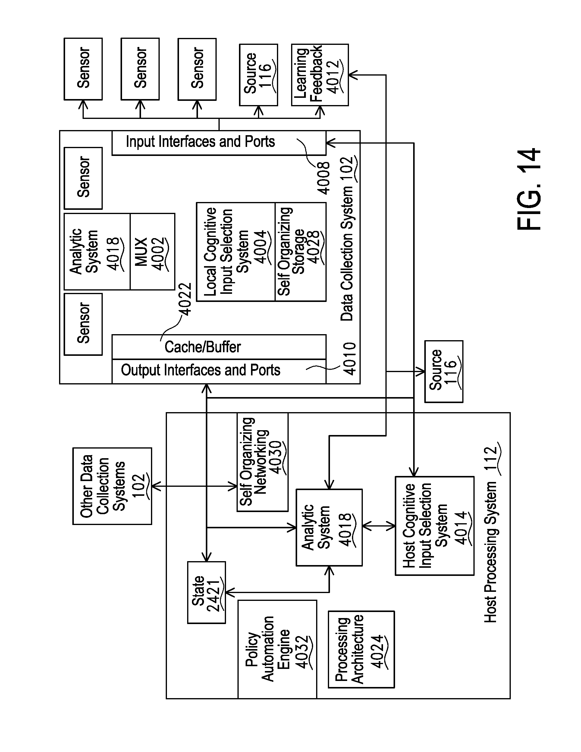
D00015

D00016

D00017

D00018

D00019

D00020

D00021

D00022

D00023

D00024

D00025

D00026

D00027

D00028

D00029

D00030

D00031

D00032

D00033

D00034

D00035

D00036

D00037

D00038

D00039

D00040

D00041

D00042

D00043
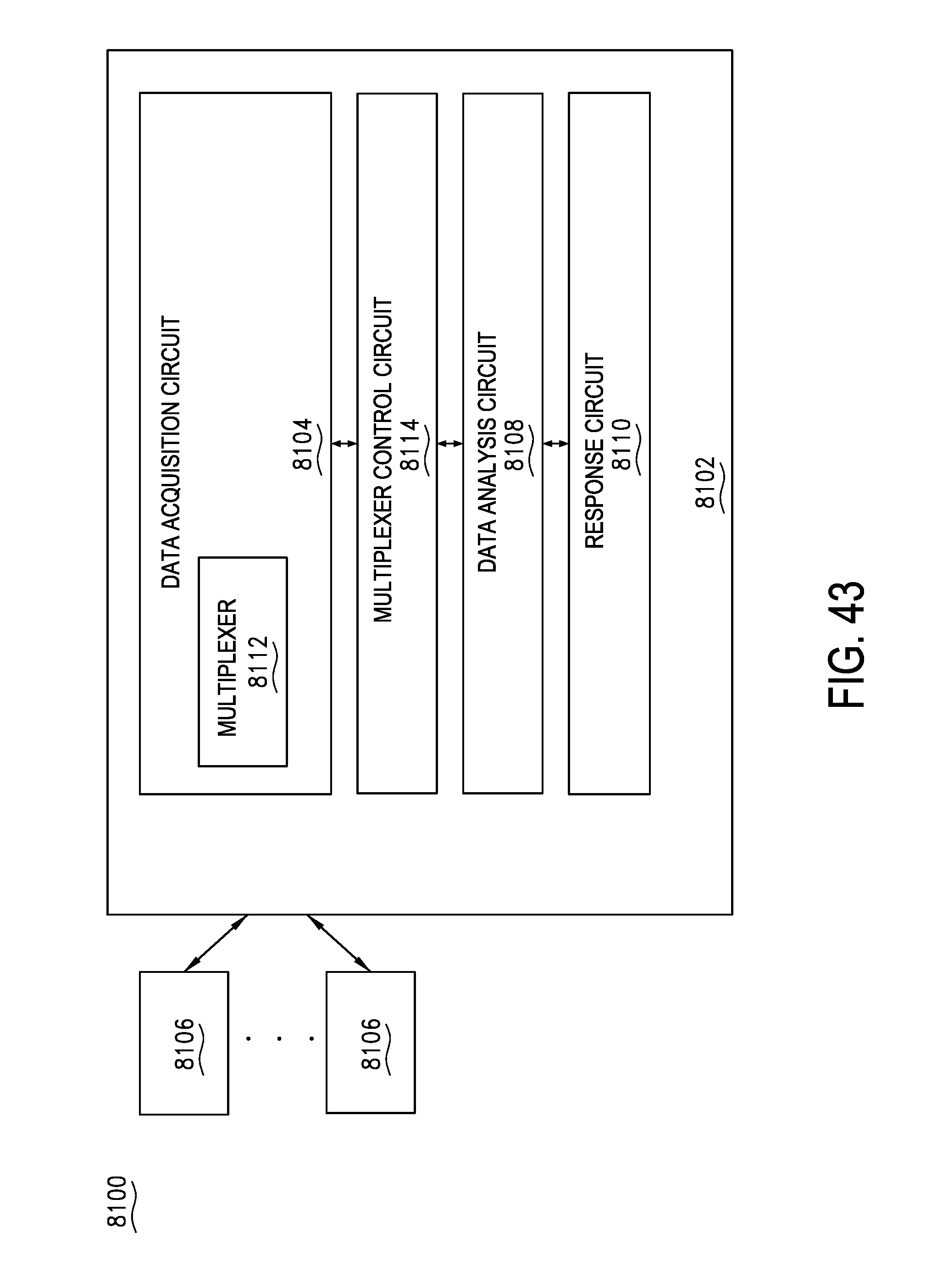
D00044

D00045

D00046

D00047

D00048

D00049

D00050

D00051

D00052

D00053

D00054

D00055

D00056

D00057

D00058

D00059

D00060

D00061

D00062

D00063

D00064

D00065

D00066

D00067

D00068

D00069

D00070

D00071

D00072

D00073

D00074

D00075

D00076
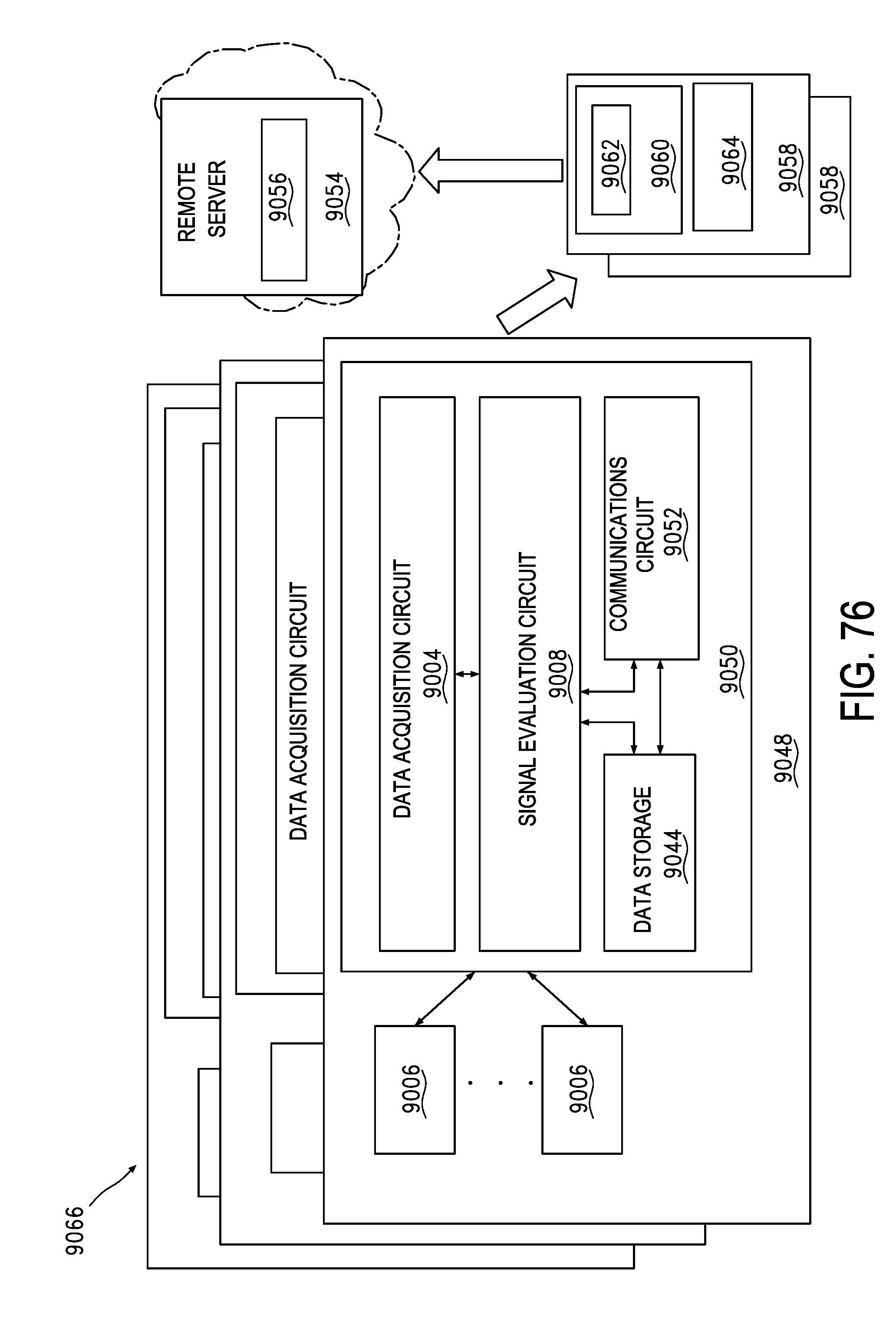
D00077

D00078

D00079

D00080

D00081

D00082

D00083

D00084

D00085

D00086

D00087

D00088

D00089

D00090

D00091

D00092

D00093

D00094

D00095

D00096

D00097

D00098

D00099

D00100

D00101

D00102

D00103

D00104

D00105

D00106

D00107

D00108

D00109

D00110

D00111

D00112

D00113

D00114
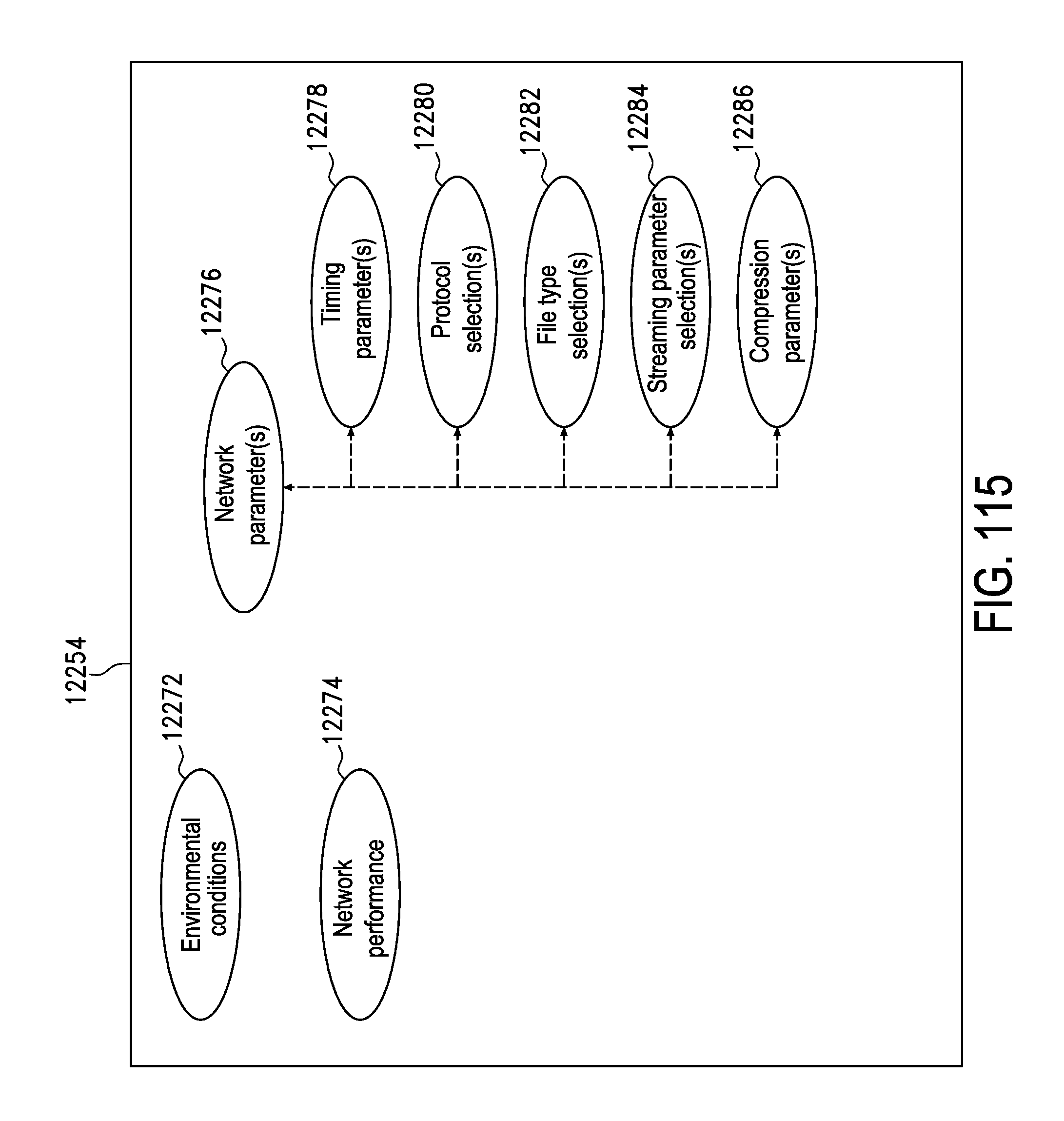
D00115

D00116

D00117

D00118

D00119

XML
uspto.report is an independent third-party trademark research tool that is not affiliated, endorsed, or sponsored by the United States Patent and Trademark Office (USPTO) or any other governmental organization. The information provided by uspto.report is based on publicly available data at the time of writing and is intended for informational purposes only.
While we strive to provide accurate and up-to-date information, we do not guarantee the accuracy, completeness, reliability, or suitability of the information displayed on this site. The use of this site is at your own risk. Any reliance you place on such information is therefore strictly at your own risk.
All official trademark data, including owner information, should be verified by visiting the official USPTO website at www.uspto.gov. This site is not intended to replace professional legal advice and should not be used as a substitute for consulting with a legal professional who is knowledgeable about trademark law.