Iterative Multi-level Equalization And Decoding
Kons; Shachar ; et al.
U.S. patent application number 16/273649 was filed with the patent office on 2019-06-06 for iterative multi-level equalization and decoding. The applicant listed for this patent is Cohere Technologies. Invention is credited to Ronny Hadani, Christian Ibars Casas, Shachar Kons.
| Application Number | 20190173617 16/273649 |
| Document ID | / |
| Family ID | 61163214 |
| Filed Date | 2019-06-06 |


View All Diagrams
| United States Patent Application | 20190173617 |
| Kind Code | A1 |
| Kons; Shachar ; et al. | June 6, 2019 |
ITERATIVE MULTI-LEVEL EQUALIZATION AND DECODING
Abstract
A wireless communication method for transmitting wireless signals from a transmitter includes receiving information bits for transmission, segmenting the information bits into a stream of segments, applying a corresponding forward error correction (FEC) code and an interleaver to each of the stream of segments and combining outputs of the interleaving to generate a stream of symbols, processing the stream of symbols to generate a waveform, and transmitting the waveform over a communication medium.
| Inventors: | Kons; Shachar; (Santa Clara, CA) ; Hadani; Ronny; (Santa Clara, CA) ; Ibars Casas; Christian; (Santa Clara, CA) | ||||||||||
| Applicant: |
|
||||||||||
|---|---|---|---|---|---|---|---|---|---|---|---|
| Family ID: | 61163214 | ||||||||||
| Appl. No.: | 16/273649 | ||||||||||
| Filed: | February 12, 2019 |
Related U.S. Patent Documents
| Application Number | Filing Date | Patent Number | ||
|---|---|---|---|---|
| PCT/US2017/046634 | Aug 11, 2017 | |||
| 16273649 | ||||
| 62374585 | Aug 12, 2016 | |||
| 62379184 | Aug 24, 2016 | |||
| Current U.S. Class: | 1/1 |
| Current CPC Class: | H04L 27/02 20130101; H04L 1/0071 20130101; H04L 1/0048 20130101; H04L 1/0041 20130101; H04L 27/2649 20130101; H04L 1/0045 20130101; H04L 5/0016 20130101; H04L 1/0001 20130101; H04L 25/03305 20130101; H04L 27/2647 20130101; H04L 5/0007 20130101; H04L 27/2639 20130101; H04L 1/0058 20130101; H04L 5/0023 20130101; H04L 1/0066 20130101; H04L 27/3488 20130101; H04B 1/00 20130101 |
| International Class: | H04L 1/00 20060101 H04L001/00; H04L 27/26 20060101 H04L027/26; H04L 5/00 20060101 H04L005/00; H04L 27/02 20060101 H04L027/02 |
Claims
1. A wireless communication method for transmitting orthogonal time frequency space (OTFS) modulated wireless signals from a transmitter, comprising: receiving information bits for transmission; segmenting the information bits into a stream of segments; applying a corresponding forward error correction (FEC) code to each of the stream of segments and combining outputs of the FECs to generate a stream of symbols; processing the stream of symbols to generate a waveform; and transmitting the waveform over a communication medium.
2. The method of claim 1, wherein each segment in the stream of segments has an equal bit length.
3. The method of claim 1, wherein the processing the stream of symbols includes: transforming the stream of symbols to orthogonal time frequency space (OTFS) domain by performing an OTFS transform on the stream of symbols.
4. The method of claim 1, wherein at least some of the FEC codes have different block sizes from each other.
5. The method of claim 1, wherein each stream of segments is applied to one or more of the constellation symbol label.
6. The method of claim 1, wherein the combining the outputs of the FECs includes: performing, on an output of each FEC, a corresponding interleaving operation; and combining outputs of the interleaving operations to generate the stream of symbols.
7. A wireless communication method, implemented at a receiver-side, for receiving a signal comprising multiple symbols; comprising: performing channel equalization on the signal to generate a channel equalized signal; logically dividing the channel equalized signal into a first number of segments, wherein the number of segment is equal to a second number of segments used at a transmitter-side to generate the signal; demodulating and symbol de-mapping the channel equalization signal in successive steps such that each step operates to recover one or more bits of one of the number of the segments to generate a demodulated bitstream; wherein an order in which the successive steps are performed depends on a reliability of success of recovering the one or more bits in each of the successive steps; processing the demodulated bitstream to generate information related to the bits from the signal; and providing a feedback signal to the channel equalization operation based on the processing of the demodulated bitstream.
8. The method of claim 7, wherein the processing the demodulated bitstream comprises forward error correction decoding using a plurality of forward error correction codes, at least some of which have different block sizes.
9. The method of claim 7, wherein the providing the feedback path comprises performing symbol mapping and orthogonal time frequency space transformation to generate a feedback signal.
10. The method of claim 7, wherein the order of which the successive steps are performed is from the most reliable bit to the least reliable bit.
11. The method of claim 7, wherein the processing the demodulated bitstream comprises deinterleaving each segment of the first number of segments, and forward error correction decoding using a plurality of forward error correction codes, at least some of which have different block sizes, outputs of the deinterleaving of the first number of segments.
12. The method of claim 7, wherein the providing the feedback signal comprises interleaving, the recovered one or more bit-related information from each of the first number of segments using a corresponding interleaver depth.
13. The method of claim 7, wherein the equalized signal is processed to an inverse orthogonal time frequency space transform prior to performing symbol demapping.
14. A wireless communication device comprising a processor configured to implement a method comprising: receiving information bits for transmission; segmenting the information bits into a stream of segments; applying a corresponding forward error correction (FEC) code to each of the stream of segments and combining outputs of the FECs to generate a stream of symbols; processing the stream of symbols to generate a waveform; and causing transmission of the waveform over a communication medium.
15. The wireless communication device of claim 14, wherein the processing the stream of symbols includes transforming the stream of symbols to orthogonal time frequency space (OTFS) domain by performing an OTFS transform on the stream of symbols.
16. The wireless communication device of claim 14, wherein the combining the outputs of the FEC includes: performing, on an output of each FEC, a corresponding interleaving operation; and combining outputs of the interleaving operations to generate the stream of symbols.
17. A wireless communication device comprising a processor configured to implement a method comprising: performing channel equalization on the signal to generate a channel equalized signal; logically dividing the channel equalized signal into a first number of segments, wherein the number of segment is equal to a second number of segments used at a transmitter-side to generate the signal; demodulating and symbol de-mapping the channel equalization signal in successive steps such that each step operates to recover one or more bits of one of the number of the segments to generate a demodulated bitstream; wherein an order in which the successive steps are performed depends on a reliability of success of recovering the one or more bits in each of the successive steps; processing the demodulated bitstream to generate information related to the bits from the signal; and providing a feedback signal to the channel equalization operation based on the processing of the demodulated bitstream.
18. The wireless communication device of claim 17, wherein the processing the demodulated bitstream comprises forward error correction decoding using a plurality of forward error correction codes, at least some of which have different block sizes.
19. The wireless communication device of claim 17, wherein the providing the feedback path comprises performing symbol mapping and orthogonal time frequency space transformation to generate a feedback signal.
20. The wireless communication device of claim 17, wherein the processing the demodulated bitstream comprises deinterleaving each segment of the first number of segments, and forward error correction decoding using a plurality of forward error correction codes, at least some of which have different block sizes, outputs of the deinterleaving of the first number of segments.
Description
PRIORITY CLAIM
[0001] This patent document is a continuation of PCT Application No. PCT/US2017/046631, filed Aug. 11, 2017, entitled "ITERATIVE MULTI-LEVEL EQUALIZATION AND DECODING" which claims the benefits and priority of U.S. Provisional Patent Application No. 62/374,585, filed Aug. 12, 2016, and to U.S. Provisional Patent Application No. 62/379,184, filed Aug. 24, 2016, both entitled "ITERATIVE MULTI-LEVEL EQUALIZATION AND DECODING." The entire contents of the before-mentioned patent applications are incorporated by reference as part of the disclosure of this application.
TECHNICAL FIELD
[0002] The present document relates to wireless communication, and more particularly, transmission and reception of multi-level constellation signals.
BACKGROUND
[0003] Due to an explosive growth in the number of wireless user devices and the amount of wireless data that these devices can generate or consume, current wireless communication networks are fast running out of bandwidth to accommodate such a high growth in data traffic and provide high quality of service to users.
[0004] Various efforts are underway in the telecommunication industry to come up with next generation of wireless technologies that can keep up with the demand on performance of wireless devices and networks.
SUMMARY
[0005] This document discloses techniques for transmission and reception of signals with improved error-rate performance, using multi-level constellations symbols.
[0006] In one example aspect, a method of wireless signal transmission is disclosed. The method includes receiving information bits for transmission, segmenting the information bits into a stream of segments, applying a corresponding forward error correction (FEC) code to each of the stream of segments, combining the streams to generate a stream of symbols, processing the stream of symbols to generate a waveform, and transmitting the waveform over a communication medium.
[0007] In another example aspect, a wireless communication method, implemented at a receiver-side is disclosed. The method include performing channel equalization on the signal to generate a channel equalized signal, logically dividing the channel equalized signal into a first number of segments, wherein the number of segment is equal to a second number of segments used at a transmitter-side to generate the signal, demodulating and symbol de-mapping the channel equalization signal in successive steps such that each step operates to recover one or more bits of one of the number of the segments to generate a demodulated bitstream, processing the demodulated bitstream to generate information related to the bits of the signal, and providing a feedback signal to the channel equalization operation based on the processing of the demodulated bitstream. The order in which the successive steps are performed depends on a reliability of success of recovering the one or more bits in each of the successive steps.
[0008] In another example aspect, a wireless communication apparatus that includes a processor is disclosed. The apparatus is configured to implement one of the methods described herein.
[0009] These, and other, features are described in this document.
DESCRIPTION OF THE DRAWINGS
[0010] Drawings described herein are used to provide a further understanding and constitute a part of this application. Example embodiments and illustrations thereof are used to explain the technology rather than limiting its scope.
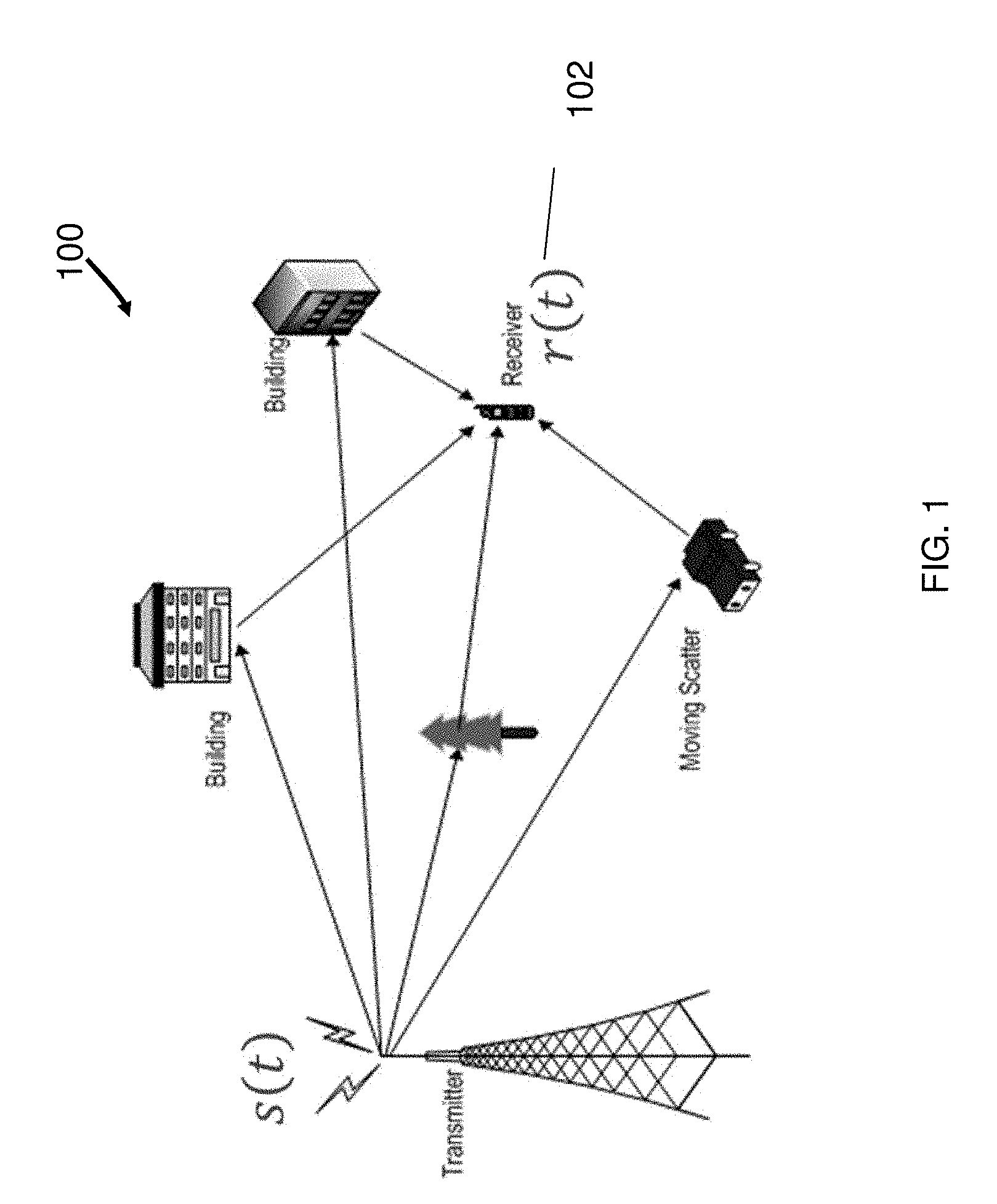
[0011] FIG. 1 shows an example communication network.
[0012] FIG. 2 is a block diagram showing an example of a transmission system.
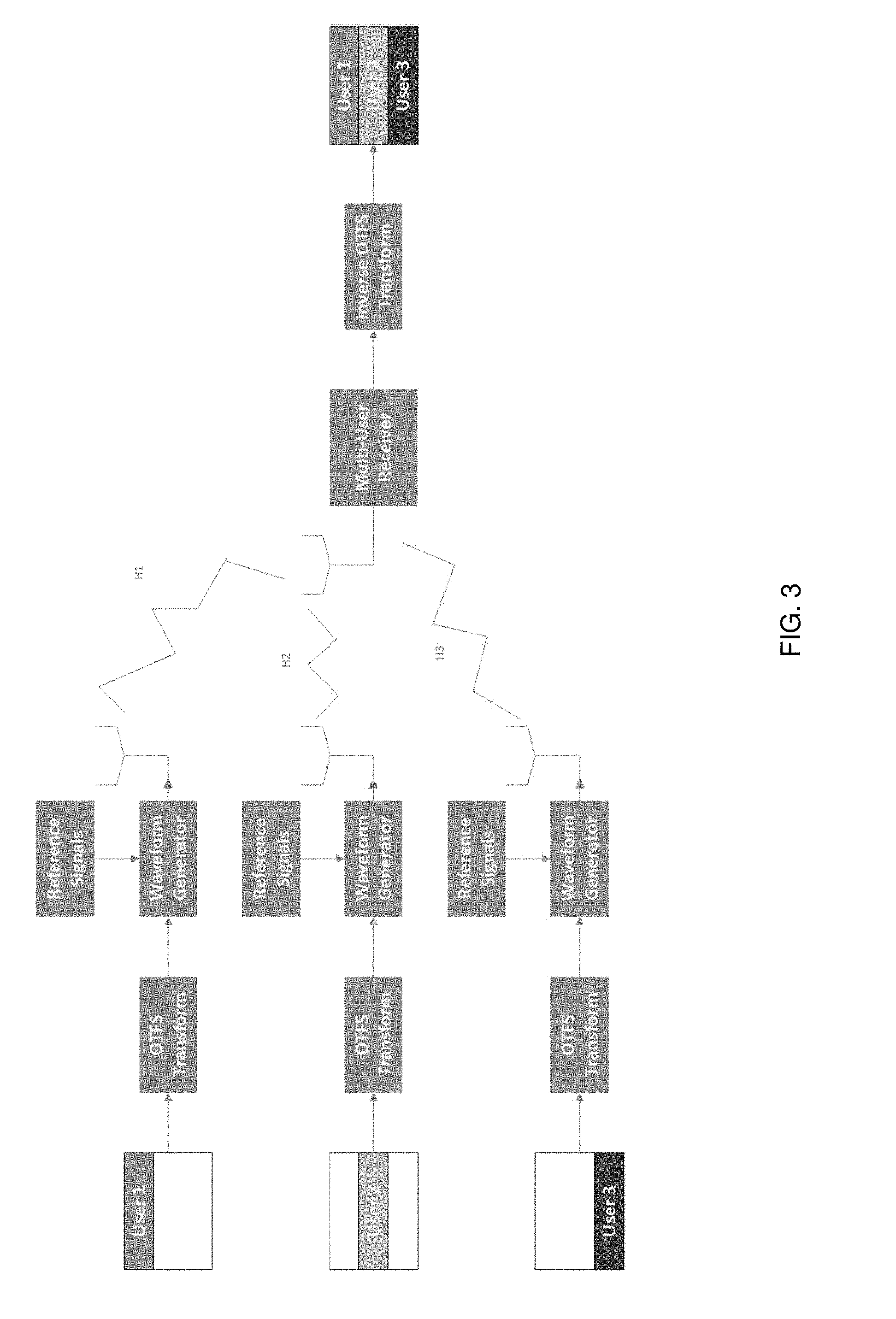
[0013] FIG. 3 is a block diagram showing an example of a multi-level transmission system.
[0014] FIG. 4 shows a block diagram of an example iterative receiver apparatus.
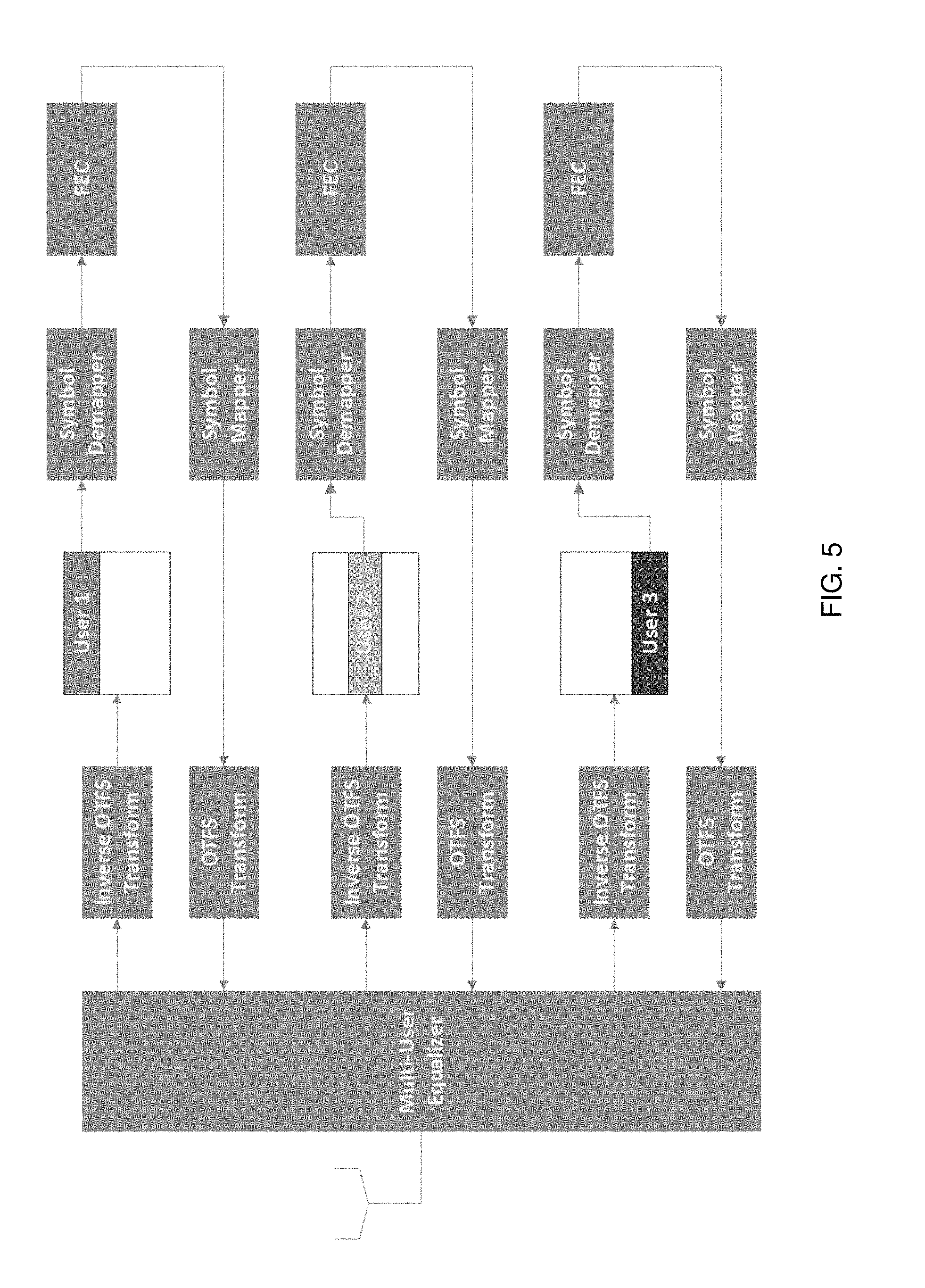
[0015] FIG. 5 shows a block diagram of an example iterative receiver apparatus that uses multi-level decoding.
[0016] FIG. 6 shows a flowchart of an example wireless communication transmission method.
[0017] FIG. 7 shows a flowchart of an example wireless communication reception method.
[0018] FIG. 8 shows an example of a wireless transceiver apparatus.
[0019] FIG. 9 is a block diagram showing an example of a multi-level transmission system that includes an interleaving function.
[0020] FIG. 10 is a block diagram showing of an example of an iterative receiver apparatus that includes a de-interleaving function.
DETAILED DESCRIPTION
[0021] To make the purposes, technical solutions and advantages of this disclosure more apparent, various embodiments are described in detail below with reference to the drawings. Unless otherwise noted, embodiments and features in embodiments of the present document may be combined with each other.
[0022] Section headings are used in the present document, including the appendices, to improve readability of the description and do not in any way limit the discussion to the respective sections only.
[0023] FIG. 1 shows an example communication network 100 in which the disclosed technologies can be implemented. The network 100 may include a base station transmitter that transmits wireless signals s(t) (downlink signals) to one or more receivers 102, the received signal being denoted as r(t), which may be located in a variety of locations, including inside or outside a building and in a moving vehicle. The receivers may transmit uplink transmissions to the base station, typically located near the wireless transmitter. The technology described herein may be implemented at a receiver 102, or by the receiving function of the base station.
[0024] A typical wireless signal transmission system usually may include a transmit chain 200, as shown in FIG. 2. Source data 202 is segmented into blocks (204), which are encoded by a Forward-Error-Correction (FEC) code of rate R into codewords (206). These codewords are segmented (208) into groups of q bits where each group is mapped to a constellation symbol (such as M-QAM, where 2q=M). These symbols may be transformed by an orthogonal time frequency space (OTFS) transform (210) and then used for the generation of the transmission waveform (212). In some embodiments, an orthogonal frequency division multiplexing (OFDM) technique may be used in 210. Alternatively, modulation based on other modulations schemes such as dispersed OTFS or a general M-dimensional transform may also be possible.
[0025] In transmit chain 200, all the source bits have (almost) equal protection by the FEC code, but the coded bits, which are mapped into different positions in the constellation symbol's label, do not typically have equal protection. Some of the bits in the constellation label may be more reliable than other bits (have lower probability of error). For example, in some standard constellation mappings, such as Gray mapping, the Most-Significant-Bits (MSBs) are typically more reliable than the Least-Significant-Bits (LSBs).
[0026] Described herein are alternative method for data segmentation and encoding along with its matching iterative receiver, which is advantageous in terms of error-rate performance.
[0027] Multi-Level Data Segmentation and Encoding
[0028] FIG. 3 depicts an example of a transmit chain 300 that uses multi-level data segmentation and encoding. In the scheme implemented by the transmit chain 300, shown in FIG. 3, the data is segmented into q multiple blocks of different sizes and encoded in q different levels by multiple FEC codes (306a to 306q) of different rates R.sub.1, R.sub.2, . . . , R.sub.q. In the simplest case, each FEC output is used to map a specific bit in each constellation symbol. For example, 8-QAM may be encoded with 3 levels using 3 different FEC codes. Their output maps the MSB, middle bit and LSB of the constellation symbol's label.
[0029] In various embodiments, the number of levels may be smaller than log.sub.2 M and each FEC may be connected to more than one bit in the constellation label. For example, in constellation mappings (308) where the real part of the complex constellation is independent of the imaginary part, pairs of constellation bits (one mapped to the real and one mapped to the imaginary) may be encoded together.
[0030] To achieve the best error-rate performance, the different FEC code rates may be optimally selected along with the choice of the constellation mapping.
[0031] Iterative Equalization & Decoding of Multi-Level Encoded Symbols
[0032] In general, iterative receivers exchange extrinsic information between the equalizer and the FEC decoder to achieve close to optimal performance, as shown in FIG. 4 for an OTFS receiver 400. The extrinsic information may include a priori knowledge of which transmission resources (e.g., time slots of subcarriers) use which particular FEC. For example, the equalizer 402 uses prior information on the data symbols coming from the FEC feedback path to improve the equalization of the symbols. This feedback path comprises a symbol mapper 410 and OTFS transformation module 412. Then, these symbols are converted to bit likelihoods that are FEC decoded. Several iterations are performed until all the source data is decoded correctly, or until some other stopping criteria is met. An inverse OTFS transform module 404 may apply inverse OTFS transform and a symbol demapper 406 may recover bits from modulation symbols.
[0033] Compared to other techniques described next, the error-rate performance of the scheme 400 may be degraded. One reason for the degradation may be because of the mixture of bits with different level of reliability in every FEC codeword that is being decoded. The constellation bits with low reliability make it harder for the FEC decoder to converge to the correct codeword and therefore, the feedback to the equalizer has less information to improve the equalization.
[0034] When multi-level encoding is applied at the transmitter (e.g., as shown in FIG. 3), the iterative receiver 550, in each decoding iteration, decodes only a part of the constellation bits. It typically starts with the most reliable bits and then proceeds in the next iterations to less reliable ones. This scheme, shown in FIG. 5, allows the equalizer to receive in earlier iterations priors, which are dominant from the constellation symbols point of view and better improve the equalization. When the FEC has successfully decoded one level, it switches to decode the next one. The receiver continues to iterate until all levels have been decoded successfully or until some other stopping criteria is met. The most reliable bits are often bits that are used to decide the "macro" region within the constellation map where a symbol lies--e.g., the quadrant in which a constellation symbol of a 4 or 8 QAM signal lies, followed by sub-quadrant within the quadrant, and so on. Thus, as shown in FIG. 5 the received signal may be equalized by the equalizer 402. In the forward path, the equalized signal may undergo an inverse OTFS transform (404), and the symbols from the resulting transformed signal may be demapped for decoding by multiple different FECs FEC.sub.1 to FECq (modules 558a to 558q). In the feedback path, the decoded symbol (bit) outputs of the FEC modules may be mapped to symbols (410) and transformed into OTFS domain signals (symbols) for feedback to the equalizer 402.
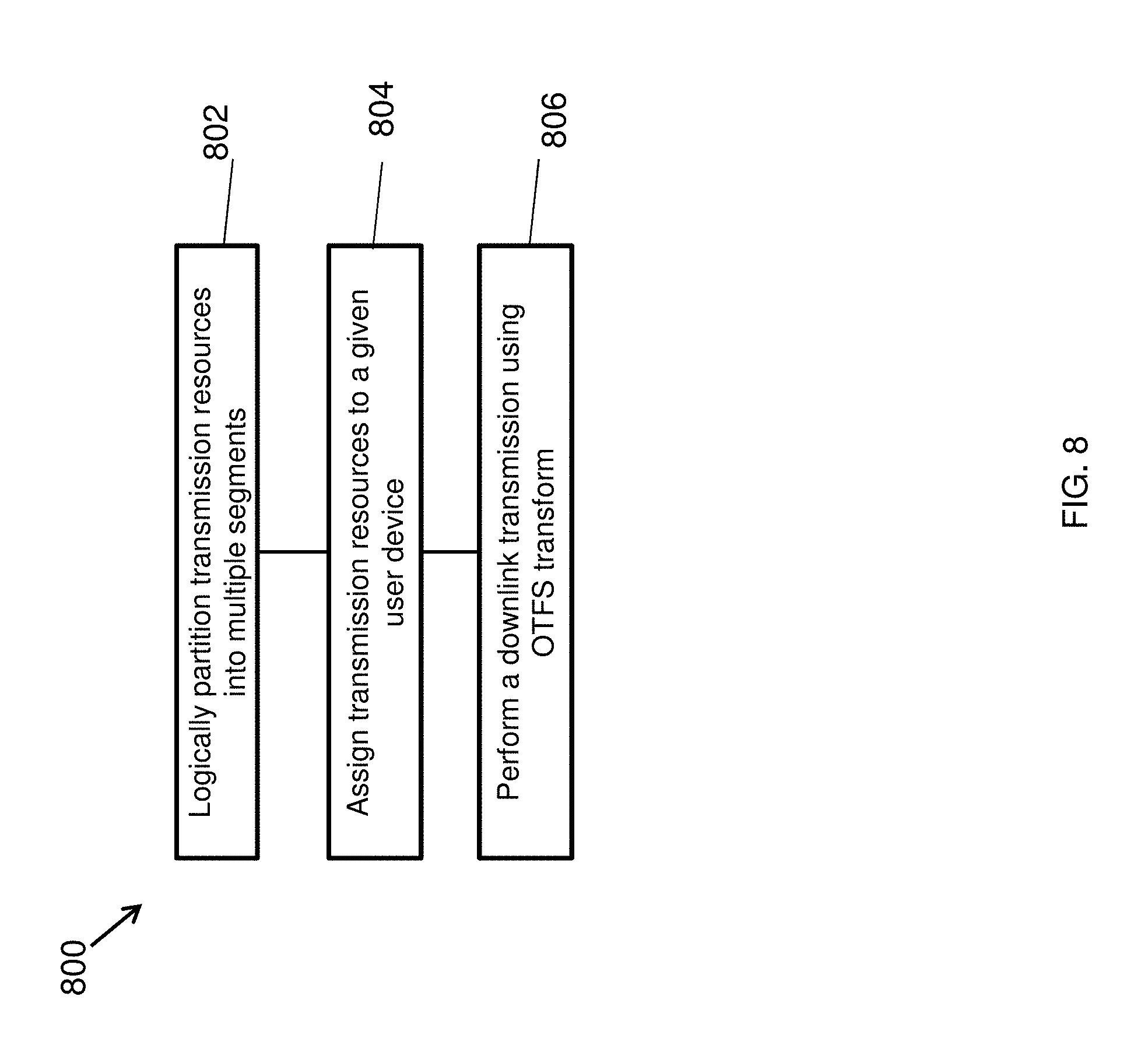
[0035] FIG. 6 shows a flowchart representation of an example method 600 of wireless signal transmission is disclosed. The method includes receiving information bits for transmission (602), segmenting the information bits into a stream of segments (604), applying a corresponding forward error correction (FEC) code to each of the stream of segments and combining outputs of the FECs to generate a stream of symbols (606), and generating an output signal for transmission (608). The output signal generation operation 608 may include processing the stream of symbols to generate a waveform, and transmitting the waveform over a communication medium. The processing of the stream of symbol may include operations such as digital to analog conversion, lowpass filtering,
[0036] In some embodiments, the segmentation operation may comprise serial-to-parallel conversion of the information bits such that each segment has a size equal to the number of bits used to generate constellations of a downstream modulation scheme. For example, 3 bits per segment may be used for 8 QAM modulation.
[0037] In some embodiments, the number of bits per segment may be equal to the block size for the downstream forward error correction scheme used. For example, 40 or 80 bit segments may be used for FEC block. In general, FECs with different error protection may be used and thus each FEC block may have a same number of bit size on the output (so that the outputs of each FEC can be combined to form symbols) but may have a different number of input bits. For example, the bit-expansion due to a stronger FEC code may mean fewer input bits will produce the same number of output FEC bits. However, in some embodiments, some FEC modules may have same input and output bit sizes but may offer different degrees of error correction coding due to algorithmic differences in the error correction code used for implementing the FEC.
[0038] In some embodiments, the transmission signal generation operation 606 may include application of a symplectic transform such as the OTFS transform to the signal to transform a corresponding delay-Doppler domain signal to a signal that is used for transmission.
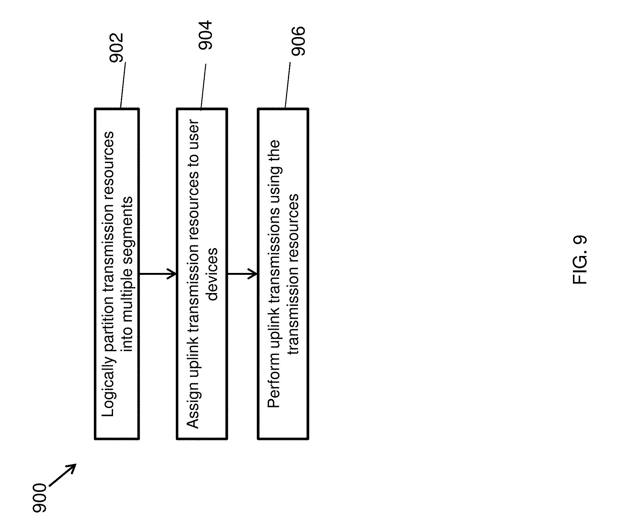
[0039] In another example aspect, a wireless communication method 700, implemented at a receiver-side is disclosed. The method 700 include performing channel equalization on the signal to generate a channel equalized signal (702), logically dividing the channel equalized signal into a first number of segments, wherein the number of segment is equal to a second number of segments used at a transmitter-side to generate the signal (704), demodulating and symbol de-mapping the channel equalization signal in successive steps such that each step operates to recover one or more bits of one of the number of the segments to generate a demodulated bitstream (706), processing the demodulated bitstream to generate information related to the bits from the signal (708), and providing a feedback signal to the channel equalization operation based on the processing of the demodulated bitstream (710). The order in which the successive steps are performed depends on a reliability of success of recovering the one bit in each of the successive steps.
[0040] For example, the processing 710 may include forward error correction decoding using a plurality of forward error correction codes, at least some of which have different block sizes. In some embodiments, the feedback provided in step 710 may be based on performing symbol mapping and orthogonal time frequency space transformation to generate a feedback signal. In some embodiments, the processing operation 710 may include deinterleaving each segment of the first number of segments, and forward error correction decoding using a plurality of forward error correction codes, at least some of which have different block sizes, outputs of the deinterleaving of the first number of segments.
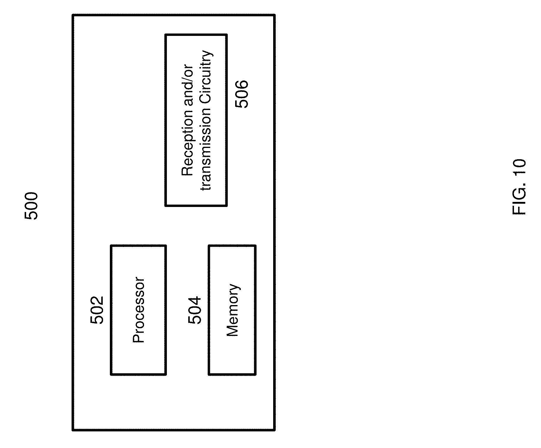
[0041] FIG. 8 shows an example of a wireless transceiver apparatus 500. The apparatus 500 may be used to implement method 600 or 700. The apparatus 500 includes a processor 502, a memory 504 that stores processor-executable instructions and data during computations performed by the processor. The apparatus 500 includes reception and/or transmission circuitry 506, e.g., including radio frequency operations for receiving or transmitting signals.
[0042] FIG. 9 depicts another example transmit chain 900 that uses multi-level data segmentation and encoding. Compared to the transmit chain 300, in the transmit chain 900, after data segmentation, each data segment may be encoded by its own FEC code (FEC.sub.1 to FEC.sub.q) and the corresponding interleaver functions 902a to 902q. The resulting outputs of the interleaver may then be combined prior to the symbol mapping 308. For example, data segments may represent bits with different importance or significance (e.g., least significant bit position, most significant bit position etc.). The corresponding FEC code may have a block size to provide an error protection that is proportional to the importance of that bit in the message being transmitted.
[0043] FIG. 10 depicts another example OTFS receiver 1000 in which, compared to the receiver 400, a deinterleaving function is used for each level. In the forward path of the receive chain, deinterleavers 1002a to 1002q are used, respectively, to deinterleave segments generated from the symbol demapper. The deinterleaved output of each deinterleaver is then fed into the corresponding FEC block. In the feedback path, the output of each FEC block is fed into the corresponding interleaver function 1004a to 1004q and the outputs of the interleaving operations are used by the symbol demapper 410.
[0044] Examples of Multi-Level Coding and Decoding Schemes
[0045] In some multi-level-coding schemes where different code rates are assigned to different bits in the constellation label, along with methods for obtaining the optimal rates. Decoder embodiments may start from the least reliable bits, decode them, remove them from the received signal and decode the next reliable bit up to the most reliable bit.
[0046] It will be appreciated that the disclosed techniques can be used to improve transmission/reception performance of wireless apparatus.
[0047] The disclosed and other embodiments, modules and the functional operations described in this document can be implemented in digital electronic circuitry, or in computer software, firmware, or hardware, including the structures disclosed in this document and their structural equivalents, or in combinations of one or more of them. The disclosed and other embodiments can be implemented as one or more computer program products, i.e., one or more modules of computer program instructions encoded on a computer readable medium for execution by, or to control the operation of, data processing apparatus. The computer readable medium can be a machine-readable storage device, a machine-readable storage substrate, a memory device, a composition of matter effecting a machine-readable propagated signal, or a combination of one or more them. The term "data processing apparatus" encompasses all apparatus, devices, and machines for processing data, including by way of example a programmable processor, a computer, or multiple processors or computers. The apparatus can include, in addition to hardware, code that creates an execution environment for the computer program in question, e.g., code that constitutes processor firmware, a protocol stack, a database management system, an operating system, or a combination of one or more of them. A propagated signal is an artificially generated signal, e.g., a machine-generated electrical, optical, or electromagnetic signal, that is generated to encode information for transmission to suitable receiver apparatus.
[0048] A computer program (also known as a program, software, software application, script, or code) can be written in any form of programming language, including compiled or interpreted languages, and it can be deployed in any form, including as a standalone program or as a module, component, subroutine, or other unit suitable for use in a computing environment. A computer program does not necessarily correspond to a file in a file system. A program can be stored in a portion of a file that holds other programs or data (e.g., one or more scripts stored in a markup language document), in a single file dedicated to the program in question, or in multiple coordinated files (e.g., files that store one or more modules, sub programs, or portions of code). A computer program can be deployed to be executed on one computer or on multiple computers that are located at one site or distributed across multiple sites and interconnected by a communication network.
[0049] The processes and logic flows described in this document can be performed by one or more programmable processors executing one or more computer programs to perform functions by operating on input data and generating output. The processes and logic flows can also be performed by, and apparatus can also be implemented as, special purpose logic circuitry, e.g., an FPGA (field programmable gate array) or an ASIC (application specific integrated circuit).
[0050] Processors suitable for the execution of a computer program include, by way of example, both general and special purpose microprocessors, and any one or more processors of any kind of digital computer. Generally, a processor will receive instructions and data from a read only memory or a random access memory or both. The essential elements of a computer are a processor for performing instructions and one or more memory devices for storing instructions and data. Generally, a computer will also include, or be operatively coupled to receive data from or transfer data to, or both, one or more mass storage devices for storing data, e.g., magnetic, magneto optical disks, or optical disks. However, a computer need not have such devices. Computer readable media suitable for storing computer program instructions and data include all forms of non-volatile memory, media and memory devices, including by way of example semiconductor memory devices, e.g., EPROM, EEPROM, and flash memory devices; magnetic disks, e.g., internal hard disks or removable disks; magneto optical disks; and CD ROM and DVD-ROM disks. The processor and the memory can be supplemented by, or incorporated in, special purpose logic circuitry.
[0051] While this patent document contains many specifics, these should not be construed as limitations on the scope of an invention that is claimed or of what may be claimed, but rather as descriptions of features specific to particular embodiments. Certain features that are described in this document in the context of separate embodiments can also be implemented in combination in a single embodiment. Conversely, various features that are described in the context of a single embodiment can also be implemented in multiple embodiments separately or in any suitable sub-combination. Moreover, although features may be described above as acting in certain combinations and even initially claimed as such, one or more features from a claimed combination can in some cases be excised from the combination, and the claimed combination may be directed to a sub-combination or a variation of a sub-combination. Similarly, while operations are depicted in the drawings in a particular order, this should not be understood as requiring that such operations be performed in the particular order shown or in sequential order, or that all illustrated operations be performed, to achieve desirable results.
[0052] Only a few examples and implementations are disclosed. Variations, modifications, and enhancements to the described examples and implementations and other implementations can be made based on what is disclosed.
* * * * *
D00000
D00001
D00002
D00003
D00004
D00005
D00006
D00007
D00008
D00009
D00010
D00011
D00012

D00013
XML
uspto.report is an independent third-party trademark research tool that is not affiliated, endorsed, or sponsored by the United States Patent and Trademark Office (USPTO) or any other governmental organization. The information provided by uspto.report is based on publicly available data at the time of writing and is intended for informational purposes only.
While we strive to provide accurate and up-to-date information, we do not guarantee the accuracy, completeness, reliability, or suitability of the information displayed on this site. The use of this site is at your own risk. Any reliance you place on such information is therefore strictly at your own risk.
All official trademark data, including owner information, should be verified by visiting the official USPTO website at www.uspto.gov. This site is not intended to replace professional legal advice and should not be used as a substitute for consulting with a legal professional who is knowledgeable about trademark law.