Adaptive Data Migration
Feigin; Boris ; et al.
U.S. patent application number 16/264459 was filed with the patent office on 2019-06-06 for adaptive data migration. The applicant listed for this patent is Pure Storage, Inc.. Invention is credited to Boris Feigin, Andrew Kleinerman, Svitlana Tumanova, Taher Vohra, Xiaohui Wang.
| Application Number | 20190171388 16/264459 |
| Document ID | / |
| Family ID | 61012027 |
| Filed Date | 2019-06-06 |


View All Diagrams
| United States Patent Application | 20190171388 |
| Kind Code | A1 |
| Feigin; Boris ; et al. | June 6, 2019 |
ADAPTIVE DATA MIGRATION
Abstract
A method for migration of data is provided. The method includes triggering a rebuild of data according to a first migration mechanism from a first storage drive to a second storage drive. Monitoring space utilization associated with the second storage drive, and adaptively switching the migration of the data from the first migration mechanism to a second migration mechanism based on the monitoring.
| Inventors: | Feigin; Boris; (San Francisco, CA) ; Kleinerman; Andrew; (Belmont, CA) ; Tumanova; Svitlana; (Mountain View, CA) ; Vohra; Taher; (Sunnyvale, CA) ; Wang; Xiaohui; (Mountain View, CA) | ||||||||||
| Applicant: |
|
||||||||||
|---|---|---|---|---|---|---|---|---|---|---|---|
| Family ID: | 61012027 | ||||||||||
| Appl. No.: | 16/264459 | ||||||||||
| Filed: | January 31, 2019 |
Related U.S. Patent Documents
| Application Number | Filing Date | Patent Number | ||
|---|---|---|---|---|
| 15339757 | Oct 31, 2016 | 10203903 | ||
| 16264459 | ||||
| 62367083 | Jul 26, 2016 | |||
| Current U.S. Class: | 1/1 |
| Current CPC Class: | G06F 3/061 20130101; G06F 2212/7205 20130101; G06F 12/0253 20130101; G06F 12/0246 20130101; G06F 3/0647 20130101; G06F 3/0653 20130101; G06F 3/0688 20130101; G06F 3/0607 20130101 |
| International Class: | G06F 3/06 20060101 G06F003/06; G06F 12/02 20060101 G06F012/02 |
Claims
1. A method of data migration within a storage system, performed by the storage system, comprising: switching, in an dynamic manner, between a first migration mechanism and a second migration mechanism, the first migration mechanism comprises: migrating first data with segments of the first data being unchanged during the data migration, and the second migration mechanism comprises; revising segments of second data during the data migration.
2. The method of claim 1, further comprising: determining an amount of storage memory space that is used or available in a plurality of portions of storage memory of a storage system, relative to a threshold value, the determining comprising; comparing a value associated with an imbalance of one or more of the portions of storage memory with the threshold value; adjusting relative utilization of the first migration mechanism and the second migration mechanism based on the comparing.
3. The method of claim 2, wherein each of the plurality of portions of storage memory comprises a write group.
4. The method of claim 2, wherein each of the plurality of portions of storage memory comprises a solid state drive (SSD).
5. The method of claim 1, wherein the revising includes deduplicating the segments of the second data.
6. The method of claim 1, wherein the first mechanism is a RAID (redundant array of independent disks) rebuild and the second mechanism is a garbage collection operation.
7. The method of claim 1, further comprising: determining an amount of compatible write groups and an amount of incompatible write groups, wherein the switching is based on the determining.
8. The method of claim 1, further comprising: adjusting a percentage of moves of the second migration based on a relative amount of fullness of compatible write groups with fullness of incompatible write groups.
9. A tangible, non-transitory, computer-readable media having instructions thereupon which, when executed by a processor, cause the processor to perform a method comprising: switching, in an dynamic manner, between a first migration mechanism and a second migration mechanism, the first migration mechanism comprises: migrating first data with segments of the first data being unchanged during the data migration, and the second migration mechanism comprises; revising segments of second data during the data migration.
10. The tangible, non-transitory, computer-readable media of claim 9, wherein the method further comprises: determining an amount of storage memory space that is used or available in a plurality of portions of storage memory of a storage system, relative to a threshold value, the determining comprising; comparing a value associated with an imbalance of one or more of the portions of storage memory with the threshold value; adjusting relative utilization of the first migration mechanism and the second migration mechanism based on the comparing.
11. The tangible, non-transitory, computer-readable media of claim 10, wherein each of the plurality of portions of storage memory comprises a write group.
12. The tangible, non-transitory, computer-readable media of claim 10, wherein each of the plurality of portions of storage memory comprises a solid state drive.
13. The tangible, non-transitory, computer-readable media of claim 9, wherein the revising includes deduplicating the segments of the second data.
14. The tangible, non-transitory, computer-readable media of claim 9, wherein the first mechanism is a RAID (redundant array of independent disks) rebuild and the second mechanism is a garbage collection operation
15. A storage system, comprising: storage memory; one or more processors; a space monitor, implemented in hardware, firmware or software executing on the one or more processors, the space monitor configurable to track storage memory space used for writing or available for writing in a plurality of portions of the storage memory; and a migration module, implemented in hardware, firmware or software executing on the one or more processors, the migration module configurable to perform a rebuild, an evacuation, or a targeted remap, using data migration switching between migrating live data and dead data and migrating only live data in a dynamic manner based on an amount of compatible write groups and an amount of incompatible write.
16. The storage system of claim 15, further comprising: the one or more processors including at least two processors arranged as a high-availability controller; and each of the plurality of portions of the storage memory including a write group that has a specified level of redundancy or error correction for data and acts as a failure domain.
17. The storage system of claim 15, further comprising: a plurality of blades each having a node and having solid-state memory as one of the plurality of portions of the storage memory, with multiple nodes coupled together as a storage cluster.
18. The storage system of claim 15, wherein: each of the plurality of portions of storage memory comprises a solid-state drive or solid-state storage, and wherein an amount of compatible write groups and an amount of incompatible write groups indicates an amount of imbalance across solid-state drives or solid-state storages.
19. The storage system of claim 15, wherein the migrating the live data and the dead data is a RAID (redundant array of independent disks) rebuild and the migrating the live data only is a garbage collection data move.
20. The storage system of claim 15, wherein the migration module adjusts a percentage of moves for migrating only live data based on a relative amount of fullness of compatible write groups with fullness of incompatible write groups.
Description
BACKGROUND
[0001] Solid-state memory, such as flash, is currently in use in solid-state drives (SSD) to augment or replace conventional hard disk drives (HDD), writable CD (compact disk) or writable DVD (digital versatile disk) drives, collectively known as spinning media, and tape drives, for storage of large amounts of data. Flash and other solid-state memories have characteristics that differ from spinning media. Yet, many solid-state drives are designed to conform to hard disk drive standards for compatibility reasons, which makes it difficult to provide enhanced features or take advantage of unique aspects of flash and other solid-state memory. Flash based arrays can be upgradeable. During these upgrades there may be a need to evacuate data from a shelf or migrate the data to a different shelf. It is within this context that the embodiments arise.
SUMMARY
[0002] In some embodiments, a method of data migration within a storage system is provided. The method includes determining an amount of storage memory space that is used or available in a plurality of portions of storage memory of a storage system, relative to a threshold value and selecting relative utilization of a first migration mechanism and a second migration mechanism, to perform within the storage memory, based on the determining. The method includes performing data migration within the storage memory, in accordance with the selecting.
[0003] In some embodiments, a tangible, non-transitory, computer-readable media is provided. The computer readable media has instructions thereupon which, when executed by a processor, cause the processor to perform a method. The method includes determining an amount of storage memory space that is used or available in a plurality of portions of storage memory of a storage system, relative to a threshold value. The method includes selecting relative utilization of a first migration mechanism and a second migration mechanism, to perform within the storage memory, based on the determining, and performing data migration within the storage memory, in accordance with the selecting
[0004] In some embodiments, a storage system is provided. The storage system includes storage memory and one or more processors. The system includes a space monitor, implemented in hardware, firmware or software executing on the one or more processors, the space monitor is configurable to track storage memory space used for writing or available for writing in a plurality of portions of the storage memory. The system includes a migration module, implemented in hardware, firmware or software executing on the one or more processors. The migration module is configurable to vary relative amounts or rates of a first migration mechanism and a second migration mechanism within the storage system, with varying the relative amounts or rates responsive to the space monitor tracking an amount of imbalance of the storage memory space used or available in the plurality of the portions of storage memory.
[0005] Other aspects and advantages of the embodiments will become apparent from the following detailed description taken in conjunction with the accompanying drawings which illustrate, by way of example, the principles of the described embodiments.
BRIEF DESCRIPTION OF THE DRAWINGS
[0006] The described embodiments and the advantages thereof may best be understood by reference to the following description taken in conjunction with the accompanying drawings. These drawings in no way limit any changes in form and detail that may be made to the described embodiments by one skilled in the art without departing from the spirit and scope of the described embodiments.
[0007] FIG. 1 is a perspective view of a storage cluster with multiple storage nodes and internal storage coupled to each storage node to provide network attached storage, in accordance with some embodiments.
[0008] FIG. 2 is a block diagram showing an interconnect switch coupling multiple storage nodes in accordance with some embodiments.
[0009] FIG. 3 is a multiple level block diagram, showing contents of a storage node and contents of one of the non-volatile solid state storage units in accordance with some embodiments.
[0010] FIG. 4 shows a storage server environment, which may utilize the embodiments of the storage nodes and storage units of FIGS. 1-3 in accordance with some embodiments.
[0011] FIG. 5 is a blade hardware block diagram, showing a control plane, compute and storage planes, and authorities interacting with underlying physical resources to perform distributed transactions, using embodiments of the storage nodes and storage units of FIGS. 1-3 in the storage server environment of FIG. 4 in accordance with some embodiments.
[0012] FIG. 6 is a block diagram of an embodiment of the space accounting logic shown in FIG. 3 in accordance with some embodiments.
[0013] FIG. 7 is an action diagram depicting migration from a storage unit, along with an incoming workload, directed by the space accounting logic and an allocator in a storage node in accordance with some embodiments.
[0014] FIG. 8 is a flow diagram of a method for evacuating or migrating data from a write group in accordance with some embodiments.
[0015] FIG. 9 is a block diagram of a high-availability controller storage system in accordance with some embodiments.
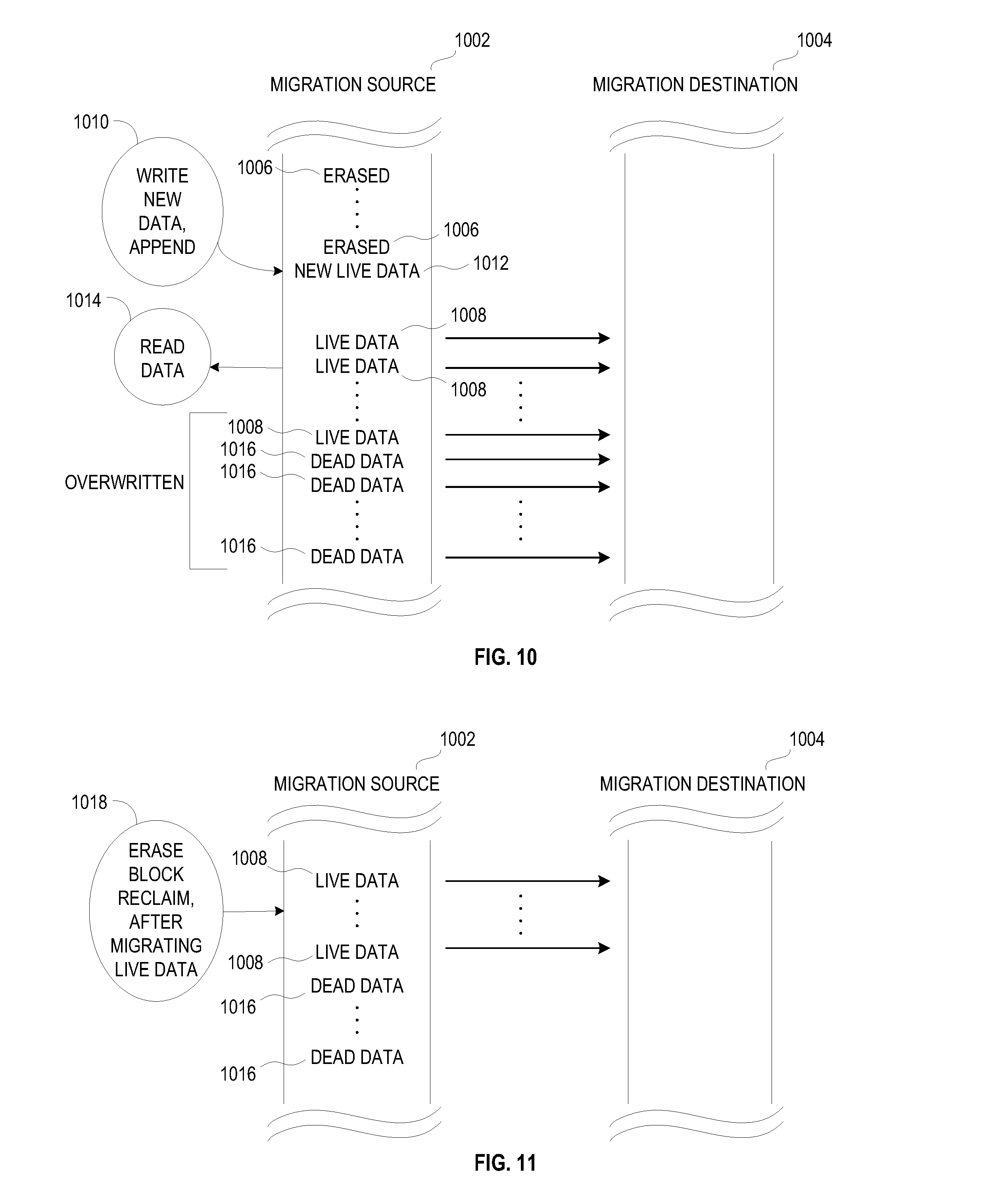
[0016] FIG. 10 depicts copying live and dead data in a migration in accordance with some embodiments.
[0017] FIG. 11 depicts copying only live data in a garbage collection data move in accordance with some embodiments.
[0018] FIG. 12 is a flow diagram of a method of data migration within a storage system in accordance with some embodiments.
[0019] FIG. 13 is an illustration showing an exemplary computing device which may implement the embodiments described herein.
DETAILED DESCRIPTION
[0020] Various storage systems described herein, and further storage systems, can be optimized for distribution of selected data, according to various criteria, in flash or other solid-state memory. The embodiments below provide for an upgradeable flash/solid state drive storage system. Upon an upgrade to the system, the data from a storage shelf may be required to be migrated to another shelf. The embodiments provide for a system and method that considers the space or storage capacity in the system and the ability to adaptively and/or dynamically adjust between differing migration techniques based on the monitoring of the space or storage capacity of the system. Principles of operation, variations, and implementation details for the adaptive migration of data for a rebuild operation or an upgrade of the system according to the available space in the system are provided below.
[0021] The embodiments below describe a storage cluster that stores user data, such as user data originating from one or more user or client systems or other sources external to the storage cluster. The storage cluster distributes user data across storage nodes housed within a chassis, using erasure coding and redundant copies of metadata. Erasure coding refers to a method of data protection or reconstruction in which data is stored across a set of different locations, such as disks, storage nodes or geographic locations. Flash memory is one type of solid-state memory that may be integrated with the embodiments, although the embodiments may be extended to other types of solid-state memory or other storage medium, including non-solid state memory. Control of storage locations and workloads are distributed across the storage locations in a clustered peer-to-peer system. Tasks such as mediating communications between the various storage nodes, detecting when a storage node has become unavailable, and balancing I/Os (inputs and outputs) across the various storage nodes, are all handled on a distributed basis. Data is laid out or distributed across multiple storage nodes in data fragments or stripes that support data recovery in some embodiments. Ownership of data can be reassigned within a cluster, independent of input and output patterns. This architecture described in more detail below allows a storage node in the cluster to fail, with the system remaining operational, since the data can be reconstructed from other storage nodes and thus remain available for input and output operations. In various embodiments, a storage node may be referred to as a cluster node, a blade, or a server.
[0022] The storage cluster is contained within a chassis, i.e., an enclosure housing one or more storage nodes. A mechanism to provide power to each storage node, such as a power distribution bus, and a communication mechanism, such as a communication bus that enables communication between the storage nodes are included within the chassis. The storage cluster can run as an independent system in one location according to some embodiments. In one embodiment, a chassis contains at least two instances of both the power distribution and the communication bus which may be enabled or disabled independently. The internal communication bus may be an Ethernet bus, however, other technologies such as Peripheral Component Interconnect (PCI) Express, InfiniBand, and others, are equally suitable. The chassis provides a port for an external communication bus for enabling communication between multiple chassis, directly or through a switch, and with client systems. The external communication may use a technology such as Ethernet, InfiniBand, Fibre Channel, etc. In some embodiments, the external communication bus uses different communication bus technologies for inter-chassis and client communication. If a switch is deployed within or between chassis, the switch may act as a translation between multiple protocols or technologies. When multiple chassis are connected to define a storage cluster, the storage cluster may be accessed by a client using either proprietary interfaces or standard interfaces such as network file system (NFS), common internet file system (CIFS), small computer system interface (SCSI) or hypertext transfer protocol (HTTP). Translation from the client protocol may occur at the switch, chassis external communication bus or within each storage node.
[0023] Each storage node may be one or more storage servers and each storage server is connected to one or more non-volatile solid state memory units, which may be referred to as storage units or storage devices. One embodiment includes a single storage server in each storage node and between one to eight non-volatile solid state memory units, however this one example is not meant to be limiting. The storage server may include a processor, dynamic random access memory (DRAM) and interfaces for the internal communication bus and power distribution for each of the power buses. Inside the storage node, the interfaces and storage unit share a communication bus, e.g., PCI Express, in some embodiments. The non-volatile solid state memory units may directly access the internal communication bus interface through a storage node communication bus, or request the storage node to access the bus interface. The non-volatile solid state memory unit contains an embedded central processing unit (CPU), solid state storage controller, and a quantity of solid state mass storage, e.g., between 2-32 terabytes (TB) in some embodiments. An embedded volatile storage medium, such as DRAM, and an energy reserve apparatus are included in the non-volatile solid state memory unit. In some embodiments, the energy reserve apparatus is a capacitor, super-capacitor, or battery that enables transferring a subset of DRAM contents to a stable storage medium in the case of power loss. In some embodiments, the non-volatile solid state memory unit is constructed with a storage class memory, such as phase change or magnetoresistive random access memory (MRAIVI) that substitutes for DRAM and enables a reduced power hold-up apparatus.
[0024] One of many features of the storage nodes and non-volatile solid state storage is the ability to proactively rebuild data in a storage cluster. The storage nodes and non-volatile solid state storage can determine when a storage node or non-volatile solid state storage in the storage cluster is unreachable, independent of whether there is an attempt to read data involving that storage node or non-volatile solid state storage. The storage nodes and non-volatile solid state storage then cooperate to recover and rebuild the data in at least partially new locations. This constitutes a proactive rebuild, in that the system rebuilds data without waiting until the data is needed for a read access initiated from a client system employing the storage cluster. These and further details of the storage memory and operation thereof are discussed below.
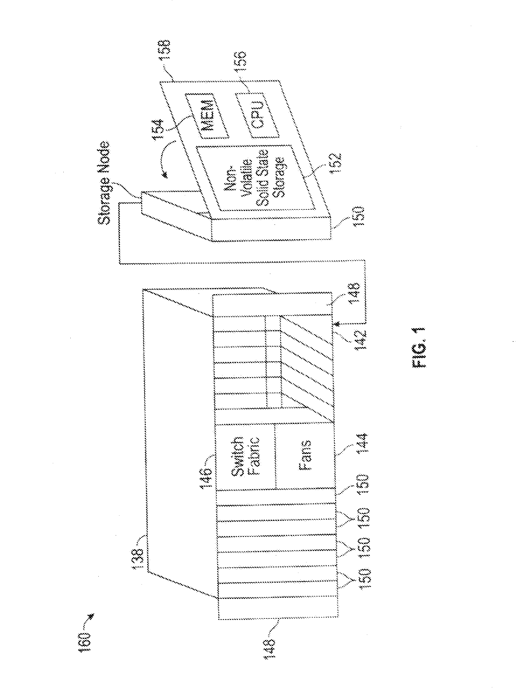
[0025] FIG. 1 is a perspective view of a storage cluster 160, with multiple storage nodes 150 and internal solid-state memory coupled to each storage node to provide network attached storage or storage area network, in accordance with some embodiments. A network attached storage, storage area network, or a storage cluster, or other storage memory, could include one or more storage clusters 160, each having one or more storage nodes 150, in a flexible and reconfigurable arrangement of both the physical components and the amount of storage memory provided thereby. The storage cluster 160 is designed to fit in a rack, and one or more racks can be set up and populated as desired for the storage memory. The storage cluster 160 has a chassis 138 having multiple slots 142. It should be appreciated that chassis 138 may be referred to as a housing, enclosure, or rack unit. In one embodiment, the chassis 138 has fourteen slots 142, although other numbers of slots are readily devised. For example, some embodiments have four slots, eight slots, sixteen slots, thirty-two slots, or other suitable number of slots. Each slot 142 can accommodate one storage node 150 in some embodiments. Chassis 138 includes flaps 148 that can be utilized to mount the chassis 138 on a rack. Fans 144 provide air circulation for cooling of the storage nodes 150 and components thereof, although other cooling components could be used, or an embodiment could be devised without cooling components. A switch fabric 146 couples storage nodes 150 within chassis 138 together and to a network for communication to the memory. In an embodiment depicted in FIG. 1, the slots 142 to the left of the switch fabric 146 and fans 144 are shown occupied by storage nodes 150, while the slots 142 to the right of the switch fabric 146 and fans 144 are empty and available for insertion of storage node 150 for illustrative purposes. This configuration is one example, and one or more storage nodes 150 could occupy the slots 142 in various further arrangements. The storage node arrangements need not be sequential or adjacent in some embodiments. Storage nodes 150 are hot pluggable, meaning that a storage node 150 can be inserted into a slot 142 in the chassis 138, or removed from a slot 142, without stopping or powering down the system. Upon insertion or removal of storage node 150 from slot 142, the system automatically reconfigures in order to recognize and adapt to the change. Reconfiguration, in some embodiments, includes restoring redundancy and/or rebalancing data or load.
[0026] Each storage node 150 can have multiple components. In the embodiment shown here, the storage node 150 includes a printed circuit board 158 populated by a CPU 156, i.e., processor, a memory 154 coupled to the CPU 156, and a non-volatile solid state storage 152 coupled to the CPU 156, although other mountings and/or components could be used in further embodiments. The memory 154 has instructions which are executed by the CPU 156 and/or data operated on by the CPU 156. As further explained below, the non-volatile solid state storage 152 includes flash or, in further embodiments, other types of solid-state memory.
[0027] Referring to FIG. 1, storage cluster 160 is scalable, meaning that storage capacity with non-uniform storage sizes is readily added, as described above. One or more storage nodes 150 can be plugged into or removed from each chassis and the storage cluster self-configures in some embodiments. Plug-in storage nodes 150, whether installed in a chassis as delivered or later added, can have different sizes. For example, in one embodiment a storage node 150 can have any multiple of 4 TB, e.g., 8 TB, 12 TB, 16 TB, 32 TB, etc. In further embodiments, a storage node 150 could have any multiple of other storage amounts or capacities. Storage capacity of each storage node 150 is broadcast, and influences decisions of how to stripe the data. For maximum storage efficiency, an embodiment can self-configure as wide as possible in the stripe, subject to a predetermined requirement of continued operation with loss of up to one, or up to two, non-volatile solid state storage units 152 or storage nodes 150 within the chassis.
[0028] FIG. 2 is a block diagram showing a communications interconnect 170 and power distribution bus 172 coupling multiple storage nodes 150. Referring back to FIG. 1, the communications interconnect 170 can be included in or implemented with the switch fabric 146 in some embodiments. Where multiple storage clusters 160 occupy a rack, the communications interconnect 170 can be included in or implemented with a top of rack switch, in some embodiments. As illustrated in FIG. 2, storage cluster 160 is enclosed within a single chassis 138. External port 176 is coupled to storage nodes 150 through communications interconnect 170, while external port 174 is coupled directly to a storage node. External power port 178 is coupled to power distribution bus 172. Storage nodes 150 may include varying amounts and differing capacities of non-volatile solid state storage 152 as described with reference to FIG. 1. In addition, one or more storage nodes 150 may be a compute only storage node as illustrated in FIG. 2. Authorities 168 are implemented on the non-volatile solid state storages 152, for example as lists or other data structures stored in memory. In some embodiments the authorities are stored within the non-volatile solid state storage 152 and supported by software executing on a controller or other processor of the non-volatile solid state storage 152. In a further embodiment, authorities 168 are implemented on the storage nodes 150, for example as lists or other data structures stored in the memory 154 and supported by software executing on the CPU 156 of the storage node 150. Authorities 168 control how and where data is stored in the non-volatile solid state storages 152 in some embodiments. This control assists in determining which type of erasure coding scheme is applied to the data, and which storage nodes 150 have which portions of the data. Each authority 168 may be assigned to a non-volatile solid state storage 152. Each authority may control a range of inode numbers, segment numbers, or other data identifiers which are assigned to data by a file system, by the storage nodes 150, or by the non-volatile solid state storage 152, in various embodiments.
[0029] Every piece of data, and every piece of metadata, has redundancy in the system in some embodiments. In addition, every piece of data and every piece of metadata has an owner, which may be referred to as an authority. If that authority is unreachable, for example through failure of a storage node, there is a plan of succession for how to find that data or that metadata. In various embodiments, there are redundant copies of authorities 168. Authorities 168 have a relationship to storage nodes 150 and non-volatile solid state storage 152 in some embodiments. Each authority 168, covering a range of data segment numbers or other identifiers of the data, may be assigned to a specific non-volatile solid state storage 152. In some embodiments the authorities 168 for all of such ranges are distributed over the non-volatile solid state storages 152 of a storage cluster. Each storage node 150 has a network port that provides access to the non-volatile solid state storage(s) 152 of that storage node 150. Data can be stored in a segment, which is associated with a segment number and that segment number is an indirection for a configuration of a RAID (redundant array of independent disks) stripe in some embodiments. The assignment and use of the authorities 168 thus establishes an indirection to data. Indirection may be referred to as the ability to reference data indirectly, in this case via an authority 168, in accordance with some embodiments. A segment identifies a set of non-volatile solid state storage 152 and a local identifier into the set of non-volatile solid state storage 152 that may contain data. In some embodiments, the local identifier is an offset into the device and may be reused sequentially by multiple segments. In other embodiments the local identifier is unique for a specific segment and never reused. The offsets in the non-volatile solid state storage 152 are applied to locating data for writing to or reading from the non-volatile solid state storage 152 (in the form of a RAID stripe). Data is striped across multiple units of non-volatile solid state storage 152, which may include or be different from the non-volatile solid state storage 152 having the authority 168 for a particular data segment.
[0030] If there is a change in where a particular segment of data is located, e.g., during a data move or a data reconstruction, the authority 168 for that data segment should be consulted, at that non-volatile solid state storage 152 or storage node 150 having that authority 168. In order to locate a particular piece of data, embodiments calculate a hash value for a data segment or apply an inode number or a data segment number. The output of this operation points to a non-volatile solid state storage 152 having the authority 168 for that particular piece of data. In some embodiments there are two stages to this operation. The first stage maps an entity identifier (ID), e.g., a segment number, inode number, or directory number to an authority identifier. This mapping may include a calculation such as a hash or a bit mask. The second stage is mapping the authority identifier to a particular non-volatile solid state storage 152, which may be done through an explicit mapping. The operation is repeatable, so that when the calculation is performed, the result of the calculation repeatably and reliably points to a particular non-volatile solid state storage 152 having that authority 168. The operation may include the set of reachable storage nodes as input. If the set of reachable non-volatile solid state storage units changes the optimal set changes. In some embodiments, the persisted value is the current assignment (which is always true) and the calculated value is the target assignment the cluster will attempt to reconfigure towards. This calculation may be used to determine the optimal non-volatile solid state storage 152 for an authority in the presence of a set of non-volatile solid state storage 152 that are reachable and constitute the same cluster. The calculation also determines an ordered set of peer non-volatile solid state storage 152 that will also record the authority to non-volatile solid state storage mapping so that the authority may be determined even if the assigned non-volatile solid state storage is unreachable. A duplicate or substitute authority 168 may be consulted if a specific authority 168 is unavailable in some embodiments.
[0031] With reference to FIGS. 1 and 2, two of the many tasks of the CPU 156 on a storage node 150 are to break up write data, and reassemble read data. When the system has determined that data is to be written, the authority 168 for that data is located as above. When the segment ID for data is already determined the request to write is forwarded to the non-volatile solid state storage 152 currently determined to be the host of the authority 168 determined from the segment. The host CPU 156 of the storage node 150, on which the non-volatile solid state storage 152 and corresponding authority 168 reside, then breaks up or shards the data and transmits the data out to various non-volatile solid state storage 152. The transmitted data is written as a data stripe in accordance with an erasure coding scheme. In some embodiments, data is requested to be pulled, and in other embodiments, data is pushed. In reverse, when data is read, the authority 168 for the segment ID containing the data is located as described above. The host CPU 156 of the storage node 150 on which the non-volatile solid state storage 152 and corresponding authority 168 reside requests the data from the non-volatile solid state storage and corresponding storage nodes pointed to by the authority. In some embodiments the data is read from flash storage as a data stripe. The host CPU 156 of storage node 150 then reassembles the read data, correcting any errors (if present) according to the appropriate erasure coding scheme, and forwards the reassembled data to the network. In further embodiments, some or all of these tasks can be handled in the non-volatile solid state storage 152. In some embodiments, the segment host requests the data be sent to storage node 150 by requesting pages from storage and then sending the data to the storage node making the original request.
[0032] In some systems, for example in UNIX-style file systems, data is handled with an index node or inode, which specifies a data structure that represents an object in a file system. The object could be a file or a directory, for example. Metadata may accompany the object, as attributes such as permission data and a creation timestamp, among other attributes. A segment number could be assigned to all or a portion of such an object in a file system. In other systems, data segments are handled with a segment number assigned elsewhere. For purposes of discussion, the unit of distribution is an entity, and an entity can be a file, a directory or a segment. That is, entities are units of data or metadata stored by a storage system. Entities are grouped into sets called authorities. Each authority has an authority owner, which is a storage node that has the exclusive right to update the entities in the authority. In other words, a storage node contains the authority, and that the authority, in turn, contains entities.
[0033] A segment is a logical container of data in accordance with some embodiments. A segment is an address space between medium address space and physical flash locations, i.e., the data segment number, are in this address space. Segments may also contain meta-data, which enable data redundancy to be restored (rewritten to different flash locations or devices) without the involvement of higher level software. In one embodiment, an internal format of a segment contains client data and medium mappings to determine the position of that data. Each data segment is protected, e.g., from memory and other failures, by breaking the segment into a number of data and parity shards, where applicable. The data and parity shards are distributed, i.e., striped, across non-volatile solid state storage 152 coupled to the host CPUs 156 (See FIG. 5) in accordance with an erasure coding scheme. Usage of the term segments refers to the container and its place in the address space of segments in some embodiments. Usage of the term stripe refers to the same set of shards as a segment and includes how the shards are distributed along with redundancy or parity information in accordance with some embodiments.
[0034] A series of address-space transformations takes place across an entire storage system. At the top are the directory entries (file names) which link to an inode. Inodes point into medium address space, where data is logically stored. Medium addresses may be mapped through a series of indirect mediums to spread the load of large files, or implement data services like deduplication or snapshots. Medium addresses may be mapped through a series of indirect mediums to spread the load of large files, or implement data services like deduplication or snapshots. Segment addresses are then translated into physical flash locations. Physical flash locations have an address range bounded by the amount of flash in the system in accordance with some embodiments. Medium addresses and segment addresses are logical containers, and in some embodiments use a 128 bit or larger identifier so as to be practically infinite, with a likelihood of reuse calculated as longer than the expected life of the system. Addresses from logical containers are allocated in a hierarchical fashion in some embodiments. Initially, each non-volatile solid state storage unit 152 may be assigned a range of address space. Within this assigned range, the non-volatile solid state storage 152 is able to allocate addresses without synchronization with other non-volatile solid state storage 152.
[0035] Data and metadata is stored by a set of underlying storage layouts that are optimized for varying workload patterns and storage devices. These layouts incorporate multiple redundancy schemes, compression formats and index algorithms. Some of these layouts store information about authorities and authority masters, while others store file metadata and file data. The redundancy schemes include error correction codes that tolerate corrupted bits within a single storage device (such as a NAND flash chip), erasure codes that tolerate the failure of multiple storage nodes, and replication schemes that tolerate data center or regional failures. In some embodiments, low density parity check (LDPC) code is used within a single storage unit. Reed-Solomon encoding is used within a storage cluster, and mirroring is used within a storage grid in some embodiments. Metadata may be stored using an ordered log structured index (such as a Log Structured Merge Tree), and large data may not be stored in a log structured layout.
[0036] In order to maintain consistency across multiple copies of an entity, the storage nodes agree implicitly on two things through calculations: (1) the authority that contains the entity, and (2) the storage node that contains the authority. The assignment of entities to authorities can be done by pseudo randomly assigning entities to authorities, by splitting entities into ranges based upon an externally produced key, or by placing a single entity into each authority. Examples of pseudorandom schemes are linear hashing and the Replication Under Scalable Hashing (RUSH) family of hashes, including Controlled Replication Under Scalable Hashing (CRUSH). In some embodiments, pseudo-random assignment is utilized only for assigning authorities to nodes because the set of nodes can change. The set of authorities cannot change so any subjective function may be applied in these embodiments. Some placement schemes automatically place authorities on storage nodes, while other placement schemes rely on an explicit mapping of authorities to storage nodes. In some embodiments, a pseudorandom scheme is utilized to map from each authority to a set of candidate authority owners. A pseudorandom data distribution function related to CRUSH may assign authorities to storage nodes and create a list of where the authorities are assigned. Each storage node has a copy of the pseudorandom data distribution function, and can arrive at the same calculation for distributing, and later finding or locating an authority. Each of the pseudorandom schemes requires the reachable set of storage nodes as input in some embodiments in order to conclude the same target nodes. Once an entity has been placed in an authority, the entity may be stored on physical devices so that no expected failure will lead to unexpected data loss. In some embodiments, rebalancing algorithms attempt to store the copies of all entities within an authority in the same layout and on the same set of machines.
[0037] Examples of expected failures include device failures, stolen machines, datacenter fires, and regional disasters, such as nuclear or geological events. Different failures lead to different levels of acceptable data loss. In some embodiments, a stolen storage node impacts neither the security nor the reliability of the system, while depending on system configuration, a regional event could lead to no loss of data, a few seconds or minutes of lost updates, or even complete data loss.
[0038] In the embodiments, the placement of data for storage redundancy is independent of the placement of authorities for data consistency. In some embodiments, storage nodes that contain authorities do not contain any persistent storage. Instead, the storage nodes are connected to non-volatile solid state storage units that do not contain authorities. The communications interconnect between storage nodes and non-volatile solid state storage units consists of multiple communication technologies and has non-uniform performance and fault tolerance characteristics. In some embodiments, as mentioned above, non-volatile solid state storage units are connected to storage nodes via PCI express, storage nodes are connected together within a single chassis using Ethernet backplane, and chassis are connected together to form a storage cluster. Storage clusters are connected to clients using Ethernet or fiber channel in some embodiments. If multiple storage clusters are configured into a storage grid, the multiple storage clusters are connected using the Internet or other long-distance networking links, such as a "metro scale" link or private link that does not traverse the internet.
[0039] Authority owners have the exclusive right to modify entities, to migrate entities from one non-volatile solid state storage unit to another non-volatile solid state storage unit, and to add and remove copies of entities. This allows for maintaining the redundancy of the underlying data. When an authority owner fails, is going to be decommissioned, or is overloaded, the authority is transferred to a new storage node. Transient failures make it non-trivial to ensure that all non-faulty machines agree upon the new authority location. The ambiguity that arises due to transient failures can be achieved automatically by a consensus protocol such as Paxos, hot-warm failover schemes, via manual intervention by a remote system administrator, or by a local hardware administrator (such as by physically removing the failed machine from the cluster, or pressing a button on the failed machine). In some embodiments, a consensus protocol is used, and failover is automatic. If too many failures or replication events occur in too short a time period, the system goes into a self-preservation mode and halts replication and data movement activities until an administrator intervenes in accordance with some embodiments.
[0040] As authorities are transferred between storage nodes and authority owners update entities in their authorities, the system transfers messages between the storage nodes and non-volatile solid state storage units. With regard to persistent messages, messages that have different purposes are of different types. Depending on the type of the message, the system maintains different ordering and durability guarantees. As the persistent messages are being processed, the messages are temporarily stored in multiple durable and non-durable storage hardware technologies. In some embodiments, messages are stored in RAM, NVRAM and on NAND flash devices, and a variety of protocols are used in order to make efficient use of each storage medium. Latency-sensitive client requests may be persisted in replicated NVRAM, and then later NAND, while background rebalancing operations are persisted directly to NAND.
[0041] Persistent messages are persistently stored prior to being transmitted. This allows the system to continue to serve client requests despite failures and component replacement. Although many hardware components contain unique identifiers that are visible to system administrators, manufacturer, hardware supply chain and ongoing monitoring quality control infrastructure, applications running on top of the infrastructure address virtualize addresses. These virtualized addresses do not change over the lifetime of the storage system, regardless of component failures and replacements. This allows each component of the storage system to be replaced over time without reconfiguration or disruptions of client request processing.
[0042] In some embodiments, the virtualized addresses are stored with sufficient redundancy. A continuous monitoring system correlates hardware and software status and the hardware identifiers. This allows detection and prediction of failures due to faulty components and manufacturing details. The monitoring system also enables the proactive transfer of authorities and entities away from impacted devices before failure occurs by removing the component from the critical path in some embodiments.
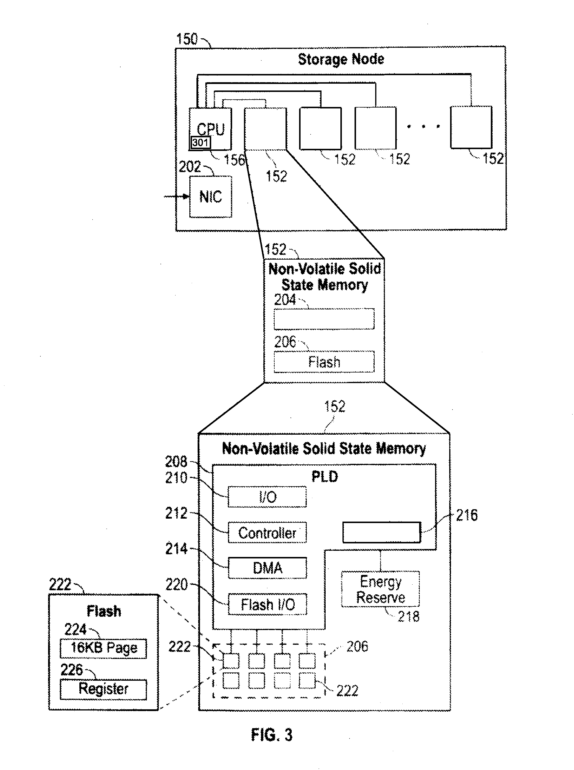
[0043] FIG. 3 is a multiple level block diagram, showing contents of a storage node 150 and contents of a non-volatile solid state storage 152 of the storage node 150. Data is communicated to and from the storage node 150 by a network interface controller (NIC) 202 in some embodiments. Each storage node 150 has a CPU 156, and one or more non-volatile solid state storage 152, as discussed above. CPU 156 includes space accounting logic 301. Space accounting logic may be embodied as a software module that monitors space used in the system and provides attributes for compression/volumes for the data in the system. In some embodiments, space accounting logic 301 includes a space detector that detects imbalances through the evaluation/monitoring of write groups and initiating an event when an imbalance is detected as described in more detail below. Moving down one level in FIG. 3, each non-volatile solid state storage 152 has a relatively fast non-volatile solid state memory, such as nonvolatile random access memory (NVRAM) 204, and flash memory 206. In some embodiments, NVRAM 204 may be a component that does not require program/erase cycles (DRAM, MRAM, PCM), and can be a memory that can support being written vastly more often than the memory is read from. Moving down another level in FIG. 3, the NVRAM 204 is implemented in one embodiment as high speed volatile memory, such as dynamic random access memory (DRAM) 216, backed up by energy reserve 218. Energy reserve 218 provides sufficient electrical power to keep the DRAM 216 powered long enough for contents to be transferred to the flash memory 206 in the event of power failure. In some embodiments, energy reserve 218 is a capacitor, super-capacitor, battery, or other device, that supplies a suitable supply of energy sufficient to enable the transfer of the contents of DRAM 216 to a stable storage medium in the case of power loss. The flash memory 206 is implemented as multiple flash dies 222, which may be referred to as packages of flash dies 222 or an array of flash dies 222. It should be appreciated that the flash dies 222 could be packaged in any number of ways, with a single die per package, multiple dies per package (i.e. multichip packages), in hybrid packages, as bare dies on a printed circuit board or other substrate, as encapsulated dies, etc. In the embodiment shown, the non-volatile solid state storage 152 has a controller 212 or other processor, and an input output (I/O) port 210 coupled to the controller 212. I/O port 210 is coupled to the CPU 156 and/or the network interface controller 202 of the flash storage node 150. Flash input output (I/O) port 220 is coupled to the flash dies 222, and a direct memory access unit (DMA) 214 is coupled to the controller 212, the DRAM 216 and the flash dies 222. In the embodiment shown, the I/O port 210, controller 212, DMA unit 214 and flash I/O port 220 are implemented on a programmable logic device (PLD) 208, e.g., a field programmable gate array (FPGA). In this embodiment, each flash die 222 has pages, organized as sixteen kB (kilobyte) pages 224, and a register 226 through which data can be written to or read from the flash die 222. In further embodiments, other types of solid-state memory are used in place of, or in addition to flash memory illustrated within flash die 222.
[0044] Storage clusters 160, in various embodiments as disclosed herein, can be contrasted with storage arrays in general. The storage nodes 150 are part of a collection that creates the storage cluster 160. Each storage node 150 owns a slice of data and computing required to provide the data. Multiple storage nodes 150 cooperate to store and retrieve the data. Storage memory or storage devices, as used in storage arrays in general, are less involved with processing and manipulating the data. Storage memory or storage devices in a storage array receive commands to read, write, or erase data. The storage memory or storage devices in a storage array are not aware of a larger system in which they are embedded, or what the data means. Storage memory or storage devices in storage arrays can include various types of storage memory, such as RAM, solid state drives, hard disk drives, etc. The storage units 152 described herein have multiple interfaces active simultaneously and serving multiple purposes. In some embodiments, some of the functionality of a storage node 150 is shifted into a storage unit 152, transforming the storage unit 152 into a combination of storage unit 152 and storage node 150. Placing computing (relative to storage data) into the storage unit 152 places this computing closer to the data itself. The various system embodiments have a hierarchy of storage node layers with different capabilities. By contrast, in a storage array, a controller owns and knows everything about all of the data that the controller manages in a shelf or storage devices. In a storage cluster 160, as described herein, multiple controllers in multiple storage units 152 and/or storage nodes 150 cooperate in various ways (e.g., for erasure coding, data sharding, metadata communication and redundancy, storage capacity expansion or contraction, data recovery, and so on).
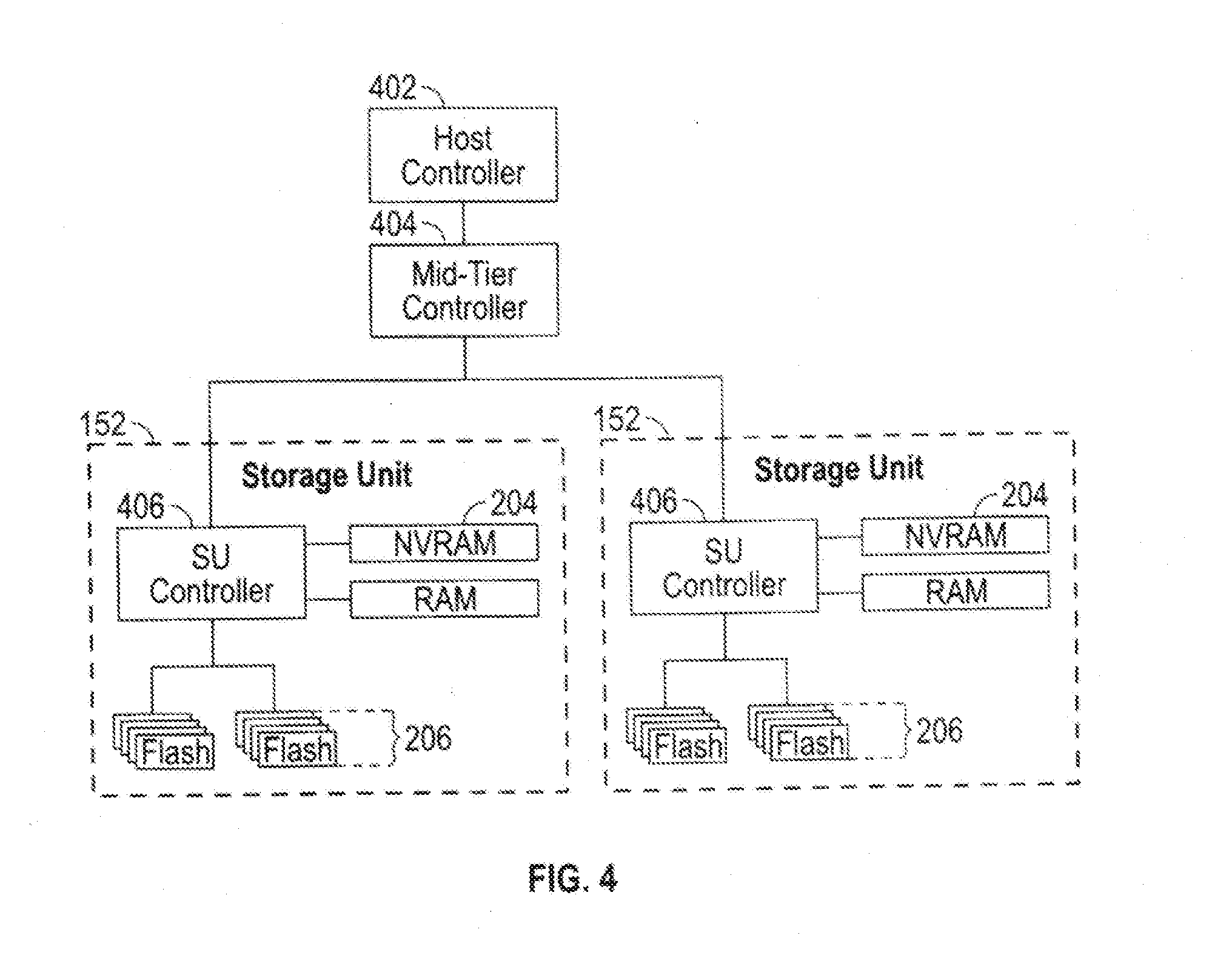
[0045] FIG. 4 shows a storage server environment, which uses embodiments of the storage nodes 150 and storage units 152 of FIGS. 1-3. In this version, each storage unit 152 has a processor such as controller 212 (see FIG. 3), an FPGA (field programmable gate array), flash memory 206, and NVRAM 204 (which may be super-capacitor backed DRAM 216, see FIG. 3) on a PCIe (peripheral component interconnect express) board in a chassis 138 (see FIG. 1). The storage unit 152 may be implemented as a single board containing storage, and may be the largest tolerable failure domain inside the chassis. In some embodiments, up to two storage units 152 may fail and the device will continue with no data loss.
[0046] The physical storage is divided into named regions based on application usage in some embodiments. The NVRAM 204 is a contiguous block of reserved memory in the storage unit 152 DRAM 216, and is backed by NAND flash. NVRAM 204 is logically divided into multiple memory regions written for two as spool (e.g., spool_region). Space within the NVRAM 204 spools is managed by each authority 512 independently. Each device provides an amount of storage space to each authority 512. That authority 512 further manages lifetimes and allocations within that space. Examples of a spool include distributed transactions or notions. When the primary power to a storage unit 152 fails, onboard super-capacitors provide a short duration of power hold up. During this holdup interval, the contents of the NVRAM 204 are flushed to flash memory 206. On the next power-on, the contents of the NVRAM 204 are recovered from the flash memory 206.
[0047] As for the storage unit controller, the responsibility of the logical "controller" is distributed across each of the blades containing authorities 512. This distribution of logical control is shown in FIG. 4 as a host controller 402, mid-tier controller 404 and storage unit controller(s) 406. Management of the control plane and the storage plane are treated independently, although parts may be physically co-located on the same blade. Each authority 512 effectively serves as an independent controller. Each authority 512 provides its own data and metadata structures, its own background workers, and maintains its own lifecycle.
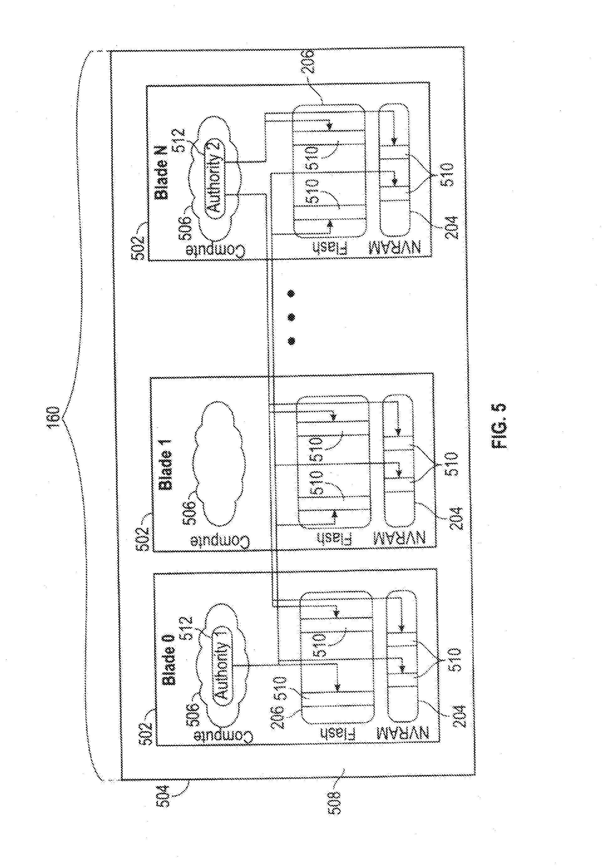
[0048] FIG. 5 is a blade 502 hardware block diagram, showing a control plane 504, compute and storage planes 506, 508, and authorities 512 interacting with underlying physical resources to perform distributed transactions, using embodiments of the storage nodes 150 and storage units 152 of FIGS. 1-3 in the storage server environment of FIG. 4. The control plane 504 is partitioned into a number of authorities 512 which can use the compute resources in the compute plane 506 to run on any of the blades 502. The storage plane 508 is partitioned into a set of devices, each of which provides access to flash 206 and NVRAM 204 resources. In the compute and storage planes 506, 508 of FIG. 5, the authorities 512 interact with the underlying physical resources (i.e., devices). From the point of view of an authority 512, its resources are striped over all of the physical devices. From the point of view of a device, it provides resources to all authorities 512, irrespective of where the authorities happen to run. In order to communicate and represent the ownership of an authority 402, including the right to record persistent changes on behalf of that authority 402, the authority 402 provides some evidence of authority ownership that can be independently verifiable. A token is employed for this purpose and function in one embodiment, although other techniques are readily devised.
[0049] Still referring to FIG. 5, each authority 512 has allocated or has been allocated one or more partitions 510 of storage memory in the storage units 152, e.g. partitions 510 in flash memory 206 and NVRAM 204. Each authority 512 uses those allocated partitions 510 that belong to it, for writing or reading user data. Authorities can be associated with differing amounts of physical storage of the system. For example, one authority 512 could have a larger number of partitions 510 or larger sized partitions 510 in one or more storage units 152 than one or more other authorities 512. The above-described storage systems and storage clusters, and variations thereof, and various further storage systems and storage clusters are suitable for the mechanism for rebuilding/evacuating data and as the migration of the data occurs the method is capable of dynamically or adaptively selecting mechanism for the migration based on monitoring space availability/usage for the system, as described below. It should be appreciated that, although described with flash memory, the teachings herein are applicable to other types of solid-state memory and other types of storage memory.
[0050] Migration of data from one failure domain, which may be referred to as a writegroup, in a flash array involves considering a number of factors:
[0051] a) Space available in the entire array,
[0052] Blindly migrating data (in the presence of more incoming data) can fill the array beyond comfortable limits, causing undue garbage collection pressure and other performance anomalies.
[0053] b) Balancing space available in individual failure domains. As noted above a failure domain may be referred to as a writegroup in some embodiments.
[0054] An imbalanced migration can cause some write groups to be fuller than other writegroups, causing performance hotspots for reads. Write hotspots can also be created due to the allocator preferring some writegroups over other.
[0055] c) Efficiency of migration.
[0056] Migrated data (depending on the method chosen) may migrate dead/overwritten data in addition to live data.
[0057] The embodiments provide a writegroup space aware mechanism, writegroup balanced migration. Migration typically has two methods available: [0058] RAID rebuild. This mechanism copies bits over, and includes live as well as overwritten data. No space efficiency is achieved, however the operation is faster, as it does not involve testing the data for liveness while migrating. Since rebuild cannot change the structure/geometry of segments, target write groups for this data can only be same or larger writegroups. [0059] GC (garbage collection) move. This mechanism analyses the data, cross referencing it with system metadata to check of liveness, and then picking up and recomposing the live-only data into new segments. This is more space efficient as a GC move will only migrate live data, but is more expensive in terms of central processing unit (CPU)/dynamic random access memory (DRAM) resources. Since entire new segments are composed, the target writegroup can be any (even smaller) write groups that are chosen by the system allocator. That is, deduplication is integrated into the migration mechanism with the inclusion of a GC move. It should be appreciated that while the embodiments include the above two migration mechanism, other migration techniques or mechanisms may be integrated with the embodiments, as the embodiments are not limited to the above two techniques.
[0060] In a system composed of write groups of different sizes, the migration proceeds as follows:
[0061] 1. Start off by using rebuild (favor performance over space efficiency).
[0062] 2. As migration proceeds, compatible writegroups will get fuller more quickly than incompatible writegroups. A space monitoring module signals imbalance in space usage of the writegroups.
[0063] 3. Migration reacts to the imbalance signal, by switching some segment migration using GC. If the signal persists, a majority (up to 100%) of the migrated segments may move over to using the GC method.
[0064] 4. At any time, if the space usage of the entire array approaches a set threshold, migration just stalls, until the array is empty enough to proceed.
[0065] 5. Also, at any time, GC method kicks in if space of the entire array goes above a soft threshold.
[0066] An aspect of this migration is that it considers side effects due to varying incoming workloads automatically. An incoming workload can: [0067] a) Help restore balance from imbalance: New writes are assigned the emptiest writegroups by an allocator, helping to restore balanced writegroups. [0068] b) Triggering space efficient migration by introducing imbalance: Sudden workloads will cause an imbalance, causing migration to tilt towards space efficient GC, attempting to restore balance.
[0069] FIG. 6 is a block diagram of an embodiment of the space accounting logic 301 shown in FIG. 3. Space accounting logic 301 could be implemented in hardware, firmware, software executing on a processor, or combination thereof, in a storage system, for example a high-availability controller-based storage system, or in a storage cluster, for example in a storage node 150, or across storage nodes 150 as distributed software or logic. Further embodiments in various types of storage systems, including storage arrays in storage clusters, are readily devised in keeping with the teachings herein. In some embodiments, each of the storage nodes 150 of a storage cluster 160 has space accounting logic 301. A space detector 602 monitors memory space, more specifically the amount of storage memory in blades, storage nodes 150 or storage units 152, solid-state drives or other storage devices, etc., or the entire system, that is occupied by data or is available for writing data. In various embodiments, the space accounting logic 301 could count or determine erased blocks, written blocks, written pages or total amount of data written to a storage unit 152, for example using one or more counters, score boarding, or other data structure and tracking erasures and writing, or by directly detecting blocks that have no written data. In some embodiments, the space accounting logic 301 can track write groups, for example by failure domain. For example, the space accounting logic 301 could report on storage usage as a percentage of size of write groups, space utilization from fullest to emptiest write group or failure domain, or other aspects of storage space utilization and availability.
[0070] Still referring to FIG. 6, a migration enable module 604 in the space accounting logic 301 is coupled to the space detector 602, and determines whether migration should proceed with a RAID rebuild, as directed by a RAID rebuild module 606, or by a garbage collection move, as directed by a garbage collection move module 608. This decision is symbolized in FIG. 6 by a switch, which could be implemented as a software decision, or in hardware or firmware.
[0071] FIG. 7 is an action diagram depicting migration from a storage unit 152, along with an incoming workload 704, directed by the space accounting logic 301 and an allocator 702 in a storage node 150. In the scenario shown here, the middle storage unit 152 is being evacuated, for example to free up the storage unit 152 for replacement or upgrade. Data is being migrated out of the storage unit 152, along a migration path 706 to another storage unit 152. An alternate migration path 708 is shown in dashed lines. Other evacuation and migration scenarios are readily developed in keeping with the teachings herein.
[0072] As depicted in FIG. 7, the space accounting logic 301 monitors the space usage of multiple write groups or failure domains in the storage units 152. This is performed using the space detector 602 shown in FIG. 6. Initially, the migration enable module 604 in the space accounting logic 301 selects the RAID rebuild module 606, and directs a migration using RAID rebuild. Based on the fullness of the compatible write groups versus incompatible write groups, the migration can dynamically or adaptively switch to garbage collection move, as directed by the migration enable module 604 using the garbage collection move module 608. For example, if the compatible write groups become more full than the incompatible write groups, the migration enable module 604 could direct a garbage collection move. This could be done with a percentage of the moves of the migration, or all of the moves of the migration, in various embodiments. In some embodiments, the percentage of the moves of the migration that are directed to a garbage collection move is a variable percentage, based on the relative amount of fullness of the compatible write groups in comparison with the fullness of the incompatible write groups. In some embodiments, there is a threshold, and all of the moves are switched from RAID rebuild to garbage collection move once the threshold is exceeded. Also, if the space of the entire array is above a threshold, in some embodiments, the migration switches to garbage collection move. In some embodiments, if the space usage of the entire storage system reaches a threshold, migration is stalled until the array is empty enough to proceed (i.e., the space usage drops below the threshold). In some embodiments, hysteresis is used for one or more thresholds.
[0073] Still referring to FIG. 7, the storage node 150 distributes writes from the incoming workload 704 in accordance with an allocator 702. The allocator 702, in some embodiments, assigns new writes to the emptiest write groups, which helps to restore balanced write groups. During a migration, the system can switch back and forth between RAID rebuild and garbage collection move for the migration, to restore or maintain balance between compatible write groups and incompatible write groups. As noted above, other migration techniques may be integrated with the embodiments.
[0074] FIG. 8 is a flow diagram of a method for evacuating or migrating data from a write group. The method can be practiced by a storage node and storage units of a storage cluster as described herein, in various embodiments. Also, the method can be practiced by a processor in a storage system. In an action 802, a migration is started from a first write group of a failure domain in a storage system to a second write group, using RAID rebuild. In an action 804, space usage of write groups is monitored. In a determination action 806, it is determined whether compatible write groups are more full than incompatible write groups. In further embodiments some other threshold could be applied to this determination. If the answer in the determination action 806 is no, the migration is continued using RAID rebuild, in the action 808. If the answer in the determination action 806 is yes, the migration is switched to using garbage collection move, in the action 810.
[0075] Both of the actions 808, 810 rejoin the flow at the decision action 812, where it is determined whether the space usage of the storage system is below a threshold. If the answer to the determination action 812 is yes, the space usage is below threshold, flow continues with the action 816. If the answer to the decision action 812 is no, the space usage is not below the threshold (i.e., the space usage is at or above the threshold), the migration is stalled in the action 814. Both of the actions 812, 814 rejoin the flow at the decision action 816, in which it is determined whether there are new writes from an incoming workload. If not, flow proceeds back to the action 804, to continue monitoring space usage of write groups. If there are new writes from the incoming workload, flow proceeds to the action 818, in which the allocator assigns new writes to the emptiest write groups. Flow loops back to the action 804, to continue monitoring space usage of write groups.
[0076] In variations of this flow, decision actions could be performed in different orders or combined. In a further variation, the portions of the migration could be continued using RAID rebuild while other portions continue using migration, proportional to or otherwise determined by a ratio or comparison of the fullness of compatible write groups relative to incompatible write groups. Thus, the mechanism can be employed in a dynamic and/or adaptive manner in some embodiments. It should be appreciated that the embodiments through the inclusion of the garbage collection move integrate and improve deduplication through the elimination of overwritten data.
[0077] FIG. 9 is a system diagram of a data storage array 908, which has a high-availability controller pair in accordance with some embodiments. Multiple storage devices 912 are coupled to the high-availability controller pair 906. These could be solid-state drives (SSD), hard disk drives (HDD), optical drives or other types of storage memory. A network interface 910 couples the data storage array 908 to a network, which could be wired or wireless. For convenience, the controllers 902, 904 of the high-availability controller pair 906 are labeled "controller A" (for the left-most controller 902) and "controller B" (for the right-most controller 904), although these labels are arbitrary and various names, numberings or symbols could be used to identify them. Either of the controllers 902, 904 can communicate with any of the storage devices 912 (when communicative), for example via one or more busses or network connections.
[0078] FIG. 10 depicts copying live and dead data in a migration. Embodiments of a storage system that adaptively adjusts between differing migration techniques can apply the copying of both live and dead data under specified conditions. In the example scenario shown in FIG. 10, a migration source 1002 of storage memory within the storage system has a combination of erased 1006, live data 1008, and dead data 1016 in memory. This is typical of flash memory that has been in use in a storage system. Generally, flash memory starts out in the erased 1006 state, with all blocks erased. The storage system writes data to addresses in memory, which is then live data 1008 since the data is in current use in the storage system. Gradually, erased 1006 locations become replaced with live data 1008 as the system continues to store data. Some operations overwrite live data 1008, which then becomes dead data 1016. For example, a file system command to delete a file, an editing command to replace data, a database command to update data, and other commands that obsolete or replace data result in the discarding or retiring of live data 1008. In physical solid-state memory such as flash, this is handled by recording that the data at specified addresses is dead data 1006, such as by flagging or otherwise noting this status in metadata.
[0079] Continuing with FIG. 10, in action 1010 to write new data, append, is performed when the system writes new data to physical memory in an append-based system. The new live data 1012 is written into the memory, into a formerly erased 1006 location. The mechanism for overwritten dead data 1016 is for the system to retire former live data 1008 that is overwritten and becomes dead data 1016, and to write the new live data 1012 to a formerly erased 1006 location, rather than attempting to write the new live data 1012 into a dead data 1016 location. This is because flash memory has a block erase mechanism, and the entire block is erased before formerly written locations can be written again. In action 1014, read data, is performed when the system reads data (e.g., to access user data or to access metadata). The live data 1008 of interest is read out. Generally, the system considers dead data 1016, i.e., data that has been overwritten, as storage overhead that is useless for further data storage until recovered by block erasure, for example in a garbage collection process.
[0080] Continuing with the scenario depicted in FIG. 10, once the migration source 1002 and migration destination 1004 are identified in the storage memory, the dead data 1016 and the live data 1008 are copied from the migration source 1002 to the migration destination 1004. One way to achieve this mechanism is with copying of every bit, i.e., a bit for bit copy, for example using raw page reads of entire pages or an entire block of flash memory, from the migration source 1002 to the migration destination 1004. In some embodiments, this is performed as a RAID rebuild, in which the data is moved from the migration source 1002 to the migration destination 1004, with appropriate updating to metadata, so that RAID accesses can then access the migrated data at the migration destination 1004 without having to change to a different level of redundancy or error correction coding. In other words, a RAID rebuild preserves data protection for all of the bits across existing data stripes, permitting access to the migrated bits at the new location in the migration destination 1004.
[0081] FIG. 11 depicts copying only live data 1008 in a garbage collection data move.
[0082] Embodiments of a storage system that adaptively adjusts between differing migration techniques can apply the copying of live data 1008 under specified conditions. Here, the live data 1008 is moved from the migration source 1002 to the migration destination 1004, but the dead data 1016 is not moved. The system can determine which data is live versus dead by consulting metadata in some embodiments. An action 1018, erase block, reclaim, after migrating live data, is performed when the system completes migrating the live data and reclaims a block of flash memory. After erasing the block, all of the locations are erased 1006, with neither live data 1008 nor dead data 1016 remaining in that erased block. Garbage collection, in flash memory, is a mechanism for keeping live data, and recovering memory with dead data 1016 that has been overwritten (e.g., in the append process described above with reference to FIG. 10). Recovered blocks of flash memory are then available for writing new data, or could be part of memory that is removed and/or replaced or upgraded.
[0083] With reference to FIGS. 1-11 various embodiments of storage systems that have storage space detection or monitoring, two or more migration mechanisms, and decision-making among the migration mechanisms in accordance with the storage space detection or monitoring are described below in various scenarios. One such system has multiple failure domains, and each failure domain is referred to as a write group. Each write group has data protection. Depending on scale, the system might have one, ten or twenty write groups, or more, and as data comes in, the data is RAID protected and written within a write group. This could be implemented, for example, using two or more processors in a high-availability controller-based storage system, as described with reference to FIG. 9. The system attempts to keep write groups balanced, e.g., with comparable storage memory space used and storage memory space available across the write groups. It should be appreciated that under this mechanism hotspots, in which read performance is affected by bottlenecks from a read load that concentrates reads on one write group, do not develop.
[0084] One or more of the write groups is evacuated when it is time to retire or upgrade some of the hardware in a flash array. For example, older storage solid-state drives may be smaller and slower, and newer, faster, higher capacity solid-state drives become available. In order to evacuate a write group, data is migrated from that write group to a compatible write group, or in some embodiments to multiple compatible write groups. The embodiments can monitor space usage across write groups and switch migration between migrating live data 1008 and dead data 1016, as shown in FIG. 10, and migrating only live data 1008, as shown in FIG. 11, according to whether the balance or imbalance in space usage across the write groups is or is not within a threshold. More specifically, if the space detector 602 indicates there is balance across the write groups, to within a balance threshold, the system can migrate both live and dead data. If the space detector 602 indicates there is imbalance across the write groups, i.e., balance is not within the balance threshold, the system migrates only the live data 1008 as discussed with reference to FIG. 8. Migrating live data 1008 and dead data 1016 consumes less computing resources and mainly involves reading and writing, but consumes more storage memory at the migration destination 1004. Migrating only live data 1008 consumes more computing resources, because it involves determining which data is live data 1008 as opposed to dead data 1016, but consumes less storage memory at the migration destination 1004 and is therefore more space efficient.
[0085] Moving data only to compatible write groups, as happens when both live data 1008 and dead data 1016 are moved in a RAID rebuild, can create an imbalance across the write groups, because data is accumulating only in the compatible write groups and not accumulating in the incompatible write groups. When this imbalance occurs, the system switches to the garbage collection migration, moving only live data 1008, and the allocator 702 (see FIG. 7) allocates storage space from write groups that are not targets for an evacuation, i.e., allocates from incompatible write groups). It should be appreciated that this helps with restoring the balance in the space used versus space available across the write groups. Once balance is restored, the system can switch back to moving both live data 1008 and dead data 1016. Switching can continue in a dynamic manner.
[0086] Another such system is a storage cluster 160, with blades and storage nodes 150. Each blade has a storage node 150, and some number of storage units 152. This system could use the space accounting logic 301 to monitor storage memory usage across the blades, nodes 150 and/or storage units 152. Various upgrade mechanisms involve replacement of one or more blades, introduction of one or more new blades, or upgrading to a new chassis with new blades. Migration could involve remapping the data to new locations in one or more new blades or the new chassis. In some embodiments, the remapping can use bit for bit data migration, and the system can switch to or from garbage collection move, according to memory storage space utilization balance or imbalance across the blades, storage node 150 or storage units 152. Targeted remapping allows reuse of portions of the mapping with remapping at one or more levels of indirection and is thus an efficient method of transfer.
[0087] Yet another system that could benefit from dynamic switching of migration mechanisms based on balance or imbalance in storage utilization is a storage system, for example a storage array, that uses solid-state drives. The system could monitor memory storage space usage and memory storage space availability across solid-state drives, and switch back and forth between migrating live and dead data versus migrating only live data, to preserve balance of memory utilization across the solid-state drives. Space accounting logic 301 could be implemented in a storage controller for the storage array.
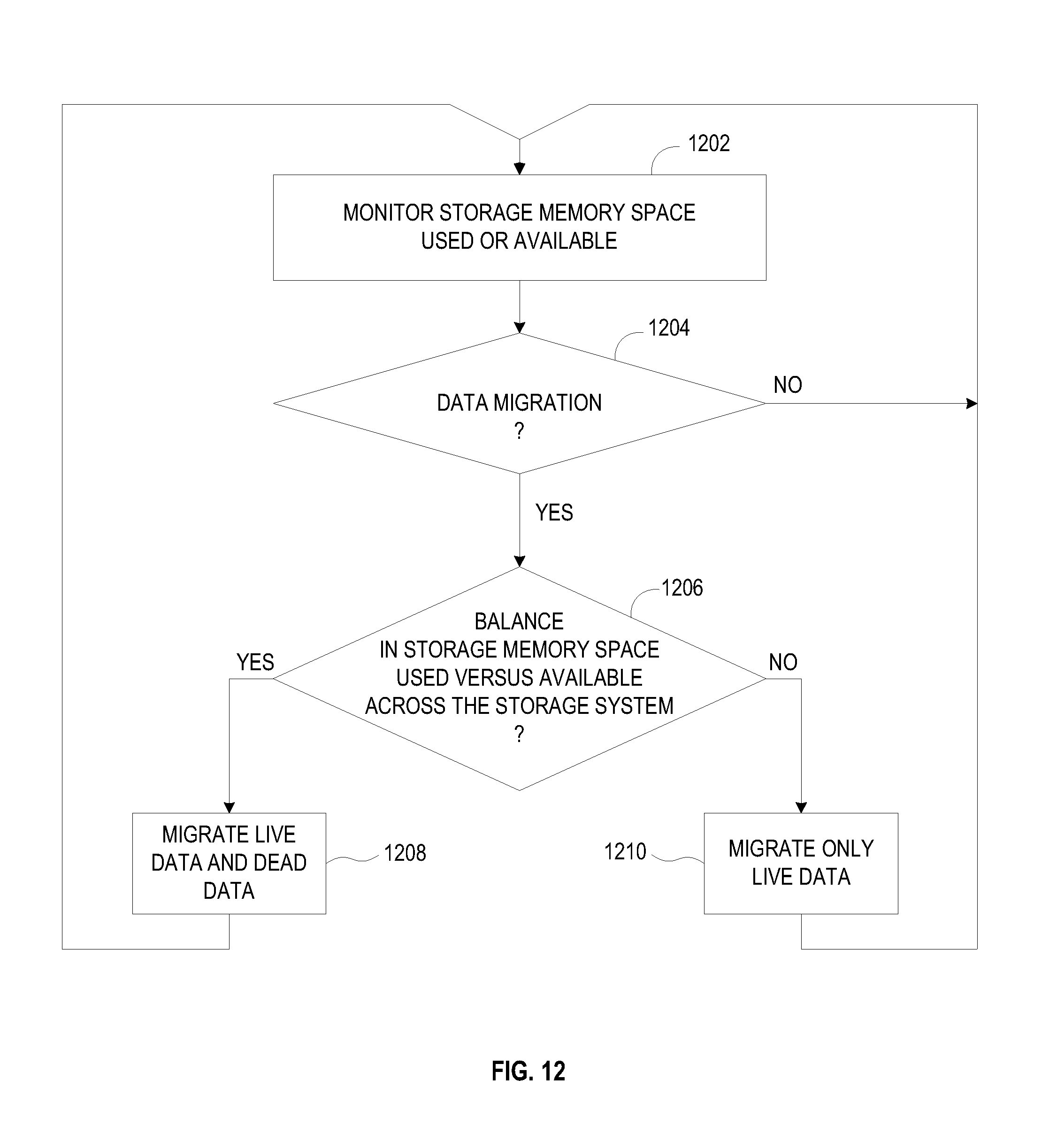
[0088] FIG. 12 is a flow diagram of a method of data migration within a storage system. The method can be practiced by various storage systems, more specifically by one or more processors in a storage system. In an action 1202, the storage memory space used or available is monitored. This could be monitored as storage memory space used in the entire storage system, or in each of various components or portions of storage memory, and could be expressed as values of parameters, ratios, or relative to a threshold, etc. In a determination action 1204, it is determined whether there is or should be a data migration. If the answer is no data migration, the flow branches back to the action 1202, in order to continue monitoring storage memory space. If the answer is yes, there is a data migration, flow proceeds to the determination action 1206.
[0089] Continuing with FIG. 12, in the determination action 1206, is determined whether there is balance in storage memory space, of storage memory space used versus storage memory space available, across the storage system. For example, this could be a determination of balance or imbalance in total amount of storage memory space used versus total amount of storage memory space available for the system, or balance or imbalance across blades, storage nodes, storage units, write groups, or other portions of storage memory. In some embodiments, this could be determined through comparison to a threshold. In some embodiments, the threshold could be variable, or have hysteresis as discussed above. If the answer is yes, there is balance, flow proceeds to the action 1208, in which live data and dead data are migrated. If the answer is no, there is imbalance, and flow proceeds to the action 1210, in which only live data is migrated. Flow from the actions 1208 and 1210 proceeds back to the action 1202, to continue monitoring storage memory space and, if the balance or imbalance changes, switching the data migration technique. This dynamic/adaptive switching can continue until the data migration is complete.
[0090] It should be appreciated that the methods described herein may be performed with a digital processing system, such as a conventional, general-purpose computer system. Special purpose computers, which are designed or programmed to perform only one function may be used in the alternative. FIG. 13 is an illustration showing an exemplary computing device which may implement the embodiments described herein. The computing device of FIG. 13 may be used to perform embodiments of the functionality for PROCESSES in accordance with some embodiments. The computing device includes a central processing unit (CPU) 1301, which is coupled through a bus 1305 to a memory 1303, and mass storage device 1307. Mass storage device 1307 represents a persistent data storage device such as a floppy disc drive or a fixed disc drive, which may be local or remote in some embodiments. The mass storage device 1307 could implement a backup storage, in some embodiments. Memory 1303 may include read only memory, random access memory, etc. Applications resident on the computing device may be stored on or accessed via a computer readable medium such as memory 1303 or mass storage device 1307 in some embodiments. Applications may also be in the form of modulated electronic signals modulated accessed via a network modem or other network interface of the computing device. It should be appreciated that CPU 1301 may be embodied in a general-purpose processor, a special purpose processor, or a specially programmed logic device in some embodiments.
[0091] Display 1311 is in communication with CPU 1301, memory 1303, and mass storage device 1307, through bus 1305. Display 1311 is configured to display any visualization tools or reports associated with the system described herein. Input/output device 1309 is coupled to bus 1305 in order to communicate information in command selections to CPU 1301. It should be appreciated that data to and from external devices may be communicated through the input/output device 1309. CPU 1301 can be defined to execute the functionality described herein to enable the functionality described with reference to FIGS. 1-12. The code embodying this functionality may be stored within memory 1303 or mass storage device 1307 for execution by a processor such as CPU 1301 in some embodiments. The operating system on the computing device may be iOS.TM., MS-WINDOWS.TM., OS/2.TM., UNIX.TM., LINUX.TM., or other known operating systems. It should be appreciated that the embodiments described herein may also be integrated with a virtualized computing system implemented with physical computing resources.
[0092] Detailed illustrative embodiments are disclosed herein. However, specific functional details disclosed herein are merely representative for purposes of describing embodiments. Embodiments may, however, be embodied in many alternate forms and should not be construed as limited to only the embodiments set forth herein.
[0093] It should be understood that although the terms first, second, etc. may be used herein to describe various steps or calculations, these steps or calculations should not be limited by these terms. These terms are only used to distinguish one step or calculation from another. For example, a first calculation could be termed a second calculation, and, similarly, a second step could be termed a first step, without departing from the scope of this disclosure. As used herein, the term "and/or" and the "/" symbol includes any and all combinations of one or more of the associated listed items.
[0094] As used herein, the singular forms "a", "an" and "the" are intended to include the plural forms as well, unless the context clearly indicates otherwise. It will be further understood that the terms "comprises", "comprising", "includes", and/or "including", when used herein, specify the presence of stated features, integers, steps, operations, elements, and/or components, but do not preclude the presence or addition of one or more other features, integers, steps, operations, elements, components, and/or groups thereof. Therefore, the terminology used herein is for the purpose of describing particular embodiments only and is not intended to be limiting.
[0095] It should also be noted that in some alternative implementations, the functions/acts noted may occur out of the order noted in the figures. For example, two figures shown in succession may in fact be executed substantially concurrently or may sometimes be executed in the reverse order, depending upon the functionality/acts involved.
[0096] With the above embodiments in mind, it should be understood that the embodiments might employ various computer-implemented operations involving data stored in computer systems. These operations are those requiring physical manipulation of physical quantities. Usually, though not necessarily, these quantities take the form of electrical or magnetic signals capable of being stored, transferred, combined, compared, and otherwise manipulated. Further, the manipulations performed are often referred to in terms, such as producing, identifying, determining, or comparing. Any of the operations described herein that form part of the embodiments are useful machine operations. The embodiments also relate to a device or an apparatus for performing these operations. The apparatus can be specially constructed for the required purpose, or the apparatus can be a general-purpose computer selectively activated or configured by a computer program stored in the computer. In particular, various general-purpose machines can be used with computer programs written in accordance with the teachings herein, or it may be more convenient to construct a more specialized apparatus to perform the required operations.
[0097] A module, an application, a layer, an agent or other method-operable entity could be implemented as hardware, firmware, or a processor executing software, or combinations thereof. It should be appreciated that, where a software-based embodiment is disclosed herein, the software can be embodied in a physical machine such as a controller. For example, a controller could include a first module and a second module. A controller could be configured to perform various actions, e.g., of a method, an application, a layer or an agent.
[0098] The embodiments can also be embodied as computer readable code on a tangible non-transitory computer readable medium. The computer readable medium is any data storage device that can store data, which can be thereafter read by a computer system. Examples of the computer readable medium include hard drives, network attached storage (NAS), read-only memory, random-access memory, CD-ROMs, CD-Rs, CD-RWs, magnetic tapes, and other optical and non-optical data storage devices. The computer readable medium can also be distributed over a network coupled computer system so that the computer readable code is stored and executed in a distributed fashion. Embodiments described herein may be practiced with various computer system configurations including hand-held devices, tablets, microprocessor systems, microprocessor-based or programmable consumer electronics, minicomputers, mainframe computers and the like. The embodiments can also be practiced in distributed computing environments where tasks are performed by remote processing devices that are linked through a wire-based or wireless network.
[0099] Although the method operations were described in a specific order, it should be understood that other operations may be performed in between described operations, described operations may be adjusted so that they occur at slightly different times or the described operations may be distributed in a system which allows the occurrence of the processing operations at various intervals associated with the processing.
[0100] In various embodiments, one or more portions of the methods and mechanisms described herein may form part of a cloud-computing environment. In such embodiments, resources may be provided over the Internet as services according to one or more various models. Such models may include Infrastructure as a Service (IaaS), Platform as a Service (PaaS), and Software as a Service (SaaS). In IaaS, computer infrastructure is delivered as a service. In such a case, the computing equipment is generally owned and operated by the service provider. In the PaaS model, software tools and underlying equipment used by developers to develop software solutions may be provided as a service and hosted by the service provider. SaaS typically includes a service provider licensing software as a service on demand. The service provider may host the software, or may deploy the software to a customer for a given period of time. Numerous combinations of the above models are possible and are contemplated.
[0101] Various units, circuits, or other components may be described or claimed as "configured to" perform a task or tasks. In such contexts, the phrase "configured to" is used to connote structure by indicating that the units/circuits/components include structure (e.g., circuitry) that performs the task or tasks during operation. As such, the unit/circuit/component can be said to be configured to perform the task even when the specified unit/circuit/component is not currently operational (e.g., is not on). The units/circuits/components used with the "configured to" language include hardware--for example, circuits, memory storing program instructions executable to implement the operation, etc. Reciting that a unit/circuit/component is "configured to" perform one or more tasks is expressly intended not to invoke 35 U.S.C. 112, sixth paragraph, for that unit/circuit/component. Additionally, "configured to" can include generic structure (e.g., generic circuitry) that is manipulated by software and/or firmware (e.g., an FPGA or a general-purpose processor executing software) to operate in manner that is capable of performing the task(s) at issue. "Configured to" may also include adapting a manufacturing process (e.g., a semiconductor fabrication facility) to fabricate devices (e.g., integrated circuits) that are adapted to implement or perform one or more tasks.
[0102] The foregoing description, for the purpose of explanation, has been described with reference to specific embodiments. However, the illustrative discussions above are not intended to be exhaustive or to limit the invention to the precise forms disclosed. Many modifications and variations are possible in view of the above teachings. The embodiments were chosen and described in order to best explain the principles of the embodiments and its practical applications, to thereby enable others skilled in the art to best utilize the embodiments and various modifications as may be suited to the particular use contemplated. Accordingly, the present embodiments are to be considered as illustrative and not restrictive, and the invention is not to be limited to the details given herein, but may be modified within the scope and equivalents of the appended claims.
* * * * *
D00000
D00001
D00002
D00003
D00004
D00005
D00006
D00007
D00008
D00009
D00010
D00011
D00012

XML
uspto.report is an independent third-party trademark research tool that is not affiliated, endorsed, or sponsored by the United States Patent and Trademark Office (USPTO) or any other governmental organization. The information provided by uspto.report is based on publicly available data at the time of writing and is intended for informational purposes only.
While we strive to provide accurate and up-to-date information, we do not guarantee the accuracy, completeness, reliability, or suitability of the information displayed on this site. The use of this site is at your own risk. Any reliance you place on such information is therefore strictly at your own risk.
All official trademark data, including owner information, should be verified by visiting the official USPTO website at www.uspto.gov. This site is not intended to replace professional legal advice and should not be used as a substitute for consulting with a legal professional who is knowledgeable about trademark law.