Apparatuses for Controlling Heat for Rapid Thermal Processing of Carbonaceous Material and Methods for the Same
Kulprathipanja; Sathit ; et al.
U.S. patent application number 16/026367 was filed with the patent office on 2019-06-06 for apparatuses for controlling heat for rapid thermal processing of carbonaceous material and methods for the same. The applicant listed for this patent is Ensyn Renewables, Inc.. Invention is credited to Sathit Kulprathipanja, Daniel N. Myers, Paolo Palmas.
| Application Number | 20190170347 16/026367 |
| Document ID | / |
| Family ID | 47911644 |
| Filed Date | 2019-06-06 |


| United States Patent Application | 20190170347 |
| Kind Code | A1 |
| Kulprathipanja; Sathit ; et al. | June 6, 2019 |
Apparatuses for Controlling Heat for Rapid Thermal Processing of Carbonaceous Material and Methods for the Same
Abstract
Embodiments of apparatuses and methods for controlling heat for rapid thermal processing of carbonaceous material are provided herein. The apparatus comprises a reactor, a reheater for forming a fluidized bubbling bed comprising an oxygen-containing gas, inorganic heat carrier particles, and char and for burning the char into ash to form heated inorganic particles. An inorganic particle cooler is in fluid communication with the reheater. The inorganic particle cooler comprises a shell portion and a tube portion. The inorganic particle cooler is configured such that the shell portion receives a portion of the heated inorganic particles and the tube portion receives a cooling medium for indirect heat exchange with the portion of the heated inorganic particles to form partially-cooled heated inorganic particles.
| Inventors: | Kulprathipanja; Sathit; (Des Plaines, IL) ; Myers; Daniel N.; (Arlington Heights, IL) ; Palmas; Paolo; (Des Plaines, IL) | ||||||||||
| Applicant: |
|
||||||||||
|---|---|---|---|---|---|---|---|---|---|---|---|
| Family ID: | 47911644 | ||||||||||
| Appl. No.: | 16/026367 | ||||||||||
| Filed: | July 3, 2018 |
Related U.S. Patent Documents
| Application Number | Filing Date | Patent Number | ||
|---|---|---|---|---|
| 13240513 | Sep 22, 2011 | 10041667 | ||
| 16026367 | ||||
| Current U.S. Class: | 1/1 |
| Current CPC Class: | F27D 2009/0091 20130101; F23C 10/18 20130101; C10B 53/02 20130101; F23C 2206/103 20130101; Y02E 50/14 20130101; C10B 49/22 20130101; Y02E 50/10 20130101 |
| International Class: | F23C 10/18 20060101 F23C010/18; C10B 53/02 20060101 C10B053/02; C10B 49/22 20060101 C10B049/22 |
Claims
1. An apparatus for controlling heat for rapid thermal processing of carbonaceous material, the apparatus comprising: a reactor; a reheater in fluid communication with the reactor to receive inorganic heat carrier particles and char, wherein the reheater is configured to form a fluidized bubbling bed that comprises an oxygen-containing gas, the inorganic heat carrier particles, and the char and to operate at combustion conditions effective to burn the char into ash and heat the inorganic heat carrier particles to form heated inorganic particles; and an inorganic particle cooler in fluid communication with the reheater and comprising a shell portion and a tube portion that is disposed in the shell portion, wherein the inorganic particle cooler is configured such that the shell portion receives a portion of the heated inorganic particles and the tube portion receives a cooling medium for indirect heat exchange with the portion of the heated inorganic particles to form partially-cooled heated inorganic particles that are fluidly communicated to the reheater.
2. The apparatus according to claim 1, wherein the tube portion comprises a plurality of tubes each having an outer surface and at least one cooling fin that is disposed along the outer surface.
3. The apparatus according to claim 1, wherein the tube portion comprises a plurality of juxtaposed tubes that are spaced apart and longitudinally disposed substantially along a horizontal plane.
4. The apparatus according to claim 1, wherein the tube portion comprises a plurality of tubes each having an inner tube section and an outer tube section that is disposed around the inner tube section, each of the outer tube sections having an outer surface that contacts the portion of the heated inorganic particles for indirect heat exchange with the cooling medium.
5. The apparatus according to claim 4, wherein each of the plurality of tubes has an outer channel that is formed between the outer and inner tube sections and an inner channel that is formed in the inner tube section, and wherein the tube portion is configured such that the cooling medium is advanced through the outer channel for indirect heating with the portion of the heated inorganic particles to form a heated cooling medium and the heated cooling medium is advanced through the inner channel countercurrent to the cooling medium.
6. The apparatus according to claim 1, wherein the inorganic particle cooler comprises: an exchanger vessel comprising the shell and tube portions; a lift riser disposed downstream from the exchanger vessel; and a sand-air distributor disposed within the reheater downstream from the lift riser, and wherein the lift riser is configured to receive and fluidly communicate the partially-cooled heated inorganic particles to the sand-air distributor and the sand-air distributor is configured to distribute the partially-cooled heated inorganic particles in the reheater.
7. The apparatus according to claim 6, wherein the lift riser has a lower portion extending to an upper portion, the lower portion is configured to receive the partially-cooled heated inorganic particles and the upper portion is fluidly coupled to the sand-air distributor, and wherein the lift riser comprises an air nozzle that is positioned in the lower portion and that is configured to direct the partially-cooled heated inorganic particles through the lift riser from the lower portion to the upper portion for introduction to the sand-air distributor.
8. The apparatus according to claim 6, wherein the reheater has a lower section for containing the fluidized bubbling bed and comprises a gas distributor that is disposed in the lower section and that is configured to fluidly communicate the oxygen-containing gas to the fluidized bubbling bed, and wherein the sand-air distributor is disposed above the gas distributor.
9. The apparatus according to claim 8, wherein the inorganic particle cooler is fluidly coupled to the lower section of the reheater to receive the portion of the heated inorganic particles.
10. The apparatus according to claim 6, wherein the exchanger vessel further comprises an air distributor that is disposed downstream from the tube portion.
11. The apparatus according to claim 10, wherein the inorganic particle cooler further comprises at least one bubble breaking grating that is disposed upstream from the tube portion.
12. The apparatus according to claim 6, wherein the exchanger vessel further comprises a refractory lining that is disposed along an inner surface of the shell portion and that is configured to direct the portion of the heated inorganic particles into contact with the tube portion for indirect heat exchange with the cooling medium.
13. An apparatus for controlling heat for rapid thermal processing of carbonaceous material, the apparatus comprising: a reheater configured to contain a fluidized bubbling bed that comprises an oxygen-containing gas, inorganic heat carrier particles, and char and to operate at combustion conditions effective to burn the char into ash and heat the inorganic heat carrier particles to form heated inorganic particles; an inorganic particle cooler in fluid communication with the reheater and comprising a shell portion and a tube portion that is disposed in the shell portion, the inorganic particle cooler configured such that the shell portion receives a first portion of the heated inorganic particles and the tube portion receives a cooling medium for indirect heat exchange with the first portion of the heated inorganic particles to form first partially-cooled heated inorganic particles, wherein the reheater and the inorganic particle cooler are cooperatively configured to combine the first partially-cooled heated inorganic particles with a second portion of the heated inorganic particles in the reheater to form second partially-cooled heated inorganic particles; and a reactor in fluid communication with the reheater to receive the second partially-cooled heated inorganic particles for rapid pyrolysis of the carbonaceous material.
14. A method for controlling heat for rapid thermal processing of carbonaceous material, the method comprising the steps of: combining an oxygen-containing gas, inorganic heat carrier particles, and char at combustion conditions effective to burn the char into ash and heat the inorganic heat carrier particles to form heated inorganic particles; indirectly exchanging heat from a first portion of the heated inorganic particles that is advancing through a shell portion of an inorganic particle cooler to a cooling medium that is advancing through a tube portion of the inorganic particle cooler to form first partially-cooled heated inorganic particles; and combining the first partially-cooled heated inorganic particles with a second portion of the heated inorganic particles to form second partially-cooled heated inorganic particles.
15. The method according to claim 14, wherein the step of combining the oxygen-containing gas, the inorganic heat carrier particles, and the char comprises forming the heated inorganic particles having a temperature of from about 600 to about 780.degree. C.
16. The method according to claim 14, wherein the step of indirectly exchanging heat comprises forming the first partially-cooled heated inorganic particles having a temperature of from about 500 to about 680.degree. C.
17. The method according to claim 14, wherein the step of combining the first partially-cooled heated inorganic particles with the second portion of the heated inorganic particles comprises forming the second partially-cooled heated inorganic particles having a temperature of from about 600 to about 780.degree. C.
18. The method according to claim 14, further comprising the step of: contacting the carbonaceous material with the second partially-cooled heated inorganic particles to rapidly pyrolyze the carbonaceous material.
19. The method according to claim 14, wherein the step of indirectly exchanging heat comprises indirectly exchanging heat from the first portion of the heated inorganic particles to the cooling medium that comprises water.
20. The method according to claim 19, wherein the step of indirectly exchanging heat comprises forming a heated cooling medium that comprises steam.
Description
FIELD OF THE INVENTION
[0001] The present invention relates generally to apparatuses and methods for thermal processing of carbonaceous material, and more particularly relates to apparatuses and methods for controlling heat for rapid thermal processing of carbonaccous material.
BACKGROUND OF THE INVENTION
[0002] The processing of carbonaceous feedstocks (e.g. biomass) to produce chemicals and/or fuels can be accomplished by fast (rapid or flash) pyrolysis. Fast pyrolysis is a generic term that encompasses various methods of rapidly imparting a relatively high temperature to feedstocks for a very short time, and then rapidly reducing the temperature of the primary products before chemical equilibrium can occur. Using this approach, the complex structures of carbonaceous feedstocks are broken into reactive chemical fragments, which are initially formed by depolymerization and volatilization reactions. The non-equilibrium products are then preserved by rapidly reducing the temperature.
[0003] More recently, a rapid thermal process (RTP) has been developed for carrying out fast pyrolysis of carbonaceous material. The RTP utilizes an upflow transport reactor and reheater arrangement, and makes use of an inert inorganic solid particulate heat carrier (e.g. typically sand) to carry and transfer heat in the process. The RTP reactor provides an extremely rapid heating rate and excellent particle ablation of the carbonaceous material, which is particularly well-suited for processing of biomass, as a result of direct turbulent contact between the heated inorganic solid particulates and the carbonaceous material as they are mixed together and travel upward through the reactor. In particular, the heated inorganic solid particulates transfer heat to pyrolyze the carbonaceous material forming char and gaseous products including high quality pyrolysis oil, which are removed from the reactor by a cyclone. The cyclone separates the gaseous products and solids (e.g. inorganic solid particulates and char), and the solids are passed to the reheater.
[0004] The reheater is a vessel that burns the char into ash and reheats the inorganic solid particulates, which are then returned to the reactor for pyrolyzing more carbonaceous material. An oxygen-containing gas, typically air, is supplied to the reheater for burning the char. The inorganic solid particulates and char are contained in the lower portion of the reheater and are fluidized by the air, forming a fluidized bubbling bed also referred to as the dense phase. The reheater also has a dilute phase that is above the dense phase and comprises primarily flue gas, entrained inorganic solid particulates, and ash, which are the byproducts formed from combusting the char with the air. The flue gas, entrained inorganic solid particulates, and ash are removed from the reheater to a separation device which separates a portion of solids from the flue gas.
[0005] Currently, higher capacity RTP arrangements are desired that are capable of handling carbonaceous feedstock rates of up to about 400 bone dry metric tons per day (BDMTPD) or higher compared to previously lower feedstock rates of less than about 100 BDMTPD. The increased capacity results in more char being produced in the RTP reactor, and the RTP reheater and auxiliary equipment (e.g. cyclone, air blower, etc.) need to be larger in size to support the increased feedstock rate without producing excessive heat from burning the additional char. In particular, many newer RTP reheaters require additional volume to accommodate additional air supplied to the reheaters for cooling to control the otherwise rising temperatures from burning the additional char, and can have sizes of up to about 12 meters (m) or greater in diameter and heights of up to about 25 m or greater. Unfortunately, the larger sizes of these reheaters substantially increase the cost and complexity of shipping, installing, and operating the reheaters.
[0006] Accordingly, it is desirable to provide apparatuses and methods for controlling heat for rapid thermal processing that can adequately support higher carbonaceous feedstock rates without producing excessive heat in the reheater from burning the additional char which may, for example, exceed the design temperature of the equipment and limit the feed capacity. Moreover, it is also desirable to provide apparatuses and methods for controlling heat for rapid thermal processing without substantially increasing the cost and complexity of shipping, installing, and operating the reheaters. Furthermore, other desirable features and characteristics of the present invention will become apparent from the subsequent detailed description of the invention and the appended claims, taken in conjunction with the accompanying drawings and this background of the invention.
SUMMARY OF THE INVENTION
[0007] Apparatuses and methods for controlling heat for rapid thermal processing of carbonaceous material are provided herein. In accordance with an exemplary embodiment, an apparatus for controlling heat for rapid thermal processing of carbonaceous material comprises a reactor and a reheater that is in fluid communication with the reactor to receive inorganic heat carrier particles and char. The reheater is configured to form a fluidized bubbling bed that comprises an oxygen-containing gas, the inorganic heat carrier particles, and the char. The reheater operates at combustion conditions effective to burn the char into ash and heat the inorganic heat carrier particles to form heated inorganic particles. An inorganic particle cooler is in fluid communication with the reheater. The inorganic particle cooler comprises a shell portion and a tube portion that is disposed in the shell portion. The inorganic particle cooler is configured such that the shell portion receives a portion of the heated inorganic particles and the tube portion receives a cooling medium for indirect heat exchange with the portion of the heated inorganic particles to form partially-cooled heated inorganic particles that are fluidly communicated to the reheater.
[0008] In accordance with another exemplary embodiment, an apparatus for controlling heat for rapid thermal processing of carbonaceous material is provided. The apparatus comprises a reheater configured to contain a fluidized bubbling bed that comprises an oxygen-containing gas, inorganic heat carrier particles, and char. The reheater operates at combustion conditions effective to burn the char into ash and heat the inorganic heat carrier particles to form heated inorganic particles. An inorganic particle cooler is in fluid communication with the reheater. The inorganic particle cooler comprises a shell portion and a tube portion that is disposed in the shell portion. The inorganic particle cooler is configured such that the shell portion receives a first portion of the heated inorganic particles and the tube portion receives a cooling medium for indirect heat exchange with the first portion of the heated inorganic particles to form first partially-cooled heated inorganic particles. The reheater and the inorganic particle cooler are cooperatively configured to combine the first partially-cooled heated inorganic particles with a second portion of the heated inorganic particles in the reheater to form second partially-cooled heated inorganic particles. A reactor is in fluid communication with the reheater to receive the second partially-cooled heated inorganic particles for rapid pyrolysis of the carbonaceous material.
[0009] In accordance with another exemplary embodiment, a method for controlling heat for rapid thermal processing of carbonaccous material is provided. The method comprises the steps of combining an oxygen-containing gas, inorganic heat carrier particles, and char at combustion conditions effective to burn the char into ash and heat the inorganic heat carrier particles to form heated inorganic particles. Heat from a first portion of the heated inorganic particles that is advancing through a shell portion of an inorganic particle cooler is indirectly exchanged to a cooling medium that is advancing through a tube portion of the inorganic particle cooler to form first partially-cooled heated inorganic particles. The first partially-cooled heated inorganic particles are combined with a second portion of the heated inorganic particles to form second partially-cooled heated inorganic particles.
BRIEF DESCRIPTION OF THE DRAWINGS
[0010] Embodiments of the present invention will hereinafter be described in conjunction with the following drawing figures, wherein like numerals denote like elements, and wherein:
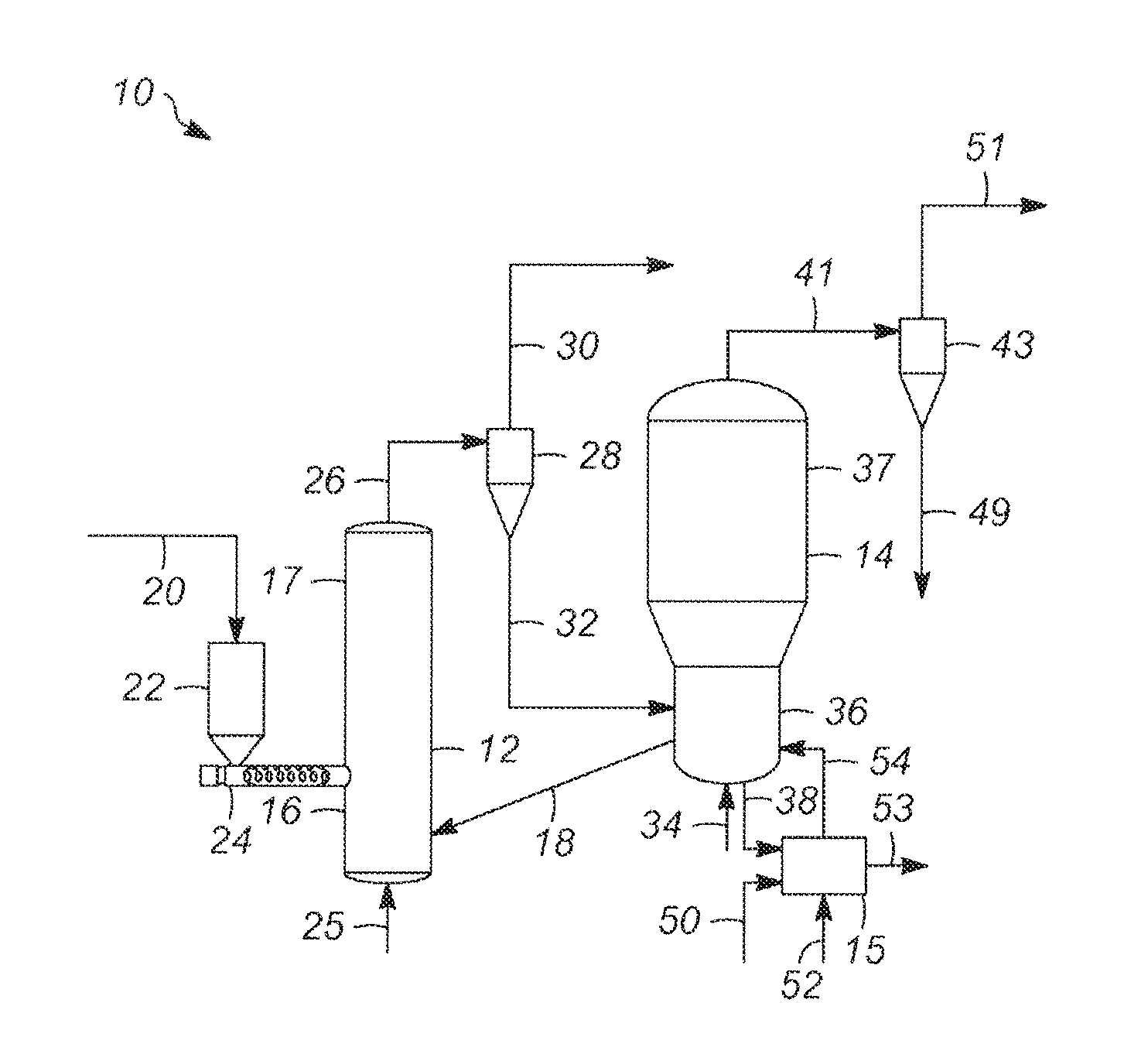
[0011] FIG. 1 schematically illustrates an apparatus for rapid thermal processing of carbonaceous material in accordance with an exemplary embodiment;
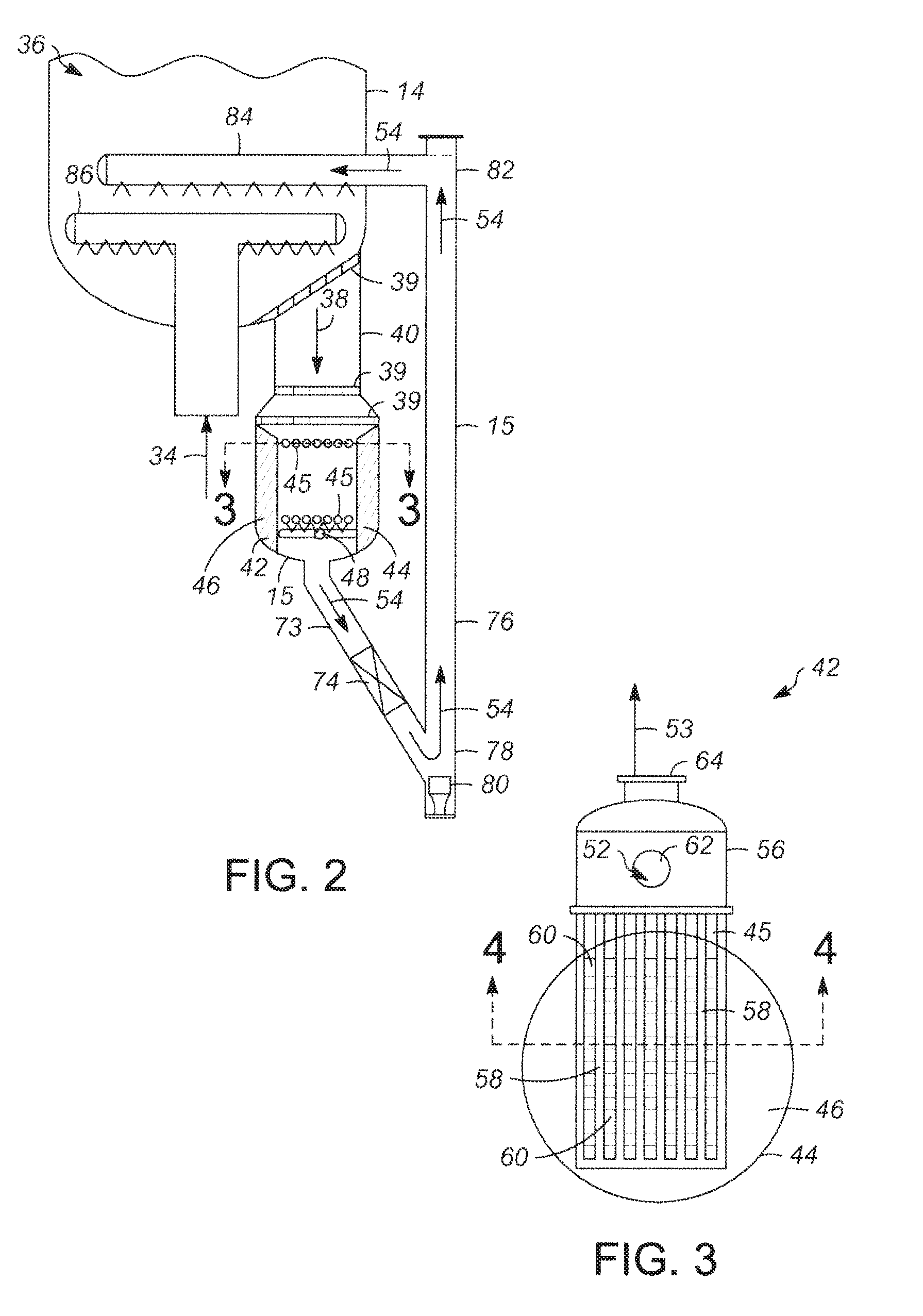
[0012] FIG. 2 is a partial sectional view of the apparatus depicted in FIG. 1 including an inorganic particle cooler in accordance with an exemplary embodiment;
[0013] FIG. 3 is a sectional view of the inorganic particle cooler depicted in FIG. 2 along line 3-3; and
[0014] FIG. 4 is a sectional view of the inorganic particle cooler depicted in FIG. 3 along line 4-4.
DETAILED DESCRIPTION
[0015] The following Detailed Description is merely exemplary in nature and is not intended to limit the invention or the application and uses of the invention. Furthermore, there is no intention to be bound by any theory presented in the preceding Background of the Invention or the following Detailed Description.
[0016] Various embodiments contemplated herein relate to apparatuses and methods for controlling heat for rapid thermal processing of carbonaceous material. Unlike the prior art, the exemplary embodiments taught herein provide an apparatus comprising a reactor, a reheater that is in fluid communication with the reactor, and an inorganic particle cooler that is in fluid communication with the reheater. The reactor rapidly pyrolyzes a carbonaceous feedstock with heated inorganic particles to form pyrolysis gases and solids that include cooled inorganic heat carrier particles and char. A cyclone separates the pyrolysis gases from the solids. The reheater receives the solids and fluidizes the cooled inorganic heat carrier particles and char with an oxygen-containing gas to form a fluidized bubbling bed. The reheater is operating at combustion conditions effective to burn the char into ash and reheat the cooled inorganic heat carrier particles to form heated inorganic particles.
[0017] The inorganic particle cooler comprises a shell portion and a tube portion that is disposed in the shell portion. In an exemplary embodiment, a portion of the heated inorganic particles is fluidly communicated to the shell portion of the inorganic particle cooler and a cooling medium is fluidly communicated to the tube portion. Some of the heat from the heated inorganic particles is indirectly exchanged with the cooling medium to partially cool the heated inorganic particles, forming a heated cooling medium and first partially-cooled heated inorganic particles. The heated cooling medium is removed from the inorganic particle cooler and can be used, for example, as part of the heat integration with the other equipment to optimize energy integration. If the cooling medium is water for instance, the water/steam production from the inorganic particle cooler can be returned to a steam drum to recover net steam for further facility usage. The first partially-cooled heated inorganic particles are fluidly communicated to the reheater and combined with the remaining portion of the heated inorganic particles to partially cool the heated inorganic particles, forming second partially-cooled heated inorganic particles. The second partially-cooled heated inorganic particles are fluidly communicated to the reactor for continued rapid pyrolysis of the carbonaceous feedstock. The inventors have found that partially cooling the heated inorganic particles with the inorganic particle cooler facilitates controlling the temperatures from excessively rising in the reheater even if the fluidized bubbling bed contains higher levels of char. Accordingly, the reheater does not require additional volume that would otherwise be needed to accommodate additional air for cooling to control the reheater temperatures and therefore, the cost and complexity of shipping, installing, and operating the reheater is not substantially impacted. The heated cooling medium can also be of further use to optimize the heat integration of the unit.
[0018] Referring to FIG. 1, a schematic depiction of an apparatus 10 for rapid thermal processing of a carbonaceous material in accordance with an exemplary embodiment is provided. The apparatus 10 comprises an upflow transport reactor 12, a reheater 14, and an inorganic particle cooler 15. The reactor 12 is configured for achieving a relatively high temperature within a minimum amount of time as well as providing a relatively short residence time at the high temperature to affect fast pyrolysis of a carbonaceous feedstock 20 (e.g. biomass including biomass waste). The relatively high temperature is achieved in a lower portion 16 of the reactor 12 using heated inorganic heat carrier particles 18 (e.g., heated sand) that are supplied from the reheater 14 to drive the pyrolysis process.
[0019] As illustrated, the carbonaceous feedstock 20 is supplied to a feed bin 22 where a reactor feed conveyor 24 introduces the carbonaceous feedstock 20 to the lower portion 16 of the reactor 12. Preferably, the carbonaceous feedstock 20 has been previously dried and has a moisture content of about 6 weight percent (wt. %) or less. A carrier gas 25, which can be a recirculation gas collected from a suitable location along the apparatus 10, is also introduced to the lower portion 16 of the reactor 12. The carrier gas 25 preferably contains less than about 1 wt. % of oxygen, and more preferably, less than about 0.5 wt. % of oxygen so that there is very little or no oxygen present thus minimizing or preventing oxidation and/or combustion of the carbonaceous feedstock 20 in the reactor 12.
[0020] Rapid mixing of the heated inorganic heat carrier particles 18 and the carbonaceous feedstock 20 occur in the lower portion 16 of the reactor 12. As the mixture advances up the reactor 12 in turbulent flow with the carrier gas 25, heat is transferred from the heated inorganic heat carrier particles 18 to the carbonaceous feedstock 20. In an exemplary embodiment, mixing and rapid heat transfer occurs within about 10% of the desired overall reactor resident time. Accordingly, the mixing time is preferably less than about 0.1 seconds, and more preferably within about 0.015 to about 0.030 seconds. In an exemplary embodiment, the temperature in the lower portion 16 of the reactor 12 is from about 600 to about 780.degree. C., and the heating rate of the carbonaceous feedstock 20 is preferably about 1000.degree. C. per second or greater. The use of sand or other suitable inorganic particulate as a solid heat carrier enhances the heat transfer because of the higher heat carrying capacity of the inorganic particles, and the ability of the inorganic particles to mechanically ablate the surface of the reacting carbonaceous material.
[0021] As the heated mixture is carried towards an upper portion 17 of the reactor 12 with the carrier gas 25, fast pyrolysis of the carbonaceous feedstock 20 occurs. In an exemplary embodiment, the temperature in the upper portion 17 of the reactor 12 is from about 450 to about 600.degree. C. The sand or other inorganic heat carrier particles and the carrier gas 25, along with the product vapors 30 and char form a product stream 26 that is carried out of the upper portion 17 of the reactor 12 to a cyclone 28. The cyclone 28, preferably a reverse flow cyclone, removes the solids 32, e.g., sand and char, from the product vapors 30, which comprise the carrier gas 25, non-condensible product gases and the primary condensible vapor products. The product vapors 30 are removed from the cyclone 28 and passed to a Quench Tower (not shown), for example, for rapid cooling or quenching to preserve the yields of the valuable non-equilibrium products in the product vapors 30. The solids 32 are removed from the cyclone 28 and passed to the reheater 14.
[0022] The reheater 14 receives an oxygen-containing gas 34, which is typically air. The solids 32 are contained in a lower portion 36 of the reheater 14 and are fluidized by the oxygen-containing gas 34 from a gas distributor 86 (see FIG. 2) to form a fluidized bubbling bed of char, inorganic heat carrier particles, and the oxygen-containing gas 34. The reheater 14 is operating at combustion conditions to burn the char into ash and flue gas. The energy released from combustion of the char reheats the inorganic heat carrier particles to form heated inorganic particles. In an exemplary embodiment, the heated inorganic particles have a temperature of from about 600 to about 780.degree. C.
[0023] The flue gas, entrained sand, and ash rise to the upper portion 37 of the reheater 14 and are carried out of the reheater 14 as an exhaust stream 41 to a cyclone 43. The cyclone 43, preferably a reverse flow cyclone, removes the sand and ash from the flue gas. The flue gas is passed along as a gas stream 51 for exhausting, subsequent processing, recirculation, or a combination thereof, and the sand and ash are passed along as a solids-containing stream 49 for disposal or subsequent processing.
[0024] Referring also to FIG. 2, in an exemplary embodiment, a portion of heated inorganic particles 38 is removed from the reheater 14 and introduced to the inorganic particle cooler 15. As illustrated, the portion of heated inorganic particles 38 is removed from the lower portion 36 of the reheater 14 and passed along a cooler inlet pipe 40 through a plurality of bubble breaking gratings 39 to an exchanger vessel 42. The bubble breaking gratings 39 break up any larger air-bubbles, for example, from the fluidized inorganic particles that otherwise may be passed along countercurrent to the portion of heated inorganic particles 38, back up to the bubbling bed at the lower portion 36 of the reheater 14. Big bubbles in the fluidized bed affect the reheater's 14 performance and solid entrainment. The bubble breaking gratings 39 also serve as a screener to prevent bigger chunks of materials, such as refractory from directly blocking or damaging the tube portion 45 and reducing the inorganic particle cooler capacity.
[0025] In an exemplary embodiment, the exchanger vessel 42 is configured as a heat exchanger and comprises a shell portion 44 and a tube portion 45 that is disposed in the shell portion 44. Disposed on an inner surface of the shell portion 44 is a refractory lining 46 that directs the portion of heated inorganic particles 38 through the shell portion 44 and into contact with the tube portion 45. The refractory lining 46 is preferably made of an abrasion-resistant/insulation material to protect the shell portion 44 from being damaged or overheating from the continuous flow of the abrasive heated inorganic particles. Downstream from the tube portion 45 is an air distributor 48 that receives an airstream 50 (shown in FIG. 1) and distributes the airstream 50 into the exchanger vessel 42 to help fluidized and advance the portion of heated inorganic particles 38 through the exchanger vessel 42.
[0026] The tube portion 45 of the exchanger vessel 42 receives a cooling medium 52 (shown in FIGS. 1 and 3) for indirect heat exchange with the portion of heated inorganic particles 38 to form partially-cooled heated inorganic particles 54 and a heated cooling medium 53. In an exemplary embodiment, the partially-cooled heated inorganic particles 54 have a temperature of from about 500 to about 680.degree. C. Preferably, the cooling medium 52 is water and the heated cooling medium 53 comprises water/steam that may be used elsewhere within the facility. Alternatively, the cooling medium 52 may be thermal oil or any other thermally conductive fluid known to those skilled in the art.
[0027] Referring to FIGS. 3 and 4, in an exemplary embodiment, the exchanger vessel 42 further comprises an exchanger head 56 that is in fluid communication with the tube portion 45. As illustrated, a plurality of tubes 58 are juxtaposed and extend outwardly from the exchanger head 56 substantially along a horizontal plane. Each of the tubes 58 has an outer surface with one or more cooling fins 60 that can extend, for example, radially or longitudinally outward from the outer surface. The cooling fins 60 facilitate indirect heat exchange between the portion of the heated inorganic particles 38 advancing through the shell portion 44 and the cooling medium 52 advancing through the tube portion 45.
[0028] The exchanger head 56 has an inlet 62 for receiving the cooling medium 52 and an outlet 64 for removing the heated cooling medium 53 from the exchanger vessel 42. Each of the plurality of tubes 58 has an inner tube section 66 and an outer tube section 68 that is disposed around the inner tube section 66. An outer channel 70 is formed between the inner and outer tube sections 66 and 68 and an inner channel 72 is formed in the inner tube section 66. The exchanger head 56 and tube portion 45 are configured such that the cooling medium 52 is advanced through the outer channel 70 for indirect heating with the portion of heated inorganic particles 38, forming the partially-cooled heated inorganic particles 54 and the heated cooling medium 53. The heated cooling medium 53 is advanced through the inner channel 72 countercurrent to the cooling medium 52 and removed from the exchanger head 56 through the outlet 64.
[0029] As illustrated in FIG. 2, the partially-cooled heated inorganic particles 54 are removed from the exchanger vessel 42 and passed along a cooler standpipe 73. The cooler standpipe 73 has an expansion joint-slide valve 74 for controlling the flow rate of the partially-cooled heated inorganic particles 54. A lift riser 76 is downstream from the exchanger vessel 42 and is fluidly coupled to the cooler standpipe 73 for receiving the partially-cooled heated inorganic particles 54. Disposed in a lower portion 78 of the lift riser 76 is an air nozzle 80 that is configured to direct the partially-cooled heated inorganic particles 54 through the lift riser 76 to an upper portion 82 of the lift riser 76.
[0030] A sand-air distributor 84 is disposed in the reheater 14 above the gas distributor 86 and is fluidly coupled to the lift-riser 76 to receive the partially-cooled heated inorganic particles 54. The sand-air distributor 84 is configured to distribute the partially-cooled heated inorganic particles 54 in the reheater 14, preferably above the gas distributor 86, to partially cool the remaining portion of the heated inorganic particles and form the heated inorganic heat carrier particles 18. Referring also to FIG. 1, in exemplary embodiment, the heated inorganic heat carrier particles 18 have a temperature of from about 600 to about 780.degree. C. and are passed along to the reactor 12 for rapidly pyrolyzing additional carbonaceous material.
[0031] Accordingly, apparatuses and methods for controlling heat for rapid thermal processing of carbonaceous material have been described. Unlike the prior art, the exemplary embodiments taught herein provide an apparatus comprising a reactor, a reheater, and an inorganic particle cooler. The reactor rapidly pyrolyzes a carbonaceous feedstock with heated inorganic particles to form pyrolysis oil and solids that include cooled inorganic heat carrier particles and char. The reheater receives the solids and fluidizes the cooled inorganic heat carrier particles and char with an oxygen-containing gas to form a fluidized bubbling bed. The reheater is operating at combustion conditions effective to burn the char into ash and heat the cooled inorganic heat carrier particles to form heated inorganic particles. The inorganic particle cooler receives a portion of the heated inorganic particles and removes some of the heat via indirect exchange to form partially-cooled heated inorganic particles that are combined with the remaining portion of the heated inorganic particles to partially cool the heated inorganic particles. It has been found that partially cooling the heated inorganic particles with the inorganic particle cooler facilitates controlling the temperatures from excessively rising in the reheater even if the fluidized bubbling bed contains higher levels of char. Accordingly, the reheater does not require additional volume that would otherwise be needed to accommodate additional air for cooling to control the reheater temperatures and therefore, the cost and complexity of shipping, installing, and operating the reheater is not substantially impacted.
[0032] While at least one exemplary embodiment has been presented in the foregoing Detailed Description, it should be appreciated that a vast number of variations exist. It should also be appreciated that the exemplary embodiment or exemplary embodiments are only examples, and are not intended to limit the scope, applicability, or configuration of the invention in any way. Rather, the foregoing Detailed Description will provide those skilled in the art with a convenient road map for implementing an exemplary embodiment of the invention, it being understood that various changes may be made in the function and arrangement of elements described in an exemplary embodiment without departing from the scope of the invention as set forth in the appended Claims and their legal equivalents.
* * * * *
D00000
D00001
D00002
D00003
XML
uspto.report is an independent third-party trademark research tool that is not affiliated, endorsed, or sponsored by the United States Patent and Trademark Office (USPTO) or any other governmental organization. The information provided by uspto.report is based on publicly available data at the time of writing and is intended for informational purposes only.
While we strive to provide accurate and up-to-date information, we do not guarantee the accuracy, completeness, reliability, or suitability of the information displayed on this site. The use of this site is at your own risk. Any reliance you place on such information is therefore strictly at your own risk.
All official trademark data, including owner information, should be verified by visiting the official USPTO website at www.uspto.gov. This site is not intended to replace professional legal advice and should not be used as a substitute for consulting with a legal professional who is knowledgeable about trademark law.