Coolant Reservoir Tank
Mark; Dennis Matthew ; et al.
U.S. patent application number 16/210861 was filed with the patent office on 2019-06-06 for coolant reservoir tank. The applicant listed for this patent is ILLINOIS TOOL WORKS INC.. Invention is credited to Serge Iafrate, Joseph Kuhn, Dennis Matthew Mark, Louis Sigioltzakis.
| Application Number | 20190170053 16/210861 |
| Document ID | / |
| Family ID | 66658942 |
| Filed Date | 2019-06-06 |


View All Diagrams
| United States Patent Application | 20190170053 |
| Kind Code | A1 |
| Mark; Dennis Matthew ; et al. | June 6, 2019 |
Coolant Reservoir Tank
Abstract
A coolant reservoir tank includes a first compartment that is configured to receive and retain a first portion of a liquid coolant. The first compartment is configured to be in fluid communication with a first liquid cooling circuit. A second compartment is configured to receive and retain a second portion of the liquid coolant. The second compartment is configured to be in fluid communication with a second liquid cooling circuit. A dividing wall separates the first compartment from the second compartment. The coolant reservoir tank further includes a fill port.
| Inventors: | Mark; Dennis Matthew; (Buffalo Grove, IL) ; Kuhn; Joseph; (Des Plaines, IL) ; Sigioltzakis; Louis; (Des Plaines, IL) ; Iafrate; Serge; (Montmerle sur Saone, FR) | ||||||||||
| Applicant: |
|
||||||||||
|---|---|---|---|---|---|---|---|---|---|---|---|
| Family ID: | 66658942 | ||||||||||
| Appl. No.: | 16/210861 | ||||||||||
| Filed: | December 5, 2018 |
Related U.S. Patent Documents
| Application Number | Filing Date | Patent Number | ||
|---|---|---|---|---|
| 62594570 | Dec 5, 2017 | |||
| 62599898 | Dec 18, 2017 | |||
| Current U.S. Class: | 1/1 |
| Current CPC Class: | F01P 2050/24 20130101; F01P 11/029 20130101; F01P 2050/30 20130101; F01P 7/165 20130101 |
| International Class: | F01P 11/02 20060101 F01P011/02; F01P 7/16 20060101 F01P007/16 |
Claims
1. A coolant reservoir tank, comprising: a fill port; a first compartment configured to receive and retain a first portion of a liquid coolant received through the fill port, wherein the first compartment is configured to be in fluid communication with a first liquid cooling circuit; a second compartment configured to receive and retain a second portion of the liquid coolant received through the fill port, wherein the second compartment is configured to be in fluid communication with a second liquid cooling circuit; and a dividing wall separating the first compartment from the second compartment.
2. The coolant reservoir tank of claim 1, further comprising a fill port including a passage in fluid communication with the first compartment and second compartment.
3. The coolant reservoir tank of claim 1, further comprising a receiving chamber in fluid communication with a fill channel, wherein the fill channel fluidly connects to both the first compartment and the second compartment.
4. The coolant reservoir tank of claim 3, wherein the receiving chamber includes a fill bay with a lower ledge disposed at a maximum design fluid level of the coolant reservoir tank.
5. The coolant reservoir tank of claim 1, wherein the dividing wall is insulated to reduce heat transfer between the first portion and the second portion of the liquid coolant.
6. The coolant reservoir tank of claim 1, further comprising a fluid-separating rib disposed underneath the fill port.
7. The coolant reservoir tank of claim 6, wherein the fluid-separating rib is integral with a cover.
8. The coolant reservoir tank of claim 6, wherein the fluid-separating rib includes a recess disposed therein to create a gap between the dividing wall and the fluid separating rib.
9. The coolant reservoir tank of claim 6, wherein the fluid-separating rib comprises: a central apex; a first receding side downwardly extending from the central apex; and a second receding side downwardly extending from the central apex.
10. The coolant reservoir tank of claim 1, further comprising a sump, wherein the sump comprises an internal barrier wall, and one or more openings that fluidly connect the sump to the first compartment and the second compartment.
11. The coolant reservoir tank of claim 1, wherein the dividing wall comprises an opening formed at a lower portion.
12. The coolant reservoir tank of claim 11, wherein a channeling wall defines a fluid passage that is in fluid communication with the opening.
13. The coolant reservoir tank of claim 1 further including a separating port positioned between the fill port and the dividing wall.
14. The coolant reservoir tank of claim 13, wherein the separating port is selectively configurable to be in fluid communication with either the first compartment, the second compartment, or both the first and second compartments.
15. A coolant reservoir tank, comprising: a first compartment configured to receive and retain a first portion of a liquid coolant, wherein the first compartment is configured to be in fluid communication with a first liquid cooling circuit; a second compartment configured to receive and retain a second portion of the liquid coolant, wherein the second compartment is configured to be in fluid communication with a second liquid cooling circuit; a dividing wall separating the first compartment from the second compartment, which includes an opening formed at a lower portion thereof; a fill port; and a separating port positioned between the fill port and the dividing wall, which includes a first fluid opening to the first compartment and a second fluid opening to the second compartment.
16. The coolant reservoir tank of claim 15, wherein the separating port is selectively configurable to be in fluid communication with either the first compartment, the second compartment, or both the first and second compartments.
17. The coolant reservoir of claim 15 further including a channeling wall defining a fluid passage that is in fluid communication with the opening of the dividing wall.
18. The coolant reservoir of claim 15, wherein a fluid-separating rib is provided underneath the fill port.
19. The coolant reservoir tank of claim 15 further including a sump, wherein the sump comprises an internal barrier wall and one or more openings that fluidly connect the sump to the first compartment and the second compartment.
20. A liquid cooling circuit system for a vehicle, the system comprising: a first circuit comprising one or more components, wherein one of the components is a battery; a second circuit comprising one or more components, wherein one of the components is an inverter system circuit; and a coolant reservoir tank for retaining and circulating liquid coolant in relation to the first circuit and the second circuit, the coolant reservoir tank comprising: a first compartment that is configured to receive and retain a first portion of a liquid coolant, wherein the first compartment is configured to be in fluid communication with the battery, a second compartment that is configured to receive and retain a second portion of the liquid coolant, wherein the second compartment is configured to be in fluid communication with the inverter system circuit, a dividing wall that separates the first compartment from the second compartment, and a fill port in fluid communication with the first compartment and the second compartment.
Description
RELATED APPLICATION
[0001] The present application claims the benefit of U.S. Provisional Application No. 62/594,570, filed on Dec. 5, 2017, and U.S. Provisional Application No. 62/599,898, filed on Dec. 18, 2017, both of which are incorporated herein by reference in their entirety.
BACKGROUND
Field of the Disclosure
[0002] Embodiments of the present disclosure generally relate to a coolant reservoir tank for a vehicle and, more particularly, to a coolant reservoir tank that is configured to provide liquid coolant to multiple components through multiple cooling circuits.
Description of the Background of Disclosure
[0003] Various motor vehicles, such as automobiles, trucks, buses, and the like, include components that generate heat during operation. A typical vehicle with an internal combustion engine (ICE) includes a cooling system that is configured to circulate liquid coolant through these components, e.g., a battery, an engine block, an inverter system circuit (ISC), and the like, to absorb the heat. The heat is carried through the liquid coolant and exchanged through another component, such as a radiator.
[0004] In one example, a vehicle with an ICE may include a single cooling circuit through which liquid coolant is circulated to cool multiple components. This single cooling circuit includes a single coolant reservoir tank retaining liquid coolant at a particular operating temperature.
[0005] However, other vehicles may employ multiple cooling circuits for more complex or higher capacity cooling systems, such as hybrid vehicles. In one example, a vehicle may have multiple separate and distinct cooling circuits operating at different temperatures to serve one or more distinct components. There, a first cooling circuit includes a first coolant reservoir tank that retains liquid coolant at a particular operating temperature that is delivered to and received from one or more components. Then, a second cooling circuit includes a second coolant reservoir tank that retains liquid coolant at another particular operating temperature that is delivered to and received from another one or more components. In this manner, each cooling circuit requires a single cooling reservoir tank for retaining the liquid coolant at a particular operating temperature. Accordingly, these vehicles may have two or more coolant reservoir tanks, each retaining liquid coolant at different operating temperatures.
[0006] However, space within a vehicle is limited. As can be appreciated, each coolant reservoir tank within a vehicle occupies space therein, which renders the space unavailable for other components. A need therefore exists for a compact coolant reservoir tank that may be disposed within a vehicle. Further, a need exists for a coolant reservoir tank that retains liquid coolant at different operating temperatures that is circulated through multiple cooling circuits to cool one or more components.
SUMMARY
[0007] In one aspect, a coolant reservoir tank comprises a first compartment that is configured to receive and retain a first portion of a liquid coolant. The first compartment is configured to be in fluid communication with a first cooling circuit. A second compartment is configured to receive and retain a second portion of the liquid coolant. The second compartment is configured to be in fluid communication with a second cooling circuit. A dividing wall separates the first compartment from the second compartment.
[0008] Further, the coolant reservoir tank includes a fill port.
[0009] In one embodiment, the dividing wall may be insulated to reduce heat transfer between the first portion and the second portion of the liquid coolant. The dividing wall may connect to a base and a cover of the coolant reservoir tank.
[0010] In another embodiment, the coolant reservoir tank also includes a fill port including a passage in fluid communication with the first compartment and the second compartment. The fill port is used to fill both the first compartment and the second compartment with the respective first portion and the second portion of the liquid coolant.
[0011] In at least one embodiment, the coolant reservoir tank includes a receiving chamber that connects to, or is otherwise in fluid communication with, a fill channel that fluidly connects to both the first compartment and the second compartment. The receiving chamber includes a fill bay with a lower ledge disposed at a maximum design fluid level of the coolant reservoir tank.
[0012] In a different embodiment, a fluid-separating rib is positioned underneath a fill port. The fluid-separating rib may be part of a cover of the coolant reservoir tank. The fluid-separating rib may be supported by the dividing wall. In some embodiments, the fluid-separating rib may be spaced apart from the dividing wall. The fluid-separating rib may include a central apex, a first receding side downwardly extending from the central apex, and a second receding side downwardly extending from the central apex.
[0013] In a further embodiment, a separating port is positioned between a fill port and the dividing wall. The separating port may include a first fluid opening fluidly connected to the first compartment, and a second fluid opening fluidly connected to the second compartment. The separating port may be selectively configurable to be in fluid communication with either the first compartment, the second compartment, or both the first and second compartments
[0014] In still another embodiment, the dividing wall includes an opening formed at a lower portion. A channeling wall may be within one of the first compartment or the second compartment. The channeling wall may define a fluid passage that is in fluid communication with the opening.
[0015] In yet another embodiment, the coolant reservoir tank also includes a sump. The sump may include an internal barrier wall. One or more openings may fluidly connect the sump to the first compartment and the second compartment.
[0016] In another aspect, a coolant reservoir tank comprises a first compartment that is configured to receive and retain a first portion of a liquid coolant. The first compartment is configured to be in fluid communication with a first component. A second compartment is configured to receive and retain a second portion of the liquid coolant. The second compartment is configured to be in fluid communication with a second component. A dividing wall separates the first compartment from the second compartment, which includes an opening formed at a lower portion thereof. Further, a fill port is provided. Still further, a separating port is positioned between the fill port and the dividing wall, which includes a first fluid opening to the first compartment and a second fluid opening to the second compartment.
[0017] In still another aspect, a liquid cooling circuit system for a vehicle comprises a first circuit having one or more components, wherein one of the components is a battery. The liquid cooling system also includes a second circuit having one or more components, wherein one of the components is an inverter system circuit. A coolant reservoir tank for retaining and circulating liquid coolant in relation to the first circuit and the second circuit is provided, which comprises a first compartment, a second compartment, a dividing wall, and a fill port. The first compartment is configured to receive and retain a first portion of a liquid coolant, wherein the first compartment is configured to be in fluid communication with the battery. The second compartment is configured to receive and retain a second portion of the liquid coolant, wherein the second compartment is configured to be in fluid communication with the inverter system circuit. The dividing wall separates the first compartment from the second compartment and the fill port is in fluid communication with the first compartment and the second compartment.
DESCRIPTION OF THE DRAWINGS
[0018] FIG. 1 is a perspective view of a front, top, and left side of a coolant reservoir tank, with portions shown in transparency for purposes of clarity to show internal portions thereof;
[0019] FIG. 2 is a cross-sectional view of a portion of the coolant reservoir tank of FIG. 1 taken along line 2-2 of FIG. 1;
[0020] FIG. 3 is a cross-sectional view of the coolant reservoir tank of FIG. 1 taken along line 3-3 of FIG. 1;
[0021] FIG. 4 is a fragmentary view of a top, side, and internal side of a fill port of a coolant reservoir tank;
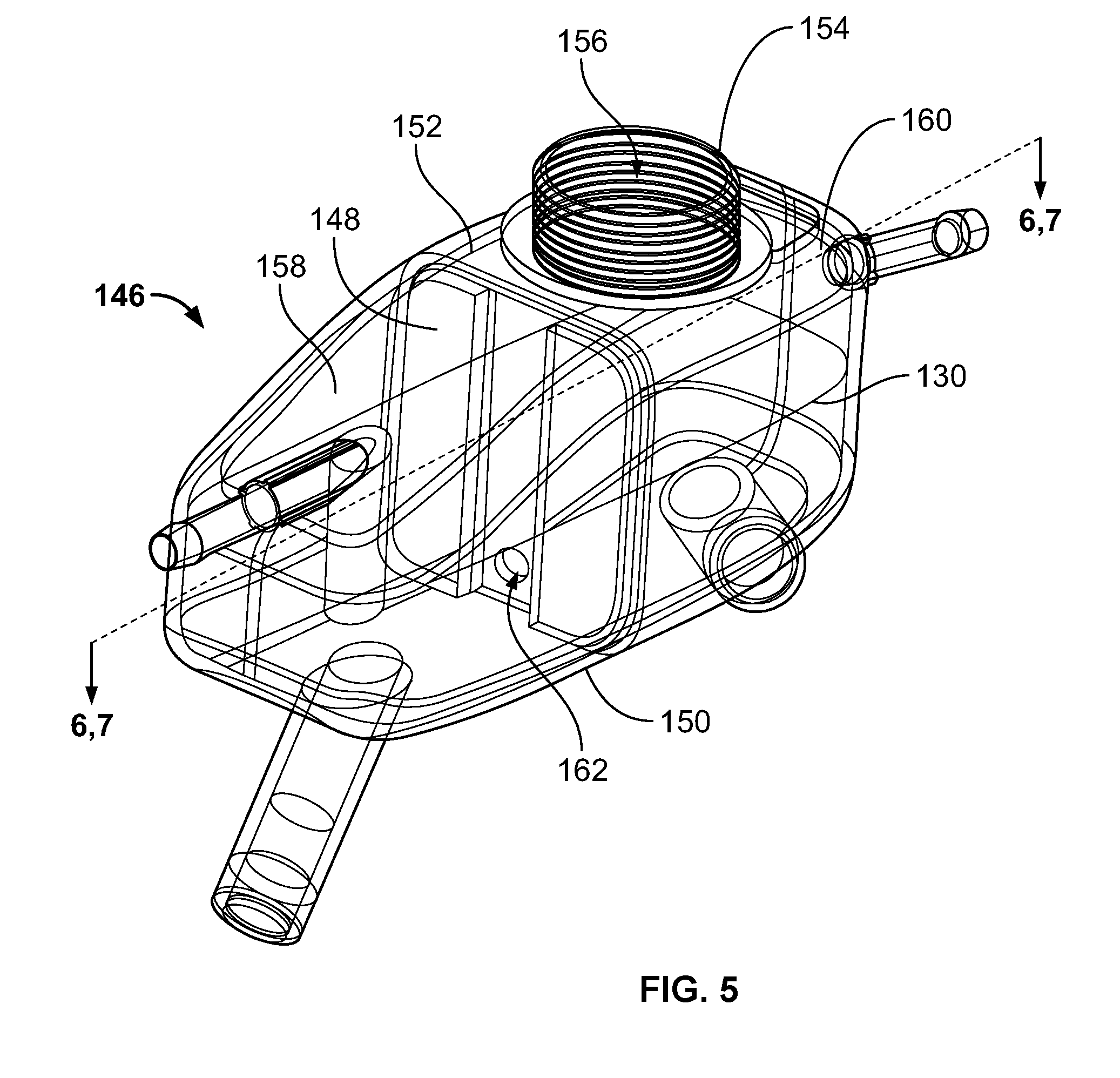
[0022] FIG. 5 is a perspective view of a front, top, and left side of another embodiment of a coolant reservoir, wherein portions are shown in transparency to show internal portions thereof;
[0023] FIG. 6 is a top plan view of the coolant reservoir tank of FIG. 5, showing a fragmentary sectional view taken along the line 6-6 of FIG. 5;
[0024] FIG. 7 is a perspective view of a top and left side of a portion of a dividing wall of the coolant reservoir tank of FIG. 6;
[0025] FIG. 8 is a perspective view of a front, top, and left side of yet another embodiment of a coolant reservoir tank;
[0026] FIG. 9 illustrates a perspective view of a front, top, and right side of the coolant reservoir tank of FIG. 8, further showing internal portions thereof;
[0027] FIG. 10 illustrates a top plan view of the base portion of the coolant reservoir tank of FIG. 8;
[0028] FIG. 11 is a perspective view of a top, front, and left side of another embodiment of a coolant reservoir tank, with portions shown in transparency to show internal portions thereof;
[0029] FIG. 12 is a perspective view of a front, top and left side of a cover of the coolant reservoir tank of FIG. 11;
[0030] FIG. 13 is a perspective view of a rear, bottom, and right side of the cover of FIG. 11;
[0031] FIG. 14 is a partial cross-sectional view of the coolant reservoir tank of FIG. 11 taken along the line 14-14 of FIG. 11;
[0032] FIG. 15 is top plan view of a lower section of still another embodiment of a coolant reservoir tank;
[0033] FIG. 16 is a perspective view of a portion of the lower section of the coolant reservoir tank of FIG. 15;
[0034] FIG. 17 is a perspective view of a bottom and rear of the coolant reservoir tank of FIG. 15; and
[0035] FIG. 18 is a schematic representation of a coolant reservoir tank having two internal compartments fluidly connected to liquid cooling circuits.
DETAILED DESCRIPTION
[0036] Embodiments of the present disclosure provide a coolant reservoir tank that includes multiple compartments that retain liquid coolant therein. The coolant reservoir tank may include a single fill point that is used to fill the compartments. Each compartment is in fluid communication with a separate and distinct cooling circuit that couples to one or more components. As such, isolated compartments within the coolant reservoir tank are provided within a single coolant reservoir tank that is in fluid communication with multiple cooling circuits. The compartments may be thermally insulated, such that heat transfer between fluids in the compartments is minimized or otherwise reduced.
[0037] FIG. 1 illustrates a coolant reservoir tank 100, according to one embodiment of the present disclosure. The coolant reservoir tank 100 is configured to be disposed within an engine bay of a vehicle (not shown). The coolant reservoir tank 100 provides a housing that includes a base 102 connected to a top wall or cover 104 through upstanding walls 106. The base 102, the cover 104, and the upstanding walls 106 may be formed of a plastic, for example. In at least one embodiment, the base 102, the cover 104, and the walls 106 are integrally molded and formed as a single housing. In a different embodiment, the cover 104 may be separately formed and secured over and onto the walls 106, such as through welding, adhesives, fasteners, and/or the like.
[0038] With continued reference to FIG. 1, a first inlet line 108 and a first outlet line 110 are in fluid communication with a first compartment 112 and a first circuit including one or more components. Similarly, a second inlet line 114 and a second outlet line 116 are in fluid communication with a second compartment 118 and a second circuit including one or more components. A fill port 120 extends into the cover 104. The fill port 120 includes a tubular fitting 122 that defines a central passage 124. An outer surface 126 of the fitting 122 includes threads 128 that are configured to be threadably retained to corresponding threads on an inner surface of a cap (not shown), which is configured to removably connect to the fitting 122. In order to fill the coolant reservoir tank 100, liquid coolant 130 is poured through the central passage 124 of the fill port 120. It is contemplated that in some embodiments, only a single fill port is provided that is in fluid communication with two or more compartments of a coolant reservoir tank.
[0039] The first compartment 112 is part of a first liquid circuit or loop that connects to one or more components, such as an ISC, while the second compartment 118 is part of a second liquid circuit or loop that connects to another one or more components, such as a battery. It should be stated that the ISC and the battery are merely examples of components within a vehicle coupled to a cooling circuit serving one or more such components. In fact, it is intended that the present disclosure be used with any components in, or otherwise in functional communication with, cooling circuits within a vehicle or other device. In one specific implementation, the first compartment 112 is fluidly connected to a first inlet line and a first outlet line (e.g., 108, 110) that fluidly connect to the first liquid circuit, and the second compartment 118 is fluidly connected to a second inlet line and a second outlet line (e.g., 114, 116) that fluidly connect to the second liquid circuit.
[0040] Now referring to FIGS. 2 and 3, an internal retaining chamber 131 is defined between the base 102, the cover 104, and the walls 106. The internal retaining chamber 131 is separated into the first compartment 112 (such as a first fluid retaining cell, chamber, volume, and/or the like) and the second compartment 118 (such as a second fluid retaining cell, chamber, volume, and/or the like). The first compartment 112 is separated from the second compartment 118 by a dividing wall 132, which prevents the liquid coolant 130 from comingling. In this manner, the first compartment 112 and the second compartment 118 may be filled simultaneously from the single fill port 120. Further, each of the cooling circuits remains separate and distinct from each other.
[0041] In some aspects, the dividing wall 132 may be thermally insulated to minimize heat transfer between or among the first and second compartments 112, 118. In the present embodiment, the first compartment 112 and the second compartment 118 are of equal volume. The first compartment 112 and the second compartment 118 may define different volumes in other embodiments.
[0042] With continued reference to FIGS. 2 and 3, the fill port 120 connects to a separating port 134 positioned between the fill port 120 and the dividing wall 132. The fill port 120 and the separating port 134 may be located over any portion of the dividing wall 132. In at least one alternative embodiment, the dividing wall 132 may extend an entire height of the internal chamber 131, to fully separate the compartments 112, 118. The separating port 134 includes wall(s) 136 enclosing a space that in the present embodiment is cylindrical or tubular. The tubular wall 136 connects to a lower ledge 138 that is positioned over the dividing wall 132. A fluid passage 140 is defined between the tubular wall 136 and the ledge 138. The fluid passage 140 fluidly connects to the central passage 124 of the fill port 120. The ledge 138 may be located at a height that coincides with a maximum fluid level within the coolant reservoir tank 100, which minimizes or otherwise reduces fluid communication between the first and second compartments 112, 118, and provides for an easier filling method.
[0043] A first fluid opening 142 is formed on one side of the separating port 134, while a second fluid opening 144 is formed on an opposite side of the separating port 134. The first fluid opening 142 fluidly connects to the first compartment 112, while the second fluid opening 144 fluidly connects to the second compartment 118. As such, liquid coolant 130 that passes into the fluid passage 140 of the separating port 134 passes into the first and second compartments 112, 118 via the first fluid opening 142 and the second fluid opening 144, respectively. As such, the liquid coolant 130 may be characterized as having a first portion in the first compartment 112 and a second portion in the second compartment 118. In this manner, both the first compartment 112 and second compartment 118 may be filled with liquid coolant 130 simultaneously through the fill port 120.
[0044] Additionally or alternatively, the separating port 134 may further include a tubular sleeve (not shown) that is concentrically positioned within the tubular wall 136 and includes a single fluid opening having similar dimensions as the first or second fluid opening, 142, 144. The tubular sleeve may be selectively rotated by a user to align the single fluid opening with either the first or second fluid opening 142, 144, thereby allowing a user to fill either the first compartment 112 or the second compartment 118 individually. The tubular sleeve may be configured to be removable, or to have a projection, similar to a handle, capable of facilitating manipulation by a user. As such, the tubular sleeve may permit a user to fill the first chamber 112 before the second chamber 118, or to fill the first chamber 112 with a particular type of liquid coolant 130 and the second chamber 118 with a different variant of liquid coolant 130.
[0045] It is also contemplated that the tubular sleeve of the present embodiment could include two or more fluid openings that may be aligned with a corresponding number of openings in a separating port. For example, if a separating port included two openings in communication with different compartments, the tubular sleeve may be rotatable into fluid alignment with only one of the openings in the separating port, none of the openings in the separating port, or both of the openings in the separating port.
[0046] Now referring to FIG. 4, the separating port 134 can be seen extending below the central passage 124 of the fill port 120. The second fluid opening 144 is formed in the tubular wall 136 above the lower ledge 138 and beneath the central passage 124.
[0047] Referring to FIG. 5, according to another embodiment of a coolant reservoir tank 146, a dividing wall 148 may extend from an upper surface of a base 150 to a lower surface of a top wall or cover 152. The cover 152 includes a fill port 154 having a downwardly extending central passage 156, which is in fluid communication with a first compartment 158 and a second compartment 160. An opening 162 may be formed through a lower portion of the dividing wall 148. As shown in FIGS. 6 and 7, the opening 162 fluidly connects to a fluid passage 164 formed by a channeling wall 166 within the second compartment 160. The channeling wall 166 extends upwardly from the opening 162 toward the cover 152. The channeling wall 166 may angle downwardly from an open upper receiving end toward the opening 162. In this manner, the channeling wall 166 is configured to receive liquid coolant 130 within the fluid passage 164 and channel the liquid coolant 130 toward and into the opening 162.
[0048] It is contemplated that the channeling wall 166 may be located underneath or proximate to the fill port 154 (shown in FIGS. 5 and 6), which may be located above the second compartment 160. In other embodiments, the channeling wall 166 may be located within the first compartment 158, and the fill port 154 may be located above the first compartment 158.
[0049] In order to fill the first and second compartments 158, 160 with the liquid coolant 130, the liquid coolant 130 passes into the second compartment 160 through the fill port 154. The liquid coolant 130 may first fill the second compartment 160. As the liquid coolant 130 reaches the height of an upper edge of the channeling wall 166, a portion of the liquid coolant 130 spills into the fluid passage 164 and passes into the first compartment 158 via the opening 162, until both the first and second compartments 158, 160 are filled to a desired level. In some embodiments, if the channeling wall 166 is positioned directly underneath the fill port 154, the first compartment 158 may be filled first, and liquid coolant 130 may then spill over the upper edge of the channeling wall 166 into the second compartment 160.
[0050] It is contemplated that the opening 162 may be sized and shaped differently than shown. In at least one embodiment, the channeling wall 166 may be angled in order to retain liquid coolant 130 thereon or therein.
[0051] With reference to FIGS. 8 and 9, another embodiment of a coolant reservoir tank 168 is depicted having a base 170, a top wall or cover 172, and walls 174. The cover 172 includes a fill port 176 having a central passage 178 extending below the inside surface of the cover 172.
[0052] As shown in FIG. 9, the central passage 178 connects to a receiving chamber 180 defined between an internal wall 182 and an upper surface of a lower ledge 184. A fill bay 186 is formed below the receiving chamber 180 and is defined by the internal wall 182 and the horizontal surface of the lower ledge 184 that is coplanar with a top of a dividing wall 188. The fill bay 186 connects to internal walls 190 that conform to a curvature of walls 174. The central passage 178 of the fill port 176 is in fluid communication with the receiving chamber 180 and the fill bay 186.
[0053] Still referring to FIG. 9, the lower ledge 184 of the fill bay 186 may be at a height of a maximum designed fluid level of the coolant reservoir tank 168. In this manner, a filling device (such as a filling gun) that is used to fill the coolant reservoir tank 168 may remove liquid so that the liquid coolant 130 within the coolant reservoir tank 168 is at an intended level as the filling device is drawn back from pressure filling.
[0054] With reference to FIG. 10, fluid passages 192 are formed in either side of the internal wall 182. The fluid passages 192 define portions of a fill channel 194 extending along the internal walls 190. The fill channel 194 includes a first outlet passage 196 and a second outlet passage 198. The first outlet passage 196 leads into a first compartment 200, while the second outlet passage 198 leads into a second compartment 202. Accordingly, after liquid coolant 130 is poured into the fill port 176 it then passes into the receiving chamber 180, over the lower ledge 184 of the fill bay 186, and into the fill channel 194 through both fluid passages 192. From there, the liquid coolant 130 then flows into both the first and second compartments 200, 202 through the first and second fluid outlet passages 196, 198, respectively. It is contemplated that the fill channel 194 may be inclined, angled, or otherwise disposed between the fill bay 186 and the first and second outlet passages 196, 198. For example, the fill channel 194 may decline from the fill bay 186 to the first and second outlet passages 196, 198 in order to promote efficient and consistent drainage (such as via gravity) of the liquid coolant 130 into the first and second compartments 200, 202.
[0055] Additionally, the fill port 176 and the fill bay 186 may be located proximate to a portion of the walls 174, and generally aligned with the dividing wall 188. In some embodiments, the fill port 176 and/or the fill bay 186 may be located at various other locations, such as at a center of the coolant reservoir tank 168, over one of the first or second compartments 200, 202, and/or the like.
[0056] In operation, the liquid coolant 130 within each of the first and second compartments 200, 202 is circulated in relation to first and second liquid circuits, having first and second inlet and outlet lines (not shown) extending therefrom. Liquid coolant 130 within the first compartment 200 is dedicated to the first liquid circuit, while liquid coolant 130 within the second compartment 202 is dedicated to the second liquid circuit. Accordingly, the single coolant reservoir tank 168 is used to supply liquid coolant 130 to two different cooling circuits in a parallel manner. Liquid coolant 130 within the separate first and second compartments 200, 202 is separated by the dividing wall 188 to prevent, limit, or otherwise reduce unintended comingling among the first and second compartments 200, 202. Further, the dividing wall 188, the outer wall 174, the base 170, and/or the cover 172 may be insulated to limit or otherwise reduce heat transfer between the first and second compartments 200, 202.
[0057] FIG. 11 illustrates another embodiment of a coolant reservoir tank 204. The coolant reservoir tank 204 includes first and second compartments 206, 208 separated by a fluid-separating rib 210. The first compartment 206 is in fluid communication with a first inlet line 212 and a first outlet line 214 that are also in fluid communication with a first liquid circuit. The second compartment 208 is in fluid communication with a second inlet line 216 and a second outlet line 218 that are in fluid communication with a second liquid circuit. The fluid-separating rib 210 is supported over a dividing wall 220. In at least one other embodiment, the fluid-separating rib 210 may be an upper portion of the dividing wall 220.
[0058] As depicted in FIGS. 11 and 12, a fill port 222 may be located over a central portion of a cover 224. A central passage 226 of the fill port 222 is provided directly over a central portion of the fluid-separating rib 210. In some embodiments, the fill port 222 may be located in other areas of the cover 224 either directly over the fluid-separating rib 210, or offset therefrom.
[0059] With reference to FIG. 12, the fluid-separating rib 210 is part of the cover 224. In other embodiments, the fluid-separating rib 210 may extend upwardly from a dividing wall that extends from an upper surface of a base 228 (see FIGS. 11 and 14). The fluid-separating rib 210 forms a splitting wall that allows liquid coolant 130 to drain downwardly over either side. In one embodiment, a recess 230 (shown in FIG. 13) may be disposed within the fluid separating rib 210 to form a gap between the fluid separating rib 210 and the dividing wall 220. Air may transfer through the gap between the first and second compartments 206, 208 to maintain a uniform air pressure within the coolant reservoir tank 204.
[0060] Referring now to FIGS. 12 and 14, the fluid-separating rib 210 may include a central apex 232 and receding sides 234, 236 that downwardly curve and/or angle from the apex 232. As such, liquid coolant 130 poured through the fill port 222 of the cover 224 drains downwardly over the sides 234, 236 and into the first and second compartments 206, 208, respectively. The apex 232 may extend into the central passage 226 of the fill port 222, thereby ensuring that liquid coolant 130 within the separate compartments 206, 208 does not comingle.
[0061] Referring to FIGS. 15-17, according to another embodiment the coolant reservoir tank 240 includes a sump 242. The sump 242 is positioned at a level below a predetermined normal level of liquid within the coolant reservoir tank 240. A barrier wall 244 (shown in FIGS. 15 and 16) may be disposed within the sump 240, which is positioned between a first compartment 246 and a second compartment 248. The barrier wall 244 is configured to slow liquid interchange between the two compartments 246 and 248. In some embodiments, the sump 242 may be positioned within one of the first or second compartments 246, 248, or otherwise offset from one of the compartments 246, 248.
[0062] As shown in FIGS. 15 and 16, openings 250 (such as holes) may be formed through an internal boundary wall 252 of the sump 242. The openings 250 fluidly connect an internal retaining chamber 251 of the sump 242 to the first and second compartments 246, 248. The openings 250 are configured to allow for fluid leveling such that the liquid coolant 130 may be retained at substantially the same volume in each of the first and second compartments 246, 248. The openings 250 may be various sizes and shapes to impact the rate of fluid leveling. In at least one embodiment, two or more openings 250 may fluidly connect the first and second compartments 246, 248 to the sump 242. An upper portion of the barrier wall 244 may be angled or otherwise inclined to further slow the rate of fluid exchange or limit the exchange in one or more liquid inclination states. Additionally, the sump 250 may be present within any of the coolant reservoir tank embodiments of FIGS. 1-18, including a coolant reservoir tank having a separating port, a channeling wall, or a fluid separating rib.
[0063] Now referring to FIGS. 1-17, the coolant reservoir tank embodiments include first and second compartments. In some embodiments, the coolant reservoir tanks may include additional compartments. For example, a coolant reservoir tank may include three separate compartments, or four separate compartments, or even five separate compartments separated by dividing walls. As such, a coolant reservoir tank may have more than one sump. Alternatively, a coolant reservoir may have a single sump in fluid communication with each of the two, or three, or four, or five compartments. Additionally, each compartment may be configured to receive particular types of liquid coolant 130 having different chemical properties, such as liquid coolants 130 suitable for use with higher temperatures or use in colder climates. In this manner, liquid coolant 130 may be retained at different temperatures inside the single coolant reservoir tank.
[0064] As will be appreciated from the schematic representation depicted in FIG. 18, a vehicle may have two distinct liquid cooling circuits coupled to a coolant reservoir tank 254. A first liquid cooling circuit includes a first compartment 256 disposed within the coolant reservoir tank 254 and fluidly connected with a first component 258 and a heat exchanger 260. The liquid coolant 130 retained in the first compartment 256 is circulated through the first component 258, absorbing the heat generated therefrom. The liquid coolant 130 carries the heat absorbed to the first heat exchanger 260 where it is transferred out of the first liquid cooling circuit.
[0065] Still with reference to FIG. 18, a second liquid cooling circuit includes a second compartment 262 disposed within the coolant reservoir tank 254 and fluidly connected with a second component 264, a third component 266, and a second heat exchanger 268. The liquid coolant 130 retained in the second compartment 262 is circulated through the second component 264, absorbing the heat generated therefrom. Then, liquid coolant 130 is circulated through the third component 266, absorbing the heat generated therefrom. Finally, the liquid coolant 130 carries the heat absorbed to the second heat exchanger 268 where it is transferred out of the second liquid cooling circuit. Optionally, the liquid coolant 130 may carry the heat absorbed from the second component 264 to the second heat exchanger, where such heat may be transferred out of the second liquid circuit prior to the liquid coolant being circulated to the third component 266. In this manner, the liquid coolant 130 may enter the third component 266 at a lower temperature. In some aspects, the first and second heat exchangers 260, 268 may be intertwined or split within a single high capacity heat exchanger 270.
[0066] While various spatial and directional terms, such as top, bottom, lower, mid, lateral, horizontal, vertical, front and the like may be used to describe embodiments of the present disclosure, it is understood that such terms are merely used with respect to the orientations shown in the drawings. The orientations may be inverted, rotated, or otherwise changed, such that an upper portion is a lower portion, and vice versa, horizontal becomes vertical, and the like.
[0067] Variations and modifications of the foregoing are within the scope of the present disclosure. It is understood that the embodiments disclosed and defined herein extend to all alternative combinations of two or more of the individual features mentioned or evident from the text and/or drawings. All of these different combinations constitute various alternative aspects of the present disclosure. The embodiments described herein explain the best modes known for practicing the disclosure and will enable others skilled in the art to utilize the disclosure. The claims are to be construed to include alternative embodiments to the extent permitted by the prior art.
* * * * *
D00000
D00001
D00002
D00003
D00004
D00005
D00006
D00007
D00008
D00009
D00010
D00011
D00012

D00013

XML
uspto.report is an independent third-party trademark research tool that is not affiliated, endorsed, or sponsored by the United States Patent and Trademark Office (USPTO) or any other governmental organization. The information provided by uspto.report is based on publicly available data at the time of writing and is intended for informational purposes only.
While we strive to provide accurate and up-to-date information, we do not guarantee the accuracy, completeness, reliability, or suitability of the information displayed on this site. The use of this site is at your own risk. Any reliance you place on such information is therefore strictly at your own risk.
All official trademark data, including owner information, should be verified by visiting the official USPTO website at www.uspto.gov. This site is not intended to replace professional legal advice and should not be used as a substitute for consulting with a legal professional who is knowledgeable about trademark law.