Heat Distribution Management Device For Wire Treatment
Massotte; Philippe
U.S. patent application number 16/207960 was filed with the patent office on 2019-06-06 for heat distribution management device for wire treatment. The applicant listed for this patent is Superba S.A.S.. Invention is credited to Philippe Massotte.
| Application Number | 20190169776 16/207960 |
| Document ID | / |
| Family ID | 60673107 |
| Filed Date | 2019-06-06 |

| United States Patent Application | 20190169776 |
| Kind Code | A1 |
| Massotte; Philippe | June 6, 2019 |
HEAT DISTRIBUTION MANAGEMENT DEVICE FOR WIRE TREATMENT
Abstract
The subject matter of this invention is a heat distribution management device in a treatment device of wires in movement on a means of transport, said means of transport being able to be traversed by a flow of heat at or through the of orifices, characterized in that the device comprises at least one means of sealing by coverage of at least one part of the orifices of the means of transport, said means of sealing being independent of the means of transport.
| Inventors: | Massotte; Philippe; (Gueberschwihr, FR) | ||||||||||
| Applicant: |
|
||||||||||
|---|---|---|---|---|---|---|---|---|---|---|---|
| Family ID: | 60673107 | ||||||||||
| Appl. No.: | 16/207960 | ||||||||||
| Filed: | December 3, 2018 |
| Current U.S. Class: | 1/1 |
| Current CPC Class: | D02J 13/001 20130101; C21D 9/525 20130101; B65H 51/20 20130101; B65H 2701/36 20130101; D06B 17/005 20130101; D06C 7/00 20130101 |
| International Class: | D06B 17/00 20060101 D06B017/00; C21D 9/52 20060101 C21D009/52 |
Foreign Application Data
| Date | Code | Application Number |
|---|---|---|
| Dec 4, 2017 | EP | 17205263.1 |
Claims
1. A heat distribution management device in a wire treatment device comprising: a transport device having orifices configured to be traversed by a flow of heat at the orifices; and at least one sealing device for covering at least one part of the orifices of the transport device, said sealing device being independent of the transport device.
2. The heat distribution management device of claim 1, wherein the sealing device is a fabric belt or a wire bundle.
3. The heat distribution management device of claim 1, wherein a length of the heat distribution management device is adapted to be at least equal to a length of the transport device.
4. The heat distribution management device of claim 1, wherein a length of the heat distribution management device is adapted to be at least equal to a length traveled by a wire in the wire treatment device.
5. The heat distribution management device of claim 1, wherein a width of the heat distribution management device corresponds to a width of all wires to be treated by the wire treatment device.
6. The heat distribution management device of claim 1, comprising at least one fastener on the sealing device configured to secure to one end of a wire or of one wire bundle.
7. A method for treating wires with a treatment device, comprising: a placement stage involving placement of a heat distribution management device on a transport device at an inlet opening of the treatment device; and a distribution stage involving distribution of the heat distribution management device on at least one part of a width of the transport device.
8. The method of claim 7, further comprising: a movement stage involving movement of the heat distribution management device on the transport device and a subsequently driving a least one wire to be treated; and an occupation stage involving occupation by the heat distribution management device and at least one wire to be treated, of a length of the of a path of the wire to be treated on the transport device.
9. The method of claim 7, further comprising: a movement stage involving movement of the heat distribution management device on the transport device as a result of movement of at least one wire to be treated; an occupation stage involving occupation by the heat distribution management device and the at least one wire to be treated, of a length of a path of the at least one wire to be treated on the transport device.
10. A recovery mechanism of a heat distribution management device positioned at an outlet of a wire treatment device, comprising: one fastening interface mounted to at least one end of the heat distribution management device; one pivot axis upon which the fastening interface is mounted; one coiling device for coiling a sealing device of the heat distribution management device around the pivot axis; and one adjustment device for adjusting a coiling speed based on a speed of movement of at least one transport device of the wire treatment device.
11. The heat distribution management device of claim 1, further comprising: a recovery mechanism positioned at an outlet of the wire treatment device, comprising: a fastening interface mounted to at least one end of the heat distribution management device; a pivot axis upon which the fastening interface is mounted; a coiling device for coiling the sealing device around the pivot axis; and an adjustment device for adjusting a coiling speed based on a speed of movement of the transport device.
Description
CROSS-REFERENCE TO RELATED APPLICATION
[0001] This application claims priority from European Patent Application No. 17205263.1 filed Dec. 4, 2017, the contents of which are hereby incorporated by reference into this application.
FIELD OF THE INVENTION
[0002] This invention relates to the field of heat distribution management mechanisms in heat treatment devices for wires and more specifically to the field of mechanisms for the optimization of heat distribution around the portion of wire to be treated on the inside of a heat treatment device.
BACKGROUND OF THE INVENTION
[0003] At present, the treatment of a wire or of a wire bundle in a treatment device takes place through the placement of the wire on the conveyor belt which moves inside the treatment device.
[0004] On the inside of the treatment device, the wire or wire bundle may be guided to switch means of transport passing from one belt to another depending on the defined path.
[0005] In the framework of heat treating, for example, by distribution of steam flows in a treatment chamber, the means of transport are realized in the form of a structure or transport device which allows a traversing by steam flows and/or by heat flows. This construction of the means of transport thereby participates in the heat treatment on each of the faces of the wire bundle placed on the means of transport. Thus, the heat treatment is not exclusively accomplished on the sole exposed face of the wire on the means of transport, which is to say to the detriment of the wire face which would be in direct contact with the means of transport.
[0006] Nonetheless, this particular structure of the means of transport presents a disadvantage in the treatment of the ends of the wire or of the wire bundle.
[0007] Indeed, during the placement of the downstream wire end, the surface of the means of transport is free on at least one part of its length up until the wire or wire bundle is placed on the whole of the length of the means of transport. Furthermore, when only a part of the length of the means of transport is covered by the wire or wire bundle, the part of the free means of transport then presents a structure which more readily enables the flows of heat and steam than the part of the means of transport which is covered by the wire or wire bundle. The flows of heat or of steam then have the tendency to firstly travel through the part of the means of transport which presents a free structure. Such a priority of placement is made to the detriment of the part of the means of transport which carries the wire or wire bundle and therefore to the detriment of the quality of the heat treatment of the wires.
[0008] There is the identical problem at the upstream end of the treated wire or wire bundle. This problem of heat distribution in the heat treatment device therefore leads to the production of a wire or wire bundle having a heterogeneous quality of treatment over its whole length.
BRIEF SUMMARY OF THE INVENTION
[0009] This invention intends to overcome these disadvantages by proposing a solution which, on the one hand, allows for a wire or wire bundle having an identical treatment over the whole of its length and which, on the other hand, can readily be implemented in an already existing heat treatment device.
[0010] The subject matter of the invention is therefore a heat distribution management device in a treatment device of wires in movement on a means of transport, the means of transport being able to be traversed by a flow of heat at or through the orifices, characterized in that the device comprises at least one means of sealing or sealing device by coverage of at least one part of the orifices of the means of transport, this means of sealing being independent of the means of transport.
[0011] The invention furthermore relates to implementation process of at least one heat distribution management device according to the invention, characterized in that the process comprises: [0012] a stage involving placement of the heat distribution management device on a means of transport at the inlet opening of the treatment device of the wires, [0013] a stage involving distribution of the management device on at least one part of the width of the means of transport.
[0014] The invention furthermore relates to a mechanism for the recovery of a heat distribution management device according to the invention, characterized in that said recovery mechanism, capable of being positioned at the outlet of the treatment device of the wires, comprises at least: [0015] one fastening interface to at least one end of the management device, [0016] one pivot axis which the fastening interface is mounted on, [0017] one device for coiling around the pivot axis, [0018] one device for adjustment of the coiling speed on the basis of the speed of movement of at least one means of transport of the treatment device of the wires.
BRIEF DESCRIPTION OF THE DRAWINGS
[0019] The invention will be better understood, thanks to the description here below, which refers to a preferred embodiment, which is given as a non-limiting example, and which is explained with reference to the appended schematic drawings, in which:
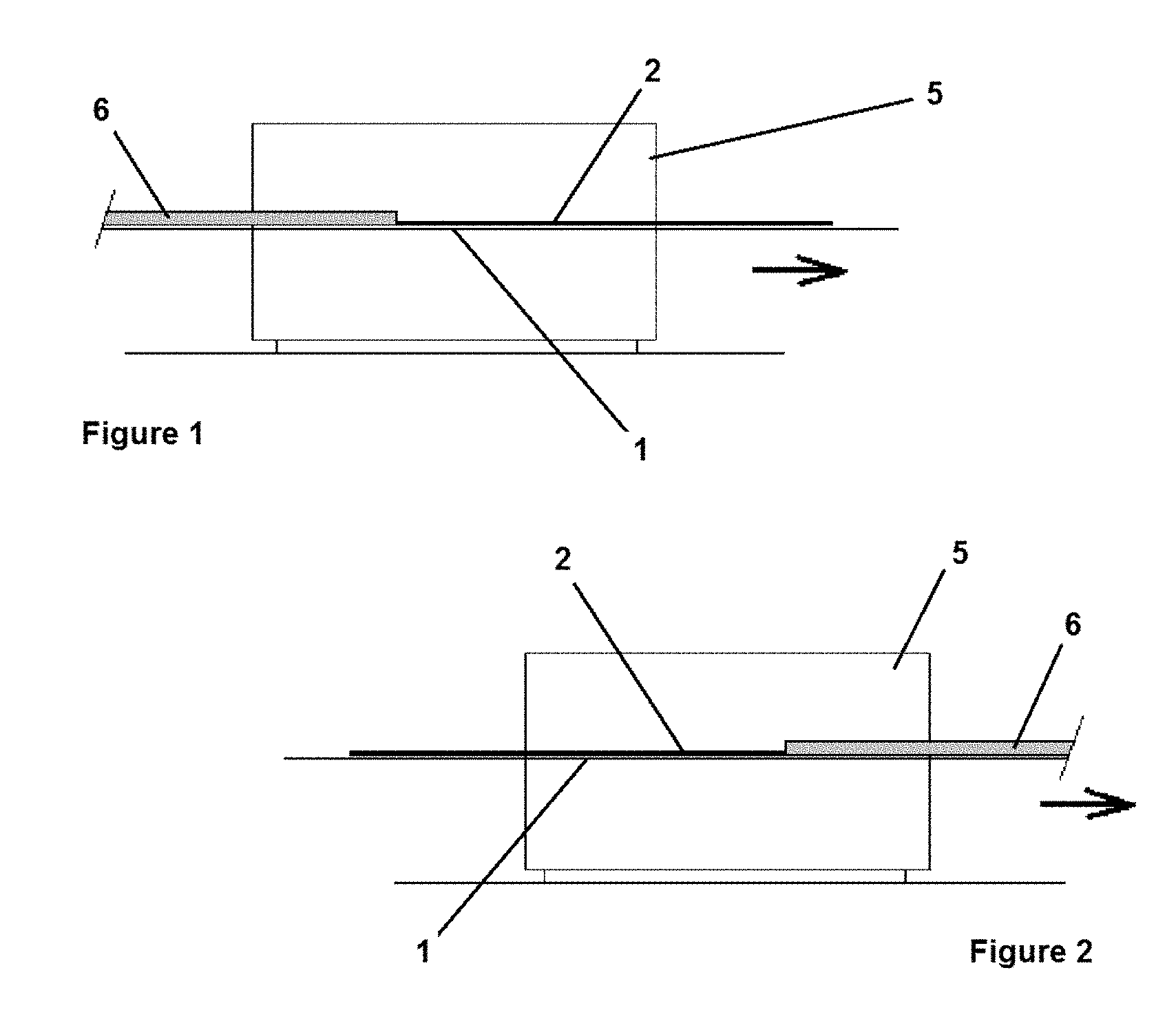
[0020] FIG. 1 is a schematic representation of a variant of the device of the invention downstream of the wire to be treated,
[0021] FIG. 2 is a schematic representation of a variant of the device of the invention upstream of the wire to be treated,
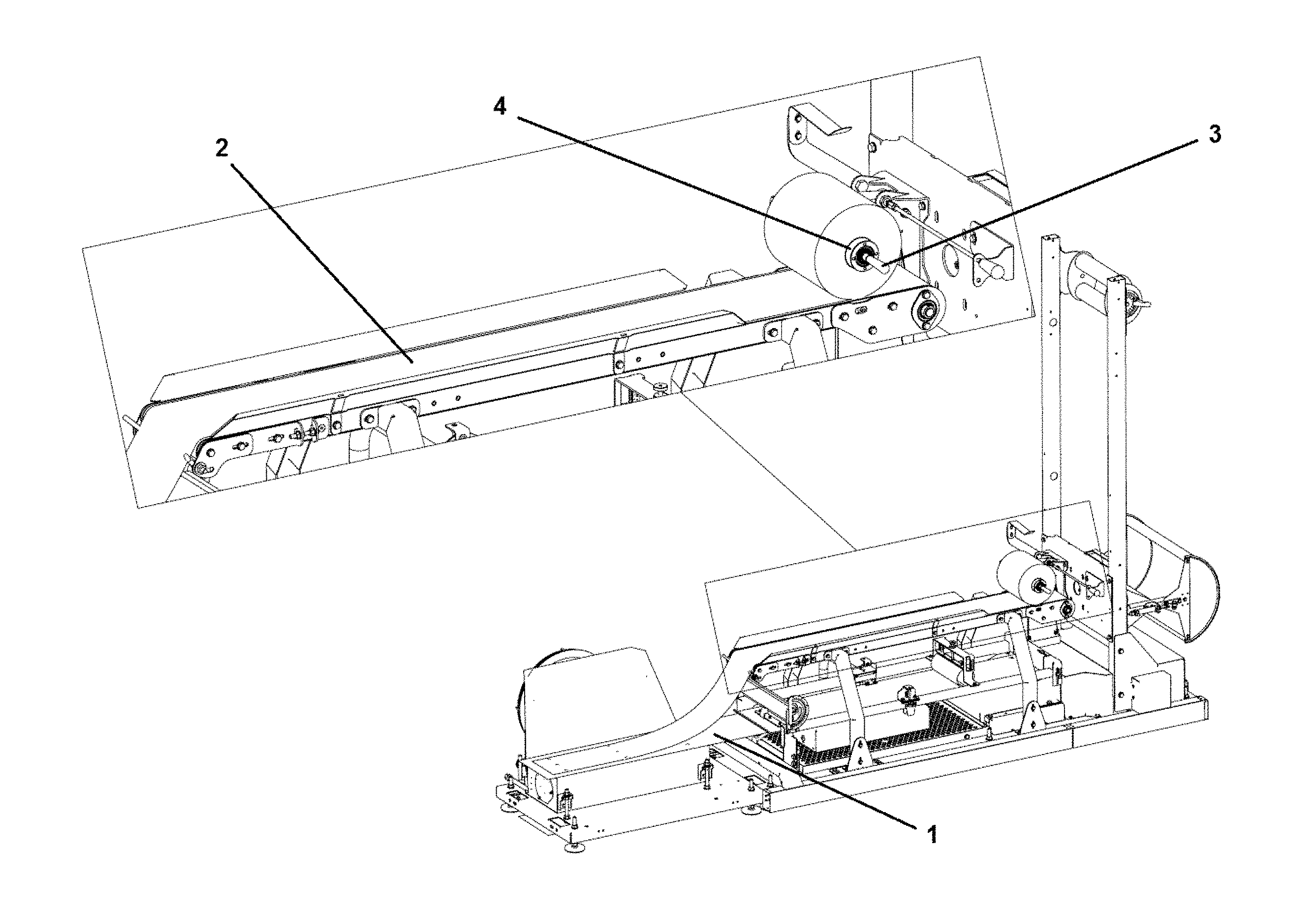
[0022] FIGS. 3 and 3b are schematic and detailed representations of an example of a mechanism for the recovery of a heat distribution management device according to the invention.
DETAILED DESCRIPTION
[0023] In this document, the terms "downstream" and "upstream" define positions in relation to the direction of movement of a wire being treated and/or of a wire on a means of transport 1 of the treatment device 5.
[0024] This invention relates to a heat distribution management device in a treatment device 5 of wires 6 in movement on a means of transport 1, said means of transport 1 being able to be traversed by a flow of heat at or through the orifices, characterized in that the device comprises at least one means of sealing 2 by coverage of at least one part of the orifices of the means of transport 1, this means of sealing 2 being independent of the means of transport.
[0025] The means of sealing 2 of the device is intended to take the place of a wire or a wire bundle 6, upstream and/or downstream of the wire or wire bundle 6 that is to be treated, during the treatment of the wire 6 placed on the means of transport 1 in the treatment device 5 of the wires 6. This means of sealing 2 thereby allows the coverage of the orifices of the means of transport 1 in a manner similar to that of an equivalent wire or wire bundle 5 which would be positioned upstream or downstream of the wire or wire bundle 5 to be treated. Furthermore, the movement of the flows of heat or of steam through the part of the means of transport 1 which does not carry the wire or the wire bundle 6 is limited, or even precluded, in the same manner as if the part of the means of transport 1 was carrying a wire or wire bundle 6.
[0026] As a consequence, the distribution of the flows of heat or of steam is homogenized over the whole of the wire 6 part that is undergoing treatment on the means of transport 1 in the heat treatment device 5.
[0027] According to an embodiment feature of the management device of the invention, the means of sealing 2 is realized in the form of a fabric belt or of a wire bundle. The choice of the means of sealing 2 is taken on the basis of the type of wire or of wire bundles 6 treated upstream and/or downstream of the means of sealing 2. Furthermore, on top of the width of the distribution of the placement of the wire or of the wire bundles 6 on the means of transport 1, that are to be considered to select the means of sealing 2, it is likewise important to consider the propensity of the treated wire or wire bundles 6 to be traversed by a flow of heat or of steam.
[0028] Thus, the means of sealing 2 is selected on the basis of the sealing or to the contrary permeable nature of the treated wire or wire bundles 6 for the passage of a flow of heat or of steam in order to optimize the homogeneity of the distribution of the flows in the treatment device 5 of the wires 6.
[0029] According to a construction feature, the heat distribution management device is characterized in that the length of the device is adapted to be at least equal to the cumulative length of the whole of the means 1 participating in the transport of wires 6 in the treatment device 5 of the wires 6. This construction feature allows for a device, according to the invention, of which the means of sealing 2 is sufficiently long to seal the whole of the means of transport 1 of wires in the treatment device 5, before and/or after the treatment of the wire or of the wire bundle 6.
[0030] According to a construction feature that is complementary and/or alternative to the preceding construction feature, the heat distribution management device is characterized in that the length of the device is adapted to be at least equal to the length traveled by a wire 6 in the treatment device 5 of the wires 6. This construction feature allows for a device according to the invention the length of which is best adapted to the path followed by the wire or wire bundle 6 in the treatment device 5. Indeed, in particular when the wire 6 is caused to be transferred from one means of transport 1 to another, it can occur that the length of the path followed by the wire 6 is different from the cumulative length of the means of transport 1. Thus, when the wire or wire bundle 6 does not move over the whole of the length of the means of transport 1, the length of the path of the wire 6 is shorter than that of the cumulative length of the means of transport 1. Conversely, when the wire or wire bundle 6 is transferred from one means of transport 1 to another by means of a drop between the two means of transport 1, the length of the fall increases the path of the wire or wire bundle 6 in relation to the distance of movement undertaken on the sole means of transport 1.
[0031] According to another construction feature of the device of the invention, the width of the device substantially corresponds to the width of the whole of the wires 6 to be treated by the treatment device 5. In a complementary manner, the width of the device corresponds to the width of the spread of the wire bundle 6 on the surface of the means of transport 1.
[0032] According to another construction feature of the device of the invention, the device comprises at least one fastener of the means of sealing 2 to one end of a wire or of one wire bundle 6. This fastener is preferably associated with the means of sealing 2 at its end. Thus, the fastener maintains the fastening of the wire or wire bundle 6 with the means of sealing 2 over the whole of the path of treatment in the heat treatment device. The risks of discontinuity between the wire or wire bundle 6 and the means of sealing 2 are reduced and the quality of the distribution of the heat and/or steam flows in the heat treatment device 5 is maintained.
[0033] The invention moreover relates to an implementation process of at least one heat distribution management device according to the invention, characterized in that the process comprises: [0034] a stage involving placement of the heat distribution management device on a means of transport 1 at the inlet opening of the treatment device 5 of the wires 6, [0035] a stage involving distribution of the management device on at least one part of the width of the means of transport 1.
[0036] According to an implementation feature, the process according to the invention is characterized in that it comprises: [0037] a stage involving movement of the heat distribution management device on a means of transport 1 and a subsequent driving of a least one wire 6 to be treated, [0038] a stage involving occupation by the heat distribution management device and at least one wire 6 to be treated, of the length of the whole of the path of the wire 6 to be treated on the means of transport 1 of the treatment device 5 of the wires 6.
[0039] According to an alternative implementation feature, the process according to the invention is characterized in that it comprises: [0040] a stage involving movement of the heat distribution management device on a means of transport 1 being subsequently driven by at least one wire 6 to be treated, [0041] a stage involving occupation by the heat distribution management device and at least one wire 6 to be treated, of the length of the whole of the path of the wire 6 to be treated on the means of transport 1 of the treatment device 5 of the wires 6.
[0042] The invention furthermore relates to a mechanism for the recovery of a heat distribution management device according to the invention, characterized in that the recovery mechanism, which is able to be positioned at the outlet of the treatment device 5 of the wires 6, comprises at least: [0043] one fastening interface to at least one end of the management device, [0044] one pivot axis 3 upon which the fastening interface is mounted, [0045] one device for coiling 4 around the pivot axis 3, [0046] one device for adjustment of the coiling speed on the basis of the speed of movement of at least one means of transport 1 of the treatment device 5 of the wires 6.
[0047] According to a construction feature of the recovery mechanism, the fastening interface is arranged to interact with an end of the means of sealing 2 of the management device.
[0048] According to another construction feature of the mechanism, the adjustment of the coiling speed is carried out on the basis of the speed of movement of the last means of transport 1 which carries the management device of the invention.
[0049] Let it be clear that the invention is not limited to the embodiment described and represented in the appended drawings. Modifications remain possible, in particular, from the point of view of the make-up of the various elements or through substitution of equivalent techniques without however leaving the scope of protection of the invention.
* * * * *
D00000
D00001
D00002
XML
uspto.report is an independent third-party trademark research tool that is not affiliated, endorsed, or sponsored by the United States Patent and Trademark Office (USPTO) or any other governmental organization. The information provided by uspto.report is based on publicly available data at the time of writing and is intended for informational purposes only.
While we strive to provide accurate and up-to-date information, we do not guarantee the accuracy, completeness, reliability, or suitability of the information displayed on this site. The use of this site is at your own risk. Any reliance you place on such information is therefore strictly at your own risk.
All official trademark data, including owner information, should be verified by visiting the official USPTO website at www.uspto.gov. This site is not intended to replace professional legal advice and should not be used as a substitute for consulting with a legal professional who is knowledgeable about trademark law.