Methods Of Forming A Porous Thermal Barrier Coating
Grossman; Theodore Robert ; et al.
U.S. patent application number 15/830062 was filed with the patent office on 2019-06-06 for methods of forming a porous thermal barrier coating. The applicant listed for this patent is GENERAL ELECTRIC COMPANY. Invention is credited to Theodore Robert Grossman, Joshua Lee Margolies.
| Application Number | 20190169730 15/830062 |
| Document ID | / |
| Family ID | 64572135 |
| Filed Date | 2019-06-06 |


| United States Patent Application | 20190169730 |
| Kind Code | A1 |
| Grossman; Theodore Robert ; et al. | June 6, 2019 |
METHODS OF FORMING A POROUS THERMAL BARRIER COATING
Abstract
A method for controlling the porosity parameter of porous thermal barrier coatings is presented. The method includes disposing a feedstock material on a substrate to form a porous thermal barrier coating. The feedstock material includes a gas-forming additive and a thermal barrier coating material. The disposing step further includes controlling the porosity parameter of the porous thermal barrier coating by controlling a feedstock material feed rate, an amount of the gas-forming additive in the feedstock material, a temperature of the disposed feedstock material on the substrate, or combinations thereof.
| Inventors: | Grossman; Theodore Robert; (Cincinnati, OH) ; Margolies; Joshua Lee; (Niskayuna, NY) | ||||||||||
| Applicant: |
|
||||||||||
|---|---|---|---|---|---|---|---|---|---|---|---|
| Family ID: | 64572135 | ||||||||||
| Appl. No.: | 15/830062 | ||||||||||
| Filed: | December 4, 2017 |
| Current U.S. Class: | 1/1 |
| Current CPC Class: | C23C 4/02 20130101; C23C 4/134 20160101; C23C 4/11 20160101; C23C 4/18 20130101 |
| International Class: | C23C 4/134 20060101 C23C004/134 |
Claims
1. A method of forming a porous thermal barrier coating, comprising: disposing a feedstock material on a substrate to form the porous thermal barrier coating, wherein the feedstock material comprises a gas-forming additive and a thermal barrier coating material, and wherein the disposing comprises controlling a porosity parameter of the porous thermal barrier coating by controlling a feedstock material feed rate, an amount of the gas-forming additive in the feedstock material, a temperature of the disposed feedstock material on the substrate, or combinations thereof.
2. The method according to claim 1, wherein the controlling the porosity parameter of the porous thermal barrier coating comprises controlling the temperature of the disposed feedstock material on the substrate using an auxiliary heat source.
3. The method according to claim 1, wherein the disposed feedstock material on the substrate is heated to a temperature greater than a temperature that the substrate can withstand. Amend to claim 1 and include.
4. The method according to claim 3, wherein the disposed feedstock material on the substrate is heated to a temperature in a range from about 1000.degree. C. to about 1500.degree. C.
5. The method according to claim 1, wherein the controlling the porosity parameter of the porous thermal barrier coating comprises controlling the amount of the gas-forming additive in the feedstock material in a range from about 0.1 wt % to about 10 wt %.
6. The method according to claim 1, wherein the controlling the porosity parameter of the porous thermal barrier coating comprises controlling the feedstock material feed rate in a range from about 2.5 gm/min to about 100 gm/min.
7. The method according to claim 1, wherein the gas-forming additive comprises graphite, carbides, oxycarbides, nitrides, or combinations thereof.
8. The method according to claim 1, wherein the gas-forming additive comprises elemental carbon.
9. The method according to claim 1, wherein the thermal barrier coating material comprises yttria-stabilized zirconia.
10. The method according to claim 1, wherein the feedstock material is disposed on the substrate using an air plasma spray process.
11. The method according to claim 1, wherein the porosity parameter comprises an average pore size, an average pore volume, a pore size distribution, a pore microstructure, or combinations thereof.
12. The method according to claim 1, wherein the porous thermal barrier coating comprises a plurality of pores such that at least some pores of the plurality of pores are intragranular.
13. The method according to claim 1, wherein the controlling the porosity parameter of the porous thermal barrier coating comprises controlling an average pore size of a plurality of pores in the porous thermal barrier coating in a range from about 0.1 microns to about 25 microns.
14. The method according to claim 1, wherein the controlling the porosity parameter of the porous thermal barrier coating comprises controlling an average pore volume of a plurality of pores in the porous thermal barrier coating in a range from about 5 volume % to about 10 volume %.
15. The method according to claim 1, wherein the controlling the porosity parameter of the thermal barrier coating further comprises forming a graded porosity across a thickness of the thermal barrier coating.
16. A method of forming a porous thermal barrier coating, comprising: disposing a feedstock material using an air plasma spray process on a substrate to form the porous thermal barrier coating, wherein the feedstock material comprises a gas-forming additive and a thermal barrier coating material, and wherein the disposing comprises controlling a porosity parameter of the porous thermal barrier coating by controlling a temperature of the disposed feedstock material on the substrate using an auxiliary heat source.
17. The method according to claim 16, wherein the disposed feedstock material on the substrate is heated to a temperature in a range from about 1000.degree. C. to about 1500.degree. C.
18. The method according to claim 16, wherein the gas-forming additive comprises elemental carbon.
19. The method according to claim 16, wherein the thermal barrier coating material comprises yttria-stabilized zirconia.
20. A method of forming a porous thermal barrier coating comprising a graded porosity, the method comprising: disposing a feedstock material on a substrate to form the porous thermal barrier coating, wherein the feedstock material comprises a gas-forming additive and a thermal barrier coating material, and wherein the disposing comprises forming the graded porosity in the thermal barrier coating by controlling: an amount of the gas-forming additive in the feedstock material, a temperature of the disposed feedstock material on the substrate using an auxiliary heat source, or a combination thereof.
Description
BACKGROUND
[0001] The disclosure relates generally to methods for forming porous thermal barrier coatings. More particularly, the disclosure relates to controlling a porosity parameter of porous thermal barrier coatings.
[0002] Thermal barrier coatings are typically used in articles that operate at or are exposed to high temperatures. Aviation turbines and land-based turbines, for example, may include one or more components protected by the thermal barrier coatings. Examples of materials used for thermal barrier coatings include rare earth-stabilized zirconia materials such as yttrium-stabilized zirconia (YSZ). Rare earth stabilized zirconia materials have a thermal conductivity of about 2.2 W/m-K when evaluated as a dense sintered compact. The YSZ is widely used as a thermal barrier coating material in gas turbines, in part, because of its high temperature capability, low thermal conductivity, and relative ease of deposition. In recent years, there has been a growing demand for further improvements in the thermal barrier properties to decrease the overall weight, thickness, and amount of materials used to form thermal barrier coatings.
[0003] The thermal conductivity of thermal barrier coatings may also be reduced by increasing the porosity of the coatings. Conventionally thermal barrier coatings may be formed using suitable deposition techniques, such as, for example, by air plasma spraying (APS) or by electron beam physical vapor deposition (EPVD). Thermal barrier coatings deposited by the APS process may typically have a microstructure characterized by irregular fattened grains surrounded by inhomogeneous porosity. Thermal barrier coatings deposited by the EBPVD process may yield a columnar, strain-tolerant grain structure that may be able to expand and contract without causing stresses that lead to spallation. However, the EBPVD process may be more capital intensive than the APS process. Therefore, there is a need for improved coating processes that enable control over the porosity of the thermal barrier coatings, thereby controlling the thermal conductivity of the thermal barrier coatings.
BRIEF DESCRIPTION
[0004] One embodiment of the disclosure is directed to a method of forming a porous thermal barrier coating by disposing a feedstock material on a substrate. The feedstock material includes a gas-forming additive and a thermal barrier coating material. The disposing step further includes controlling a porosity parameter of the porous thermal barrier coating by controlling the feedstock material feed rate, an amount of the gas-forming additive in the feedstock material, the temperature of the disposed feedstock material on the substrate, or combinations thereof.
[0005] Another embodiment of the disclosure is directed to a method of forming a porous thermal barrier coating by disposing a feedstock material using an air plasma spray process on a substrate. The feedstock material includes a gas-forming additive and a thermal barrier coating material. The disposing step further includes controlling a porosity parameter of the porous thermal barrier coating by controlling the temperature of the disposed feedstock material on the substrate using an auxiliary heat source.
[0006] Another embodiment of the disclosure is directed to a method of forming a porous thermal barrier coating including a graded porosity. The method includes disposing a feedstock material on a substrate to form the porous thermal barrier coating, wherein the feedstock material includes a gas-forming additive and a thermal barrier coating material. The disposing includes forming the graded porosity in the thermal barrier coating by controlling an amount of the gas-forming additive in the feedstock material, a temperature of the disposed feedstock material on the substrate using an auxiliary heat source, or a combination thereof.
DRAWINGS
[0007] These and other features, aspects, and advantages of the present disclosure will become better understood when the following detailed description is read with reference to the accompanying drawings, in which like characters represent like parts throughout the drawings, wherein:
[0008] FIG. 1 illustrates a method of forming a porous thermal barrier coating, in accordance with an embodiment of the disclosure;
[0009] FIG. 2 illustrates a method of forming a porous thermal barrier coating, in accordance with an embodiment of the disclosure.
[0010] FIG. 3 illustrates a method of forming a porous thermal barrier coating, in accordance with an embodiment of the disclosure.
[0011] FIG. 4 illustrates a sectional view of a schematic of a porous thermal barrier coating, in accordance with an embodiment of the disclosure;
[0012] FIG. 5 illustrates another sectional view of a schematic of a porous thermal barrier coating, in accordance with an embodiment of the disclosure; and
[0013] FIG. 6 illustrates a scanning electron microscope (SEM) photomicrograph of a porous thermal barrier coating, in accordance with an embodiment of the disclosure.
DETAILED DESCRIPTION
[0014] Approximating language, as used herein throughout the specification and claims, may be applied to modify any quantitative representation that could permissibly vary without resulting in a change in the basic function to which it is related. Accordingly, a value modified by a term such as "about" is not to be limited to the precise value specified. In some instances, the approximating language may correspond to the precision of an instrument for measuring the value. Here and throughout the specification and claims, range limitations may be combined and/or interchanged, such ranges are identified and include all the sub-ranges contained therein unless context or language indicates otherwise.
[0015] In the following specification and the claims, the singular forms "a", "an" and "the" include plural referents unless the context clearly dictates otherwise. As used herein, the term "or" is not meant to be exclusive and refers to at least one of the referenced components being present and includes instances in which a combination of the referenced components may be present, unless the context clearly dictates otherwise.
[0016] As used herein, the terms "may" and "may be" indicate a possibility of an occurrence within a set of circumstances; a possession of a specified property, characteristic or function; and/or qualify another verb by expressing one or more of an ability, capability, or possibility associated with the qualified verb. Accordingly, usage of "may" and "may be" indicates that a modified term is apparently appropriate, capable, or suitable for an indicated capacity, function, or usage, while taking into account that in some circumstances, the modified term may sometimes not be appropriate, capable, or suitable.
[0017] As used herein, the term "coating" refers to a material disposed on at least a portion of an underlying surface in a continuous or discontinuous manner. Further, the term "coating" does not necessarily mean a uniform thickness of the disposed material, and the disposed material may have a uniform or a variable thickness. The term "coating" may refer to a single layer of the coating material or may refer to a plurality of layers of the coating material. The coating material may be the same or different in the plurality of layers.
[0018] As used herein, the term "disposed on" refers to layers or coatings disposed directly in contact with each other or indirectly by having intervening layers there between, unless otherwise specifically indicated.
[0019] One embodiment of the disclosure is directed to a method of forming a porous thermal barrier coating. The method includes disposing a feedstock material on a substrate to form the porous thermal barrier coating, wherein the feedstock material includes a gas-forming additive and a thermal barrier coating material. The disposing step includes controlling a porosity parameter of the porous thermal barrier coating by controlling a feedstock material feed rate, an amount of the gas-forming additive in the feedstock material, a temperature of the disposed feedstock material on the substrate, or combinations thereof.
[0020] FIG. 1 illustrates a method 10 in accordance with some embodiments of the present disclosure. The method 10 includes providing a substrate 110, at step 11, disposing a feedstock material 121 on the substrate 110 to form a disposed feedstock material 120, at step 12, and forming a porous thermal barrier coating 130 on the substrate 110, at step 13.
[0021] It should be noted that although in FIG. 1, the substrate 110 is shown has having a planar profile for ease of illustration, the substrate 110 may have any suitable geometry or profile, for example, a complex geometry, a non-planar profile, or a combination of both. As used herein, the term "complex geometry" refers to shapes not easily or consistently identifiable or reproducible, such as, not being square, circular, or rectangular. In some embodiments, the substrate 110 may be a part of a component exposed to a high temperature environment, for example, a turbine engine. In some embodiments, the turbine engine may be an aircraft engine. Alternatively, the turbine engine may be any other type of engine used in industrial applications. Non-limiting examples of such turbine engines include a land-based turbine engine employed in a power plant, a turbine engine used in a marine vessel, or a turbine engine used in an oil rig. Non-limiting examples of turbine engine components include turbine airfoils such as blades and vanes, turbine shrouds, turbine nozzles, buckets, combustor components such as liners and deflectors, heat shields, augmentor hardware of gas turbine engines, and other similar turbine components known to those skilled in the art.
[0022] The substrate 110 may include a ceramic matrix composite or a metallic superalloy. Non-limiting examples of suitable metallic superalloys include iron-based superalloys, cobalt based superalloys, nickel based superalloys, or combinations thereof.
[0023] The substrate 110 may be a pre-fabricated component of a turbine engine, or, may be manufactured before the disposing step. In some embodiments, the step 11, of providing the substrate may include one or more preparatory steps, for example, cleaning, polishing, disposing a bond coating, and the like. In some embodiments, the substrate 110 may be coated with a bond coating (not shown in Figures), at step 11. The bond coating may be formed from a metallic oxidation-resistant material that protects the underlying substrate 110 and enables the porous thermal barrier coating 130 to more tenaciously adhere to substrate 110. Suitable materials for the bond coating include M.sub.1CrAlY alloy powders, where M.sub.1 represents a metal such as iron, nickel, platinum or cobalt. Non-limiting examples of other suitable bond coat materials include metal aluminides such as nickel aluminide, platinum aluminide, or a combination thereof.
[0024] As mentioned earlier, the feedstock material 121 is disposed on the substrate 110 to form a disposed feedstock material 120, at step 12. As used herein, the term "feedstock material" refers to a homogenous mixture of two or more materials forming a single phase, or, alternatively, to a heterogenous mixture of two or more materials forming more than one phase. The feedstock material 121 may be in a solid form, in a liquid form, or in a semi-solid form. In certain embodiments, the feedstock material 121 is in the form of a powder.
[0025] As stated earlier, the feedstock material 121 includes a gas-forming additive and a thermal barrier coating material. In certain embodiments, the feedstock material 121 includes a homogeneous mixture of the gas-forming additive and the thermal barrier coating material. In certain embodiments, the gas-forming additive is pre-dissolved into the thermal barrier coating material to form the feedstock material 121. Without being bound by any theory, it is believed that by incorporating the gas-forming additive in the feedstock material 121 at the time of fabrication of the feedstock material 121 (for example, a feedstock powder), a porosity parameter of the porous thermal barrier coating 130 may be controlled. For example, by controlling one or more of the amount, the size, or the distribution of the gas-forming additive in the feedstock material 121.
[0026] As used herein, the term "gas-forming additive" refers to a material which, at an elevated temperature, is capable of oxidizing into a non-reactive and insoluble (with the thermal barrier coating material) gas that is entrapped by the thermal barrier coating material, thereby forming pores. Examples of suitable gas-forming additives include, but are not limited to, graphite, carbides, oxycarbides, nitrides, or combination thereof. In certain embodiments, the gas forming additive includes elemental carbon. As described in detail later, during or after the disposing step, the gas forming additive forms a gas, for example, carbon monoxide, carbon dioxide, nitrous oxide, or any suitable gas depending on the composition of the gas-forming additive employed. The insoluble gas is entrapped in the thermal barrier coating during the disposing or the post-disposing steps, thereby forming pores. In some embodiments, a substantial amount of the gas formed is entrapped in the thermal barrier coating material. The term "substantial amount of the gas" as used herein refers to at least 90 volume % of the gas formed. This is in contrast to fugitive materials employed to form porous coatings, wherein the coating materials are subjected to elevated temperatures such that the fugitive materials decompose or oxidize, and the resulting gases are expelled from the coatings, thereby resulting in pores.
[0027] As used herein, the term "thermal barrier coating" refers to a coating that includes a material capable of reducing heat flow to the underlying substrate of the article, that is, form a thermal barrier. The composition of the porous thermal barrier coating in terms of the type and amount of the thermal barrier coating materials may depend upon one or more factors, including the composition of the adjacent bond coat layer (if present), the coefficient of thermal expansion (CTE) characteristics desired for the thermal barrier coating, and the thermal barrier properties desired for the thermal barrier coating.
[0028] Non-limiting examples of suitable thermal barrier coating materials include zirconias, pyrochlores, or combinations thereof. In some embodiments, the thermal barrier material includes chemically stabilized zirconias (for example, metal oxides blended with zirconia), such as yttria-stabilized zirconias, ceria-stabilized zirconias, calcia-stabilized zirconias, scandia-stabilized zirconias, magnesia-stabilized zirconias, india-stabilized zirconias, ytterbia-stabilized zirconias, lanthana-stabilized zirconias, gadolinia-stabilized zirconias, as well as mixtures of such stabilized zirconias.
[0029] In certain embodiments, the thermal barrier coating material includes yttria-stabilized zirconias. Suitable yttria-stabilized zirconias may include from about 1 wt % to about 20 wt % yttria (based on the combined weight of yttria and zirconia), and more typically from about 3 wt % to about 10 wt % yttria. An example yttria-stabilized zirconia thermal barrier coating includes about 7 wt % yttria and about 93 wt % zirconia. These chemically stabilized zirconias may further include one or more of a second metal (e.g., a lanthanide or actinide) oxide such as dysprosia, erbia, europia, gadolinia, neodymia, praseodymia, urania, and hafnia to further reduce thermal conductivity of the thermal barrier coating.
[0030] As used herein, the term "porous thermal barrier coating" refers to a coating including a plurality of pores. The term "porosity parameter of the porous thermal barrier coating" as used herein refers to one or more of pore size, pore size distribution, number of pores, or pore microstructure of the plurality of pores, in the porous thermal barrier coating 130. The pore size provides an indication of the median or average size of the pores in the porous thermal barrier coating 130. The pore size distribution provides a quantitative description of the range of pore sizes present across the length, breadth and thickness of the porous thermal barrier coating 130. Pore volume is the percentage of volume occupied by the plurality of pores in the total volume occupied by the porous thermal barrier coating 130, and is also referred to as the "total porosity" of the porous thermal barrier coating 130. By varying one of more of the aforementioned porosity parameters, the total porosity of the plurality of pores in the porous thermal barrier coating 130 may be controlled. One or more of the pore size, the pore shape, the number of pores, the pore size distribution, or the pore microstructure in the porous thermal barrier coating 130 may be controlled using the methods described in the present disclosure.
[0031] In some embodiments, an average pore size of the plurality of pores in the porous thermal barrier coating 130 is in a range from about 0.1 microns to about 25 microns. In some embodiments, an average pore size of the plurality of pores in the porous thermal barrier coating 130 is in a range from about 0.25 microns to about 5 microns. The plurality of pores in the porous thermal barrier coating 130 may be characterized any suitable shape. In certain embodiments, the shape of the pores in the porous thermal barrier coating may be substantially spherical. In some embodiments, spheroidal porosity in the porous thermal barrier coating 130 may provide a strain tolerant microstructure, thereby allowing the thermal barrier coating to operate under the gas turbine operating conditions for much longer periods.
[0032] Referring again to FIG. 1, at step 12, the feedstock material 121 is disposed on the substrate 110 using a suitable apparatus 115. The feedstock material 121 may be disposed on a bond coating (if present) or on the substrate 110 directly by any of a variety of techniques, including vapor disposition, such as physical vapor deposition (PVD), electron beam physical vapor deposition (EBPVD); plasma spray, such as air plasma spray (APS), suspension plasma spray (SPS), and vacuum plasma spray (VPS); other thermal spray deposition methods such as high velocity oxy-fuel (HVOF) spray, detonation, or wire spray; chemical vapor deposition (CVD), sol-gel method, or combinations of two or more of the afore-mentioned techniques.
[0033] The particular technique used for disposing, depositing or otherwise forming the porous thermal barrier coating 130 may depend on one or more of the composition of the porous thermal barrier coating 130, the thickness, and the physical structure desired for the porous thermal barrier coating 130. In certain embodiments, the feedstock material 121 is disposed using plasma spray techniques, in particular, APS technique. As mentioned earlier, the gas-forming additive and the thermal barrier coating material is co-deposited as a feedstock material 121 on the substrate 110 or the bond coating (if present). In some embodiments, co-depositing may be achieved by blending, mixing or otherwise combining the gas-forming additive and the thermal barrier coating material together (for example, as powders) to provide a mixture that is then deposited onto substrate/bond coating. The blending or mixing of the gas-forming additive and the thermal barrier coating material may be effected prior to providing the feedstock material to the deposition apparatus 115 (for example, an APS gun), or may be effected in the deposition apparatus 115 itself, therein forming the feedstock material. In certain embodiments, the gas-forming additive is mixed and dissolved in the thermal barrier coating material prior to providing the feedstock material 121 to the deposition apparatus 115. The term "disposed feedstock material" as used herein refers to an as-deposited feedstock material, i.e., feedstock material that has not been subjected to additional steps (e.g., heating), or, alternately to a feedstock material that has been subjected to additional steps (e.g., heating via an auxiliary heat source) after the disposing step. The term "disposed feedstock material" as used herein is differentiated from a "porous thermal barrier coating" such that in the "disposed feedstock material" the thermal barrier coating material is in a partially or completely molten state, and the pores may still not be entrapped within the coating.
[0034] The disposing step 12 further includes controlling the feedstock material 121 feed rate, an amount of the gas-forming additive in the feedstock material 121, or the temperature of the disposed feedstock material 120 on the substrate 110 to form a porous thermal barrier coating 130. By controlling one or more of these parameters, the porosity parameter (and therefore, a total porosity) of the porous thermal barrier coating 130 is controlled. Without being bound by any theory, it is believed that, in the absence of this controlling step, an uncontrolled, non-spheroidal, or randomly distributed porosity in the porous thermal barrier coating 130 may result.
[0035] In some embodiments, the porosity parameter of the porous thermal barrier coating 130 is controlled by controlling one or both a feedstock material 121 feed rate and an amount of the gas-forming additive in the feedstock material 121. The term "feed rate" as used herein refers to rate of deposition of the feedstock material 121 on the substrate 110, using a suitable deposition apparatus 115. In embodiments, wherein the feedstock material is deposited using the APS process, the term "feed rate" refers to the spray rate of the feedstock material 121. In some embodiments, the porosity parameter of porous thermal barrier coating 130 is controlled by controlling an amount of the gas-forming additive in the feedstock material 121 in a range from about 0.1 wt % to about 10 wt %. In some embodiments, the porosity parameter of porous thermal barrier coating 130 is controlled by controlling an amount of the gas-forming additive in the feedstock material 121 in a range from about 0.5 wt % to about 5 wt %. In some embodiments, as described in detail later, the amount of gas-forming additive in the feedstock material 121 may be varied over the duration of the disposing step such that the disposed feedstock material 120 includes a graded content of the gas-forming additive, thereby forming a graded porosity in the resultant porous thermal barrier coating 130. In such embodiments, the term "amount of gas-forming additive" refers to an average amount of gas-forming additive in the feedstock material 121 over the entire duration of the disposing step.
[0036] In some embodiments, the porosity parameter of porous thermal barrier coating 130 is controlled by controlling the feedstock material 121 feed rate in a range from about 2.5 gm/min to about 100 gm/min. In some embodiments, the porosity parameter of porous thermal barrier coating 130 is controlled by controlling the feedstock material 121 feed rate in a range from about 20 gm/min to about 50 gm/min. The feed rate may be controlled by using a valve or any other suitable method. This is in contrast to methods used to form porous thermal barrier coatings, wherein the feed rate or the amount of the gas-forming additive in the feedstock material are not controlled, which may result in uncontrolled and random porosity.
[0037] In some embodiments, the porosity parameter of porous thermal barrier coating 130 is controlled by controlling the temperature of the disposed feedstock material 120 on the substrate 110. The temperature of the disposed feedstock material 120 on the substrate 110 may be controlled by controlling one or more of the temperature of the feedstock material 121 before depositing (e.g., by pre-heating the feedstock material), temperature of deposition (e.g., the spray temperature if using APS for deposition or by using an auxiliary heat source during deposition); or the temperature of the substrate 110 on which the feedstock material is being deposited. In certain embodiments, the temperature of the disposed feedstock material 120 on the substrate 110 is controlled by a combination of pre-heating the substrate and by maintaining the disposed feedstock material temperature.
[0038] In some embodiments, the disposed feedstock material 120 on the substrate 110 is heated to a temperature greater than a temperature that the substrate 110 can withstand. As used herein, the term "temperature that the substrate can withstand" refers to a temperature beyond which the substrate may start to deform, melt, or change form. In some embodiments, the disposed feedstock material may be heated to a temperature similar to a turbine engine operating temperature. Depositing and heating the feedstock material to a temperature similar to the engine operating temperature may result in reduced coating stresses of the interface, while at that temperature, therefore, potentially improving the lifetime of the thermal barrier coating in the engine. In some embodiments, the disposed feedstock material 120 on the substrate 110 is heated to a temperature in a range from about 1000.degree. C. to about 1500.degree. C. In certain embodiments, the disposed feedstock material 120 on the substrate 110 is heated to a temperature in a range from about 1150.degree. C. to about 1300.degree. C.
[0039] The disposed feedstock material 120 may be heated using an auxiliary heat source. The term "auxiliary heat source" refers to a heat source employed in addition to the primary apparatus used for disposing the feedstock material 121. For example, when disposing the feedstock material using an APS technique, the APS apparatus may include a primary heat source that is distinct and separate from the auxiliary heat source. Suitable auxiliary heat sources include, but are not limited to, infrared (IR) sources, plasma sources, inductors, or combinations thereof. In some embodiments, the auxiliary heat source is a plasma source that is different from the plasma source used for the APS process. In certain embodiments, the auxiliary heat source includes an induction coil.
[0040] Another embodiment of the disclosure is directed to a method of forming a porous thermal barrier coating using an auxiliary heat source. The method includes disposing a feedstock material using an air plasma spray process on a substrate to form the porous thermal barrier coating, wherein the feedstock material includes a gas-forming additive and a thermal barrier coating material, and wherein the disposing step includes controlling a porosity parameter of the porous thermal barrier coating by controlling a temperature of the disposed feedstock material on the substrate using the auxiliary heat source.
[0041] FIG. 2 illustrates a method 20 in accordance with an embodiment of the present disclosure. The method 20 includes providing a substrate 110, at step 14; disposing a feedstock material using an APS apparatus 115 on the substrate 110 to form a disposed feedstock material 120, at step 15; and forming a porous thermal barrier coating 130 on the substrate 110, at step 16. The method further includes, controlling a temperature of the disposed feedstock material, at step 15, using an auxiliary heat source 125. Non-limiting examples of suitable auxiliary heat sources are described herein earlier. Further, it should be noted that although FIG. 2 illustrates a single auxiliary heat source 125, one or more heat sources 125 may be employed depending on the size and shape of the substrate. Furthermore, one or more of the configuration of the auxiliary heat source 125, the placement of the auxiliary heat source 125, and the proximity of the auxiliary heat source 125 to the substrate 110 may be varied depending on the degree of heating required.
[0042] Referring now to FIGS. 1 and 2, in some embodiments, the heating of the disposed feedstock material 120 is effected by one or more of pre-heating the substrate 110, simultaneously disposing and heating the feedstock material 121, or heating the disposed feedstock material 120 after the disposing step 12,15. In certain embodiments, the heating of the disposed feedstock material 120 is effected by pre-heating the substrate 110 prior to the disposing step 12,15. In some such instances, the substrate 110 may be pre-heated to a first temperature using the auxiliary heat source 125 and the feedstock material 121 may be deposited on the pre-heated substrate. The first temperature may be sufficient to melt the thermal barrier coating material or maintain an already molten thermal barrier coating material in the molten state, but lower than the temperature that the substrate 110 can withstand. In some embodiments, during the disposing step 12,15 the feedstock material may be further heated to a second temperature using the auxiliary heat source 125. The second temperature may be sufficient to result in oxidation of the gas-forming additive thereby forming a gas in the molten thermal barrier coating material, but greater than the temperature that the substrate can withstand. For example, for nickel or cobalt-based superalloys, the auxiliary heat source may heat the disposed feedstock material 120 to a temperature greater than the melting point of these superalloys, such that the gases are formed.
[0043] The method may further include cooling the disposed feedstock material 120 to form the porous thermal barrier coating 130, at step 13,16. In some embodiments, by employing a pre-heated substrate, the gas-forming additive containing feedstock material 121 is deposited at a temperature such that the gas-forming additive oxidizes and forms a gas. This gas may form while the feedstock material is still molten causing the gas bubbles to form pores. In some embodiments, the rate of cooling of the disposed feedstock material 120 is such that these pores are entrapped within the disposed feedstock material 120. As mentioned earlier, the porosity of these entrapped pores may be controlled using the methods described herein. In some embodiments, as described in detail later, the auxiliary heat source 125 may be further controlled such that the heating from the auxiliary heat source 125 may be effected to generate a graded porosity in the porous thermal barrier coating 130.
[0044] Another embodiment of the disclosure is directed to a method of forming a porous thermal barrier coating including a graded porosity. The method includes disposing a feedstock material on a substrate to form the porous thermal barrier coating, wherein the feedstock material includes a gas-forming additive and a thermal barrier coating material. The disposing includes forming the graded porosity in the thermal barrier coating by controlling an amount of the gas-forming additive in the feedstock material, a temperature of the disposed feedstock material on the substrate using an auxiliary heat source, or a combination thereof.
[0045] The term "graded porosity" as used herein refers to a variation in the volume percentage of the porous thermal barrier coating 130 occupied by the plurality of the pores, across a thickness of the porous thermal barrier coating 130. For a specific region of the porous thermal barrier coating 130, the volume percentage occupied by the plurality of the pores may be referred to as the "porosity" in that specific region. Further, the term graded porosity encompasses a discrete variation in porosity, a continuous variation in porosity, or a combination thereof. For example, in some embodiments, the method may include forming a graded porosity in the porous thermal barrier coatings 130 such that the porosity continuously increases or decreases across a thickness of the porous thermal barrier coating 130 from a region disposed proximate to the substrate 110 (or the bond coating if present) to a surface of the porous thermal barrier coating 130. In some other embodiments, the feedstock material 121 may be disposed on the substrate 110 (or the bond coating if present) in the form of discrete layers such that there is a step change (increase or decrease) of the porosity across the different layers of the resulting porous thermal barrier coating 130. In certain embodiments, the method includes forming a porous thermal barrier coating 130 such that regions proximate to the substrate 110 (or the bond coating if present) and the surface of the porous thermal barrier coating 130 may be substantially free of porosity. The intermediate region may have a graded porosity that may be discrete or continuous. Further the porosity in the intermediate region may increase or decrease depending on the desired properties of the porous thermal barrier coating. Without being bound by any theory, it is believed that a graded porosity across a thickness of the porous thermal barrier coating 130 may provide desired performance characteristics, depending on the end-use application. For example, by minimizing the porosity in a layer/region proximate to the surface of the porous thermal barrier coating, erosion or impact resistance of the coating may be enhanced. In some other applications, a porous surface of the thermal barrier coating may be desired, for example, to improve sacrificial properties of the coating.
[0046] The porosity of the porous thermal barrier coating 130 in different regions/layers of the thermal barrier coating 130 may be varied by varying one or both of a number of pores in the different regions/layers and an average size of the plurality of pores in the different regions/layers. In certain embodiments, a graded porosity across a thickness of the porous thermal barrier coating is formed by controlling an amount of the gas-forming additive in the feedstock material, a temperature of the disposed feedstock material on the substrate using an auxiliary heat source, or a combination thereof.
[0047] Referring back to FIGS. 1 and 2, in some embodiments, a graded porosity across a thickness of the porous thermal barrier coating 130 may be formed, for example, by controlling an amount of the gas-forming additive in the feedstock material 121. By varying the amount of the gas-forming additive in the feedstock material 121, the amount of gas-forming additive in the disposed feedstock material 120 over a duration of the disposing step 12, 15 may be varied. Therefore, resulting in a graded content of the gas-forming additive in disposed feedstock material 120. This graded content of the gas-forming additive in the disposed feedstock material 120, upon oxidation may result in a graded porosity. In some embodiments, the amount of gas-forming additive in the feedstock material 121 may be varied by providing a plurality of feeds to the deposition apparatus 115 with varying gas-forming additive content, and controlling the feed into the deposition apparatus 115.
[0048] With continued reference to FIG. 2, in some other embodiments, a graded porosity across a thickness of the porous thermal barrier coating 130 may be formed, for example, by controlling the temperature of the disposed feedstock material 120. In such embodiments, the auxiliary heat source 125 may be turned on or off, during the duration of the disposing step 15 depending on the desired gradation in porosity. For example, for layers/regions where minimal porosity is desired, the auxiliary heat source 125 may be turned off, thereby minimizing the formation of gases in those layers/regions.
[0049] Referring now to FIG. 3, a method 30 of forming a porous thermal barrier coating 130 with a graded porosity is illustrated. The method 30 includes providing a substrate 110, at step 31; disposing a thermal barrier coating material 112 on the substrate 110, at step 32; disposing a feedstock material 121 on the thermal barrier coating material 112 to form a plurality of layers of disposed feedstock material (120',120''), at step 33; disposing the thermal barrier coating material 112 on an outermost layer 120'' of the disposed feedstock material 120'', at step 34, and forming a porous thermal barrier coating 130 on the substrate 110, at step 35. The method further includes, controlling a temperature of the disposed feedstock material 120', 120'', at step 33, using an auxiliary heat source 125. Non-limiting examples of suitable auxiliary heat sources are described herein earlier. In some embodiments, the auxiliary heat source 125 may also be used in steps 32 and 34 to dispose the thermal barrier coating material 112 on the substrate 110. It should be noted that although FIG. 3 illustrates two layers of disposed feedstock material (120', 120''), multiple layers of disposed feedstock material may be present on the thermal barrier coating material 112 depending on the total porosity requirement.
[0050] In some embodiments, the amount of gas-forming additive in the disposed feedstock material 120' may be different than the amount in the disposed feedstock material 120''. As mentioned earlier, the amount of gas-forming additive in the disposed feedstock material 120 may be varied by varying an amount of the gas-forming additive in the feedstock material 121. This variation in the amount of gas-forming additive in different layers may lead to variation in the total porosity of each layer thereby producing the porous thermal barrier coating 130 with a graded porosity. Thus, in such embodiments, the porous thermal barrier coating 130 includes a plurality of layers (112, 120', 120'') such that the porosity of each layer is different.
[0051] In some embodiments, the temperature of the disposed feedstock material 120' may be different from a temperature of the disposed feedstock material 120''. As mentioned earlier, the temperature of the disposed feedstock material 120 may be varied by controlling the auxiliary heat source 125. This variation of the temperature in the different layers may lead to variation in the total porosity of each layer, thereby producing the porous thermal barrier coating 130 with a graded porosity. Thus, in such embodiments, the porous thermal barrier coating 130 includes a plurality of layers (112, 120', 120'') such that the porosity of each layer is different.
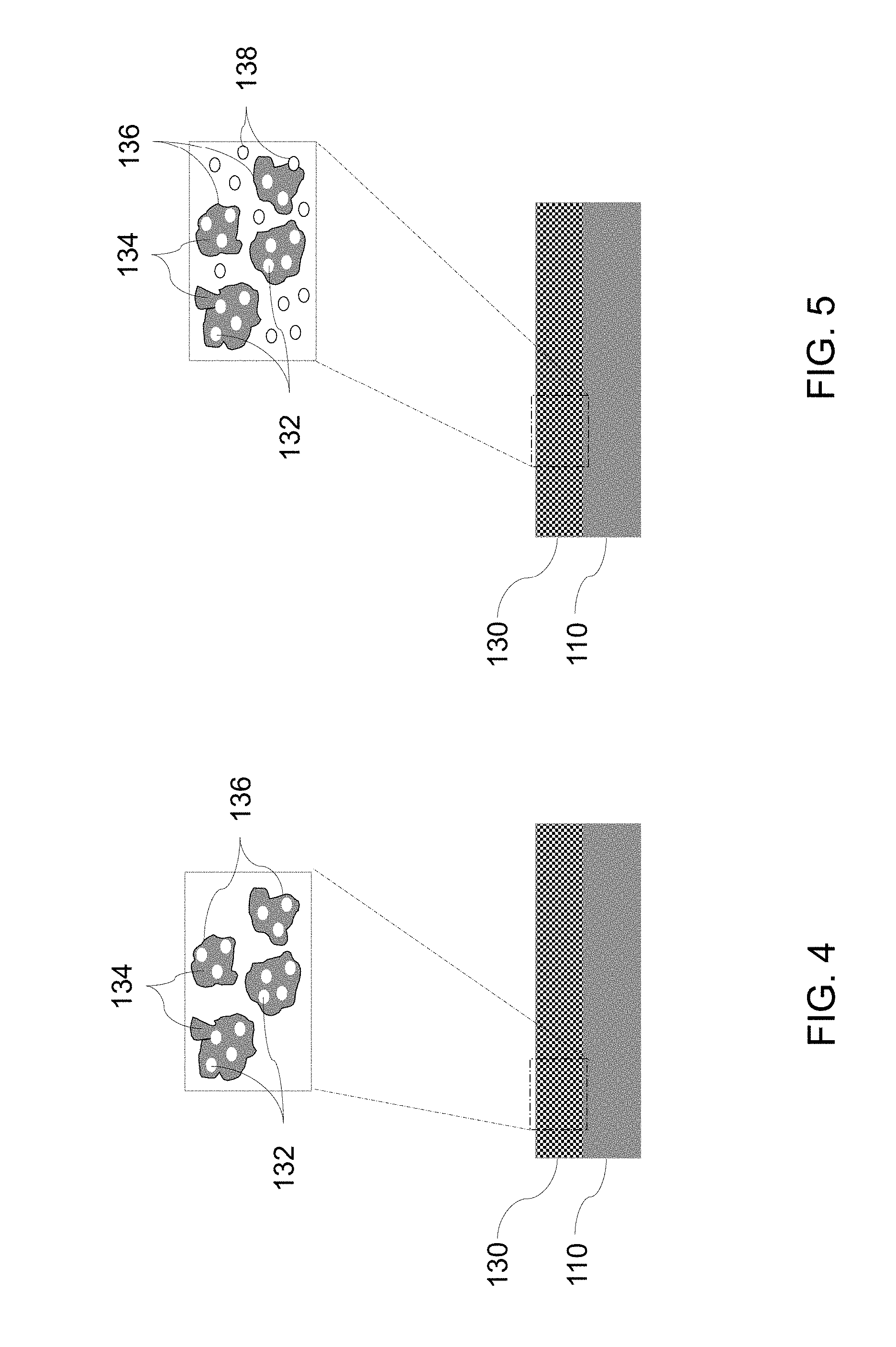
[0052] FIGS. 4 and 5 illustrate a sectional view of a schematic of a porous thermal barrier coating 130 including a plurality of pores 132, formed using the methods in accordance with some embodiments of the disclosure. In some embodiments, controlling the porosity parameter of the porous thermal barrier coating 130 includes controlling an average pore size of a plurality of pores 132 in the porous thermal barrier coating 130 in a range from about 0.1 microns to about 25 microns. In some embodiments, controlling the porosity parameter of the porous thermal barrier coating 130 includes controlling an average pore size of a plurality of pores 132 in the porous thermal barrier coating 130 in a range from about 0.25 microns to about 5 microns. In some embodiments, controlling the porosity parameter of the porous thermal barrier coating 130 includes controlling an average pore volume of a plurality of pores 132 in the porous thermal barrier coating 130 in a range from about 1 volume % to about 10 volume %. In some embodiments, controlling the porosity parameter of the porous thermal barrier coating 130 includes controlling an average pore volume of a plurality of pores 132 in the porous thermal barrier coating 130 in a range from about 5 volume % to about 10 volume %.
[0053] In some embodiments, controlling the porosity parameter of the porous thermal barrier coating 130 includes controlling the pore microstructure of the plurality of pores 132 in the porous thermal barrier coating 130. In some embodiments, the porous thermal barrier coating 130 includes a plurality of pores 132 such that at least some pores of the plurality of pores are intragranular. The term "intragranular" as used herein means that the pores are present inside the grains. In some embodiments, the porous thermal barrier coating 130 includes a plurality of pores 132 such that at least some pores of the plurality of pores are intergranular (present between the grains), or, present at the grain boundaries. In certain embodiments, greater than 50% of the plurality of pores are intragranular. In certain embodiments, greater than 80% of the plurality of pores are intragranular.
[0054] FIG. 4 illustrates a schematic of a microstructure of the porous thermal barrier coating 130 formed, in accordance with some embodiments of the present disclosure. The microstructure of the porous thermal barrier coating 130 as illustrated in FIG. 4 is characterized by grains 134 having a plurality of grain boundaries 136. The microstructure further includes plurality of pores 132 present inside the grains 134 (intragranular pores).
[0055] FIG. 5 illustrates another schematic of a microstructure of the porous thermal barrier coating 130 formed, in accordance with some embodiments of the present disclosure. The microstructure of the porous thermal barrier coating 130 as illustrated in FIG. 5 is characterized by grains 134 having a plurality of grain boundaries 136. The microstructure further includes plurality of pores 132 present inside the grains 134 (intragranular pores) and plurality of pores 138 at or between the grain boundaries 136 (intergranular pores).
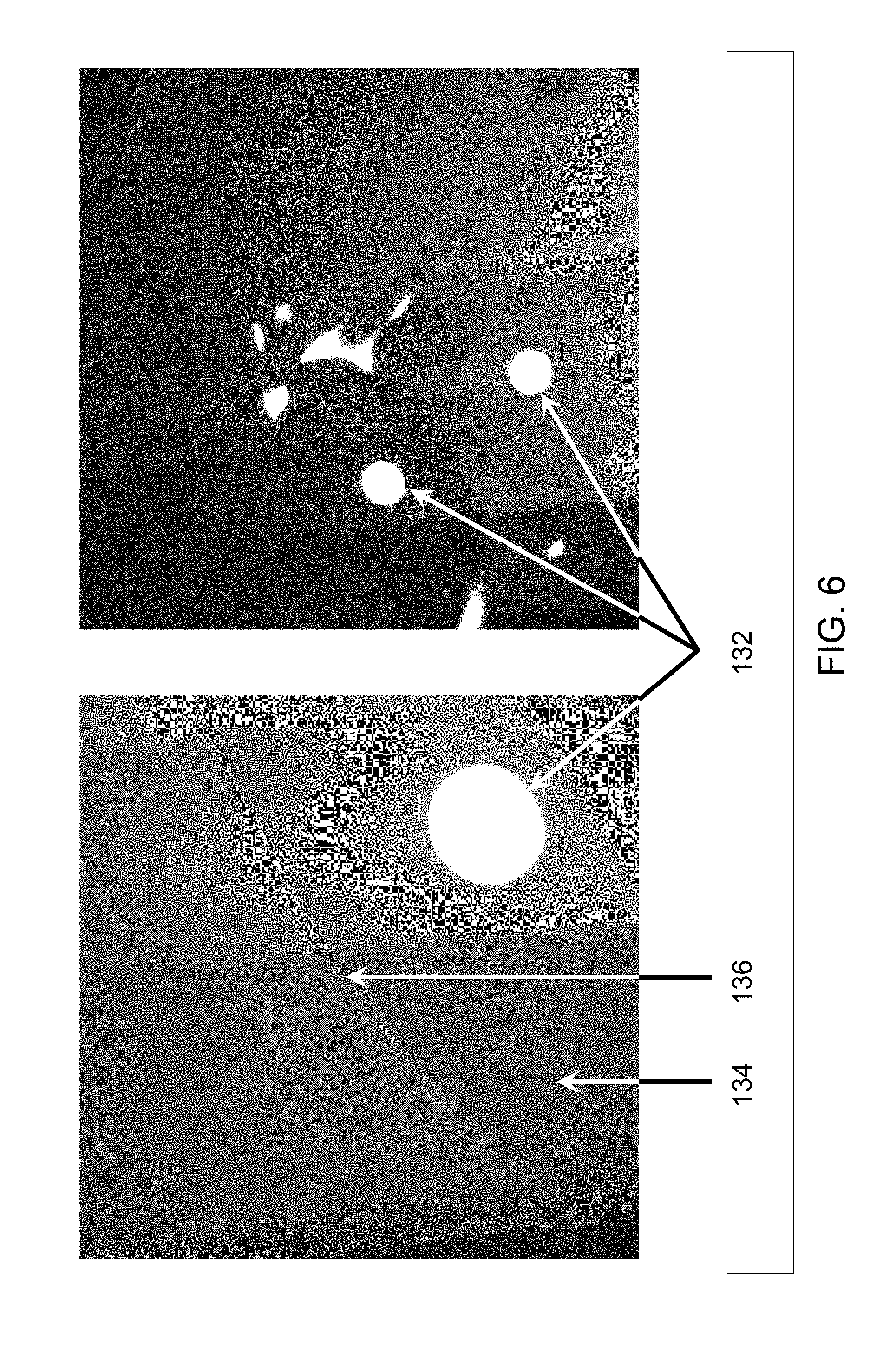
[0056] FIG. 6 illustrates a scanning electron microscopy (SEM) photomicrograph of a porous thermal barrier coating 130 formed by coating a mixture of YSZ and elemental carbon, using the APS process. The microstructure of the porous thermal barrier coating 130 as illustrated in FIG. 6 is characterized by grains 134 having a plurality of grain boundaries 136. The microstructure further includes plurality of susbtantially spherical pores 132 present inside the grains 134 (intragranular pores). The pores 132 are generated by entrapped carbon-containing gas.
[0057] Without being bound by any theory, is believed that the presence of gas-forming additive (e.g., elemental carbon) in the feedstock material may result in additional porosity, because of gases (e.g., carbon monoxide, carbon dioxide, and the like) produced from the decomposition of the gas-forming additive at high temperatures. These gases, because of being insoluble in the thermal barrier coating material, may be trapped within the thermal barrier coating material. The pressure exerted by the entrapped gas on the surrounding thermal barrier material may inhibit pore coarsening and redistribution in the microstructure, such that the thermal barrier coating retains fine porosity and the microstructure of the thermal barrier coating may be thermally stabilized. The controlled porosity may further result in lower thermal conductivity of the porous thermal barrier coating. Therefore, in some such embodiments, the porous thermal barrier coatings may provide enhanced thermal protection, because for the same coating thickness, the temperature gradient across the coating is higher. Alternatively, the turbine engine components can be designed for thinner thermal barrier coatings and, where applicable, lower cooling air flow rates. This may lead to reduction in processing and material costs, and promote component life and engine efficiency.
[0058] The foregoing examples are merely illustrative, serving to exemplify only some of the features of the disclosure. Accordingly, it is the Applicants' intention that the appended claims are not to be limited by the choice of examples utilized to illustrate features of the present disclosure. As used in the claims, the word "comprises" and its grammatical variants logically also subtend and include phrases of varying and differing extent such as for example, but not limited thereto, "consisting essentially of" and "consisting of." Where necessary, ranges have been supplied; those ranges are inclusive of all sub-ranges there between. It is to be expected that variations in these ranges will suggest themselves to a practitioner having ordinary skill in the art and where not already dedicated to the public, those variations should where possible be construed to be covered by the appended claims. It is also anticipated that advances in science and technology will make equivalents and substitutions possible that are not now contemplated by reason of the imprecision of language and these variations should also be construed where possible to be covered by the appended claims.
* * * * *
D00000
D00001
D00002
D00003
D00004
D00005
XML
uspto.report is an independent third-party trademark research tool that is not affiliated, endorsed, or sponsored by the United States Patent and Trademark Office (USPTO) or any other governmental organization. The information provided by uspto.report is based on publicly available data at the time of writing and is intended for informational purposes only.
While we strive to provide accurate and up-to-date information, we do not guarantee the accuracy, completeness, reliability, or suitability of the information displayed on this site. The use of this site is at your own risk. Any reliance you place on such information is therefore strictly at your own risk.
All official trademark data, including owner information, should be verified by visiting the official USPTO website at www.uspto.gov. This site is not intended to replace professional legal advice and should not be used as a substitute for consulting with a legal professional who is knowledgeable about trademark law.