Printable Aluminum Alloys with Good Anodized Cosmetic Surfaces
Li; Hoishun ; et al.
U.S. patent application number 16/212479 was filed with the patent office on 2019-06-06 for printable aluminum alloys with good anodized cosmetic surfaces. The applicant listed for this patent is Apple Inc.. Invention is credited to Herng-Jeng Jou, Hoishun Li, James A. Wright, James A. Yurko.
| Application Number | 20190169717 16/212479 |
| Document ID | / |
| Family ID | 66658903 |
| Filed Date | 2019-06-06 |


| United States Patent Application | 20190169717 |
| Kind Code | A1 |
| Li; Hoishun ; et al. | June 6, 2019 |
Printable Aluminum Alloys with Good Anodized Cosmetic Surfaces
Abstract
The disclosure provides aluminum alloys with high tensile strength and appealing cosmetics and improved tensile yield strength. The aluminum alloys include 0.5 to 3.0 wt % Mg and 0.2 to 3.0 wt % Si. The alloys have a weight ratio of Mg to Si ranging from 2 to 4.
| Inventors: | Li; Hoishun; (San Jose, CA) ; Yurko; James A.; (Saratoga, CA) ; Jou; Herng-Jeng; (San Jose, CA) ; Wright; James A.; (Los Gatos, CA) | ||||||||||
| Applicant: |
|
||||||||||
|---|---|---|---|---|---|---|---|---|---|---|---|
| Family ID: | 66658903 | ||||||||||
| Appl. No.: | 16/212479 | ||||||||||
| Filed: | December 6, 2018 |
Related U.S. Patent Documents
| Application Number | Filing Date | Patent Number | ||
|---|---|---|---|---|
| 62595161 | Dec 6, 2017 | |||
| Current U.S. Class: | 1/1 |
| Current CPC Class: | C22F 1/05 20130101; C22C 21/00 20130101; C22C 1/0416 20130101; C22C 1/026 20130101; C22C 32/0036 20130101; C22C 21/08 20130101; C22F 1/043 20130101; C22C 21/02 20130101; C22C 32/0078 20130101; B22F 3/1055 20130101; C22F 1/04 20130101; C22F 1/047 20130101; B33Y 70/00 20141201 |
| International Class: | C22C 21/08 20060101 C22C021/08; C22C 1/02 20060101 C22C001/02 |
Claims
1. An aluminum alloy comprising: 0.5 to 3.0 wt % Mg and 0.2 to 3.0 wt % Si, wherein the alloy has a weight ratio of Mg to Si ranging from 2.0 to 4.0.
2. The alloy of claim 1, wherein the alloy comprises 0.5 to 1.6 wt % Mg.
3. The alloy of claim 1, wherein the alloy comprises 0.2 to 0.5 wt % Si.
4. The alloy of claim 1, wherein the alloy comprises at least 0.04 wt % Fe.
5. The alloy of claim 1, wherein the alloy comprises 0.35 wt % Fe or less.
6. The alloy of claim 1, wherein the alloy comprises less than 0.06 wt % of the one or more elements Cu, Cr, Mn, Zn, and V.
7. The alloy of claim 1, wherein the alloy further comprises up to 0.5 wt % of an additional metal chosen from Zr, Sc, and any combination thereof.
8. The alloy of claim 1, wherein the alloy has a yield strength of at least 200 MPa.
9. The alloy of claim 8, wherein a Scheil temperature of the alloy is higher than a solvus temperature T.sub.solvus for Mg.sub.2Si.
10. The alloy of claim 1, wherein the alloy has a Scheil temperature .DELTA.T.sub.80%-99% smaller than 60.degree. C.
11. The alloy of claim 1, wherein the alloy has a solutionizing temperature window of at least 20.degree. C.
12. The alloy of claim 1, wherein the alloy has a critical cooling rate less than 80.degree. C./s.
13. The alloy of claim 1, wherein the alloy comprises MgSi.sub.2 particles and excess Mg in the alloy matrix in an amount of up to about 2 wt % of the alloy.
14. The alloy of claim 13, wherein the alloy has the Mg.sub.2Si particles of at least 0.15 vol. %.
15. The alloy of claim 1, wherein the alloy comprises 0.8 to 1.2 wt % Mg.sub.2Si particles and 0.6 to 0.75 wt % Mg within the Al matrix.
16. The alloy of claim 1, wherein the alloy comprises an eutectic fraction of at least 5% such that hot tearing from thermal contraction during solidification is reduced.
17. An aluminum alloy comprising 0.5 to 1.6 wt % Mg, 0.2 to 0.5 wt % Si, 0.04 to 0.35 wt % Fe, less than 0.06 wt % of the one or more elements Cu, Cr, Mn, Zn, and V, 0.5 wt % of an additional metal chosen from Zr, Sc, and any combination thereof, and the remainder aluminum and incidental impurities; wherein the weight ratio of Mg to Si ranges from 3.0 to 4.0.
18. The aluminum alloy of claim 17, comprising 0.8 to 1.2 wt % Mg.sub.2Si particles and 0.6 to 0.75 wt % Mg.
19. The aluminum alloy of claim 18, wherein the Mg.sub.2Si particles are at least 0.15 vol % of the alloy.
20. A method of making an aluminum alloy comprising: depositing a powdered aluminum alloy comprising 0.5 to 3.0 wt % Mg and 0.2 to 3.0 wt % Si, wherein the alloy has a weight ratio of Mg to Si ranging from 2.0 to 4.0 on an aluminum alloy substrate; heating the powdered aluminum alloy to form a melted alloy on the aluminum alloy substrate; and cooling the melted alloy on the aluminum alloy substrate to form the aluminum alloy.
Description
CROSS-REFERENCE TO RELATED PATENT APPLICATION
[0001] This patent application claims the benefit under 35 U.S.C. .sctn. 119(e) of U.S. Patent Application Ser. No. 62/595,161, entitled "Printable Aluminum Alloys with Good Anodized Cosmetic Surfaces," filed on Dec. 6, 2017, which is incorporated herein by reference in its entirety.
TECHNICAL FIELD
[0002] The disclosure generally relates to aluminum alloys. More specifically, the embodiments relate to aluminum alloys with high tensile strength and cosmetically appealing anodized surfaces that can be used in additive manufacturing for applications including use as enclosures for electronic devices.
BACKGROUND
[0003] Commercial aluminum (Al) alloys have been used for making enclosures for electronic devices, including mobile phones, tablet computers, notebook computers, instrument windows, appliance screens, and the like. The enclosures may be machined or additive manufactured from the aluminum alloys. Generally, additive manufacturing is a lower cost process than machining processes, such as computer numerical control (CNC). The commercial aluminum alloys do not have a neutral color, but rather the anodized surface is either dark or yellowish.
[0004] Aluminum alloys, such as commercial aluminum alloys, such as A356 and A383, include high silicon (Si) content, which is typically greater than 2.0 wt %. For example, the aluminum (Al) alloy A356 includes 0.3 wt % magnesium (Mg) and 7% wt % (Si), while Al alloy A383 includes 3.5 wt % copper (Cu), 8.5 wt % Si, and 3 wt % zinc (Zn). The high Si content in the processed alloys provides good fluidity for the alloys for additive manufacturing, and also hot cracking resistance. However, such high silicon contents lead to formation of silicon particles and other particles such as AlFeSi- . The silicon particles are non-conductive and are not anodized, therefore reducing the net amount the entire alloy is anodized. As a result, the commercial Al alloys, such as A356 and A383, create dull, grey, unappealing surfaces when anodized.
[0005] In some other cases, low silicon heat treatable aluminum alloys, such as commercial Al alloy 6063, can form an appealing anodized surface finish and have a relatively high yield strength of about 220 MPa. However, commercial Al alloys 6063 have low fluidity and propensity to crack during solidification and are not suitable for additive manufacturing.
[0006] Although the Al alloys use high Si or Mn to help processability, Si or Mn affects the brightness and/or color of the anodized finish. There still remains a need to develop aluminum alloys with appealing cosmetics and improved tensile yield strength.
BRIEF SUMMARY
[0007] Embodiments described herein may provide aluminum alloys with appealing cosmetics and improved tensile yield strength.
[0008] In one embodiment, an aluminum alloy includes 0.5 to 3.0 wt % Mg and 0.2 to 3.0 wt % Si, where the alloy has a weight ratio of Mg to Si ranging from 2 to 4.
[0009] Additional embodiments and features are set forth in part in the description that follows, and will become apparent to those skilled in the art upon examination of the specification or may be learned by the practice of the embodiments discussed herein. A further understanding of the nature and advantages of certain embodiments may be realized by reference to the remaining portions of the specification and the drawings, which form part of this disclosure.
BRIEF DESCRIPTION OF THE DRAWINGS
[0010] The following figures are provided to disclose non-limiting aspects of the disclosure.
[0011] FIG. 1 depicts a predicted solidification diagram for various alloys in accordance with embodiments of the disclosure.
[0012] FIG. 2A depicts an example Mg--Si composition space with Mg up to 2 wt % for compositions having various solidification temperature ranges for Example Alloy 1 containing 0.08 wt % Fe in accordance with embodiments of the disclosure.
[0013] FIG. 2B depicts an example Mg--Si composition space with Mg up to 2 wt % for compositions having various solutionizing temperature ranges for Example Alloy 1 containing 0.08 wt % Fe in accordance with embodiments of the disclosure.
[0014] FIG. 2C depicts an example Mg--Si composition space with Mg up to 2 wt % for compositions having various critical cooling rates for Example Alloy 1 containing 0.08 wt % Fe in accordance with embodiments of the disclosure.
[0015] FIG. 2D depicts an overlapping composition space of Mg and Si among Scheil .DELTA.T.sub.80%-99% solutionizing temperature window and critical cooling rate for Example alloy 1 containing 0.08 wt % Fe in accordance with embodiments of the disclosure.
[0016] FIG. 3A depicts an example Mg--Si composition space with Mg up to 3 wt % for compositions having various Scheil temperatures and solvus temperatures in accordance with embodiments of the disclosure.
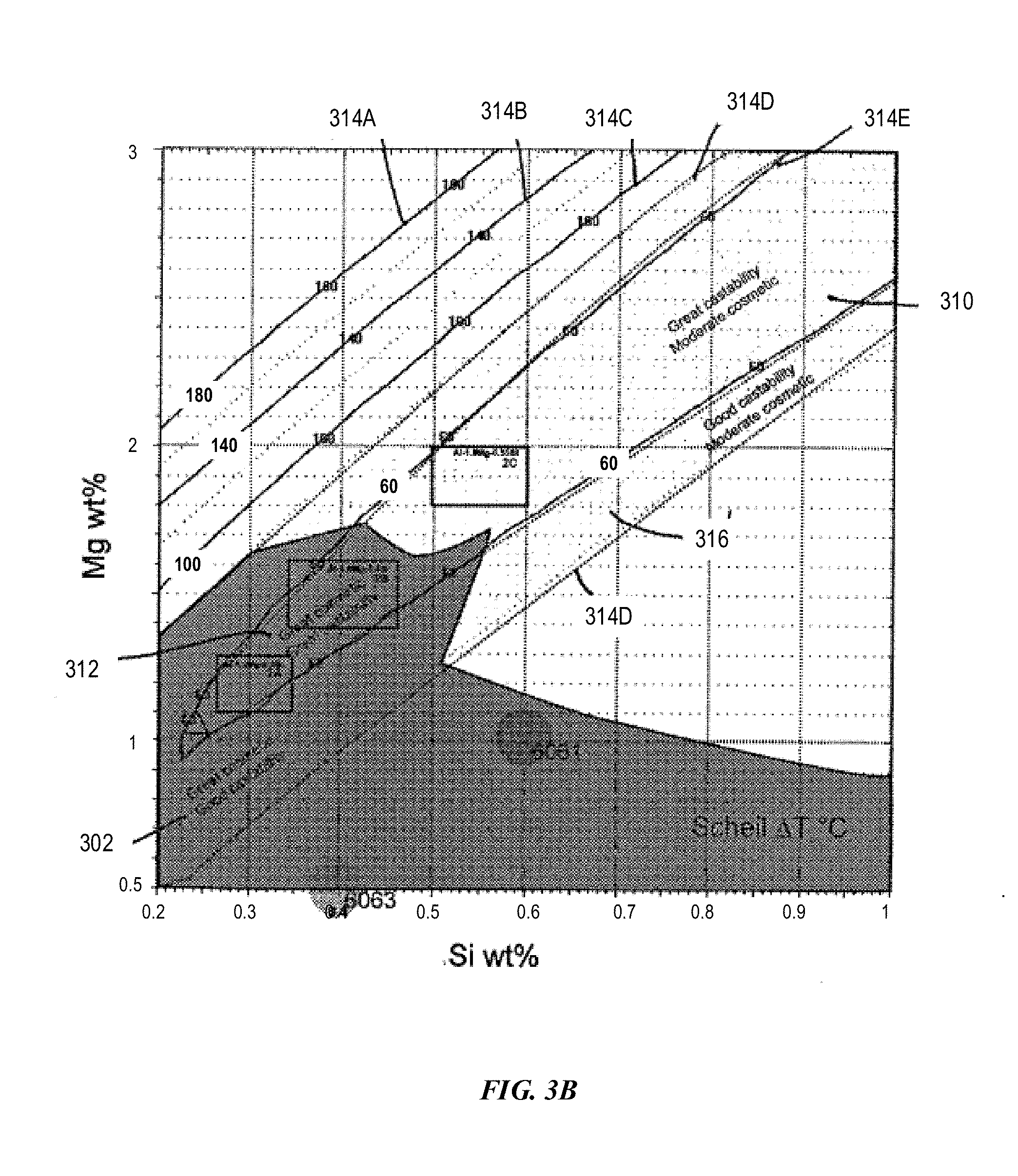
[0017] FIG. 3B depicts an example Mg--Si composition space with Mg up to 3 wt % for compositions having various solidification temperature ranges in accordance with embodiments of the disclosure.
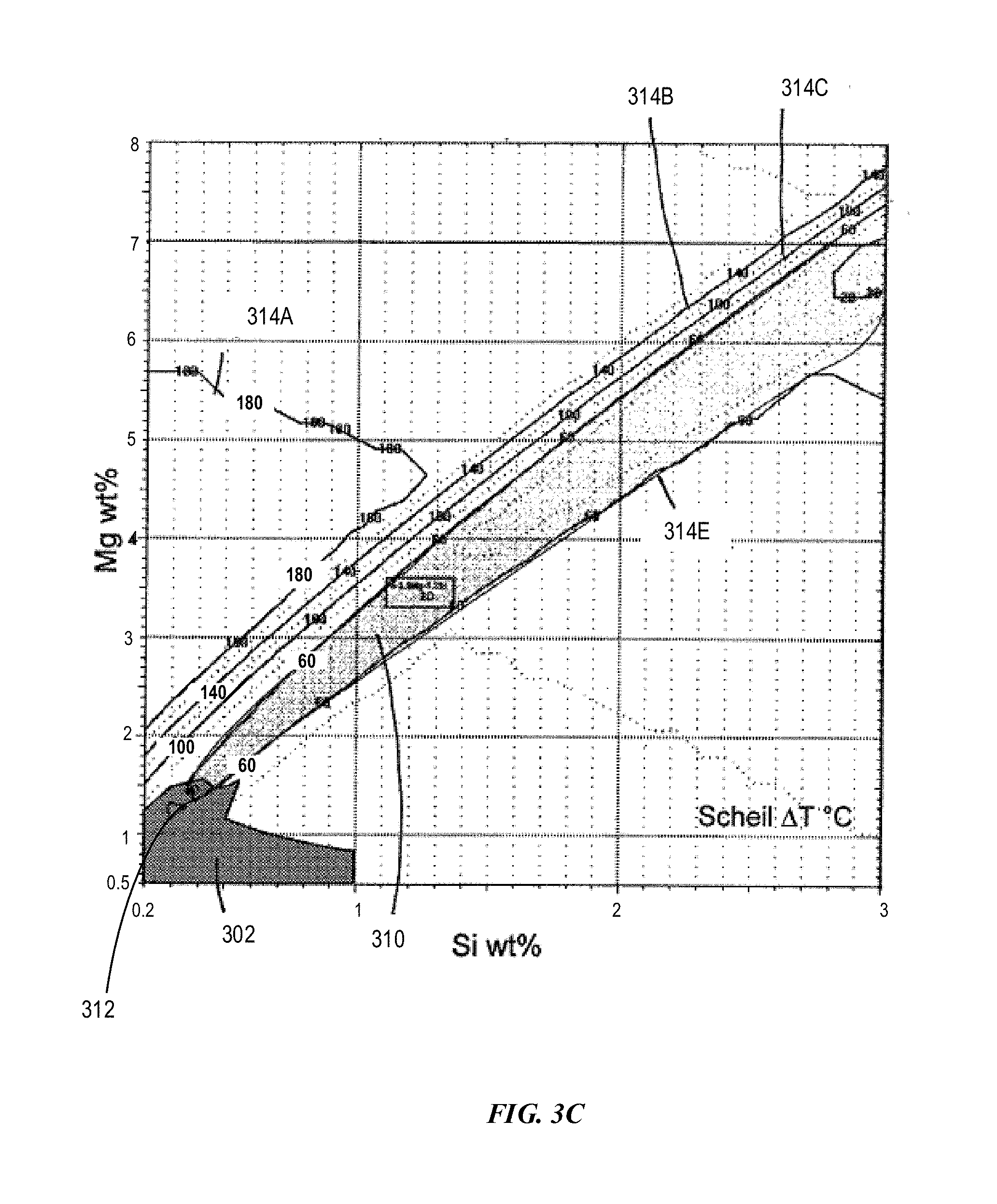
[0018] FIG. 3C depicts an example Mg--Si composition space with Mg up to 8 wt % for compositions having various solidification temperature ranges in accordance with embodiments of the disclosure.
[0019] FIG. 4 depicts an example Mg--Si composition space with Mg up to 2 wt % for compositions having various tensile strengths for Example Alloy 1 containing 0.08 wt % Fe in accordance with embodiments of the disclosure.
[0020] FIG. 5 depicts an example Mg--Si composition space with Mg up to 2 wt % for compositions having various Mg.sub.2Si secondary phase for Example Alloy 1 containing 0.08 wt % Fe in accordance with embodiments of the disclosure.
[0021] FIG. 6 depicts an example Fe vs. impurity (including Cu, Mn, Cr, Zn, and or V) composition space with Fe up to 0.25 wt % and impurity up to 0.1% for an Example Alloy having various Mg.sub.2Si secondary phases in accordance with embodiments of the disclosure.
[0022] FIG. 7A depicts an example of a mold cavity in accordance with embodiments of the disclosure.
[0023] FIG. 7B depicts an example of a partial mold filling following FIG. 7A in accordance with embodiments of the disclosure.
[0024] FIG. 7C depicts an example of a complete mold filling following FIG. 7B in accordance with embodiments of the disclosure.
[0025] FIG. 7D depicts an example of partial solidification following FIG. 7C in accordance with embodiments of the disclosure.
[0026] FIG. 7E depicts an example of complete solidification following FIG. 7D in accordance with embodiments of the disclosure.
[0027] FIG. 7F depicts an example of the alloy in the mold cavity without any hot tearing following FIG. 7E in accordance with embodiments of the disclosure.
[0028] FIG. 7G depicts an example of the alloy in the mold cavity with hot tearing in the middle of the thin portion following FIG. 7E in accordance with embodiments of the disclosure.
[0029] FIGS. 8A-8B depict an example of the middle portion of an H-shape mold cavity (also referred as a "finger") with varying thicknesses, FIG. 8A depicts a thinner mold cavity, and FIG. 8B depicts a thicker mold cavity, in accordance with embodiments of the disclosure.
DETAILED DESCRIPTION
[0030] The disclosure may be understood by reference to the following detailed description, taken in conjunction with the drawings as described herein. It is noted that, for purposes of illustrative clarity, certain elements in various drawings may not be drawn to scale, may be represented schematically or conceptually, or otherwise may not correspond exactly to certain physical configurations of embodiments.
[0031] The disclosure is directed aluminum alloys that have a combination of good processability (e.g. for additive manufacturing and/or non-iron mold casting methods), cosmetically appealing anodized finish, a yield strength of at least 200 MPa, and/or corrosion resistance. These alloys combine the good processability characteristics of commercially processable Al alloys with the cosmetically appealing smooth anodizable surface finish of commercial wrought aluminum alloys.
[0032] In some aspects, the aluminum alloys have a weight ratio of Mg to Si ranging from 2.0 to 4.0 for high strength alloys. The ratio of Mg to Si may be selected to have a small solidification temperature range (e.g. Scheil .DELTA.T.sub.80%-99% less than 60.degree. C.) such that the alloys may be suitable for the additive manufacturing. The ratio of Mg to Si may also be selected such that the Mg.sub.2Si particle volume % is equal to or greater than 0.15 volume % such that the alloys may be in the desired Mg--Si composition space and have the strength. The ratio of Mg to Si may further be selected for good cosmetic appeal. In some variations, the alloys can have reduced silicon (Si), for example, ranging from 0.2 wt % to 3.0 wt %.
[0033] In some variations, the alloys can have Mg.sub.2Si+AlFeSi+secondary phases less than or equal to 2 wt % of the alloy. In some variations, the alloys can have Mg.sub.2Si+AlFeSi+secondary phases less than or equal to 1.5 wt % of the alloy. In some variations, the alloys can have Mg.sub.2Si+AlFeSi+secondary phases less than or equal to 1.0 wt % of the alloy. In some variations, the alloy can have not more than 1.5 vol % Mg.sub.2Si, not more than 1 vol % AlFeSi, and/or not more than 0.5 vol % other secondary phases. In some additional variations, the alloy can have not more than 4.0 vol % Mg.sub.2Si+AlFeSi+secondary phases.
[0034] In some variations, the alloy can have not more than 1.5 vol % Mg.sub.2Si. In some variations, the alloy can have not more than 1.0 vol % Mg.sub.2Si. In some variations, the alloy can have not more than 0.5 vol % Mg.sub.2Si. In some variations, the alloy can have not more than 1 vol % AlFeSi. In some variations, the alloy can have not more than 0.8 vol % AlFeSi. In some variations, the alloy can have not more than 0.6 vol % AlFeSi. In some variations, the alloy can have not more than 0.4 vol % AlFeSi. In some variations, the alloy can have not more than 0.5% other secondary phases. In some variations, the alloy can have not more than 0.4% other secondary phases. In some variations, the alloy can have not more than 0.3% other secondary phases. In some variations, the alloy can have not more than 0.2% other secondary phases. In some additional variations, the alloy can have not more than 4 vol % Mg.sub.2Si+AlFeSi+secondary phases. In some additional variations, the alloy can have not more than 4.0 vol % Mg.sub.2Si+AlFeSi+secondary phases. In some additional variations, the alloy can have not more than 3.5 vol % Mg.sub.2Si+AlFeSi+secondary phases. In some additional variations, the alloy can have not more than 3.0 vol % Mg.sub.2Si+AlFeSi+secondary phases. In some additional variations, the alloy can have not more than 2.5 vol % Mg.sub.2Si+AlFeSi+secondary phases. In some additional variations, the alloy can have not more than 2.0 vol % Mg.sub.2Si+AlFeSi+secondary phases. In some additional variations, the alloy can have not more than 1.5 vol % Mg.sub.2Si+AlFeSi+secondary phases. In some additional variations, the alloy can have not more than 1.0 vol % Mg.sub.2Si+AlFeSi+secondary phases.
[0035] To maintain cosmetic appeal, the alloys may have Fe less than 0.35 wt %, or 0.15 wt %, e.g. a range from 0.04 wt % to 0.35 wt % or 0.04 wt % to 0.15 wt %, and the total of elements Cu, Mn, Zn, Cr, and/or V may be less than 0.06 wt %.
[0036] In some variations, the alloys may have less than or equal to 0.35 wt % Fe. In some variations, the alloys may have less than or equal to 0.30 wt % Fe. In some variations, the alloys may have less than or equal to 0.25 wt % Fe. In some variations, the alloys may have less than or equal to 0.20 wt % Fe. In some variations, the alloys may have less than or equal to 0.15 wt % Fe. In some variations, the alloys may have less than or equal to 0.10 wt % Fe. In some variations, the alloys may have less than or equal to 0.09 wt % Fe. In some variations, the alloys may have less than or equal to 0.08 wt % Fe. In some variations, the alloys may have less than or equal to 0.06 wt % Fe. Further, in some variations, the alloys can have at least 0.02 wt % Fe. In some variations, the alloys can have at least 0.04 wt % Fe. In some variations, the alloys can have at least 0.06 wt % Fe.
[0037] In some variations, the total of elements Cu, Mn, Zn, Cr, and/or V may be less than 0.15 wt %. In some variations, the total of elements Cu, Mn, Zn, Cr, and/or V may be less than 0.10 wt %. In some variations, the total of elements Cu, Mn, Zn, Cr, and/or V may be less than 0.08 wt %. In some variations, the total of elements Cu, Mn, Zn, Cr, and/or V may be less than 0.06 wt %. In some variations, the total of elements Cu, Mn, Zn, Cr, and/or V may be less than 0.04 wt %.
[0038] In various aspects, aluminum alloys described herein can include a small amount of incidental impurities. The impurity elements can be can be present, for example, as a byproduct of processing and manufacturing. In various embodiments, an incidental impurity can be no greater than 0.05 wt % of any one additional element (i.e., a single impurity), and no greater than 0.10 wt % total of all additional elements (i.e., total impurities).
[0039] I. Solidification
A. Solidification Temperature Range (.DELTA.T.sub.80%-99%)
[0040] The present aluminum alloys are processable when the solidification temperature range (.DELTA.T.sub.80%-99%) is small. The solidification temperature range is the temperature difference between the solidus temperature and the Scheil temperature. In some embodiments, the solidus temperature range can be .DELTA.T.sub.80%-99%, where .DELTA.T.sub.80%-99% is the difference between the temperature T.sub.99%, at which at least 99% of the alloy is solidified, and the temperature T.sub.80%, at which at least 80% of the alloy is solidified. In some variations, the Scheil .DELTA.T.sub.80%-99% is less than 60.degree. C. In some variations, the Scheil .DELTA.T.sub.80%-99% is less than 50.degree. C. In some variations, the Scheil .DELTA.T.sub.80%-99% is less than 40.degree. C.
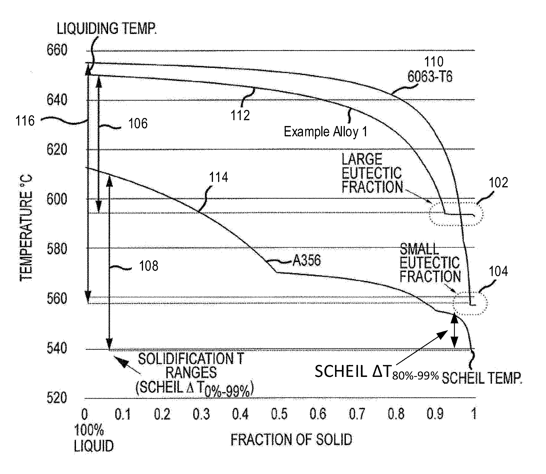
[0041] FIG. 1 depicts a predicted solidification diagram for various alloys in accordance with the embodiments of the disclosure. The prediction is obtained from a thermodynamic modeling based on the CALPHAD (CALculation of PHAse Diagrams) method, a branch of computational thermodynamics. In one embodiment, CALPHAD method takes in readily available binary phase diagrams (e.g. Al--Mg, Al--Si, Mg--Si, Al--Fe, Fe--Si) and multi-component phase diagram (e.g. Al--Mg--Si--Fe) to make prediction that is difficult to obtain experimentally. This method enables computational prediction of material properties such as solidification behavior.
[0042] As shown in FIG. 1, the solidification diagram includes a horizontal axis representing the fraction of solids formed. The solidification diagram also includes a vertical axis representing temperature starting from liquidus temperature, at which the alloy is in a liquid state, and ending at a solidus temperature or Scheil temperature, at which the alloy is fully solidified. The liquidus temperature is the equilibrium temperature above which the alloy is completely liquid. The Scheil temperature is a non-equilibrium solidus temperature, based on the Scheil approximation, at which the alloy is predicted to completely solidify. The difference between the Scheil temperature (non-equilibrium) and the solidus temperature (equilibrium temperature) is referred to a solidification temperature range, which is a processing window for solution heat treatment in the completely solid state. Lower solidification temperature range is more desirable for better processability.
[0043] Solidification curves 110, 112, and 114 represent commercial alloy 6063-T6, present Example Alloy 1, and commercial Al alloy A356, respectively. Each solidification curve shows a solidus temperature (equilibrium) versus fraction of solid from 0 to 1.0. Turning to curve 110 representing commercial alloy 6063-T6, curve 110 starts from a liquid state at about 655.degree. C., and solidifies in a small eutectic fraction region 104 at a solidus temperature of about 557.degree. C. (also referred to a Scheil temperature).
[0044] In some embodiments, the solidification temperature range can be .DELTA.T.sub.80%-99%, where .DELTA.T.sub.80%-99% is defined as the temperature T.sub.80%, at which at least 80% of the alloy is solidified, subtracted by the temperature T.sub.99%, at which at least 99% of the alloy is solidified. In some embodiments, the alloy 6063-T6 has a solidification temperature range 116 which can be represented by Scheil .DELTA..sub.0%-99% (the difference between the liquidus temperature and the Scheil temperature).
[0045] Turning to solidification curve 112 representing Example Alloy 1, Example Alloy 1 starts at a liquidus temperature of about 650.degree. C. and solidifies in a large eutectic fraction region 102 at a Scheil temperature of about 593.degree. C. Example Alloy 1 has a solidification temperature range 106 much smaller than that of the commercial alloy 6063-T6.
[0046] Turning to curve 114 representing commercial alloy A356, the alloy A356 starts at a liquidus temperature of about 615.degree. C., and becomes solid at a Scheil temperature or solidus temperature of about 538.degree. C. The solidification temperature range 108 of commercial alloy A356 is lower than that of commercial alloy 6063-T6. Further, commercial alloy A356 does not have any eutectic fraction region like eutectic fraction region 102 for Example Alloy 1 or an eutectic fraction region 104 the alloy 6063-T6.
[0047] Based on the solidification diagram as shown in FIG. 1, liquidus temperatures, Scheil temperatures, and solidification temperature ranges are provided for various alloys, and are listed in Table 1. Table 1 also lists the alloy compositions, solvus temperatures, and tensile yield strengths for various alloys. The solvus temperature is the temperature at which all solid precipitates (e.g. Mg.sub.2Si) dissolve into aluminum. Yield strengths of the alloys may be determined per ASTM E8, which covers the testing apparatus, test specimens, and testing procedure for tensile testing.
TABLE-US-00001 TABLE 1 Composition and Properties of Processable Aluminum Alloys in Comparison to Commercial Aluminum Alloys Yield Liquidus Scheil Scheil Solvus Strength Alloy Mg Si Cu Fe T (.degree. C.) T (.degree. C.) .DELTA.T.sub.80%-99% T (.degree. C.) MPa A356-T6 0.3 7 0.2 0.2 615 538 24 >538 165 6063-T6 0.55 0.4 0 0.12 655 557 83 490 220 Example 1.5 0.44 0 0.08 650 593 33 580 >200 Alloy 1 Example 1.3 0.35 0 0.08 652 593 38 555 >200 Alloy 2 Example 1.3 0.35 0.1 0.08 652 581 49 557 >200 Alloy 3 Example 1.1 0.3 0 0.08 653 594 42 538 >200 Alloy 4
[0048] As shown in Table 1, Example Alloys 1-4 include higher Mg content than commercial alloys A356 and 6063, and also lower Si content than commercial Al alloy A356. The Al alloy may also include a trace of copper (Cu), such as 0.1 wt % for Example Alloy 3.
[0049] The solidification temperature ranges of the present Al alloys are comparable to that of the commercial Al alloy but significantly lower than that of alloy 6063-T6. The Al alloys can be processable or capable for additive manufacturing based on their small solidification temperature ranges.
[0050] In some variations, the Al alloys also have low Scheil .DELTA.T.sub.80%-99%, which can be comparable to that of commercial alloy A356. Commercial Al alloy A356-T6 has a Scheil .DELTA.T.sub.80%-99% of 24.degree. C., which is significantly smaller than that of commercial Al alloy 6063-T6 (e.g. 83.degree. C.). For example, Example Alloys 1-4 have .DELTA.T.sub.80%-99% of 33.degree. C., 38.degree. C., 49.degree. C., and 42.degree. C., respectively, which are comparable to that of commercial Al alloy A356-T6. When .DELTA.T.sub.80%-99% is less than 60.degree. C., the present Al alloys are suitable for additive manufacturing.
[0051] Scheil .DELTA.T.sub.80%-99% is better than Scheil .DELTA.T.sub.0%-99%, because .DELTA.T.sub.80%-99% is consistently small for the present alloys including Example Alloys 1-4. However, .DELTA.T.sub.0%-99% was found to vary largely with Example Alloys 1-4. Example Alloys 1-4 have .DELTA.T.sub.80%-99% within 50.degree. C., as shown in Table 1.
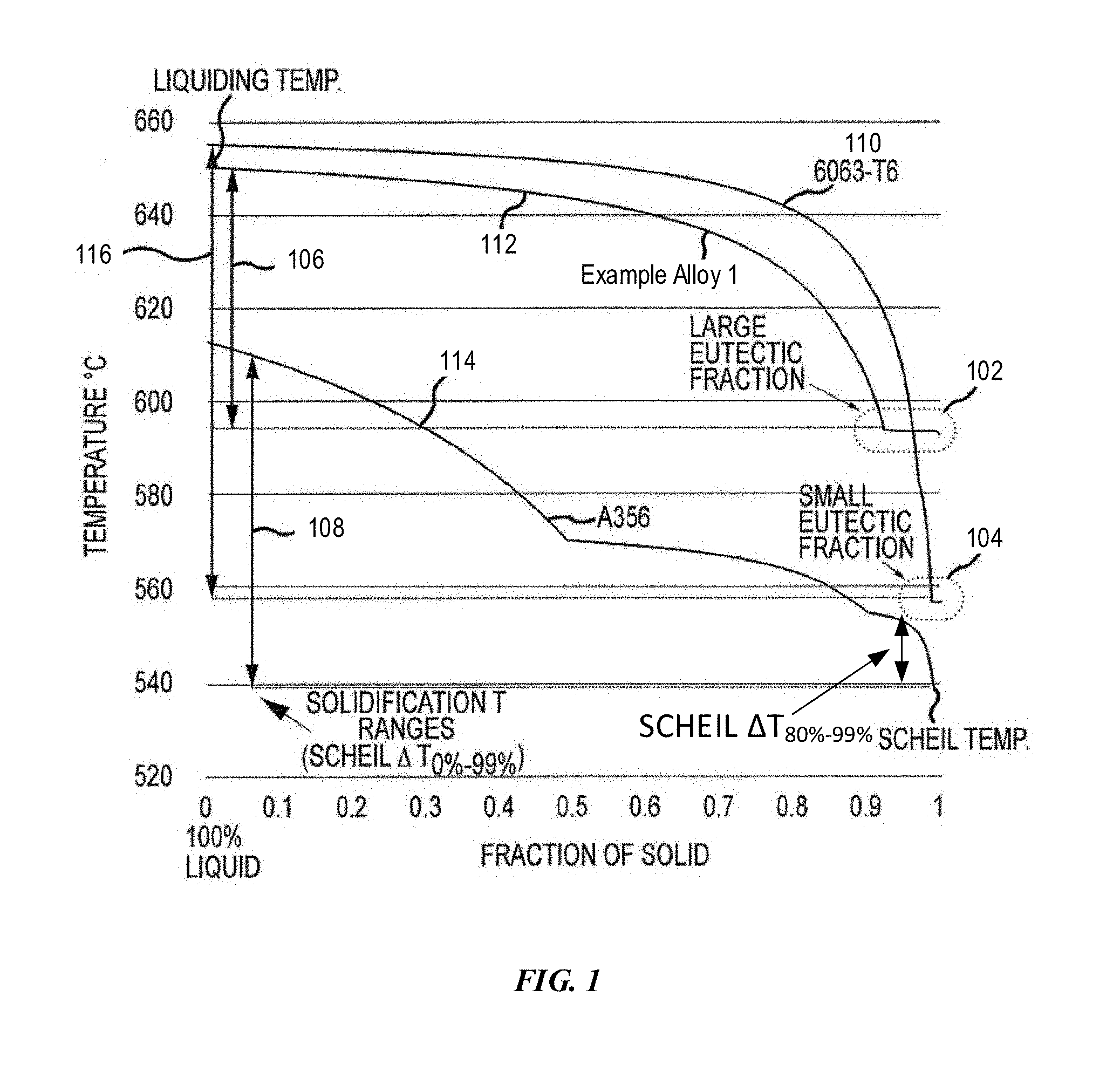
[0052] FIG. 2A depicts an example Mg--Si composition space with Mg from 0.5 wt % to 2 wt % for compositions having various solidification temperature ranges for Example Alloy 1 containing 0.08 wt % Fe in accordance with embodiments of the disclosure. As shown, within composition space for Mg from 0.5 wt % to 2 wt % and Si from 0.2 wt % to 1 wt %, curves 204 have various constant Scheil .DELTA.T.sub.80%-99% ranges including 40.degree. C., 60.degree. C., 80.degree. C., and 120.degree. C.
[0053] In some variations, the Mg--Si composition space 202 has a ratio of Mg to Si ranging from 2.0 to 4.0. In some variations, the Mg--Si composition space 202 has a ratio of Mg to Si ranging from 3.0 to 4.0. Turning to curve 204, when the Scheil .DELTA.T.sub.80%-99% range is 40.degree. C., curve 204 has a portion within the Mg--Si composition space 202. When the .DELTA.T.sub.80%-99% range increases from 40.degree. C. to 60.degree. C., the portion of curve 204 completely shifts outside the composition space 202. When the Scheil .DELTA.T.sub.80%-99% range further increases to 80.degree. C. or 120.degree. C., curve 204 does not have any overlap with the composition space 202. Also, Example Alloy 1 (labeled as 226) and Example Alloy 4 (labeled as 224) are within the composition space 202, while 6063 alloys (labeled as 220 and 222) are outside the composition space 202. As such, the Scheil .DELTA.T.sub.80%-99% should be less than 60.degree. C. for the present alloys to be processable or to be able for additive manufacturing.
B. Solutionizing Temperature Window
[0054] In some variations, the Mg--Si composition may also be limited by a solutionizing temperature window or solutionizing window, which can be the difference between 1/2(T.sub.99%solid+T.sub.eq.solidus) and the solvus temperature T.sub.solvus for Mg.sub.2Si. The solvus temperature is the temperature at which all solid precipitates (e.g. Mg.sub.2Si) dissolve into aluminum. For the Al alloys to be suitable for additive manufacturing, such as 3D printing, the Al alloys need to have the solutionizing temperature window greater than 20.degree. C.
[0055] FIG. 2B depicts an example Mg--Si composition space with Mg from 0.5 wt % to 2 wt % for compositions having various solutionizing temperature ranges for Example Alloy 1 containing 0.08 wt % Fe in accordance with embodiments of the disclosure. As shown, within composition space for Mg from 0.5 wt % to 2 wt % and Si from 0.2 wt % to 1 wt %, curves 206 have various constant solutionizing temperature ranges including 0.degree. C., 20.degree. C., 40.degree. C., 60.degree. C., 80.degree. C., and 100.degree. C. When the solutionizing temperature range increases, curve 206 shifts down toward the bottom left corner such that both Mg and Si decreases. Also, Example Alloys 1 and 4 are within the composition space 202, while 6063 alloys are outside the composition space 202. When the solutionizing temperature range is 20.degree. C. or higher, curves 206 have overlapping with composition space 202. As such, the solutionizing temperature window is at least 20.degree. C.
C. Critical Cooling Rate
[0056] The Al alloys can be cooled slowly enough to suppress Mg.sub.2Si precipitation from quenching at a critical cooling rate. The rates for quenching the Al alloys should be lower than the critical cooling rate to suppress the Mg.sub.2Si precipitation. As an example, the critical cooling rate for Mg.sub.2Si for Example Alloy 1 is determined to be 82.degree. C./s, and T.sub.solvus, for dissolving Mg.sub.2Si particles is determined to be 580.degree. C.
[0057] FIG. 2C depicts an example Mg--Si composition space with Mg from 0.5 wt % to 2 wt % for compositions having various critical cooling rates for Example Alloy 1 containing 0.08 wt % Fe in accordance with embodiments of the disclosure. As shown, within composition space for Mg from 0.5 wt % to 2 wt % and Si from 0.2 wt % to 1 wt %, curves 208 have various constant critical cooling rates including 3.degree. C./s, 10.degree. C./s, 20.degree. C./s, 40.degree. C./s, 60.degree. C./s, and 80.degree. C./s. When the critical cooling rate increases, curve 208 shifts up toward the upper right corner such that both Mg and Si increase. Also, Example Alloys 1 and 4 are within the composition space 202, while 6063 alloys are outside the composition space 202.
[0058] FIG. 2D depicts an overlapping composition space of Mg and Si among Scheil .DELTA.T.sub.80%-99%, the solutionizing temperature window, and critical cooling rate for Example Alloy 1 containing 0.08 wt % Fe in accordance with embodiments of the disclosure. Example Alloy 1 does not include any impurity, such as Cu, Mn, Cr, Zn, or V, among others.
[0059] As shown in FIG. 2D, inside a first composition space 210 having a first contour line 210A, the Scheil .DELTA.T.sub.80%-99% is less than 60.degree. C. Also, inside a second composition space 212 having a second contour line 212A, the solutionizing temperature window is greater than 20.degree. C. Further, inside a third composition space 214 having a third contour line 214A, the critical cooling rate is less than 80.degree. C./s. An overlapping composition space 216 for the first, second, and third composition space 210, 212, and 214 can meet all three requirements including (1) Scheil .DELTA.T.sub.80%-99% less than 60.degree. C., (2) solutionizing temperature window greater than 20.degree. C., and (3) a critical cooling rate less than 80.degree. C./s. The overlapping composition space has Mg up to about 1.6 and Si up to 0.5.
[0060] In some embodiments, the Al alloy may include 0.5 wt % to 1.6 wt % Mg. In some embodiments, the Al alloy may include 0.2 wt % to 0.5 wt % Si.
[0061] In some embodiments, the Al alloy may include equal to or less than 1.6 wt % Mg. In some embodiments, the Al alloy may include equal to or less than 1.4 wt % Mg. In some embodiments, the Al alloy may include equal to or less than 1.2 wt % Mg. In some embodiments, the Al alloy may include equal to or less than 1.0 wt % Mg. In some embodiments, the Al alloy may include equal to or less than 0.8 wt % Mg. In some embodiments, the Al alloy may include equal to or less than 0.6 wt % Mg. In some embodiments, the Al alloy may include at least 0.5 wt % Mg. In some embodiments, the Al alloy may include at least 0.7 wt % Mg. In some embodiments, the Al alloy may include at least 0.9 wt % Mg. In some embodiments, the Al alloy may include at least 1.1 wt % Mg. In some embodiments, the Al alloy may include at least 1.3 wt % Mg. In some embodiments, the Al alloy may include at least 1.5 wt % Mg.
[0062] In some embodiments, the Al alloy may include equal to or less than 0.5 wt % Si. In some embodiments, the Al alloy may include equal to or less than 0.4 wt % Si. In some embodiments, the Al alloy may include at least 0.2 wt % Si. In some embodiments, the Al alloy may include at least 0.3 wt % Si. In some embodiments, the Al alloy may include at least 0.4 wt % Si.
D. Large Eutectic Fraction Region
[0063] In various aspects, the alloys have large eutectic fraction regions. The eutectic fraction is a fraction range of solid formed at a constant temperature. In various aspects, the alloys are not susceptible to hot tearing because the alloys have a large eutectic fraction, e.g. the alloy has a large fraction of liquid to solidify into solid at a constant temperature. In eutectic fraction regions 102 or 104, liquid solidifies into solid at a constant temperature such that no contraction can be induced from any temperature change and the contraction is only induced by transformation from liquid to solid.
[0064] However, commercial alloy A356 does not have the same kind of eutectic region as Example Alloy 1. The eutectic fraction/region of commercial alloy A356 starts to form at about 90% solid, but it tapers down after that the eutectic fraction/region. Alloy A356 does not hot crack, because silicon has a higher molar volume than aluminum when silicon comes out from the liquid so the newly formed silicon actually expands and helps counter the thermal stress that causes hot cracking.
[0065] In various aspects, the alloys can have a large eutectic fraction region to reduce or prevent likelihood of hot tearing. Unlike commercial alloy 6063, which has a very small eutectic fraction region (an eutectic fraction of about 1-2%), Example Alloy 1 has a large eutectic fraction region (an eutectic fraction of about 10%).
[0066] In some aspects, the alloys can have a eutectic fraction of at least 5%. In some embodiments, the alloys can have an eutectic fraction of at least 6%. In some embodiments, the alloys can have an eutectic fraction of at least 7%. In some embodiments, the alloys can have an eutectic fraction of at least 8%. In some embodiments, the alloys can have an eutectic fraction of at least 9%. In some embodiments, the alloys can have an eutectic fraction of at least 10%.
E. Scheil Temperature Greater than T.sub.solvus for Mg.sub.2Si
[0067] In some variations, Mg may have an upper limit determined by the solvus temperature that does not exceed the Scheil temperature. Referring again to Table 1, the solvus temperature increases from 1.1 wt % to 1.5 wt % as the Mg content increased from 538.degree. C. to 580.degree. C. The solvus temperature may continue to increase with Mg content until the solvus temperature equals to the Scheil temperature for the alloy.
[0068] The Mg.sub.2Si particles can be dissolved to leave a more homogeneous structure, which is more suitable for anodizing.
[0069] Homogenization or solution treatment may be used to achieve a homogeneous structure, which helps obtain a better anodized surface finish. The heat treatment dissolves Mg.sub.2Si particles, which requires that the solvus temperature is lower than the Scheil temperature. The maximum Mg content may be limited by the heat treatment of the alloy. Without wishing to be limited to a mechanism or mode of action, the Mg can form an eutectic fraction with the aluminum matrix and Mg.sub.2Si is dissolved completely in the aluminum matrix.
[0070] Commercial alloys A356 and A383 are more easily processed (e.g., by additive manufacturing), mainly due to their high Si content. However, when commercial alloy A356 has silicon solvus temperature (.about.570.degree. C.) and Mg.sub.2Si solvus temperature (.about.557.degree. C.) greater than the Scheil temperature, the alloy cannot be heat treated to form a homogeneous structure.
In some embodiments, the alloy may include an overall amount Mg ranging from 1.0 wt % to 3.0 wt %. In some embodiments, the alloy may include Mg less than 3.0 wt %. In some embodiments, the alloy may include Mg less than 2.5 wt %. In some embodiments, the alloy may include Mg less than 2.0 wt %. In some embodiments, the alloy may include Mg less than 1.5 wt %. In some embodiments, the alloy includes Mg greater than 1.0 wt %. In some embodiments, the alloy includes Mg greater than 1.5 wt %. In some embodiments, the alloy includes Mg greater than 2.0 wt %. In some embodiments, the alloy includes Mg greater than 2.5 wt %.
[0071] II. High Tensile Strength-Mg.sub.2Si Particles
[0072] Mg.sub.2Si particles or precipitates can strengthen the alloy. Mg.sub.2Si particles or precipitates can be formed and distributed in the aluminum to strengthen the alloy. The excess Mg not incorporated into the Mg.sub.2Si particles or precipitates can be distributed in the Al matrix to further strengthen the alloy.
[0073] In various embodiments, the higher Mg content of the alloys results in all Si precipitating within the Al matrix in the form of Mg.sub.2Si particles. The Mg in excess of the stoichiometric amount is included within the Al matrix, which results in alloys possessing high yield strength and smooth anodizable finish comparable to commercial 6000 alloys while simultaneously possessing additive manufacturability characteristics comparable to commercial Al alloys such as A356 or A383.
[0074] As depicted in Table 1, Example Alloys 1-4 have higher Mg content (e.g. 1.5 wt %, 1.3 wt %, or 1.1 wt %) than that of commercial Al alloy 6063-T6 (e.g. 0.55 wt %), which may result in higher predicted yield strengths (>200 MPa for alloys vs 210 MPa for commercial alloy 6063-T6).
[0075] Mg.sub.2Si may be formed as discrete particles and/or linked particles. Various heat treatments can be used to guide the formation of Mg.sub.2Si as discrete particles, rather than linked particles. Discrete particles can result in better strengthening than linked particles. The size of the Mg.sub.2Si particles can depend on one or more of at least several variables including, but not limited to, the aging temperatures and aging times used in the aging process, the concentration of Mg in excess of the stoichiometric amount within the Al matrix, the wt % of Mg.sub.2Si within the Al matrix, and the presence and/or concentration of additional alloying atoms such as Cr, Mn, and/or Sc. In various embodiments, Mg.sub.2Si can be re-precipitated during the aging step.
[0076] FIG. 4 depicts an example Mg--Si composition space with Mg up to 2 wt % for compositions having various tensile strengths for Example Alloy 1 containing 0.08 wt % Fe in accordance with embodiments of the disclosure. As shown, within composition space for Mg from 0.5 wt % to 2 wt % and Si from 0.2 wt % to 1 wt %, curves 402 have various constant tensile strengths including 200 MPa, 220 MPa, 240 MPa, 260 MPa, 280 MPa, and 300 MPa. When the tensile strength increases, curve 404 shifts to the right bottom corner, such that Mg decreases and Si increases. Also, Example Alloys 1 and 4 are within the composition space 202 having a range of Mg to Si ratios, while 6063 alloys are outside the composition space 202. When the tensile strength is 220 MPa, curve 402 overlaps with composition space 202.
Mg:Si Ratio
[0077] In some embodiments, the net weight ratio of Mg:Si ranges from 2 to 4.0, including Mg.sub.2Si particles and Mg in the Al alloy matrix. In other embodiments, the overall weight ratio of Mg:Si may be at least 2. In other embodiments, the overall weight ratio of Mg:Si may be at least 2.2. In other embodiments, the overall weight ratio of Mg:Si may be at least 2.4. In other embodiments, the overall weight ratio of Mg:Si may be at least 2.6. In other embodiments, the overall weight ratio of Mg:Si may be at least 2.8. In other embodiments, the overall weight ratio of Mg:Si may be at least 3.0. In other embodiments, the overall weight ratio of Mg:Si may be at least 3.2. In other embodiments, the overall weight ratio of Mg:Si may be at least 3.4. In other embodiments, the overall weight ratio of Mg:Si may be at least 3.6. In other embodiments, the overall weight ratio of Mg:Si may be at least 3.7. In other embodiments, the overall weight ratio of Mg:Si may be at least 3.8. In other embodiments, the overall weight ratio of Mg:Si may be at least 3.9.
[0078] In other embodiments, the overall weight ratio of Mg:Si may be less than 4.0. In other embodiments, the overall weight ratio of Mg:Si may be less than 3.9. In other embodiments, the overall weight ratio of Mg:Si may be less than 3.8. In other embodiments, the overall weight ratio of Mg:Si may be less than 3.7. In other embodiments, the overall weight ratio of Mg:Si may be less than 3.6. In other embodiments, the overall weight ratio of Mg:Si may be less than 3.4. In other embodiments, the overall weight ratio of Mg:Si may be less than 3.2. In other embodiments, the overall weight ratio of Mg:Si may be less than 3. In other embodiments, the overall weight ratio of Mg:Si may be less than 2.8. In other embodiments, the overall weight ratio of Mg:Si may be less than 2.6. In other embodiments, the overall weight ratio of Mg:Si may be less than 2.4. In other embodiments, the overall weight ratio of Mg:Si may be less than 2.2.
Mg.sub.2Si Phase Volume
[0079] The tensile strength increases with Mg.sub.2Si constituent phase. FIG. 5 depicts an example Mg--Si composition space with Mg from 0.5 wt % to 2 wt % for compositions having various Mg.sub.2Si secondary phase for Example Alloy 1 containing 0.08 wt % Fe in accordance with embodiments of the disclosure. As shown, within composition space for Mg from 0.5 wt % to 2 wt % and Si from 0.2 wt % to 1 wt %, curves 502 have various constant Mg.sub.2Si constituent phases vol % including 0.15 vol %, 0.20 vol %, 0.25 vol %, 0.50 vol %, 0.75 vol %, 1.00 vol %, and 1.25 vol %. When the Mg.sub.2Si constituent phase increases, curve 502 shifts toward the upper right corner, such that both Mg and Si increase. Also, Example Alloys 1 and 4 are within the composition space 202 having a range of Mg to Si ratios, while 6063 alloys are outside the composition space 202. When the Mg.sub.2Si constituent phase has 0.15 vol %, curves 502 overlap with the composition space 202.
[0080] For the alloys, the Mg.sub.2Si phase may be present both within the grains and at the grain boundary. The Mg.sub.2Si phase may constitute about 0.15 vol % to about 6 vol % of the alloys. In some embodiments, the Mg.sub.2Si phase includes greater than 0.15 vol % of the alloys. In some embodiments, the Mg.sub.2Si phase includes greater than 0.25 vol % of the alloys. In some embodiments, the Mg.sub.2Si phase includes greater than 0.35 vol % of the alloys. In some embodiments, the Mg.sub.2Si phase includes greater than 0.5 vol % of the alloys. In some embodiments, the Mg.sub.2Si phase includes greater than 1.0 vol % of the alloys. In some embodiments, the Mg.sub.2Si phase includes greater than 2.0 vol % of the alloys. In some embodiments, the Mg.sub.2Si phase includes greater than 3.0 vol % of the alloys. In some embodiments, the Mg.sub.2Si phase includes greater than 4.0 vol % of the alloys. In some embodiments, the Mg.sub.2Si phase includes greater than 5.0 vol % of the alloys.
[0081] In some embodiments, the Mg.sub.2Si phase includes less than 6.0 vol % of the alloys. In some embodiments, the Mg.sub.2Si phase includes less than 5 vol % of the alloys. In some embodiments, the Mg.sub.2Si phase includes less than 4 vol % of the alloys. In some embodiments, the Mg.sub.2Si phase includes less than 3 vol % of the alloys. In some embodiments, the Mg.sub.2Si phase includes less than 2 vol % of the alloys. In some embodiments, the Mg.sub.2Si phase includes less than 1 vol % of the alloys. In some embodiments, the Mg.sub.2Si phase includes less than 0.5 vol % of the alloys. In some embodiments, the Mg.sub.2Si phase includes less than 0.35 vol % of the alloys. In some embodiments, the Mg.sub.2Si phase includes less than 0.25 vol % of the alloys.
[0082] In various other aspects, the alloy may include up to about 2 wt % of Mg in excess of the stoichiometric amount of Mg.sub.2Si. In various other aspects, the alloy may include up to about 1.8 wt % of Mg in excess of a stoichiometric amount. In various other aspects, the alloy may include up to about 1.6 wt % of Mg in excess of a stoichiometric amount. In various other aspects, the alloy may include up to about 1.4 wt % of Mg in excess of a stoichiometric amount. In various other aspects, the alloy may include up to about 1.2 wt % of Mg in excess of a stoichiometric amount. In various other aspects, the alloy may include up to about 1.4 wt % of Mg in excess of a stoichiometric amount. In various other aspects, the alloy may include up to about 1 wt % of Mg in excess of a stoichiometric amount. In various other aspects, the alloy may include up to about 0.8 wt % of Mg in excess of a stoichiometric amount. In various other aspects, the alloy may include up to about 0.7 wt % of Mg in excess of a stoichiometric amount. In various other aspects, the alloy may include up to about 0.5 wt % of Mg in excess of a stoichiometric amount. In various other aspects, the alloy may include up to about 0.3 wt % of Mg in excess of a stoichiometric amount. In various other aspects, the alloy may include up to about 0.1 wt % of Mg in excess of a stoichiometric amount. In various other aspects, the alloy may greater than about 0.3 wt % of Mg in excess of a stoichiometric amount. In various other aspects, the alloy may greater than about 0.5 wt % of Mg in excess of a stoichiometric amount. In various other aspects, the alloy may greater than about 0.7 wt % of Mg in excess of a stoichiometric amount.
[0083] III. Cosmetic Appeal
[0084] The present alloys may also have Scheil temperature lower than the solidus temperature such that the alloys may be heat treatable and can result in a cosmetically appealing anodized surface finish. When the solidus temperature is lower than the Scheil temperature, the magnesium silicide (Mg.sub.2Si) particles or precipitates can be dissolved to form homogeneous microstructures. As such, the alloys can have a cosmetically attractive anodized surface finish.
[0085] In one embodiment, Example Alloy 1 includes 1.5 wt % Mg, 0.44 wt % Si, has a solvus temperature of 580.degree. C., and has a Scheil temperature of 593.degree. C. In this case, Example Alloy 1 has the solvus temperature smaller than the Scheil temperature, so that Example Alloy 1 may be heat treatable, which can result in an appealing anodized surface finish.
[0086] In another embodiment, Example Alloy 2 includes 1.3 wt % Mg, 0.35 wt % Si, has a solvus temperature of 555.degree. C., and has a Scheil temperature of 593.degree. C. Comparing Example Alloy 1 with Example Alloy 2, the solvus temperatures drops for about 25.degree. C. with the Mg content changing from 1.5 wt % to 1.3 wt %. Again, the solvus temperature is smaller than the Scheil temperature for Example Alloy 2, so that Example Alloy 2 may be heat treatable, which may result in an appealing anodized surface finish.
[0087] In yet another embodiment, Example Alloy 3 of the disclosure includes 1.3 wt % Mg, 0.35 wt % Si, 0.1 wt % Cu, has a solvus temperature of 557.degree. C., and has a Scheil temperature of 581.degree. C. Again, the solvus temperature is smaller than the Scheil temperature for Example Alloy 3, so that Example Alloy 3 may be heat treatable, which may result in an appealing anodized surface finish.
[0088] In still yet another embodiment, Example Alloy 3 of the disclosure includes 1.3 wt % Mg, 0.35 wt % Si, 0.1 wt % Cu, has a solvus temperature of 538.degree. C., and has a Scheil temperature of 594.degree. C. Comparing Example Alloy 2 with Example Alloy 4, the solvus temperatures drops for about 20.degree. C. with the Mg content reducing from 1.3 wt % to 1.1 wt %. Again, the solvus temperature is smaller than the Scheil temperature for Example Alloy 4, so that Example Alloy 4 may be heat treatable, which may result in an appealing anodized surface finish.
Si Content
[0089] The alloys in various embodiments can have a cosmetically appealing surface after being anodized. The present alloys have relatively low Si content. The Si content in the disclosed alloys is lower than commercial aluminum alloys. Without the high Si content of the A356 and A383 commercial Al alloys is thought to impart good fluidity and hot cracking resistance to these commercial alloys. In various aspects, the alloys can be designed to be additive manufacturable without need for excess Si content, because the alloys have a small solidification temperature range, similar to the solidification temperature range of commercial Al alloy A356-T6.
[0090] The commercial Al alloys A356 and A383 can produce an undesirable microstructure, which makes the alloy have a poor color response to anodizing. The presence of silicon particles may result in a dull and dark anodized finish.
[0091] Low Si content (e.g. 1.0 wt % or below) in the alloy may also help increase the amount of Mg to be dissolved and thus increase the yield strength of the alloy.
[0092] For example, dull and dark anodized finish or yellowish anodized finish does not have cosmetic appeal. In contrast, good or great cosmetic appeal substantially eliminates the dull, dark or yellowish anodized finish.
[0093] In some embodiments, the alloy includes Si ranging from 0.2 wt % to 3.0 wt %. In some embodiments, the alloy includes Si less than 3.0 wt %. In some embodiments, the alloy includes Si less than 2.5 wt %. In some embodiments, the alloy includes Si less than 2.0 wt %. In some embodiments, the alloy includes Si less than 1.5 wt %. In some embodiments, the alloy includes Si less than 1.0 wt %. In some embodiments, the alloy includes Si less than 0.9 wt %. In some embodiments, the alloy includes Si less than 0.8 wt %. In some embodiments, the alloy includes Si less than 0.7 wt %. In some embodiments, the alloy includes Si less than 0.6 wt %. In some embodiments, the alloy includes Si less than 0.5 wt %. In some embodiments, the alloy includes Si less than 0.4 wt %. In some embodiments, the alloy includes Si less than 0.3 wt %.
[0094] In some embodiments, the alloy includes Si greater than 0.2 wt %. In some embodiments, the alloy includes Si greater than 0.3 wt %. In some embodiments, the alloy includes Si greater than 0.4 wt %. In some embodiments, the alloy includes Si greater than 0.5 wt %. In some embodiments, the alloy includes Si greater than 0.6 wt %. In some embodiments, the alloy includes Si greater than 0.7 wt %. In some embodiments, the alloy includes Si greater than 0.8 wt %. In some embodiments, the alloy includes Si greater than 0.9 wt %. In some embodiments, the alloy includes Si greater than 0.9 wt %. In some embodiments, the alloy includes Si greater than 0.9 wt %. In some embodiments, the alloy includes Si greater than 0.9 wt %. In some embodiments, the alloy includes Si greater than 0.9 wt %. In some embodiments, the alloy includes Si greater than 0.9 wt %. In some embodiments, the alloy includes Si greater than 0.9 wt %. In some embodiments, the alloy includes Si greater than 0.9 wt %. In some embodiments, the alloy includes Si greater than 1 wt %. In some embodiments, the alloy includes Si greater than 1.2 wt %. In some embodiments, the alloy includes Si greater than 1.4 wt %. In some embodiments, the alloy includes Si greater than 1.6 wt %. In some embodiments, the alloy includes Si greater than 1.8 wt %. In some embodiments, the alloy includes Si greater than 2.0 wt %. In some embodiments, the alloy includes Si greater than 2.2 wt %. In some embodiments, the alloy includes Si greater than 2.4 wt %. In some embodiments, the alloy includes Si greater than 2.6 wt %. In some embodiments, the alloy includes Si greater than 2.8 wt %. In some embodiments, the alloy includes Si greater than 2.9 wt %.
[0095] The present alloys typically do not include Mn, as Mn may negatively impact the brightness and/or color of an anodized finish of the alloys.
Fe Content and Impurity
[0096] Additionally, the alloys can have lower iron (Fe) content than commercial alloys. Commercial alloys generally include 0.2 wt % to 0.5 wt % Fe. However, the presence of Fe may make the alloy look darker.
[0097] FIG. 6 depicts an example Fe vs. impurity (including Cu, Mn, Cr, Zn, and or V) composition space with Fe up to 0.25 wt % and individual impurity up to 0.1% for an Example Alloy having various Mg.sub.2Si secondary phases in accordance with embodiments of the disclosure. As shown, region 602 provides the alloys with a desirable cosmetic appeal (index 0.6) for Example alloys containing 0.44 wt % Si, 1.5 wt % Mg. The curves 604 correspond to various cosmetic appeal indexes including 0.6, 0.7, 0.8, 0.9, 1.0, and 1.1. As shown, the cosmetic appeal index becomes worse with increased Fe or impurity including Cu, Mn, Cr, Zn, and/or V. The alloys may have up to 0.15 wt % Fe and 0.055 wt % impurity including one or more elements Cu, Mn, Cr, Zn, or V.
[0098] In some embodiments, the alloy can be designed to have lower Fe content from 0.04 wt % to 0.15 wt %.
[0099] An Fe content of at least 0.04 wt % may help form fine grain structure to strengthen the alloy. In other embodiments, the alloy may include Fe in an amount of at least 0.04 wt %, at least 0.06 wt %, at least 0.08 wt %, at least 0.1 wt %, or at least 0.11 wt %. In other embodiments, the alloy may include Fe in an amount less than 0.15 wt %, 0.14 wt %, 0.13 wt %, 0.12 wt %, less than 0.1 wt %, less than 0.09 wt %, less than 0.08 wt %, less than 0.07 wt %, less than 0.06 wt %, or less than 0.05 wt %.
[0100] In some embodiments, the impurity in the alloys may be less than or equal to 0.06 wt %. In some embodiments, the impurity in the alloys may be less than or equal to 0.05 wt %. In some embodiments, the impurity in the alloys may be less than or equal to 0.04 wt %. In some embodiments, the impurity in the alloys may be less than or equal to 0.03 wt %. In some embodiments, the impurity in the alloys may be less than or equal to 0.02 wt %.
Grain Size
[0101] An additional metal, selected from Zr, Cr, Mn, Sc, and/or any combination thereof, may be included in the alloy to aid in the control of grain size within the alloy during heat treatment. In one embodiment, the additional metal may be Zr. In another embodiment, the additional metal may be Cr. In another embodiment, the additional metal may be Mn. In another embodiment, the additional metal may be Sc. The additional metal may be included in an amount of less than 0.5 wt % in various embodiments. In other embodiments, the amount of additional metal may be less than 0.4 wt %. In other embodiments, the amount of additional metal may be less than 0.3 wt %. In other embodiments, the amount of additional metal may be less than 0.2 wt %. In other embodiments, the amount of additional metal may be less than 0.1 wt %.
[0102] In other embodiments, the amount of additional metal may be greater than 0.1 wt %. In other embodiments, the amount of additional metal may be greater than 0.2 wt %. In other embodiments, the amount of additional metal may be greater than 0.3 wt %. In other embodiments, the amount of additional metal may be greater than 0.4 wt %.
[0103] In some embodiments, the additional metal is Zr in an amount of at least 0.10 wt % of the total alloy. In other embodiments, the additional metal is Zr at least 0.12 wt % of the total alloy. In other embodiments, the additional metal is Zr at least 0.14 wt % of the total alloy. In other embodiments, the additional metal is Zr at least 0.16 wt % of the total alloy. In other embodiments, the additional metal is Zr at least 0.18 wt % of the total alloy. In other embodiments, the additional metal is Zr less or equal to 0.20 wt % of the total alloy. In other embodiments, the additional metal is Zr less or equal to 0.18 wt % of the total alloy. In other embodiments, the additional metal is Zr less or equal to 0.16 wt % of the total alloy. In other embodiments, the additional metal is Zr less or equal to 0.14 wt % of the total alloy. In other embodiments, the additional metal is Zr less or equal to 0.12 wt % of the total alloy.
Anodizing, Blasting, and Coloring
[0104] The present alloys can be anodized and blasted to have a cosmetically appealing surface finish as designed.
[0105] Anodizing is a surface treatment process for metal, most commonly used to protect aluminum alloys. Anodizing uses electrolytic passivation to increase the thickness of the natural oxide layer on the surface of metal parts.
[0106] The anodized layer is thin (e.g. less than 1 .mu.m) for commercial alloys A356 or A383. In this example, the alloy contains 10 wt % Si. The anodized layer may include numerous discontinuities, where the Al.sub.2O.sub.3 layer has nearly zero thickness.
[0107] To achieve an appealing anodized surface finish, the anodized layer using the present alloys can be designed to have a thickness of at least 6 .mu.m, and the anodized layer can be designed to have a continuous microstructure, rather than discontinuous microstructure.
[0108] In some embodiments, the present alloys can form enclosures for electronic devices. The enclosures can be designed to have a blasted surface finish, or an absence of streaky lines. Blasting is a surface finishing process, for example, smooth a rough surface or roughen a smooth surface. Blasting can remove surface materials by forcibly propelling a stream of abrasive material against a surface under high pressure.
[0109] In some embodiments, the alloys can be anodized to have a neutral color. The alloys can also be dyed into any desirable color.
[0110] Standard methods can be used to evaluate cosmetic appeal including color, gloss and haze. The color of objects may be determined by the wavelength of light that is reflected or transmitted without being absorbed assuming incident light is white light. The visual appearance of objects may vary with light reflection or transmission. Additional appearance attributes may be based on the directional brightness distribution of reflected light or transmitted light, commonly referred to glossy, shiny, dull, clear, haze, among others. The quantitative evaluation may be performed based on ASTM Standards on Color & Appearance Measurement, ASTM E-430 Standard Test Methods for Measurement of Gloss of High-Gloss Surfaces, including ASTM D523 (Gloss), ASTM D2457 (Gloss on plastics), ASTM E430 (Gloss on high-gloss surfaces, haze), and ASTM D5767 (DOI), among others. The measurements of gloss, haze, and DOI may be performed by testing equipment, such as Rhopoint IQ.
[0111] In some embodiments, color can be quantified by parameters L, a, and b, where L stands for light brightness, a stands for color between red and green, and b stands for color between blue and yellow. For example, high b values suggest an unappealing yellowish color, not a gold yellow color. Nearly zero parameters a and b suggest a neutral color. Low L values suggest dark brightness, while high L values suggest great brightness. For color measurement, testing equipment, such as X-Rite ColorEye XTH, X-Rite Coloreye 7000 may be used. These measurements are according to CIE/ISO standards for illuminants, observers, and the L* a* b* color scale. For example, the standards include: (a) ISO 11664-1:2007(E)/CIE S 014-1/E:2006: Joint ISO/CIE Standard: Colorimetry--Part 1: CIE Standard Colorimetric Observers; (b) ISO 11664-2:2007(E)/CIE S 014-2/E:2006: Joint ISO/CIE Standard: Colorimetry--Part 2: CIE Standard Illuminants for Colorimetry, (c) ISO 11664-3:2012(E)/CIE S 014-3/E:2011: Joint ISO/CIE Standard: Colorimetry--Part 3: CIE Tristimulus Values; and (d) ISO 11664-4:2008(E)/CIE S 014-4/E:2007: Joint ISO/CIE Standard: Colorimetry--Part 4: CIE 1976 L* a* b* Color Space.
EXAMPLES
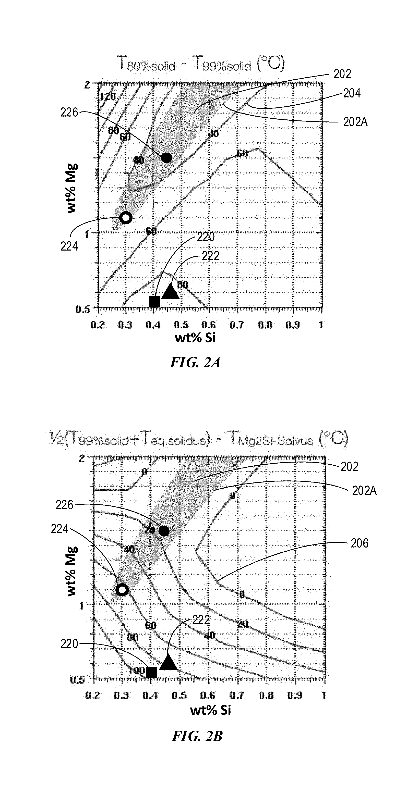
[0112] FIG. 3A depicts an example composition space with Mg from 0.5 wt % to 3 wt % and Si from 0.2 wt % to 1.0 wt % for compositions having various Scheil temperatures and solvus temperatures in accordance with embodiments of the disclosure. As shown, curves 306A-E represent the constant Scheil temperatures, 450.degree. C., 500.degree. C., 550.degree. C., 570.degree. C., and 590.degree. C., respectively. Curves 408A-F represent constant solvus temperatures 590.degree. C., 570.degree. C., 550.degree. C., 530.degree. C., 510.degree. C., and 490.degree. C., respectively. In region 302, the solvus temperature of Mg.sub.2Si is lower than the Scheil temperature such that the alloy can be heat treated to obtain a cosmetically attractive anodized finish. The solvus temperature obtained from FIG. 3A is also listed in Table 1.
[0113] FIG. 3B depicts an example composition space with Mg from 0.5 wt % to 3 wt % and Si from 0.2 wt % to 1.0 wt % for compositions having various solidification temperature ranges in accordance with embodiments of the disclosure. As shown in FIG. 3B, curves 314A-E represent solidification temperature ranges 180.degree. C., 140.degree. C., 100.degree. C., 80.degree. C., and 60.degree. C., respectively. Region 310 is within a solidification temperature range of 60.degree. C., and region 316 is within a solidification temperature range of 80.degree. C. As disclosed herein, the solidification temperature range is the difference between the solidus temperature and the Scheil temperature. There is an overlapping region between region 310 and region 316. The alloys can have greater processablity or additive manufacturability in region 310 than in the non-overlapping region within region 316, but outside region 310.
[0114] As shown in FIG. 3B, Example Alloys 5 (Al-1.2Mg-0.3Si) and 6 (Al-1.5Mg-0.4Si) are within the "great cosmetic appeal" region in which the alloys can have greater additive manufacturability and cosmetic appeal than other regions. Example Alloy 7 (Al-1.9Mg-0.55Si) can have greater additive manufacturability than other regions and have the cosmetic appeal not as good as Example Alloys 5-6, but still has "good cosmetic appeal". The "great cosmetic appeal" region also covers the composition space of both alloys 6063 and 6061.
[0115] As disclosed herein, the alloys can have a cosmetically attractive anodized finish in region 302, and can have better additive manufacturability in region 310. In an overlapping region 312 between region 310 and region 302, the alloys can have better additive manufacturability and better cosmetically attractive anodized finish than other regions.
[0116] Within the non-overlapping region between region 312 and region 302, the alloys can have better additive manufacturability than any other regions. The alloys can also have less cosmetically attractive anodized finish in the non-overlapping region than the region 312, because the solidification temperature range for the non-overlapping region is 80.degree. C. in the non-overlapping region, higher than a solidification temperature range of 60.degree. C. of region 312. Lower solidification temperature range is more desirable for better additive manufacturability.
[0117] Region 316 bounded by dashed lines 314D is within solidification temperature range 80.degree. C. Within region 316 but outside region 310 and outside region 302, the alloys can have less additive manufacturability than region 310 and less cosmetically attractive anodized finish than region 302.
[0118] FIG. 3C depicts an example composition space with Mg from 0.5 wt % to 8 wt % and Si from 0.2 wt % to 3 wt % for compositions having various solidification temperature ranges in accordance with embodiments of the disclosure. As shown, curves 314A-D represent solidification temperature ranges 180.degree. C., 140.degree. C., 100.degree. C. and 60.degree. C., respectively. Region 310 is bounded by curve 314D, i.e. solidification temperature range 60.degree. C. Region 310 includes Mg from about 1.4 wt % to about 7 wt %, Si from about 0.4 wt % to 3 wt %. If the solidification temperature range becomes 80.degree. C., the Mg and Si ranges may vary. For example, the Si may be as low as 0.2 wt % and Mg may be as low as 1.0 wt %. The weight ratio of Mg to Si can vary from about 2 to about 3 based on curves 314D and 314E for solidification temperature ranges of 80.degree. C. and 60.degree. C. Example Alloy 8 (Al-3.5Mg-1.2Si) can have greater additive manufacturability than other regions and have a cosmetic appeal less than Example Alloys 5-6, but still has "good cosmetic appeal."
[0119] In some aspects, the total of one or more of elements Cu, Cr and Mn may not exceed a threshold total quantity. In some embodiments, the total of one or more of elements Cu, Cr, and Mn is equal to or less than 0.1 wt %. In some embodiments, the total of one or more of elements Cu, Cr, and Mn is equal to or less than 0.08 wt %. In some embodiments, the total of one or more of elements Cu, Cr, and Mn is equal to or less than 0.06 wt %. In some embodiments, the total of one or more of elements Cu, Cr, and Mn is equal to or less than 0.04 wt %. In some embodiments, the total of one or more of elements Cu, Cr, and Mn is equal to or less than 0.02 wt %.
[0120] In some aspects, the Al alloys can include a small amount of incidental impurities. The impurity elements can be can be present, for example, as a byproduct of processing and manufacturing. The impurities can be less than or equal to about 2 wt %, alternatively less than or equal about 1 wt %, alternatively less than or equal about 0.5 wt %, alternatively less than or equal about 0.1 wt %.
[0121] IV. Additive Manufacturing
[0122] Additive Manufacturing (AM) technologies provide methods for building three dimensional (3D) objects by adding layer-upon-layer of material. The material includes metal or plastic among others. One of the common to AM technologies is the use of a computer, 3D modeling software such as Computer Aided Design (CAD), machine equipment and layering material. Once a CAD sketch is produced, the AM equipment reads in data from the CAD file and lays downs or adds successive layers of liquid, powder, sheet material or other, in a layer-upon-layer fashion to fabricate a 3D object.
[0123] The AM encompasses many technologies including subsets like 3D Printing, Rapid Prototyping, Direct Digital Manufacturing (DDM), layered manufacturing and additive fabrication.
[0124] The early use of AM in the form of Rapid Prototyping focused on preproduction visualization models. More recently, the AM is being used to fabricate end-use products.
[0125] In some embodiments, the alloys can be atomized to form a powder. Atomization is accomplished by forcing a molten metal stream through an orifice at moderate pressures. The atomized powder can be locally heated by using laser or electron beam.
[0126] The present alloys can be used for additive manufacturing (e.g., 3D printing), which constructs a part from a powder layer by layer. During additive manufacturing, the powder can be deposited and locally melted. The deposition and fusing of the powder can be repeated as needed to construct the part, layer by layer.
[0127] For example, a first layer of powder formed of the Al alloy can spread out over a mold base. A laser beam can heat up the power above the melting point. The powder heated by the laser is fused together. The fused powder is cooled down. A second layer of fresh powder can spread over the first layer of alloy. The second layer of powder is heated up by the laser beam above the melting point such that the powder is fused together. The second fused layer of powder is cooled down for form a layer of alloy over the first layer of alloy. This process continues with another layer of powder. Each of the additional layers of powder is built up over the previous alloy layer, not over the mold base.
[0128] V. Non-Iron Mold (i.e. Non-Die) Casting
[0129] The alloys can produce a cosmetically appealing anodized finish, and/or to have a yield strength of at least 200 MPa. These alloys may be used to fabricate electronic housings by non-metal mold casting, such as sand casting or investment casting. The sand casting uses sand as the mold material. Over 70% of all metal castings are produced via sand casting process.
[0130] Investment casting uses waxes, refractory materials (e.g. ceramic materials and glasses) for making molds. Investment casting is valued for its ability to produce components with accuracy, repeatability, versatility and integrity in a variety of metals and high-performance alloys.
[0131] During casting, an alloy melt is poured into a mold cavity that is an exact duplicate of the desired part. The investment casting can produce complicated shapes that would be difficult with other casting methods. It can also produce products with exceptional surface qualities and low tolerances with minimal surface finishing or machining required.
[0132] The present alloys are not suitable for iron-based mold. This is because that the present aluminum alloys contain very small amount of Fe and are more likely to stick to the iron-based metal mold by forming alloys including Fe.
[0133] In some embodiments, a melt for an alloy can be prepared by heating the alloy including the composition, for example, as depicted in Table 1. After the melt is cooled to room temperature, the alloys may go through various heat treatments, such homogenization, extruding, forging, aging, and/or other forming or solution heat treatment techniques. Homogeneous treatment or solution treatment dissolves second phase particles or precipitates.
[0134] The alloy can fill a mold more completely during casting with reduced risk of hot tearing. In various embodiments, the alloys can have a small solidification temperature range, which can result in improved additive manufacturability of the alloys. As an example, the commercial alloy 6063 has a large solidification temperature range and a small eutectic fraction, which is not suitable for casting.
[0135] FIG. 7A depicts an example mold cavity in accordance with embodiments of the disclosure. The mold cavity 702 has an H-shape with two vertical arms and a thin horizontal portion to connect the two arms. As shown by the arrow, molten aluminum 704 can be injected into a thin middle portion from a filling channel 716 and can be forced to flow into the mold cavity 702.
[0136] FIG. 7B depicts an example of partial mold filling following FIG. 7A in accordance with embodiments of the disclosure. Molten aluminum 704 completely fills the horizontal middle portion and partially fills the vertical arms of the mold cavity 702.
[0137] FIG. 7C depicts an example of complete mold filling following FIG. 7B in accordance with embodiments of the disclosure. As depicted, molten aluminum 708 completely fills the vertical arms and the horizontal middle portion of mold cavity 702.
[0138] FIG. 7D depicts an example of partial solidification following FIG. 7C in accordance with embodiments of the disclosure. The molten aluminum in the two vertical arms of the cavity 702 has solidified (portion 710), while the molten aluminum still remains partially unsolidified in the horizontal middle portion (portion 712).
[0139] FIG. 7E depicts an example of complete solidification following FIG. 7D in accordance with embodiments of the disclosure. As depicted, there is a remaining small amount of liquid in the filling channel 716. The alloy in the thinner horizontal portion of the mold cavity experiences a tensile stress as arrows pointed. The tensile stress is induced by the alloy contraction in the two vertical arms during a phase transition from liquid to solid.
[0140] FIG. 7F depicts an example of the alloy in the mold cavity without any hot tearing following FIG. 7E in accordance with embodiments of the disclosure. The alloy has a large eutectic fraction 102 as shown in FIG. 1, which can result in less contraction and thus a lower tensile stress.
[0141] FIG. 7G depicts an example of the alloy in the mold cavity with hot tearing in the middle of the thin portion following FIG. 7E in accordance with embodiments of the disclosure. The commercial alloy (e.g. 6063-T6) has a small eutectic fraction 104 as shown in FIG. 1, which may result in a larger contraction and thus a higher tensile stress.
[0142] Castability of the alloys may be quantitatively evaluated. For example, by using the H-shape mold cavity, shown in FIG. 7A, the middle portion may vary in thickness.
[0143] Quantitative evaluations of castability are described below. FIGS. 8A-8B depict an example mold cavity middle portion 802 with varying thicknesses: thinner mold cavity (FIG. 8A) and thicker mold cavity (FIG. 8B). An alloy may be characterized by filling the mold cavity. In some embodiments, when the alloy can fill the thinner mold cavity, the alloy may have a better fluidity or castability than the alloy can only fill a thicker mold cavity. In some embodiments, the alloy may fill the mold cavity partially, and the filled distance can be measured to quantify the fluidity of the alloy.
[0144] In various embodiments, the alloy may be casted at a casting temperature ranging from 50.degree. C. to 100.degree. C. higher than the liquidus temperature of the alloy. In some embodiments, the casting temperature is up to 100.degree. C. higher than the liquidus temperature of the alloy. In some embodiments, the casting temperature is up to 90.degree. C. higher than the liquidus temperature of the alloy. In some embodiments, the casting temperature is up to 80.degree. C. higher than the liquidus temperature of the alloy. In some embodiments, the casting temperature is up to 70.degree. C. higher than the liquidus temperature of the alloy. In some embodiments, the casting temperature is up to 60.degree. C. higher than the liquidus temperature of the alloy. In some embodiments, the casting temperature is up to 50.degree. C. higher than the liquidus temperature of the alloy.
[0145] In various embodiments, the liquidus temperature of the alloy is about 650.degree. C. Accordingly, the casting temperature ranges from 700.degree. C. to 750.degree. C. In some embodiments, the casting temperature is up to 750.degree. C. In some embodiments, the casting temperature is up to 740.degree. C. In some embodiments, the casting temperature is up to 730.degree. C. In some embodiments, the casting temperature is up to 720.degree. C. In some embodiments, the casting temperature is up to 710.degree. C. In some embodiments, the casting temperature is up to 700.degree. C. In some embodiments, the casting temperature may be greater than 700.degree. C. In some embodiments, the casting temperature may be greater than 710.degree. C. In some embodiments, the casting temperature may be greater than 720.degree. C. In some embodiments, the casting temperature may be greater than 730.degree. C. In some embodiments, the casting temperature may be greater than 740.degree. C.
[0146] In various embodiments, a shot sleeve used to deliver an amount of the melted alloy may be maintained at a temperature ranging from about 200.degree. C. to about 500.degree. C. In some embodiments, the shot sleeve may be maintained at a temperature of at least 200.degree. C. In some embodiments, the shot sleeve may be maintained at a temperature of at least 250.degree. C. In some embodiments, the shot sleeve may be maintained at a temperature of at least 300.degree. C. In some embodiments, the shot sleeve may be maintained at a temperature of at least 350.degree. C. In some embodiments, the shot sleeve may be maintained at a temperature of at least 400.degree. C. In some embodiments, the shot sleeve may be maintained at a temperature of at least 450.degree. C. In some embodiments, the shot sleeve may be maintained at a temperature of less than 500.degree. C. In some embodiments, the shot sleeve may be maintained at a temperature of less than 450.degree. C. In some embodiments, the shot sleeve may be maintained at a temperature of less than 400.degree. C. In some embodiments, the shot sleeve may be maintained at a temperature of less than 350.degree. C. In some embodiments, the shot sleeve may be maintained at a temperature of less than 300.degree. C. In some embodiments, the shot sleeve may be maintained at a temperature of less than 250.degree. C.
[0147] In various embodiments, the alloy may be casted into a non-metal mold maintained at a temperature ranging from about 200.degree. C. to about 500.degree. C. In some embodiments, the non-metal mold may be maintained at a temperature of at least 200.degree. C. In some embodiments, the non-metal mold may be maintained at a temperature of at least 250.degree. C. In some embodiments, the non-metal mold may be maintained at a temperature of at least 300.degree. C. In some embodiments, the non-metal mold may be maintained at a temperature of at least 350.degree. C. In some embodiments, the non-metal mold may be maintained at a temperature of at least 400.degree. C. In some embodiments, the non-metal mold may be maintained at a temperature of at least 450.degree. C. In some embodiments, the non-metal mold may be maintained at a temperature of less than 500.degree. C. In some embodiments, the non-metal mold may be maintained at a temperature of less than 450.degree. C. In some embodiments, the non-metal mold may be maintained at a temperature of less than 400.degree. C. In some embodiments, the non-metal mold may be maintained at a temperature of less than 350.degree. C. In some embodiments, the non-metal mold may be maintained at a temperature of less than 300.degree. C. In some embodiments, the non-metal mold may be maintained at a temperature of less than 250.degree. C.
[0148] In various embodiments, the solidification temperature ranges is smaller than 60.degree. C. In some embodiments, the solidification temperature ranges is smaller than 55.degree. C. In some embodiments, the solidification temperature ranges is smaller than 50.degree. C. In some embodiments, the solidification temperature ranges is smaller than 45.degree. C. In some embodiments, the solidification temperature ranges is smaller than 40.degree. C. In some embodiments, the solidification temperature ranges is smaller than 35.degree. C. In some embodiments, the solidification temperature ranges is smaller than 30.degree. C. In some embodiments, the solidification temperature ranges is smaller than 25.degree. C. In some embodiments, the solidification temperature ranges is smaller than 20.degree. C. In some embodiments, the solidification temperature ranges is smaller than 15.degree. C. In some embodiments, the solidification temperature ranges is smaller than 10.degree. C. In some embodiments, the solidification temperature ranges is smaller than 5.degree. C. It will be appreciated by those skilled in the art that the composition space may vary with the solidification temperature range.
[0149] Having described several embodiments, it will be recognized by those skilled in the art that various modifications, alternative constructions, and equivalents may be used without departing from the spirit of the disclosure. Additionally, a number of well-known processes and elements have not been described in order to avoid unnecessarily obscuring the embodiments disclosed herein. Accordingly, the above description should not be taken as limiting the scope of the document.
[0150] Those skilled in the art will appreciate that the presently disclosed embodiments teach by way of example and not by limitation. Therefore, the matter contained in the above description or shown in the accompanying drawings should be interpreted as illustrative and not in a limiting sense. The following claims are intended to cover all generic and specific features described herein, as well as all statements of the scope of the present method and system, which, as a matter of language, might be said to fall there between.
* * * * *
D00000
D00001
D00002
D00003
D00004
D00005
D00006
D00007
D00008
D00009
XML
uspto.report is an independent third-party trademark research tool that is not affiliated, endorsed, or sponsored by the United States Patent and Trademark Office (USPTO) or any other governmental organization. The information provided by uspto.report is based on publicly available data at the time of writing and is intended for informational purposes only.
While we strive to provide accurate and up-to-date information, we do not guarantee the accuracy, completeness, reliability, or suitability of the information displayed on this site. The use of this site is at your own risk. Any reliance you place on such information is therefore strictly at your own risk.
All official trademark data, including owner information, should be verified by visiting the official USPTO website at www.uspto.gov. This site is not intended to replace professional legal advice and should not be used as a substitute for consulting with a legal professional who is knowledgeable about trademark law.