Vehicle Body Structure and Rail Train with Vehicle Body
ZHANG; Conghui ; et al.
U.S. patent application number 16/194607 was filed with the patent office on 2019-06-06 for vehicle body structure and rail train with vehicle body. The applicant listed for this patent is CRRC QINGDAO SIFANG CO., LTD.. Invention is credited to Jian LI, Peng LI, Shudian LI, Shengguang WANG, Conghui ZHANG.
| Application Number | 20190168783 16/194607 |
| Document ID | / |
| Family ID | 63778180 |
| Filed Date | 2019-06-06 |


| United States Patent Application | 20190168783 |
| Kind Code | A1 |
| ZHANG; Conghui ; et al. | June 6, 2019 |
Vehicle Body Structure and Rail Train with Vehicle Body
Abstract
A vehicle body structure and a rail train with the vehicle body. The vehicle body structure includes a vehicle body, an air duct and a maintenance portion, wherein the air duct is provided at the bottom of the vehicle body, the air duct has a maintenance port, the maintenance portion is connected to the air duct and located at the maintenance port, and the maintenance portion has an opening position for opening the maintenance port and a closing position for closing the maintenance port. By operating a maintenance portion on an air duct at the bottom of a vehicle body, a maintenance port of the air duct is at an opened or closing position, in order to detect or repair the interior of the air duct, thus prolonging the life of the air duct of the vehicle body structure and improving the reliability.
| Inventors: | ZHANG; Conghui; (Qingdao, CN) ; LI; Jian; (Qingdao, CN) ; LI; Shudian; (Qingdao, CN) ; WANG; Shengguang; (Qingdao, CN) ; LI; Peng; (Qingdao, CN) | ||||||||||
| Applicant: |
|
||||||||||
|---|---|---|---|---|---|---|---|---|---|---|---|
| Family ID: | 63778180 | ||||||||||
| Appl. No.: | 16/194607 | ||||||||||
| Filed: | November 19, 2018 |
| Current U.S. Class: | 1/1 |
| Current CPC Class: | B61D 27/00 20130101; B61F 1/08 20130101; B61D 27/0009 20130101 |
| International Class: | B61D 27/00 20060101 B61D027/00 |
Foreign Application Data
| Date | Code | Application Number |
|---|---|---|
| May 8, 2018 | CN | 201810433981.7 |
Claims
1. A vehicle body structure, comprising: a vehicle body; an air duct, the air duct being provided at a bottom of the vehicle body, and the air duct having a maintenance port; and a maintenance portion, the maintenance portion being connected with the air duct and located at the maintenance port, and the maintenance portion having an opening position for opening the maintenance port and a closing position for closing the maintenance port.
2. The vehicle body structure as claimed in claim 1, wherein the air duct comprises: a main air duct, the main air duct being provided along a length direction of the vehicle body, and an air supply opening being provided in a middle of the main air duct; and a branch air duct, the branch air duct being provided along a width direction of the vehicle body, a first end of the branch air duct being communicated with the main air duct, and a second end of the branch air duct having an air outlet for communicating with an interior of the vehicle body.
3. The vehicle body structure as claimed in claim 2, wherein the main air duct and/or the branch air duct are/is provided with the maintenance portion.
4. The vehicle body structure as claimed in claim 2, further comprising: a guide portion, the guide portion being provided in the air duct to guide or distribute airflow in the air duct.
5. The vehicle body structure as claimed in claim 4, wherein the guide portion comprises: a first guide plate, the first guide plate being provided at the air supply opening and located in the air duct, and/or the first guide plate being provided at a joint between the main air duct and the branch air duct and located in the air duct, wherein, the first guide plate being a herringbone guide plate.
6. The vehicle body structure as claimed in claim 4, wherein a second end, provided with the air outlet, of the branch air duct is an arc-shaped structure, and the guide portion comprises: a second guide plate, the second guide plate being provided in the second end of the branch air duct to divide the second end of the branch air duct into at least two independent air outlet ducts.
7. The vehicle body structure as claimed in claim 2, wherein the air supply opening and/or the air outlet are/is provided with a flange, a seal ring being provided in the flange.
8. The vehicle body structure as claimed in claim 2, wherein there are a plurality of branch air ducts, the plurality of branch air ducts being provided at intervals along the length direction of the vehicle body.
9. The vehicle body structure as claimed in claim 8, wherein the plurality of branch air ducts are symmetrically provided on two sides of the main air duct.
10. The vehicle body structure as claimed in claim 2, wherein the air duct comprises: a return air duct, a first end of the return air duct being communicated with the main air duct, and a second end of the return air duct being communicated with the interior of the vehicle body.
11. The vehicle body structure as claimed in claim 1, wherein the maintenance portion is a maintenance cover plate, the maintenance cover plate being detachably provided at the maintenance port.
12. A rail train, comprising a vehicle body structure, wherein the vehicle body structure is the vehicle body structure as claimed in claim 1.
13. A rail train, comprising a vehicle body structure, wherein the vehicle body structure is the vehicle body structure as claimed in claim 2.
14. A rail train, comprising a vehicle body structure, wherein the vehicle body structure is the vehicle body structure as claimed in claim 3.
15. A rail train, comprising a vehicle body structure, wherein the vehicle body structure is the vehicle body structure as claimed in claim 4.
16. A rail train, comprising a vehicle body structure, wherein the vehicle body structure is the vehicle body structure as claimed in claim 5.
17. A rail train, comprising a vehicle body structure, wherein the vehicle body structure is the vehicle body structure as claimed in claim 6.
18. A rail train, comprising a vehicle body structure, wherein the vehicle body structure is the vehicle body structure as claimed in claim 7.
19. A rail train, comprising a vehicle body structure, wherein the vehicle body structure is the vehicle body structure as claimed in claim 8.
20. A rail train, comprising a vehicle body structure, wherein the vehicle body structure is the vehicle body structure as claimed in claim 9.
Description
CROSS REFERENCE TO RELATED APPLICATION
[0001] This application is related to and claims the benefit of Chinese Patent Application Number 201810433981.7 filed on May 8, 2018, the contents of which are incorporated herein by reference in their entirety.
TECHNICAL FIELD
[0002] Embodiments of the present disclosure relate to a field of an air-conditioning ventilation design of vehicle, and in particular to a vehicle body structure and a rail train with the vehicle body.
BACKGROUND
[0003] A train air-conditioning unit and an air supply device are generally disposed at the top of a carriage, and an air supply duct is connected with the air-conditioning unit. This vehicle air duct system adopts an air supply form having a top static pressure chamber, and is not provided with an independent return air duct. This air-conditioning system does not facilitate the requirement of a high-speed train for low center of gravity, and the vehicle air duct system is bad in uniformity of micro air speed and temperature distribution. Moreover, airflow at an air supply opening of the existing vehicle air duct system is easily eddied, thereby not facilitating the airflow guide effect of an air duct on airflow. Furthermore, the existing vehicle air duct system is non-detachable, thus causing the problem of difficulty in detection or repair of the air duct.
SUMMARY
[0004] A main objective of the present disclosure is to provide a vehicle body structure and a rail train with the vehicle body, intended to solve the problem in the conventional art of difficulty in detection or repair of the air duct.
[0005] To achieve the above objective, according to an aspect of the present disclosure, a vehicle body structure is provided. The vehicle body structure includes a vehicle body; an air duct, the air duct being provided at a bottom of the vehicle body, and the air duct having a maintenance port; and a maintenance portion, the maintenance portion being connected with the air duct and located at the maintenance port, and the maintenance portion having an opening position for opening the maintenance port and a closing position for closing the maintenance port.
[0006] In some embodiments, wherein the air duct includes: a main air duct, the main air duct being provided along a length direction of the vehicle body, and an air supply opening being provided in a middle of the main air duct; and a branch air duct, the branch air duct being provided along a width direction of the vehicle body, a first end of the branch air duct being communicated with the main air duct, and a second end of the branch air duct having an air outlet for communicating with an interior of the vehicle body.
[0007] In some embodiments, wherein the main air duct and/or the branch air duct are/is provided with the maintenance portion.
[0008] In some embodiments, further including: a guide portion, the guide portion being provided in the air duct to guide or distribute airflow in the air duct.
[0009] In some embodiments, wherein the guide portion includes: a first guide plate, the first guide plate being provided at the air supply opening and located in the air duct, and/or the first guide plate being provided at a joint between the main air duct and the branch air duct and located in the air duct, wherein, the first guide plate being a herringbone guide plate.
[0010] In some embodiments, wherein a second end, provided with the air outlet, of the branch air duct is an arc-shaped structure, and the guide portion includes: a second guide plate, the second guide plate being provided in the second end of the branch air duct to divide the second end of the branch air duct into at least two independent air outlet ducts.
[0011] In some embodiments, wherein the air supply opening and/or the air outlet are/is provided with a flange, a seal ring being provided in the flange.
[0012] In some embodiments, wherein there are a plurality of branch air ducts, the plurality of branch air ducts being provided at intervals along the length direction of the vehicle body.
[0013] In some embodiments, wherein the plurality of branch air ducts are symmetrically provided on two sides of the main air duct.
[0014] In some embodiments, wherein the air duct includes: a return air duct, a first end of the return air duct being communicated with the main air duct, and a second end of the return air duct being communicated with the interior of the vehicle body.
[0015] In some embodiments, wherein the maintenance portion is a maintenance cover plate, the maintenance cover plate being detachably provided at the maintenance port.
[0016] According to another aspect of the present disclosure, a rail train is provided. The rail train includes a vehicle body structure, the vehicle body structure being the above vehicle body structure.
[0017] According to the technical solution of the present disclosure, a maintenance portion is provided on an air duct at the bottom of a vehicle body. By operating the maintenance portion, a maintenance port of the air duct is at an opened or closing position, in order to detect or repair the interior of the air duct, thus prolonging the life of the air duct of the vehicle body structure and improving the reliability.
BRIEF DESCRIPTION OF THE DRAWINGS
[0018] The accompanying drawings, which constitute a part of this application, are used to provide a further understanding of the present disclosure, and the exemplary embodiments of the present disclosure and the description thereof are used to explain the present disclosure, but do not constitute improper limitations to the present disclosure. In the drawings:
[0019] FIG. 1 illustrates a structure diagram of a vehicle body structure according to embodiment 1 of the present disclosure;
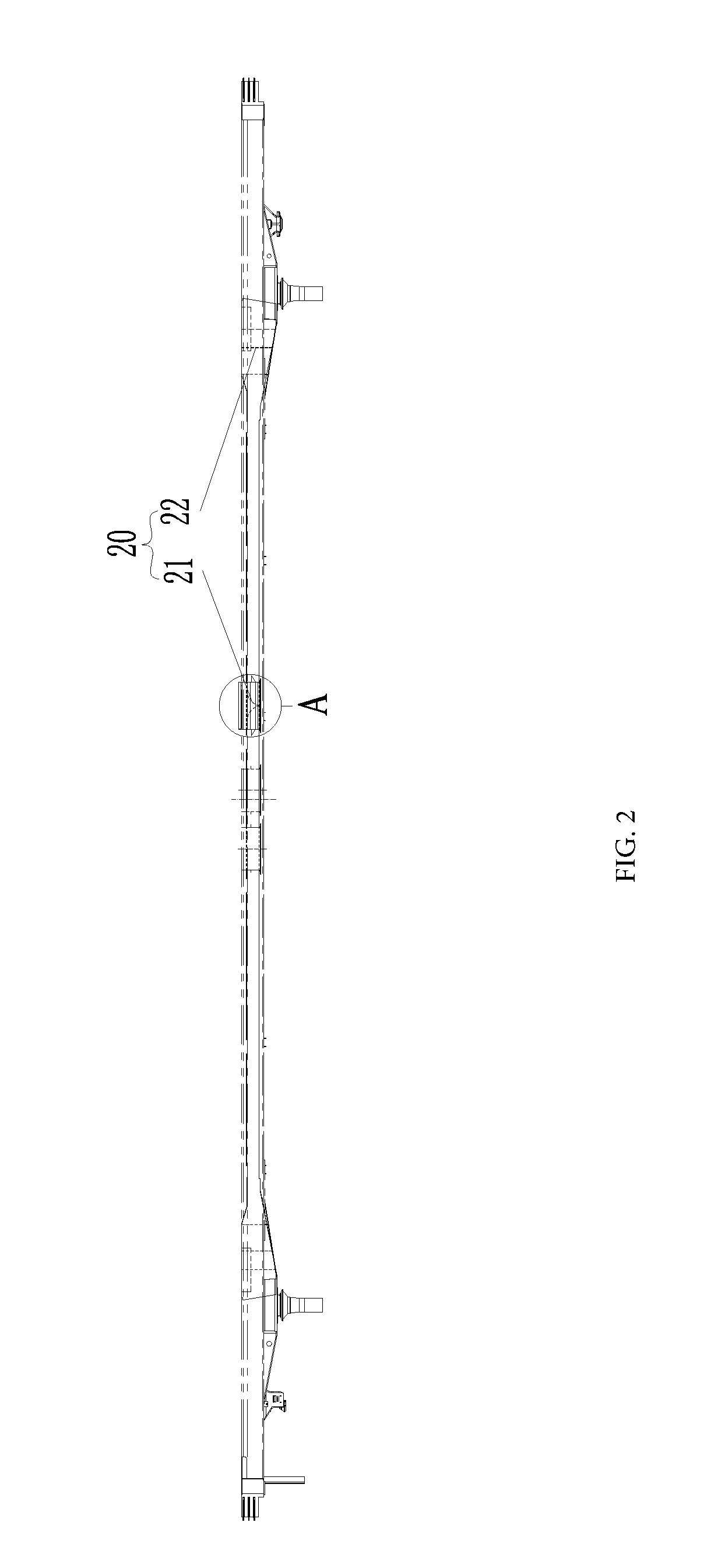
[0020] FIG. 2 illustrates a longitudinal sectional structure diagram of a vehicle body structure according to embodiment 2 of the present disclosure;
[0021] FIG. 3 illustrates an enlarged structure diagram of part A in FIG. 2;
[0022] FIG. 4 illustrates a horizontal sectional structure diagram of a vehicle body structure according to embodiment 3 of the present disclosure; and
[0023] FIG. 5 illustrates a horizontal sectional structure diagram of a vehicle body structure according to embodiment 4 of the present disclosure.
[0024] THE DRAWINGS INCLUDE THE FOLLOWING REFERENCE SIGNS
[0025] 10: air duct; 11: main air duct; 111: air supply opening; 12: branch air duct; 121: air outlet; 13: maintenance portion; 14: return air duct;
[0026] 20: guide portion; 21: first guide plate; 22: second guide plate;
[0027] 30: flange.
DETAILED DESCRIPTION OF THE EMBODIMENTS
[0028] It is to be noted that in the case of no conflict, the features in the embodiments and the embodiments in the present application may be combined with each other. The present disclosure is described below with reference to the drawings and in conjunction with the embodiments in detail.
[0029] It is to be noted that terms used herein only aim to describe specific implementation manners, and are not intended to limit exemplar implementations of this application. Unless otherwise directed by the context, singular forms of terms used herein are intended to include plural forms. Besides, it will be also appreciated that when terms "contain" and/or "include" are used in the description, it is indicated that features, steps, operations, devices, assemblies and/or a combination thereof exist.
[0030] As shown in FIG. 1 to FIG. 5, according to an embodiment of the present disclosure, a vehicle body structure is provided.
[0031] Specifically, as shown in FIG. 1, the vehicle body structure includes: a vehicle body, an air duct 10 and a maintenance portion 13. The air duct 10 is disposed at the bottom of the vehicle body. The air duct 10 has a maintenance port. The maintenance portion 13 is connected with the air duct 10 and located at the maintenance port. The maintenance portion 13 has an opening position for opening the maintenance port and a closing position for closing the maintenance port.
[0032] In the present embodiment, a maintenance portion is provided on an air duct at the bottom of a vehicle body. By operating the maintenance portion, a maintenance port of the air duct is at an opened or closing position, in order to detect or repair the interior of the air duct, thus prolonging the life of the air duct of the vehicle body structure and improving the reliability.
[0033] In the present embodiment, the air duct 10 includes a main air duct 11 and a branch air duct 12. The main air duct 11 is provided along a length direction of the vehicle body, and the middle of the main air duct 11 is provided with an air supply opening 111. The branch air duct 12 is provided along a width direction of the vehicle body, a first end of the branch air duct 12 is communicated with the main air duct 11, and a second end of the branch air duct 12 has an air outlet 121 for communicating with the interior of the vehicle body. By connecting the branch air duct to the main air duct, air generated by an air conditioner can be delivered into the vehicle body through the branch air duct in all directions, thereby improving the use experience of a user.
[0034] As shown in FIG. 1, the main air duct 11 or the branch air duct 12 is provided with the maintenance portion 13. Of course, both the main air duct 11 and the branch air duct 12 may be provided with the maintenance portions 13. Such arrangement enables the main air duct 11 and the branch air duct 12 to be detected or repaired by the maintenance portions, thus prolonging the life of the air duct of the vehicle body structure and improving the reliability.
[0035] As shown in FIG. 2, the vehicle body structure further includes a guide portion 20, the guide portion 20 being disposed in the air duct 10 to guide or distribute airflow in the air duct 10. Such arrangement avoids an eddy at the air supply opening, thus improving the flowing stability of airflow in the air duct.
[0036] As shown in FIG. 3, the guide portion 20 includes a first guide plate 21. The first guide plate 21 is disposed at the air supply opening 111 and located in the air duct 10, and/or the first guide plate 21 is disposed at a joint between the main air duct 11 and the branch air duct 12 and located in the air duct 10, wherein the first guide plate 21 is a herringbone guide plate. The herringbone guide plate distributes airflow at the air supply opening and avoids an eddy, thus improving the flowing stability of airflow in the air duct.
[0037] As shown in FIG. 2, FIG. 4 and FIG. 5, the second end, provided with the air outlet 121, of the branch air duct 12 is an arc-shaped structure, and the guide portion 20 includes a second guide plate 22, the second guide plate 22 being disposed in the second end of the branch air duct 12 to divide the second end of the branch air duct 12 into at least two independent air outlet ducts. The second guide plate here may be an arc-shaped guide plate, and there is at least one arc-shaped guide plate. Such arrangement enables the second guide plate namely the arc-shaped guide plate to directionally guide airflow and avoids an eddy.
[0038] As shown in FIG. 1, the air supply opening 111 or the air outlet 121 is provided with a flange 30. Of course, they may be both provided with a flange. A seal ring is provided in the flange 30. Such arrangement achieves firm mounting of a pipeline communicated with the air supply opening and the air outlet, and good sealing performance.
[0039] In the present embodiment, there are multiple branch air ducts 12, the multiple branch air ducts 12 being provided at intervals along the length direction of the vehicle body. By connecting the multiple branch air ducts to the main air duct, air generated by an air conditioner can be delivered into the vehicle body through the branch air duct in all directions, thereby improving the use experience of a user.
[0040] In the present embodiment, the multiple branch air ducts 12 are symmetrically disposed on two sides of the main air duct 11. Such arrangement facilitates mounting of the branch air duct 12, and improves the stability of airflow in the air duct.
[0041] As shown in FIG. 1, the air duct 10 includes a return air duct 14. A first end of the return air duct 14 is communicated with the main air duct 11, and a second end of the return air duct 14 is communicated with the interior of the vehicle body. At least one end of the return air duct is provided with a flange, in order to mount the return air duct. Such arrangement enables interior airflow in the vehicle body to return into the air conditioner through the return air duct.
[0042] In the present embodiment, the maintenance portion 13 is a maintenance cover plate. The maintenance cover plate is detachably disposed at the maintenance port. The maintenance cover plate is connected to a pipeline wall on the periphery of the maintenance port in a fastening connection manner, and a rubber pad is disposed in the maintenance cover plate to improve the sealing performance of connection between the maintenance cover plate and the maintenance port.
[0043] The vehicle body structure of the above embodiments may also be used for the technical field of rail traffic. That is to say, according to another aspect of the present disclosure, a rail train is provided. The rail train includes a vehicle body structure, and the vehicle body structure is the vehicle body structure in the above embodiments.
[0044] In the present embodiments, the vehicle body structure provides the air duct at the bottom of the vehicle body, thereby saving the interior space of the vehicle, and improving the ride comfort of a passenger. It is applied to a small-section vehicle model. The air duct is compact in structure and convenient to mount, facilitates effective utilization of a vehicle space, and facilitates maintenance of an air duct system.
[0045] In the above embodiment, descriptions of each embodiment are emphasized respectively, and parts which are not elaborated in detail in a certain embodiment may refer to relevant descriptions of other embodiments.
[0046] The above is only the preferred embodiments of the present disclosure, not intended to limit the present disclosure. As will occur to those skilled in the art, the present disclosure is susceptible to various modifications and changes. Any modifications, equivalent replacements, improvements and the like made within the spirit and principle of the present disclosure shall fall within the scope of protection of the present disclosure.
* * * * *
D00000
D00001
D00002
D00003
XML
uspto.report is an independent third-party trademark research tool that is not affiliated, endorsed, or sponsored by the United States Patent and Trademark Office (USPTO) or any other governmental organization. The information provided by uspto.report is based on publicly available data at the time of writing and is intended for informational purposes only.
While we strive to provide accurate and up-to-date information, we do not guarantee the accuracy, completeness, reliability, or suitability of the information displayed on this site. The use of this site is at your own risk. Any reliance you place on such information is therefore strictly at your own risk.
All official trademark data, including owner information, should be verified by visiting the official USPTO website at www.uspto.gov. This site is not intended to replace professional legal advice and should not be used as a substitute for consulting with a legal professional who is knowledgeable about trademark law.