Grinding Disc Device for a Grinding Apparatus
Brandstetter; Josef
U.S. patent application number 16/132994 was filed with the patent office on 2019-06-06 for grinding disc device for a grinding apparatus. This patent application is currently assigned to JOBRA Metall GmbH. The applicant listed for this patent is JOBRA Metall GmbH. Invention is credited to Josef Brandstetter.
| Application Number | 20190168361 16/132994 |
| Document ID | / |
| Family ID | 60889739 |
| Filed Date | 2019-06-06 |


| United States Patent Application | 20190168361 |
| Kind Code | A1 |
| Brandstetter; Josef | June 6, 2019 |
Grinding Disc Device for a Grinding Apparatus
Abstract
A grinding disc device for a grinding apparatus is described, having at least one grinding layer and a carrier disc fixedly connected to the grinding layer. The grinding layer has at least one connection surface (F.sub.V) connected to the carrier disc and forms an abrasive grinding surface (F.sub.S) lying opposite the connection surface (F.sub.V) and facing away from the carrier disc. The carrier disc made of a plastic material is produced by injection molding and is connected immediately and directly to the connection surface (F.sub.V) of the grinding layer, wherein the plastic material of the carrier disc is sprayed by injection molding immediately and directly onto the connection surface (F.sub.V) of the grinding layer, such that the carrier disc and the grinding layer are connected to one another in a material-locking manner.
| Inventors: | Brandstetter; Josef; (Rottenberg a.d. Laaber, DE) | ||||||||||
| Applicant: |
|
||||||||||
|---|---|---|---|---|---|---|---|---|---|---|---|
| Assignee: | JOBRA Metall GmbH Rottenberg a.d. Laaber DE |
||||||||||
| Family ID: | 60889739 | ||||||||||
| Appl. No.: | 16/132994 | ||||||||||
| Filed: | September 17, 2018 |
| Current U.S. Class: | 1/1 |
| Current CPC Class: | B24D 13/20 20130101; B24D 13/14 20130101; B24D 18/00 20130101; B24D 13/18 20130101; B24D 9/08 20130101; B24D 7/16 20130101 |
| International Class: | B24D 9/08 20060101 B24D009/08; B24D 7/16 20060101 B24D007/16 |
Foreign Application Data
| Date | Code | Application Number |
|---|---|---|
| Dec 6, 2017 | DE | DE202017107425.0 |
| Jul 4, 2018 | DE | DE102018116242.1 |
Claims
1. A grinding disc device for a grinding apparatus comprising: at least one grinding layer and a carrier disc fixedly connected to the grinding layer, wherein the grinding layer comprises a connection surface (F.sub.V) connected to the carrier disc and forms an abrasive grinding surface (F.sub.S) lying opposite the connection surface (F.sub.V) and facing away from the carrier disc, wherein the carrier disc is made of a plastic material produced by injection molding and is connected immediately and directly to the connection surface (F.sub.V) of the grinding layer, wherein the plastic material of the carrier disc is sprayed by means of injection molding immediately and directly onto the connection surface (F.sub.V) of the grinding layer, such that the carrier disc and the grinding layer are connected to one another in a materially-bonded manner.
2. The grinding disc device according to claim 1, wherein the grinding layer consists essentially of a flat, circular grinding disc or a sanding disc.
3. The grinding disc device according to claim 1, wherein the grinding layer is formed by a fiber disc or a vulcanised fiber disc.
4. The grinding disc device according to claim 1, wherein the grinding layer is composed of grinding lamellas.
5. The grinding disc device according to claim 1, wherein the connection surface (F.sub.V) and the grinding surface (F.sub.S) lying opposite the connection surface (F.sub.V) are each constituted as essentially continuous, annular surfaces.
6. The grinding disc device according to claim 1, wherein the grinding surface (F.sub.S) is formed by a ceramic grain abrasive medium scattered on a carrier material.
7. The grinding disc device according to any claim 1, wherein the grinding surface (F.sub.S) of the grinding layer connected to the carrier disc is constituted dish-shaped.
8. The grinding disc device according to claim 1, wherein cooling air slots are formed in the carrier disc distributed over a periphery of the carrier disc for passage of cooling air.
9. The grinding disc device according to claim 1, wherein the carrier disc is constituted in one piece with a hub part, wherein ventilation ribs extend radially outwards from the hub part.
10. The grinding disc device according to claim 9, wherein the hub part comprises an inner thread for the fastening of the grinding disc device on a drive shaft of the grinding apparatus.
11. The grinding disc device according to claim 9, wherein cooling air passage slots are also formed into the hub part.
12. The grinding disc device according to claim 1, wherein the carrier disc is produced from a thermoplastic polymer.
13. The grinding disc device according to claim 12, wherein the carrier disc is made from a thermoplastic terpolymeror an acrylnitrile-butadiene-styrene copolymer (ABS).
14. The grinding disc device according to claim 12, wherein the carrier disc is made from a polyamide PA6 or a glass fiber-reinforced polyamide PA6.
15. A method for producing a grinding disc device for a grinding apparatus by injection molding, comprising the steps of: introducing a grinding layer with a connection surface (F.sub.V) and an opposite abrasive grinding surface (F.sub.S) into a molding tool of an injection molding machine, in such a way that the connection surface (F.sub.V) of the grinding layer points in a direction of a predefined cavity of the molding tool, forming a carrier disc connection to the grinding layer by injecting a plastic material suitable for producing the carrier disc into a closed molding tool at a predefined temperature and under a predefined pressure, such that the plastic material of the carrier disc is sprayed immediately and directly onto the connection surface (F.sub.V) of the grinding layer thereby producing the grinding disc device.
16. The method according to claim 15, wherein the carrier disc is constituted in one piece with a hub part and/or that slots distributed over the periphery of the carrier disc are formed for a passage of cooling air.
17. The method according to claim 16, wherein an inner thread is formed in the hub part for the fastening of the grinding disc device on a drive shaft of the grinding apparatus and/or that the hub part is formed with corresponding cooling air passage slots.
18. The method according to any one of claim 15, wherein a flat, circular vulcanised fiber disc with a scattered ceramic grain abrasive medium is used as a grinding layer and that a glass fiber-reinforced polyamide PA6 is the plastic material for the carrier disc sprayed onto the grinding layer.
Description
BACKGROUND OF THE INVENTION
1. Field of the Invention
[0001] The invention relates to a grinding disc device for a grinding apparatus, in particular to a grinding disc with a carrier disc.
2. Description of the Related Art
[0002] Grinding disc devices or grinding tools are sufficiently well known. In the case of known grinding disc tools, grinding bristles can, for example, be molded on a plastic base essentially constituted of plate-shaped or grinding filaments which can be embedded in a plastic matrix. Such a grinding brush, wherein grinding bristles with abrasive particles are molded on a plastic base, is disclosed for example in U.S. Pat. No. 6,179,887 B1, wherein the grinding surface with this kind of grinding brush is formed by the ends of the bristles at the free-end side. German Patent No. DE 196 50 393 A1 in turn describes a grinding tool, wherein a bundle of grinding monofilaments is attached to a hub and the grinding monofilaments attached to the hub are embedded in an elastomer foam. With their tips facing away from the hub, the embedded grinding monofilaments form an annular or cylindrical grinding surface.
[0003] Furthermore, a grinding tool is known from PCT Publication No, WO 2005/115716 A1, which is produced by means of an injection molding process. To produce the grinding tool of PCT Publication No, WO 2005/115716 A1, particles of an abrasive granulate, or an abrasive agglomerate are scattered into an injection mold and thermoplastic elastomer material is then injected into the injection mold, so that the particles of the abrasive granulate are embedded in the thermoplastic elastomer material.
[0004] A drawback, however, is that the aforementioned grinding tools often do not produce the desired grinding performance, especially for specific purposes or in specific applications.
[0005] Grinding disc devices, i.e. grinding discs with carrier discs, are also known which usually comprise a carrier disc or support disc or a carrier plate with an abrasive grinding disc or grinding layer fastened or connected thereto. Such a grinding disc with a carrier disc is known for example from German Patent No. DE 10 2016 102 037 B4, wherein an abrasive grinding layer is applied to a rigid carrier disc made of polyamide or ABS, the grinding layer comprising grinding lamellas arranged fan-shaped.
[0006] In order to fasten the grinding layer on the carrier disc, use is made, for example, of an adhesive, which ensures a durable connection between the grinding layer and the carrier disc. Such an adhesive must therefore satisfy a variety of conditions, in particular an unlimited strength even in a continuous operation and at high temperatures. Furthermore, the fastening of the grinding layer by means of the adhesive on the carrier disc requires sufficient hardening, which delays production considerably.
[0007] Despite the solutions known from the prior art, there is therefore a need for easily and cost-effectively producible, improved grinding disc devices, which are suitable for the most diverse kinds of application and exhibit an adequate grinding performance.
SUMMARY OF THE INVENTION
[0008] The present invention, therefore, provides a grinding disc device, which can easily be produced and provides an improved grinding performance, and with which the drawbacks of the prior art caused by the adhesive are avoided without limitations.
[0009] The present invention provides a grinding disc device for a grinding apparatus, which comprises at least one grinding layer and a carrier disc fixedly connected to the grinding layer. The grinding layer comprises on a first side at least one connection surface connected to the carrier disc and, with a second side lying opposite, forms an abrasive grinding surface lying opposite the connection surface and facing away from the carrier disc. The carrier disc is made of a plastic material and is produced by means of injection molding. The carrier disc is connected immediately and directly to the connection surface of the grinding layer. The plastic material of the carrier disc is sprayed by means of injection molding immediately and directly onto the connection surface of the grinding layer in such a way that the carrier disc and the grinding layer are connected to one another in a materially-bonded manner.
[0010] A grinding disc device for a grinding apparatus is essentially understood in the present case to mean a grinding disc with a carrier disc or carrier plate. In the sense of the present invention the grinding disc device is to be regarded as a grinding body, which can also be described as a grinding tool or grinding plate or as a carried or held or supported grinding disc. The grinding disc is designed particularly for rotating surface fine-machining and is configured for use in a grinding apparatus correspondingly driven rotationally or such machine tool, for example a grinding machine, in particular an angle grinder.
[0011] In the present case, the carrier disc can also be described as a carrier plate and is essentially to be understood as a support body, a support disc, or a support plate. A grinding layer, in the sense of the invention, is to be understood as an essentially flat or planar disc-like element or a flat or planar disc-like structure with a first side or side face and an opposite second side or side face. The first side face forms the connection surface, which is immediately and directly connected to the carrier disc, and the opposite second side face forms the outwardly orientated grinding surface which defines an underside of the grinding disc device. The grinding layer may consist of a single part, or also of a plurality of assembled parts, which together form the flat or planar disc-like structure. According to the present understanding, therefore, the connection surface and the grinding surface can also be constituted as non-planar surfaces and can for example comprise steps or graduations, offset edges or protruding regions, which may perhaps arise if a plurality of parts are arranged together in a preferably fan-shaped arrangement to form a flat structure.
[0012] To solve the aforementioned problem, according to the invention, the carrier disc made of plastic is sprayed by means of an injection molding process immediately and directly onto the grinding layer, i.e. onto the connection surface of the grinding layer, without an intermediate layer, in particular without an adhesive or bonding agent applied in between.
[0013] Compared to the prior art, this solution has the considerable advantage of a straightforward and quick production, which essentially requires only one process step, i.e. the injection molding process or the forming by means of injection molding and takes place without the frequently impracticable influences of an adhesive, because the plastic material of the carrier disc is sprayed directly onto the grinding layer. The essentially liquid, i.e. plasticised, plastic material connects in an integrally, materially-bonded manner with the connection surface of the grinding layer. As a result, after only a short hardening time of less than a minute, a firm, durable connection between the two parts arises, which is also extremely durable at high speeds of the grinding disc device and therefore at high temperatures.
[0014] Due to the immediate and direct connection of the grinding layer to the carrier disc according to the invention, the present grinding disc device particularly advantageously has an improved grinding performance, since the bonding of the grinding layer to the carrier disc is thereby improved and is thus much more stable. This leads to an overall harder grinding disc device, in particular to a stabilised grinding surface with a greater degree of hardness. The grinding disc device according to the invention can thus advantageously be operated in a rotating manner in a grinding apparatus with the avoidance of disruptive vibrations, i.e. particularly advantageously vibration-free. This proves to be particularly advantageous, since such grinding apparatuses are operated at high speeds, for example in a range from 10,000 to 15,000 revolutions per minute, and the avoidance of vibrations at such high speeds leads to a particularly reliable and efficient operation.
[0015] In order to further improve the stability, in particular the dimensional stability and/or the rigidity of the grinding disc device, reinforcing structures can optionally be provided in the carrier disc, and more precisely at an upper side of the grinding disc device, which reinforcing structures can be constituted for example in the form of annular ribs. In addition, or alternatively, structures for improving the elasticity of the grinding disc device, in particular for improving the elasticity during application when grinding, can also be provided, which structures can for example be constituted in the form of annular grooves.
[0016] According to a preferred embodiment, the grinding layer of the grinding disc device may consist of a flat, circular grinding disc, in particular a sanding disc. The grinding layer can then preferably be formed by a conventional, commercially available grinding disc, which usually comprises a carrier or carrier material and an abrasive medium applied thereon. In accordance with such a construction, paper carriers, fabric carriers, or vulcanised fiber carriers are used as carriers and the abrasive medium can for example be a ceramic grain. The side of the carrier which is loaded with the abrasive medium represents the grinding surface and the opposite, unloaded side of the carrier represents the connection surface. In this embodiment, the connection surface is thus essentially formed from the material of the carrier of the grinding disc.
[0017] Preferably, the grinding layer is formed by a fiber disc, in particular a vulcanised fiber disc, and the grinding surface is formed preferably by a scattered ceramic grain abrasive medium. Such grinding discs are produced and marketed for example by the firm "VSM Vereinigte Schmirgel- and Maschinen-Fabriken AG" and are available in the market under the trade name "VSM CERAMICS Fiberscheiben".
[0018] In these particularly preferred embodiments, the carrier material of the vulcanised fiber carrier of the grinding disc forms the connection surface of the grinding layer for direct connection to the plastic material of the carrier disc.
[0019] The grinding layer can also be composed of grinding lamellas, which are arranged for example in a fan-shaped manner to form the flat structure of the grinding layer. In all cases, the plastic material for the carrier disc can be injected in the desired manner into the molding tool of the injection molding machine and sprayed directly onto the connection surface of the grinding layer.
[0020] The connection surface and the grinding surface lying opposite the connection surface are each preferably constituted at least as annular, essentially continuous surfaces. In the present case, this is understood in particular to mean that the two aforementioned surfaces, in at least one annular section, form a continuous, closed surface without interruptions. The annular, essentially continuous surface or the annular, continuous surface section preferably occupies more than half, particularly preferably more than 60% and with particular preference more than 70% of the total area of the underside of the grinding disc device. More preferably, the annular, continuous surface section has a surface segment area of more than 80% or more than 90% of the total area of the underside of the grinding disc device. On the one hand, the connection surface, onto which the plastic material of the carrier disc is sprayed, is thus constituted at least in an annular section as a continuous surface, which ensures a uniform and reliable connection between the grinding layer and the carrier disc. On the other hand, the grinding surface is sufficiently large to permit a good grinding performance and efficient use.
[0021] Particular advantages arise from the fact that the grinding surface of the grinding disc device, i.e. the grinding surface of the grinding layer connected to the carrier disc, is constituted dish-shaped. This is understood to mean that the grinding surface does not run even or flat in a plane, but rather has an arch or curvature. For example, the grinding surface is arched in a radial direction, starting from an edge of the grinding disc device in the direction towards the center, and more precisely for example with a gradient angle in a range from approximately 3.degree. to 10.degree., preferably in a range from approximately 4.degree. to 7.degree., and more preferably of around 5.degree..
[0022] According to a preferred embodiment of the present invention, slots distributed over its periphery for the passage of cooling air are designed or formed in the carrier disc. Such slots are known for example from the aforementioned German Patent No. DE 10 2016 102 037 B4. These slots provide, especially at high speeds, for an effective cooling air flow in the direction of the grinding layer and the machined workpiece, without the durability and service life thereby being adversely affected. In a continuous operation, temperatures over 100.degree. C. can be tolerated over a long period.
[0023] In a development of the invention, the carrier disc is constituted in one piece with a hub part, from which ventilation ribs extend radially outwards. By means of the latter, a cooling air flow is additionally generated, which markedly reduces the working temperature.
[0024] Preferably, the hub part comprises an inner thread for the fastening of the grinding disc device on a drive shaft of the grinding apparatus. Cooling air passage slots can also be fashioned into the hub part, which again assist efficient and effective cooling.
[0025] The carrier disc is preferably produced from a thermoplastic plastic, in particular from a thermoplastic polymer. For example, the carrier disc can be made from a thermoplastic terpolymer, preferably from an acrylnitrile-butadiene-styrene copolymer (ABS). According to an alternative variant of embodiment, the carrier disc can be made from a polyamide, preferably from polyamide PA6, in particular from a glass fiber-reinforced PA6. Polyamide PA6 is a thermoplastic, partially crystalline construction plastic, which can be processed as a tough, hard industrial material. The main properties are a high impact resistance, rigidity, and a good damping capacity, as well as a relatively high dimensional stability. As a result of a possible glass fiber reinforcement, for example with a glass fiber content of 30%, the plastic is ultimately even firmer and more rigid. As a result of the use of PA6 or PA6-GF30, the production of the grinding disc device can take place in the optimum manner by means of injection molding, wherein the stability, strength, and hardness of the grinding disc device are at the same time also matched in the optimum manner to the technical requirements.
[0026] The present invention also includes a method for producing a grinding disc device for a grinding apparatus by injection molding. In the method, a grinding layer with a connection surface and an opposite abrasive grinding surface is first provided and introduced into a suitable molding tool of an injection molding machine. The grinding layer is introduced into the suitable molding tool of the injection molding machine in such a way that the connection surface of the grinding layer points in the direction of a predefined cavity of the molding tool. A carrier disc directly connected to the grinding layer is then formed, wherein a plastic material suitable for producing the carrier disc is injected into the closed molding tool at a predefined temperature and under pressure. More precisely, the plastic material of the carrier disc is sprayed immediately and directly onto the connection surface of the grinding layer and the grinding disc device is thus produced.
[0027] In injection molding, which numbers among the primary shaping processes, a suitable material, in particular a plastic material is liquefied, i.e. plasticised, and injected under pressure with an injection molding machine into a cavity of a corresponding mold, i.e. into the molding tool or injection molding tool. The cavity represents the shaping hollow space. In the molding tool, the plastic material transforms back into the solid state by cooling or a cross-linking reaction and can be removed as a finished part after the opening of the molding tool.
[0028] With the method according to the invention, the grinding layer, and more precisely for example in the form of a grinding disc, in particular a vulcanised fiber disc, is first introduced or placed into the cavity of the molding tool of the injection molding machine prior to the injection of the plastic material. The grinding layer is placed into the cavity of the molding tool in such a way that the connection surface of the grinding layer is facing the hollow space, i.e. the cavity or the lumen of the hollow space. That is to say that the side of the grinding surface lies against an inner wall or hollow-space wall of the molding tool. As a result, the grinding surface is facing outwards in the finished molded part of the grinding disc device.
[0029] During the injection of the plastic material into the shaping hollow space, which injection takes place for example under a pressure in a range from 500 bar to 2000 bar and at a temperature in a range from 200.degree. C. to 330.degree. C., the plastic material is sprayed directly onto the connection surface of the grinding layer, which is formed for example by the vulcanised fiber material of the vulcanised fiber carrier of the grinding disc. No prior treatment of the connection surface whatsoever is required, i.e. any kind of use of additional binder or adhesive agents or adhesives, bonding agents or such can be completely avoided.
[0030] As a result of the hardening in the injection molding machine, the plastic material of the carrier disc hardens and is directly bonded or fixed to the connection surface of the grinding layer. In particular, it is connected in a materially-bonded manner to the latter.
[0031] The carrier disc is preferably constituted in one piece with a hub part by the injection molding. In addition or alternatively, slots distributed over the periphery of the carrier disc for the passage of cooling air can also be formed by the injection molding.
[0032] Preferably, an inner thread is formed in the hub part for the fastening of the grinding disc device on a drive shaft of the grinding apparatus.
[0033] In addition, or alternatively, the hub part can also be formed with corresponding cooling air passage slots.
[0034] With the method, a flat, circular vulcanised fiber disc with a scattered ceramic grain abrasive medium can, for example, be used as a grinding layer. At the same time, a glass fiber-reinforced polyamide PA6 as a plastic material for the carrier disc is sprayed onto the grinding layer. The preferred glass fiber-reinforced polyamide PA6 has for example a glass fiber content of 30%.
BRIEF DESCRIPTION OF THE DRAWINGS
[0035] The invention will be explained below in greater detail with the aid of examples of embodiment in connection with the drawings.
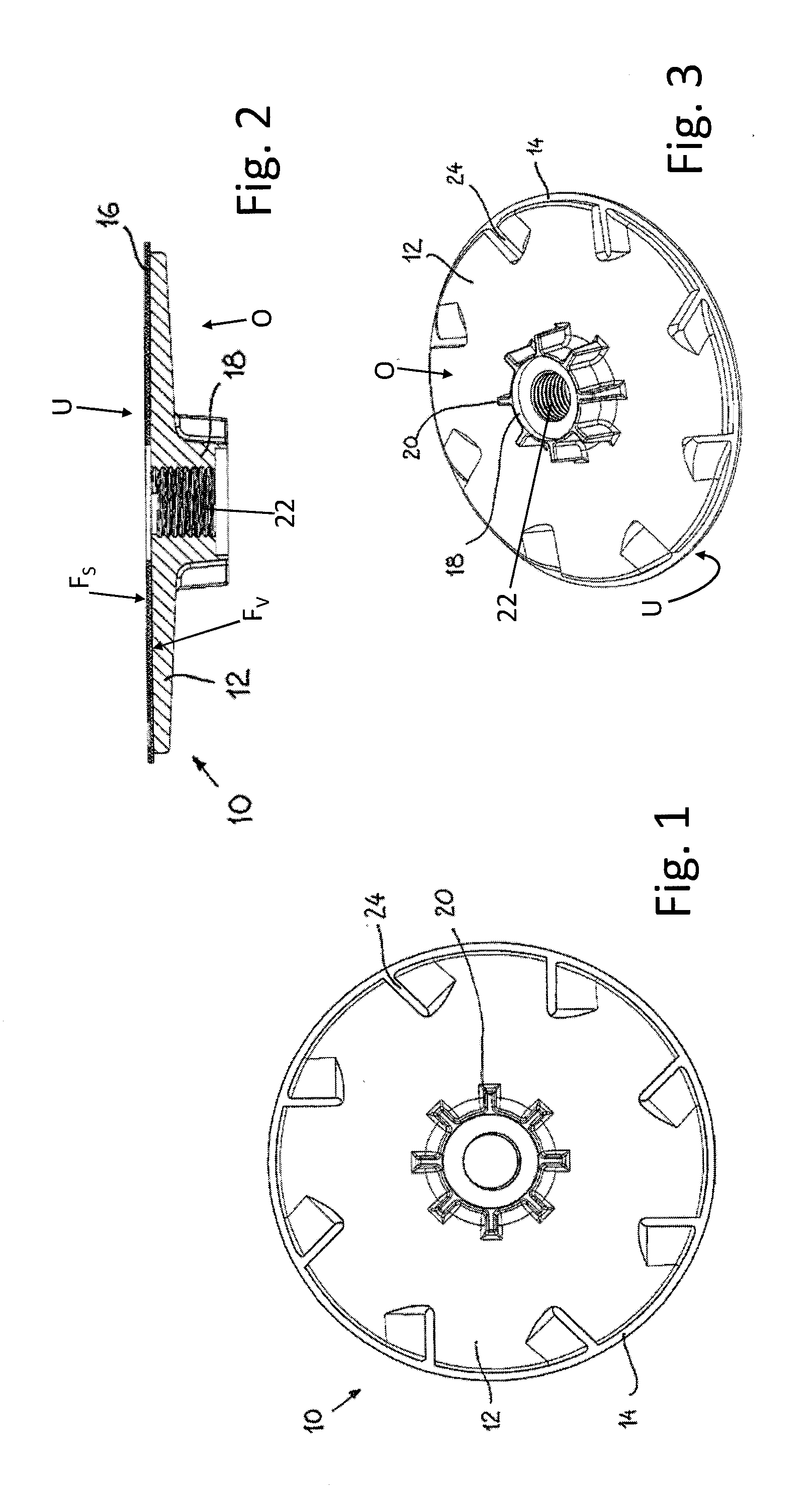
[0036] FIG. 1 shows a diagrammatic plan view of a first example of an embodiment of the grinding disc device according to the invention;
[0037] FIG. 2 shows a cross-section through the grinding disc device of FIG. 1;
[0038] FIG. 3 shows a perspective view of the grinding disc device of FIG. 1;
[0039] FIGS. 4-6 show an alternative embodiment of the grinding disc device according to the invention in plan view, in a cross-sectional representation, and in a perspective view;
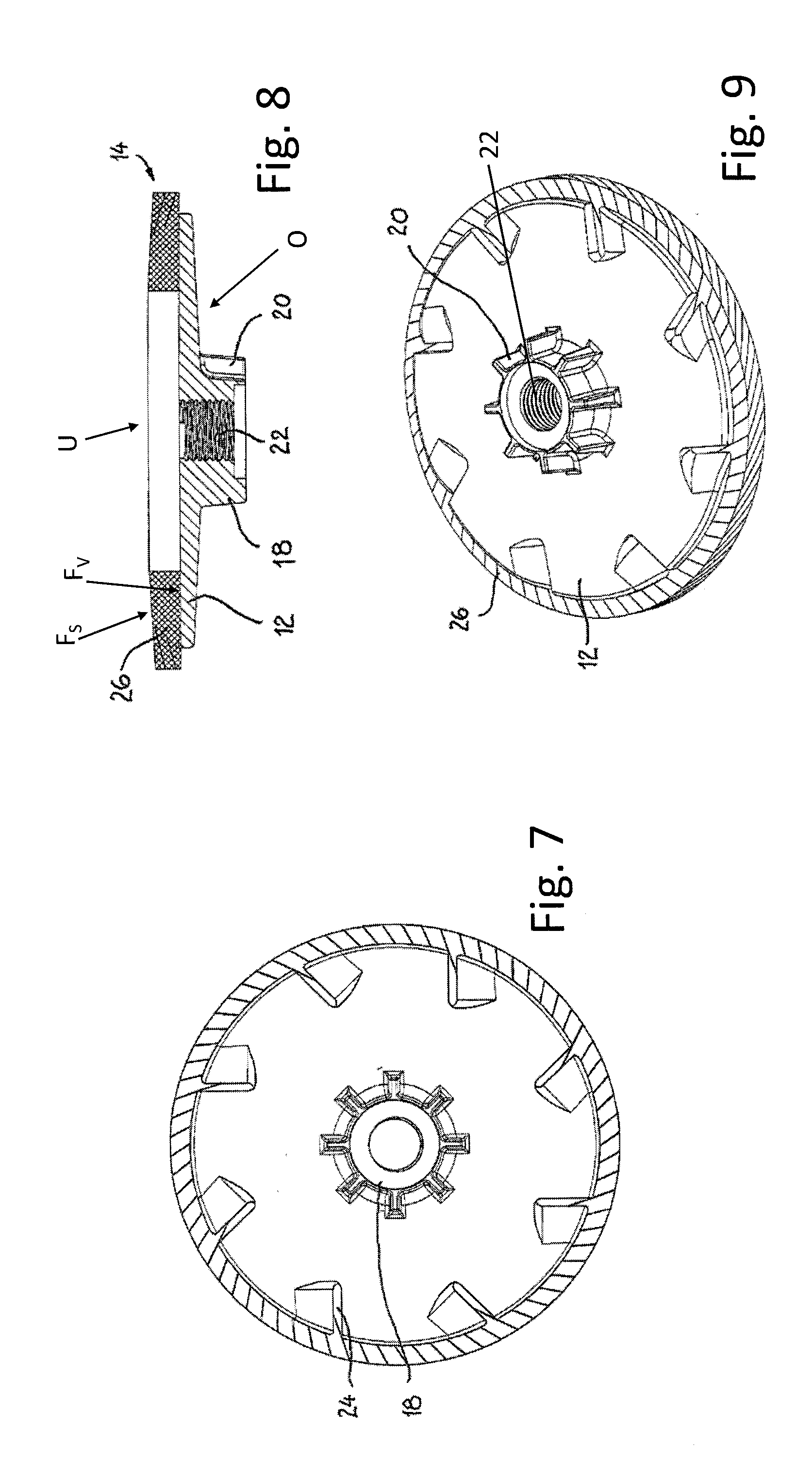
[0040] FIGS. 7-9 show a further alternative embodiment of the grinding disc device according to the invention, wherein the grinding layer comprises grinding lamellas, in plan view, in a cross-sectional representation, and in a perspective view;
[0041] FIGS. 10-12 show a further alternative embodiment of the grinding disc device according to the invention, wherein the grinding layer comprises grinding lamellas, in a view from beneath, in a cross-sectional representation, and in a perspective view from beneath;
[0042] FIGS. 13-15 show a further alternative embodiment of the grinding disc device according to the invention, wherein the grinding layer comprises grinding lamellas, in a view from beneath, in a cross-sectional representation, and in a perspective view from beneath;
[0043] FIGS. 16-18 show yet another embodiment of the grinding disc device according to the invention, in plan view, in a cross-sectional representation, and in a perspective view and
[0044] FIGS. 19-21 show yet another embodiment of the grinding disc device according to the invention, in plan view, in a cross-sectional representation, and in a perspective view.
DETAILED DESCRIPTION OF THE INVENTION
[0045] All the examples of embodiment described below have in common that grinding disc device 10, according to the invention, comprises an essentially circular carrier disc 12 provided with an abrasive grinding layer 14, such that grinding layer 14 and carrier disc 12 are immediately and directly connected to one another without an intermediate layer. The side of grinding disc device 10 on which abrasive grinding layer 14 is arranged represents an underside U of grinding disc device 10. Opposite underside U of grinding disc device 10 lies an upper side O defined by carrier disc 12.
[0046] Carrier disc 12 is produced by means of injection molding and is directly sprayed onto grinding layer 14 thereby constituting grinding disc device 10 according to the invention. Carrier disc 12 is made of plastic, for example ABS, since the material is food-safe, has a sufficient elasticity, and has a long life. Other injectable plastics can also be used for carrier disc 12. More preferably, carrier disc 12 is made of a polyamide, in particular of polyamide PA6, and even more preferably of glass fiber-reinforced polyamide with for example a 30% glass fiber content, such as for example PA6-GF30.
[0047] In injection molding, which numbers among the primary shaping processes, the plastic for carrier disc 12, for example ABS or PA6, is plasticised and injected under pressure with an injection molding machine into a shaping hollow space, i.e. the cavity of the molding tool. The plastic material transforms back into the solid state by cooling. For the production of grinding disc device 10 according to the invention, grinding layer 14 is first placed into the cavity of the molding tool prior to the injection of the plastic material, in such a way that the side of grinding layer 14 forming a grinding surface F.sub.S lies against an inner wall of the cavity and a connection surface F.sub.V of grinding layer 14 is thus facing the hollow space. The subsequent injection of the plastic material into the shaping hollow space takes place under pressure in a range from 500 bar to 2000 bar and at a temperature in a range from 200.degree. C. to 330.degree. C. The plastic material is thus sprayed directly onto connection surface F.sub.V of grinding layer 14. As a result of the hardening in the injection molding machine, the plastic material of grinding disc 12 solidifies and is directly bonded to connection surface VF of grinding layer 14 or is connected in a material-locking manner to the latter.
[0048] In the example of the embodiment of FIGS. 1 to 3, grinding layer 14, comprising a connection surface F.sub.V and a grinding surface F.sub.S, consists of a flat, circular sanding disc 16, wherein carrier disc 12 is sprayed directly by injection molding onto connection surface F.sub.V of grinding layer 14 or sanding disc 16 without plastic being applied between the two latter. This takes place by means of injection molding in a suitable injection molding machine as described above.
[0049] Grinding layer 14 is first introduced or placed into the hollow space of the molding tool. More precisely, grinding layer 14 is placed into the hollow space of the molding tool such that connection surface F.sub.V of grinding layer 14 is facing the hollow space, i.e. grinding surface F.sub.S is facing an inner wall or hollow-space wall of the molding tool and in particular lies against the latter. The plasticised plastic material of carrier disc 12 is then injected into the cavity under pressure and at raised temperature. Following a short hardening time of less than one minute, the plastic of carrier disc 12 is hard and firmly connected in a durable manner to sanding disc 16 or grinding layer 14.
[0050] In the example of the embodiment of FIG. 1 to FIG. 3, a hub part 18 is formed in one piece with carrier disc 12 at upper side O of grinding disc device 10, from which hub part ventilation ribs 20 extend radially outwards. The ventilation ribs 20 provide for a sufficient cooling air flow over the surface of carrier plate 12 at the speeds generated during operation.
[0051] As FIGS. 2 and 3 show, hub part 18 comprises an inner thread 22, which is also formed in the injection molding, so that carrier disc 12 can be fastened on a drive shaft of a grinding apparatus, in particular a grinding machine, such as for example an angle grinder.
[0052] Essentially annular grinding layer 14, which comprises a central perforation in the region of hub part 18, comprises an annular, continuous connection surface F.sub.V and an annular, continuous grinding surface F.sub.S, wherein the circular surfaces extend over more than 90% of the total area of underside U of grinding disc device 10.
[0053] For further, improved cooling, slots 24 are designed or formed distributed over the outer periphery or over upper side O of carrier disc 12. The slots 24 provide for the passage of cooling air both against connection surface F.sub.V of grinding layer 14, which can also be seen as the inner surface, as well as against the machined workpiece. Cooling air slots 24 are fashioned according to the teaching known from German Patent No. DE 10 2016 102 037 B4, which is incorporated herein by reference.
[0054] FIGS. 4 to 6 show a variant of the embodiment of FIG. 1 to FIG. 3, wherein carrier disc 12 is also sprayed directly and without adhesive onto grinding layer 14. Diverging from the example of FIG. 1 to FIG. 3, central hub part 18 is constituted with a flat dish-shaped and has ventilation ribs. In this example of the embodiment of FIGS. 4 to 6, the central perforation of grinding layer 14 in the region of hub part 18 is larger than in the example of FIGS. 1 to 3, so that the surface segment area of annular, continuous connection surface F.sub.V and grinding surface F.sub.S in the total area of underside U of grinding disc device 10 is smaller than in the example of FIGS. 1 to 3.
[0055] In the alternative, also preferred variant of FIGS. 7 to 9, grinding layer 14 comprises grinding lamellas 26 arranged fan-shaped. The plastic of carrier disc 12 is also sprayed without an intermediate adhesive onto grinding lamellas 26 arranged fan-shaped. Grinding lamellas 26 arranged fan-shaped again form a flat grinding layer 14 with connection surface F.sub.V and grinding surface F.sub.S, which are also constituted in this embodiment as respective annular, continuous surfaces on account of the overlaps of grinding lamellas 26 arranged fan-shaped.
[0056] In the embodiment of FIGS. 10 to 12, hub part 18, in the same way as in the example of the embodiment of FIGS. 4 to 6, does not have any ventilation ribs. The air slots at the outer periphery of carrier disc 12 are also absent in this example of the embodiment.
[0057] FIGS. 13 to 15 show a modified embodiment with a carrier disc 12 constituted similar to the example of FIGS. 4 to 6, wherein here, as also in the example of FIGS. 10 to 12, grinding layer 14 comprises grinding lamellas 26 arranged fan-shaped, onto which carrier disc 12 is directly sprayed.
[0058] Finally, FIGS. 16 to 18 show an embodiment with a carrier disc 12, which has cooling air slots 24 at the outer periphery for the passage of cooling air. The flat, roughly dish-shaped hub 18 of carrier disc 12 also comprises, in addition to ventilation ribs 20, cooling air passage slots 28 for the passage of cooling air. Grinding layer 14 comprises grinding lamellas 26 arranged fan-shaped.
[0059] In FIGS. 19 to 21, an example of the embodiment of grinding disc device 10 is shown, wherein grinding layer 14 is formed by a grinding disc or a sanding disc 16. The grinding disc is a vulcanised fiber disc, wherein grinding surface F.sub.S is formed by a scattered ceramic grain abrasive medium.
[0060] In the case of grinding disc device 10 of the example of FIGS. 19 to 21, hub part 18 is constituted with ventilation ribs 20 and with an inner thread 22. No cooling air slots are provided, however, in carrier disc 12.
[0061] For the additional improvement of the stability, rigidity, and bending strength, reinforcing structures are constituted on carrier disc 12 at upper side O of grinding disc device 10, and more precisely in the represented example in the form of an annular rib 30. Furthermore, an annular groove 32 is provided, which serves to improve the elasticity during grinding.
LIST OF REFERENCE NUMBERS
[0062] 10 grinding disc device [0063] 12 carrier disc [0064] 14 grinding layer [0065] 16 grinding disc or sanding disc [0066] 18 hub part [0067] 20 ventilation rib [0068] 22 inner thread [0069] 24 cooling air slots [0070] 26 grinding lamellas [0071] 28 cooling air passage slots [0072] 30 annular rib [0073] 32 annular groove [0074] F.sub.S grinding surface [0075] F.sub.V connection surface [0076] O upper side [0077] U underside
* * * * *
D00000
D00001
D00002
D00003
D00004
D00005
D00006
D00007
XML
uspto.report is an independent third-party trademark research tool that is not affiliated, endorsed, or sponsored by the United States Patent and Trademark Office (USPTO) or any other governmental organization. The information provided by uspto.report is based on publicly available data at the time of writing and is intended for informational purposes only.
While we strive to provide accurate and up-to-date information, we do not guarantee the accuracy, completeness, reliability, or suitability of the information displayed on this site. The use of this site is at your own risk. Any reliance you place on such information is therefore strictly at your own risk.
All official trademark data, including owner information, should be verified by visiting the official USPTO website at www.uspto.gov. This site is not intended to replace professional legal advice and should not be used as a substitute for consulting with a legal professional who is knowledgeable about trademark law.