Filter With Interlocking Housing Interface
KNIGHT; Jessie A. ; et al.
U.S. patent application number 16/097773 was filed with the patent office on 2019-06-06 for filter with interlocking housing interface. This patent application is currently assigned to Cummins Filtration IP, Inc.. The applicant listed for this patent is CUMMINS FILTRATION IP, INC.. Invention is credited to Robert A. BANNISTER, Jessie A. KNIGHT, Gregory K. LOKEN, Scott G. MANKE, Dane P. MILLER, Jason A. SCHERCK, Scott W. SCHWARTZ.
| Application Number | 20190168154 16/097773 |
| Document ID | / |
| Family ID | 60203314 |
| Filed Date | 2019-06-06 |


View All Diagrams
| United States Patent Application | 20190168154 |
| Kind Code | A1 |
| KNIGHT; Jessie A. ; et al. | June 6, 2019 |
FILTER WITH INTERLOCKING HOUSING INTERFACE
Abstract
A filter element includes first filter media, second filter media, a frame, and a seal member. The frame is coupled to the first filter media and the second filter media, the frame securing the first filter media and the second filter media into a V-shape. The seal member is attached to and extends from the frame. The seal member includes a U-shaped channel structured to receive a ridge of a housing when the filter element is installed in the housing. The seal member is structured to form a seal between the filter element and the housing when the filter element is installed in the housing.
| Inventors: | KNIGHT; Jessie A.; (Oregon, WI) ; MANKE; Scott G.; (Sun Prairie, WI) ; MILLER; Dane P.; (Madison, WI) ; SCHERCK; Jason A.; (Madison, WI) ; BANNISTER; Robert A.; (Ames, IA) ; LOKEN; Gregory K.; (Stoughton, WI) ; SCHWARTZ; Scott W.; (Cottage Grove, WI) | ||||||||||
| Applicant: |
|
||||||||||
|---|---|---|---|---|---|---|---|---|---|---|---|
| Assignee: | Cummins Filtration IP, Inc. Columbus IN |
||||||||||
| Family ID: | 60203314 | ||||||||||
| Appl. No.: | 16/097773 | ||||||||||
| Filed: | May 1, 2017 | ||||||||||
| PCT Filed: | May 1, 2017 | ||||||||||
| PCT NO: | PCT/US2017/030386 | ||||||||||
| 371 Date: | October 30, 2018 |
Related U.S. Patent Documents
| Application Number | Filing Date | Patent Number | ||
|---|---|---|---|---|
| 62330310 | May 2, 2016 | |||
| Current U.S. Class: | 1/1 |
| Current CPC Class: | B01D 2279/60 20130101; F02M 35/02416 20130101; B01D 2271/027 20130101; F02M 35/02491 20130101; F02M 35/0202 20130101; B01D 46/0005 20130101; B01D 2271/022 20130101; B01D 46/125 20130101; F02M 35/0201 20130101; F02M 35/02425 20130101 |
| International Class: | B01D 46/12 20060101 B01D046/12; B01D 46/00 20060101 B01D046/00; F02M 35/02 20060101 F02M035/02; F02M 35/024 20060101 F02M035/024 |
Claims
1. A filter element comprising: first filter media; second filter media; a frame coupled to the first filter media and the second filter media; and a seal member attached to and extending from the frame, the seal member including a U-shaped channel structured to receive a ridge of a housing when the filter element is installed in the housing, the seal member structured to form a seal between the filter element and the housing when the filter element is installed in the housing.
2. The filter element of claim 1, wherein the frame secures the first filter media and the second filter media into a V-shape; and wherein the frame comprises: a first frame member coupled to a first end of the first filter media and a first end of the second filter media; and a second frame member coupled to a second end of the first filter media, opposite the first end of the first filter media, and a second end of the second filter media, opposite the first end of the second filter media.
3. The filter element of claim 2, wherein the frame further comprises: a first side wall positioned along a first side of the first filter media and a first side of the second filter media, the first side wall coupled to the first frame member and the second frame member; and a second side wall positioned along a second side of the first filter media, opposite the first side of the first filter media, and a second side of the second filter media, opposite the first side of the second filter media.
4. The filter element of claim 3, wherein the first side wall is disposed along a first plane and the second side wall is disposed along a second plane; the first plane substantially parallel to the second plane.
5. The filter element of claim 4, wherein the first side wall and the second side wall are both trapezoidal in shape.
6. The filter element of claim 3, wherein the first filter media and the second filter media are contained within the frame.
7. The filter element of claim 3, wherein the first frame member is defined by a first perimeter; wherein the second frame member is defined by a second perimeter less than the first perimeter; and wherein the seal member is attached to, and extends from, the first frame member.
8. The filter element of claim 7, wherein the filter element is oriented within the housing such that air enters the filter element through the first frame member.
9. The filter element of claim 7, wherein the filter element is oriented within the housing such that air enters the filter element through the second frame member.
10. The filter element of claim 3, wherein the first filter media and the second filter media are potted into the first side wall; and wherein the first filter media and the second filter media are potted into the second side wall.
11. A filtration system comprising: a housing comprising a keyway; and a filter element positioned within the housing, the filter element comprising: first filter media; second filter media; and a frame coupled to the first filter media and the second filter media; wherein the keyway interfaces with the filter element to facilitate positioning of the filter element within the housing.
12. The filtration system of claim 11, wherein the filter element further comprises a seal member attached to and extending from the frame, the seal member including a U-shaped channel structured to receive a ridge of the housing.
13. The filtration system of claim 12, further comprising a cover removably coupled to the housing, the cover configured to selectively cover the filter element within the housing, the cover compressing the seal member such that a seal is formed between the filter element, the housing, and the cover.
14. The filtration system of claim 11, wherein the frame secures the first filter media and the second filter media into a V-shape; and wherein the frame comprises: a first frame member coupled to a first end of the first filter media and a first end of the second filter media; and a second frame member coupled to a second end of the first filter media, opposite the first end of the first filter media, and a second end of the second filter media, opposite the first end of the second filter media.
15. The filtration system of claim 14, wherein the frame further comprises: a first side wall positioned along a first side of the first filter media and a first side of the second filter media, the first side wall coupled to the first frame member and the second frame member, the first side wall having a V-shape contour; and a second side wall positioned along a second side of the first filter media, opposite the first side of the first filter media, and a second side of the second filter media, opposite the first side of the second filter media, the second side wall having a V-shape contour.
16. The filtration system of claim 15, wherein the housing further comprises: a first side-support keyway that interfaces with the first side wall to support the first side wall within the housing, the first side-support keyway being angled to match the V-shape contour of the first side wall; and a second side-support keyway that interfaces with the second side wall to support the second side wall within the housing, the second side-support keyway being angled to match the V-shape contour of the second side wall.
17. A filter element comprising: first filter media; second filter media; and a frame coupled to the first filter media and the second filter media, the frame securing the first filter media and the second filter media, the frame comprising: a first frame member coupled to a first end of the first filter media and a first end of the second filter media; a second frame member coupled to a second end of the first filter media, opposite the first end of the first filter media, and a second end of the second filter media, opposite the first end of the second filter media; a first side wall positioned along a first side of the first filter media and a first side of the second filter media, the first side wall coupled to the first frame member and the second frame member; and a second side wall positioned along a second side of the first filter media, opposite the first side of the first filter media, and a second side of the second filter media, opposite the first side of the second filter media.
18. The filter element of claim 17, wherein the first side wall is disposed along a first plane and the second side wall is disposed along a second plane; the first plane substantially parallel to the second plane.
19. The filter element of claim 17, wherein the first side wall and the second side wall are both trapezoidal in shape.
20. The filter element of claim 17, wherein the first filter media and the second filter media are contained within the frame.
21. The filter element of claim 17, further comprising a seal member; wherein the first frame member is defined by a first perimeter; wherein the second frame member is defined by a second perimeter less than the first perimeter; and wherein the seal member is attached to, and extends from, the first frame member.
22. The filter element of claim 21, wherein the filter element is oriented such that air enters the filter element through the first frame member and at least partially exits the filter element through the second frame member.
23. The filter element of claim 21, wherein the filter element is oriented such that air enters the filter element through the second frame member and at least partially exits the filter element through the first frame member.
24. The filter element of claim 17, wherein the first filter media and the second filter media are potted into the first side wall; and wherein the first filter media and the second filter media are potted into the second side wall.
25. The filter element of claim 17, wherein the frame secures the first filter media and the second filter media into a V-shape.
Description
CROSS-REFERENCE TO RELATED PATENT APPLICATION
[0001] The present application claims the benefit of priority to U.S. Provisional Patent Application No. 62/330,310, filed May 2, 2016, the contents of which are incorporated herein by reference in its entirety.
TECHNICAL FIELD
[0002] The present application relates to filter elements for use with filtration systems.
BACKGROUND
[0003] Internal combustion engines generally combust a mixture of fuel (e.g., gasoline, diesel, natural gas, etc.) and air. Prior to entering the engine, intake air is typically passed through a filter element to remove contaminants (e.g., particulates, dust, water, etc.) from the intake air prior to delivery to the engine. The filter element requires periodic replacement as the filter media of the filter element captures and removes particulate from the intake air passing through the filter media. Accordingly, the filter element is typically removably received in the housing such that when the filter element is installed, a seal is formed between the filter element and the housing preventing bypass of the intake air around the filter element. The use of a non-authorized filter element in a filtration system may lead to a poor seal or no seal thereby allowing intake air to bypass the filter element, which can damage the internal combustion engine.
SUMMARY
[0004] Various example embodiments relate to filter elements. One such filter element includes first filter media and second filter media. The filter element further includes a frame member coupled to the first filter media and the second filter media. The frame member secures the first filter media and the second filter media (such as into a V-shape). The filter element includes a seal member is attached to and extends from the frame member. The seal member includes a U-shaped channel structured to receive a ridge of a housing when the filter element is installed in the housing. The seal member is structured to form a seal between the filter element and the housing when the filter element is installed in the housing.
[0005] In an embodiment, a filter element includes first filter media, second filter media, a frame, and a seal member. The frame is coupled to the first filter media and the second filter media, the frame securing the first filter media and the second filter media. The seal member is attached to and extends from the frame. The seal member includes a U-shaped channel structured to receive a ridge of a housing when the filter element is installed in the housing. The seal member is structured to form a seal between the filter element and the housing when the filter element is installed in the housing.
[0006] In another embodiment, a filtration system includes a housing and a filter element. The housing includes a keyway. The filter element is positioned within the housing. The filter element includes first filter media, second filter media, and a frame. The frame is coupled to the first filter media and the second filter media. The frame secures the first filter media and the second filter media. The keyway interfaces with the filter element to facilitate positioning of the filter element within the housing.
[0007] In still another embodiment, a filter element includes first filter media, second filter media, and a frame. The frame is coupled to the first filter media and the second filter media. The frame secures the first filter media and the second filter media. The frame includes a first frame member, a second frame member, a first side wall, and a second side wall. The first frame member is coupled to a first end of the first filter media and a first end of the second filter media. The second frame member is coupled to a second end of the first filter media, opposite the first end of the first filter media, and a second end of the second filter media, opposite the first end of the second filter media. The first side wall is positioned along a first side of the first filter media and a first side of the second filter media. The first side wall is coupled to the first frame member and the second frame member. The second side wall is positioned along a second side of the first filter media, opposite the first side of the first filter media, and a second side of the second filter media, opposite the first side of the second filter media.
[0008] These and other features, together with the organization and manner of operation thereof, will become apparent from the following detailed description when taken in conjunction with the accompanying drawings, wherein like elements have like numerals throughout the several drawings described below.
BRIEF DESCRIPTION OF THE FIGURES
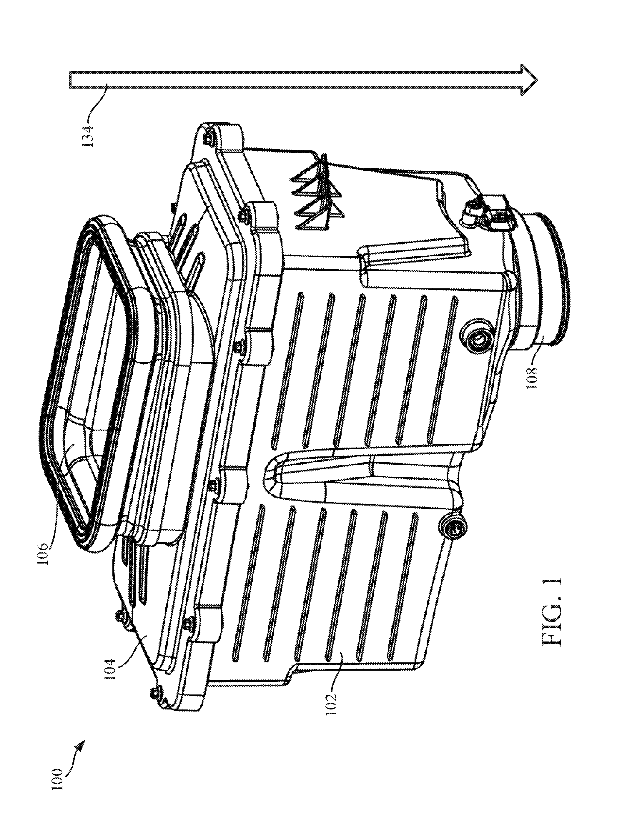
[0009] FIG. 1 shows a perspective view of a filtration system according to an example embodiment.
[0010] FIG. 2 shows a cross-sectional view of the filtration system of FIG. 1.
[0011] FIG. 3 shows another cross-sectional view of the filtration system of FIG. 1.
[0012] FIG. 4 shows an exploded view of the filtration system of FIG. 1.
[0013] FIG. 5 shows a perspective view of the filter element of the filtration system of FIG. 1.
[0014] FIGS. 6, 7, 8, 9, 10, 11, and 12 each show a different close-up view of the filter element of the filtration system of FIG. 1.
[0015] FIG. 13 shows a cross-sectional view of the filter element installed in the housing of the filtration system of FIG. 1.
[0016] FIG. 14 shows another cross-sectional view of the filter element installed in the housing of the filtration system of FIG. 1.
[0017] FIGS. 15 and 16 each show a cross-sectional view of a filtration system having the air flow direction reversed compared to the filtration system of FIG. 1.
[0018] FIG. 17 shows an exploded view of the filter element of the filtration system of FIG. 1.
[0019] FIG. 18 shows a cross-sectional view of the filter element of the filtration system of FIG. 1.
[0020] FIG. 19 shows a top view of a first frame of the filter element of the filtration system of FIG. 1.
[0021] FIG. 20 shows a top view of a second frame of the filter element of the filtration system of FIG. 1.
[0022] FIG. 21 shows a perspective view of the second frame of FIG. 20.
[0023] FIG. 22 shows an exploded view of the filter element of the filtration system of FIG. 1 during manufacturing.
[0024] FIG. 23 shows another exploded view of the filter element of the filtration system of FIG. 1 during manufacturing.
[0025] FIG. 24 shows a perspective view of the filter element of the filtration system of FIG. 1 during manufacturing.
[0026] FIG. 25 shows an exploded view of the filter element of the filtration system of FIG. 1 during manufacturing.
DETAILED DESCRIPTION
[0027] Referring to the figures generally, a filtration system having a filter element removably received in a housing is shown. In some arrangements, the filter element includes two panel filters coupled to a frame that secure the panel filters in a V-shape such that a cross-section of the filter element has a V-shape. In other arrangements, the filter element includes filter media arranged in an alternate shape, such as a rectangular panel, a cylindrical shape, or the like. The filter media comprising the filter element may be pleated or non-pleated. The filter element includes a seal having an alignment channel. The housing includes an alignment rib that is received in the alignment channel of the filter element when the filter element is installed in the housing. A cover is removably secured to the housing. When the cover is secured to the housing and the filter element is installed in the housing, the cover compresses the seal member against the housing forming an axial seal between the housing and the filter element. In some arrangements, the seal member does not form a radial seal against the housing. In other arrangements, the seal member forms only a radial seal or a combination of a radial and axial seal.
[0028] Referring to FIG. 1, a perspective view of a filtration system 100 is shown according to an example embodiment. Referring to FIG. 2 and FIG. 3, cross-sectional views of the filtration system 100 are shown. Referring to FIG. 4, an exploded view of the filtration system 100 is shown. The filtration system 100 includes a housing 102 and a cover 104. The cover 104 is removably coupled to the housing 102. The cover 104 may be removably coupled to the housing 102 through fasteners (e.g., screws), clamps, snap fit connections, or a combination thereof. The cover includes an air inlet 106 structured to provide air to be filtered to the filtration system 100. The housing 102 includes an air outlet 108 structured to provide filtered air to a component, such as an internal combustion engine. As shown best in FIGS. 2 through 4, a filter element 110 is removably received within the housing 102 and the cover 104. The filter element 110 has a V-shaped cross section (as shown in FIG. 2).
[0029] Referring to FIGS. 5-12, various views of the filter element 110 of the filtration system 100 are shown. The filter element 110 includes first filter media 112 and second filter media 114. In some arrangements, the first filter media 112 and the second filter media 114 are panel filters that form the filter element 110. The first filter media 112 and the second filter media 114 may be the same type of filter media or different filter media. In some arrangements, the first filter media 112 and the second filter media 114 are pleated filter blocks as described in U.S. Pat. No. 6,375,700, entitled "DIRECT FLOW FILTER," which is herein incorporated by reference in its entirety and for all purposes. In some arrangements, the pleat tips of the first and second filter media 112 and 114 are blocked on one end and open on the other end. In other arrangements, the pleat tips are blocked on both ends.
[0030] The filter element 110 includes a frame comprising a first frame member 116 and a second frame member 118. The first frame member 116 and the second frame member 118 secure the first filter media 112 and the second filter media 114 into a V-shape (e.g., as shown in FIG. 2). The first frame member 116 and the second frame member 118 provide durability and structure to the filter element 110 and serve as manufacturing fixtures during manufacturing of the filter element 110. The first frame member 116 and the second frame member 118 protect the first and second filter media 112 and 114 during manufacturing and during installation of the filter element 110 into the housing 102. As shown best in FIG. 12, the second frame member 118 wraps around the edge of the first and second filter media 112 and 114 limiting the exposure of the first and second filter media 112 and 114 to come in contact with other objects (e.g., the housing 102 during installation of the filter element 110). The rigidity created by the first and second frames 116 and 118 also improve the aesthetics and durability of the filter element 110. The rigidity helps to prevent the first filter media 112 and the second filter media 114 from collapsing during use and limits the stress on the first filter media 112 and the second filter media 114 during sealing (as described below with respect to the seal member 124). Further the first and second frames 116 and 118 provide a grip area for a technician installing the filter element 110 into the housing 102 or removing an installed filter element 110 from the housing 102.
[0031] The first filter media 112 and the second filter media 114 may include any of pleated media, corrugated media, tetrahedral media, or variations thereof. U.S. Pat. No. 8,397,920, entitled "PLEATED FILTER ELEMENT WITH TAPERING BEND LINES," by Moy et al., filed on Oct. 14, 2011, and issued on Mar. 19, 2013, assigned to Cummins Filtration IP Inc., which is incorporated by reference in its entirety and for all purposes, describes a tetrahedral filter media. Some configurations of tetrahedral filter media include a plurality of inlet tetrahedron flow channels and a plurality of outlet tetrahedron flow channels. The inlet tetrahedron merge in a central portion of the filter material, thereby allowing axial cross-flow of air between the inlet tetrahedron channels prior to the air passing through the filter media. Such an arrangement provides for additional dust loading on the upstream side of the media, which increases filter capacity. The tetrahedral flow channels may be stacked, layered, or coiled into various shapes and configurations. For example, the first and second filter media 112 and 114 may have, for example, thirty to eighty stacked layers of tetrahedral flow channels. These stacked layers of tetrahedral flow channels can be arranged to form various shapes. For example, layers of tetrahedral flow channels, the layers having different lengths and/or widths, can be stacked such that the stacked layers of tetrahedral flow channels substantially match the V-shape of the filter element 110 as shown and described. Specific arrangements of such tetrahedral filter media are further described in U.S. Pat. No. 8,397,920.
[0032] The filter element 110 includes side walls 120. In some arrangements, the side walls 120 are comprised of urethane. Alternatively, the side walls 120 be comprised of plastisol. In such arrangements, the first filter media 112 and the second filter media 114 may be potted into or overmolded into the side walls 120. For example, a face of a first pleat within the first filter media 112 and a face of a first plate within the second filter media 114 may be potted into one of the side walls 120, and a face of a second pleat within the first filter media 112 and a face of a second plate within the second filter media 114 may be potted into the other of the side walls 120.
[0033] In some arrangements, the side walls 120 each have a trapezoidal shape. In some arrangements, the side walls 120 include a flat surface for receiving a label (e.g., a product label or identifier). The outer perimeter thickness of the side walls 120 is controlled during manufacturing by using a closed mold, which allows for a controlled surface with which to engage during additional manufacturing operations. Additionally, the first and second frames 116 and 118 include urethane shut-off ridges 122 that prevent the urethane forming the side walls 120 from over-expanding and blow (as shown in FIGS. 6, 7, and 10). The tapered shape of the filter element 110 allows for improved filter alignment and serviceability.
[0034] The filter element 110 includes a seal member 124. As shown in FIG. 3, when the filter element 110 is installed in the housing 102, the seal member 124 is compressed by the cover 104 against the housing 102 and forms an axial seal with the housing 102. In some arrangements, the seal member 124 is urethane. In such arrangements, the seal member 124 may be overmolded over the first frame member 116 and the side walls 120. The axial seal prevents air entering the filtration system 100 through the inlet 106 from bypassing the filter element 110. As shown in FIGS. 5, 7, and 8, the seal member 124 includes a U-shaped channel 126. The U-shaped channel 126 receives a ridge of the housing 102 (as shown in FIG. 3). The interaction between the U-shaped channel 126 and the ridge helps to align the filter element 110 during installation of the filter element 110 into the housing 102. During installation, when the cover 104 is secured to the housing 102, a ridge 128 on the cover 104 presses into the seal member 124 to help form the axial seal.
[0035] In some arrangements, the seal member 124 does not include a U-shaped channel. According to some embodiments, the seal member 124 has a stepped geometry. In these embodiments, the seal member 124 may provide multiple sealing faces that interface with the cover 104. The top and/or bottom of the seal member 124 may be stepped in this fashion such that the seal member 124 may be tailored for a target application.
[0036] Referring again to FIG. 4, the housing 102 includes a keyway 130 that receives and guides the filter element 110 during installation of the filter element into the housing 102. The keyway allows the filter element 110 and the housing 102 to nest together. The keyway 130 is structured to function as a support surface that generally limits the amount of movement of the filter element 110 within the housing, thereby limiting the strain on the filter element 110 caused by vibration or heavy loading on the filter element 110 during operation of the filtration system 100. The keyway 130 also prevents the filter element 110 from sagging during horizontal configurations of the filter element. In some arrangements, the keyway 130 is angled to match the angle of the V-shape of the filter element 110. In further arrangements, the keyway 130 includes an internal rib that provides a positive stop to limit movement of the filter element 110 during installation. In some arrangements, the housing also includes a side-support keyway 132 that supports the side of the filter element 110 within the housing 102 (e.g., as shown in FIG. 4). In such arrangements, the side-support keyway 132 is angled to match the V-shaped contour of the side walls 120 of the filter element 110. The interaction of the filter element 110 with the keyway 130 and the side-support keyway 132 are shown in FIGS. 13 and 14.
[0037] During operation of the filtration system 100, air to be filtered enters in through the inlet 106 and passes into the central area of the V-shape formed between the first filter media 112 and the second filter media 114 through the supports of the first frame member 116. The air then passes through the first filter media 112 and the second filter media 114, where the first filter media 112 and the second filter media 114 removes and captures contaminants in the air (e.g., dust, dirt, moisture, etc.). The filtered air then exits the housing 102 through the outlet 108. Accordingly, the air flows in a general air flow direction designated by arrow 134 of FIG. 1. When the filter element 110 is replaced, the V-shaped pocket formed between the first filter media 112, the second filter media 114, and the two side walls 120 contains all of the captured contaminants thereby resulting in a clean filter cartridge service. In an alternative arrangement, the filtration system 100 is structured to have airflow move in the opposite direction. Such an arrangement is shown in FIGS. 15 and 16. In such an arrangement, the cover 104 may be fitted with an outlet hood 136. In either arrangement, the cover 104 can be formed to receive and/or distribute the air directly from the open area between the first filter media 112 and the second filter media 114 thereby improving the flow characteristics of the system.
[0038] FIGS. 17 through 25 show additional views of the filtration system 100 and its components. As shown specifically in FIG. 17, the second frame member 118 may receive a single urethane seal. In this way, a de-molding operation may not be required when assembling filter element 110. The single urethane seal may contact both the first filter media 112 and the second filter media 114.
[0039] It should be noted that any use of the term "example" herein to describe various embodiments is intended to indicate that such embodiments are possible examples, representations, and/or illustrations of possible embodiments (and such term is not intended to connote that such embodiments are necessarily extraordinary or superlative examples).
[0040] References herein to the positions of elements (e.g., "top," "bottom," "above," "below," etc.) are merely used to describe the orientation of various elements in the FIGURES. It should be noted that the orientation of various elements may differ according to other example embodiments, and that such variations are intended to be encompassed by the present disclosure.
[0041] The terms "coupled" and the like as used herein mean the joining of two members directly or indirectly to one another. Such joining may be stationary (e.g., permanent) or moveable (e.g., removable or releasable). Such joining may be achieved with the two members or the two members and any additional intermediate members being integrally formed as a single unitary body with one another or with the two members or the two members and any additional intermediate members being attached to one another.
[0042] It is important to note that the construction and arrangement of the various example embodiments are illustrative only. Although only a few embodiments have been described in detail in this disclosure, those skilled in the art who review this disclosure will readily appreciate that many modifications are possible (e.g., variations in sizes, dimensions, structures, shapes and proportions of the various elements, values of parameters, mounting arrangements, use of materials, colors, orientations, etc.) without materially departing from the novel teachings and advantages of the subject matter described herein. For example, elements shown as integrally formed may be constructed of multiple parts or elements, the position of elements may be reversed or otherwise varied, and the nature or number of discrete elements or positions may be altered or varied. The order or sequence of any process or method steps may be varied or re-sequenced according to alternative embodiments. Additionally, features from particular embodiments may be combined with features from other embodiments as would be understood by one of ordinary skill in the art. Other substitutions, modifications, changes and omissions may also be made in the design, operating conditions and arrangement of the various example embodiments without departing from the scope of the present invention.
* * * * *
D00000
D00001
D00002
D00003
D00004
D00005
D00006
D00007
D00008
D00009
D00010
D00011
D00012

D00013

XML
uspto.report is an independent third-party trademark research tool that is not affiliated, endorsed, or sponsored by the United States Patent and Trademark Office (USPTO) or any other governmental organization. The information provided by uspto.report is based on publicly available data at the time of writing and is intended for informational purposes only.
While we strive to provide accurate and up-to-date information, we do not guarantee the accuracy, completeness, reliability, or suitability of the information displayed on this site. The use of this site is at your own risk. Any reliance you place on such information is therefore strictly at your own risk.
All official trademark data, including owner information, should be verified by visiting the official USPTO website at www.uspto.gov. This site is not intended to replace professional legal advice and should not be used as a substitute for consulting with a legal professional who is knowledgeable about trademark law.