Athletic Gear Or Other Devices Comprising Pads Or Other Cushioning Components
LAPERRI RE; JEAN-FRAN OIS ; et al.
U.S. patent application number 16/206112 was filed with the patent office on 2019-06-06 for athletic gear or other devices comprising pads or other cushioning components. The applicant listed for this patent is BAUER HOCKEY LTD.. Invention is credited to CHARLES-ANTOINE DESROCHERS, JEAN-FRAN OIS LAPERRI RE.
| Application Number | 20190166947 16/206112 |
| Document ID | / |
| Family ID | 66657464 |
| Filed Date | 2019-06-06 |


View All Diagrams
| United States Patent Application | 20190166947 |
| Kind Code | A1 |
| LAPERRI RE; JEAN-FRAN OIS ; et al. | June 6, 2019 |
ATHLETIC GEAR OR OTHER DEVICES COMPRISING PADS OR OTHER CUSHIONING COMPONENTS
Abstract
A device (e.g., an article of athletic gear) comprising a cushioning component for absorbing energy when the device is contacted (i.e., impacted or otherwise contacted), in which the cushioning component comprises a core comprising a plurality of zones of different materials (e.g., which may differ in one or more materials properties such as density, stiffness, resilience, etc.) and a covering disposed on the core. In some embodiments, a given one of the zones of different materials may be a zone of expanded microspheres. The cushioning component may provide enhanced protection, comfort, and/or vibration or other shock absorption while being relatively lightweight.
| Inventors: | LAPERRI RE; JEAN-FRAN OIS; (PREVOST, CA) ; DESROCHERS; CHARLES-ANTOINE; (PREVOST, CA) | ||||||||||
| Applicant: |
|
||||||||||
|---|---|---|---|---|---|---|---|---|---|---|---|
| Family ID: | 66657464 | ||||||||||
| Appl. No.: | 16/206112 | ||||||||||
| Filed: | November 30, 2018 |
Related U.S. Patent Documents
| Application Number | Filing Date | Patent Number | ||
|---|---|---|---|---|
| 62592853 | Nov 30, 2017 | |||
| Current U.S. Class: | 1/1 |
| Current CPC Class: | B32B 2307/72 20130101; A63B 2102/18 20151001; A42B 3/128 20130101; A43B 5/1625 20130101; A63B 2209/02 20130101; A63B 2071/1208 20130101; B32B 1/00 20130101; A42B 3/08 20130101; A63B 59/70 20151001; A63B 2102/14 20151001; A42B 3/06 20130101; A63B 59/54 20151001; A63B 2209/00 20130101; B32B 2307/51 20130101; A63B 2102/24 20151001; A63B 71/14 20130101; A42B 3/324 20130101; B32B 2571/00 20130101; A43B 23/028 20130101; A63B 71/10 20130101; A63B 71/141 20130101; A43B 5/00 20130101; A63B 59/20 20151001; A63B 71/12 20130101; A63B 71/1225 20130101; B32B 2307/558 20130101; B32B 27/065 20130101; A63B 60/08 20151001; A42B 3/121 20130101; B32B 2437/04 20130101 |
| International Class: | A42B 3/12 20060101 A42B003/12 |
Claims
1. A cushioning component comprising: a core comprising a plurality of zones of different materials; and a covering disposed on the core; wherein a given one of the zones of different materials is a zone of expanded microspheres.
2. The cushioning component of claim 1, wherein a density of a first zone of the different materials is different from a density of a second one of the zones of different materials.
3. The cushioning component of claim 2, wherein the cushioning component is configured to protect a user, the second one of the zone of different materials is configured to be located closer to the user than the first one of the zones of different materials, and the density of the second one of the zones of different materials is less than the density of the first one of the zones of different materials.
4. (canceled)
5. The cushioning component of claim 2, wherein the density of the second one of the zones of different materials is no more than 50% of the density of the first one of the zones of different materials.
6. (canceled)
7. The cushioning component of claim 2, wherein a modulus of elasticity of a first zone of the different materials is different from a modulus of elasticity of a second one of the zones of different materials.
8. (canceled)
9. (canceled)
10. (canceled)
11. (canceled)
12. The cushioning component of claim 1, wherein a resilience of a first zone of the different materials is different from a resilience of a second one of the zones of different materials.
13. (canceled)
14. (canceled)
15. (canceled)
16. (canceled)
17. The cushioning component of claim 1, wherein an elongation at break of a first zone of the different materials is different from an elongation at break of a second one of the zones of different materials.
18. (canceled)
19. (canceled)
20. (canceled)
21. (canceled)
22. The cushioning component of claim 1, wherein the given one of the zones of different materials is a first given one of the zones of different materials, the zone of expanded microspheres is a first zone of expanded microspheres, a second given one of the zones of different materials is a second zone of expanded microspheres, and a density of the first zone of expanded microspheres is different from a density of the second zone of expanded microspheres.
23. The cushioning component of claim 22, wherein the cushioning component is configured to protect a user, the second zone of expanded microspheres is configured to be located closer to the user than the first zone of expanded microspheres, and the density of the second zone of expanded microspheres is less than the density of the first zone of expanded microspheres.
24. (canceled)
25. (canceled)
26. (canceled)
27. The cushioning component of claim 1, wherein the zone of expanded microspheres constitutes at least one-quarter of the core by weight.
28. (canceled)
29. The cushioning component of claim 1, wherein the zone of expanded microspheres constitutes at least half of the core by weight.
30. The cushioning component of claim 1, wherein the given one of the zones of different materials is a first given one of the zones of different materials, the zone of expanded microspheres is a first zone of expanded microspheres, and a second given one of the zones of different materials is a second zone of expanded microspheres.
31. The cushioning component of claim 30, wherein a state of the first zone of expanded microspheres is different from a state of the second zone of expanded microspheres.
32. The cushioning component of claim 30, wherein the first zone of expanded microspheres is consolidated and the second zone of expanded microspheres is unconsolidated.
33. The cushioning component of claim 1, wherein expanded microspheres constitute at least one-quarter of the core by weight.
34. (canceled)
35. The cushioning component of claim 1, wherein expanded microspheres constitute at least a majority of the core by weight.
36. The cushioning component of claim 1, wherein the given one of the zones of different materials is a first given one of the zones of different materials, and a second given one of the zones of different materials is not a zone of expanded microspheres.
37. The cushioning component of claim 1, wherein: the given one of the zones of different materials is a first given one of the zones of different materials; and a second given one of the zones of different materials is a zone of foam.
38. The cushioning component of claim 37, wherein the zone of foam is a first zone of foam, a third given one of the zones of different materials is a second zone of foam, and a density of the second zone of foam is different from a density of the second zone of foam.
39. (canceled)
40. (canceled)
41. (canceled)
42. The cushioning component of claim 1, wherein the zones of different materials include at least three zones of different materials.
43. The cushioning component of claim 1, wherein a peripheral one of the zones of different materials comprises a projection projecting from an adjacent part of a surface of the core.
44. The cushioning component of claim 1, wherein a peripheral one of the zones of different materials comprises a plurality of projections projecting from an adjacent part of a surface of the core and spaced from one another.
45. The cushioning component of claim 1, wherein a thickness of the zone of expanded microspheres corresponds to at least one-quarter of a thickness of the core.
46. (canceled)
47. The cushioning component of claim 1, wherein a thickness of the zone of expanded microspheres corresponds to at least a majority of a thickness of the core.
48. (canceled)
49. (canceled)
50. The cushioning component of claim 1, wherein a particular one of the zones of different materials and an adjacent one of the zones of different materials are interlocked by an interlocking part of the particular one of the zones of different materials extending into an interlocking void of the adjacent one of the zones of different materials.
51. The cushioning component of claim 1, wherein the core comprises a first side and a second side opposite to the first side of the core and the first side of the core is uneven.
52. The cushioning component of claim 1, wherein the first side of the core is concave.
53. The cushioning component of claim 1, wherein the core comprises a first side and a second side opposite to the first side of the core and the covering covers at least part of the first side of the core and at least part of the second side of the core.
54. The cushioning component of claim 53, wherein the covering covers at least a majority of the first side of the core and at least a majority of the second side of the core.
55. The cushioning component of claim 54, wherein the covering covers an entirety of the first side of the core and an entirety of the second side of the core.
56. The cushioning component of claim 1, wherein the covering covers at least a majority of a periphery of the core.
57. The cushioning component of claim 1, wherein the covering envelops the core.
58. The cushioning component of claim 1, wherein the covering is molded to conform to the core.
59. The cushioning component of claim 58, wherein at least part of the covering is vacuum-formed.
60. The cushioning component of claim 1, wherein the covering comprises a layer of polymeric material molded to conform to the core.
61. The cushioning component of claim 60, wherein the layer of polymeric material is a layer of polyurethane.
62. The cushioning component of claim 1, wherein the covering comprises a layer of fabric molded to conform to the core.
63. The cushioning component of claim 1, wherein the covering comprises a layer of a first material molded to conform to a first side of the core and a layer of a second material different from the first material molded to conform to a second side of the core opposite to the first side of the core.
64. The cushioning component of claim 1, wherein the first material is a polymeric material and the second material is a fabric.
65. The cushioning component of claim 1, wherein the covering is bonded to the core.
66. (canceled)
67. (canceled)
68. (canceled)
69. (canceled)
70. (canceled)
71. The cushioning component of claim 1, wherein the core comprises a hole extending through the core and defined by an internal surface of the core, and the covering extends into the hole and covers at least part of the internal surface of the core.
72. A device comprising the cushioning component of claim 1.
73. The device of claim 72, wherein the device is an article of athletic gear for a user.
74. The device of claim 73, wherein the article of athletic gear is an article of protective athletic gear wearable by the user and the cushioning component is a pad to protect the user.
75. The device of claim 74, wherein the article of protective athletic gear is a helmet for protecting a head of the user.
76. The device of claim 75, wherein the helmet comprises an outer shell and an inner liner that includes the pad.
77. The device of claim 72, wherein the device is an article of personal protective gear wearable by a user and the cushioning component is a pad to protect the user.
78. (canceled)
79. (canceled)
80. (canceled)
81. (canceled)
82. (canceled)
83. (canceled)
84. The device of claim 73, wherein the article of athletic gear is a sports implement for handling by the user.
85. The device of claim 84, wherein the sports implement is a hockey stick.
86. The device of claim 84, wherein the sports implement is a lacrosse stick.
87. The device of claim 84, wherein the sports implement is a ball bat.
88. A device comprising the cushioning component of claim 1, wherein the device comprises a first side and a second side opposite to the first side, the core comprises a first side facing towards the first side of the device and a second side facing towards the second side of the device, and the core occupies a majority of a thickness of the device from the first side of the device to the second side of the core.
89. A device comprising a plurality of cushioning components as claimed in claim 1.
90. A cushioning component comprising: a core comprising a zone of expanded microspheres and a zone materially different from the zone of expanded microspheres; and a covering disposed on the core.
91. An article of athletic gear for a user, the article of athletic gear comprising a cushioning component that comprises: a core comprising a plurality of zones of different materials; and a covering disposed on the core; wherein a given one of the zones of different materials is a zone of expanded microspheres.
92.-166. (canceled)
Description
FIELD
[0001] This disclosure relates to devices (e.g., athletic gear, personal protective equipment, etc.) comprising pads or other cushioning (e.g., shock-absorbing) components.
BACKGROUND
[0002] Various devices comprise pads or other cushioning (e.g., shock-absorbing) components to absorb energy when they are impacted or otherwise contacted. For example, athletic gear such as helmets, shoulder pads, sporting implements (e.g., hockey sticks, ball bats, lacrosse sticks, etc.), footwear, etc., and personal protective equipment typically comprise pads or other cushioning components, which may be provided for protection, comfort, and/or vibration or other shock absorption.
[0003] Pads and other cushioning components may sometimes face conflicting requirements, such as providing adequate protection, comfort, and/or vibration or other shock absorption while being lightweight.
[0004] For these and other reasons, there is a need to improve devices comprising pads or other cushioning components.
SUMMARY
[0005] According to various aspects of this disclosure, there is provided a device (e.g., an article of athletic gear) comprising a cushioning component for absorbing energy when the device is contacted (i.e., impacted or otherwise contacted), in which the cushioning component comprises a core comprising a plurality of zones of different materials (e.g., which may differ in one or more materials properties such as density, stiffness, resilience, etc.) and a covering disposed on the core. In some embodiments, a given one of the zones of different materials may be a zone of expanded microspheres. The cushioning component may provide enhanced protection, comfort, and/or vibration or other shock absorption while being relatively lightweight.
[0006] For example, according to an aspect of this disclosure, there is provided a cushioning component that comprises a core comprising a plurality of zones of different materials and a covering disposed on the core. A given one of the zones of different materials is a zone of expanded microspheres.
[0007] According to another aspect of this disclosure, there is provided a cushioning component that comprises a core comprising a zone of expanded microspheres and a zone materially different from the zone of expanded microspheres. The cushioning component also comprises a covering disposed on the core.
[0008] According to another aspect of this disclosure, there is provided an article of athletic gear for a user. The article of athletic gear comprises a cushioning component that comprises a core comprising a plurality of zones of different materials and a covering disposed on the core. A given one of the zones of different materials is a zone of expanded microspheres.
[0009] According to another aspect of this disclosure, there is provided an article of personal protective gear wearable by a user. The article of personal protective gear comprises a pad that comprises a core comprising a plurality of zones of different materials and a covering disposed on the core. A given one of the zones of different materials is a zone of expanded microspheres.
[0010] According to another aspect of this disclosure, there is provided a helmet for protecting a head of a user. The helmet comprises an outer shell and an inner liner disposed within the outer shell. The inner liner comprises a pad that comprises a core comprising a plurality of zones of different materials and a covering disposed on the core.
[0011] These and other aspects of this disclosure will now become apparent to those of ordinary skill in the art upon review of a description of embodiments in conjunction with the accompanying drawings.
BRIEF DESCRIPTION OF THE DRAWINGS
[0012] A detailed description of embodiments is provided below, by way of example only, with reference to the accompanying drawings, in which:
[0013] FIG. 1 shows an example of a device comprising cushioning components for absorbing energy when the device is impacted or otherwise contacted, in accordance with an embodiment, in which the device is a helmet for protecting a user's head and respective ones of the cushioning components constitute a plurality of pads of an inner liner of the helmet;
[0014] FIG. 2 shows a front view of the helmet;
[0015] FIGS. 3 and 4 show rear perspective views of the helmet;
[0016] FIGS. 5 to 8 show operation of an example of an adjustment mechanism of the helmet;
[0017] FIGS. 9A and 9B show the head of the user;
[0018] FIG. 9C shows a cavity of the helmet;
[0019] FIGS. 10 and 11 show an example of shell members of an outer shell of the helmet;
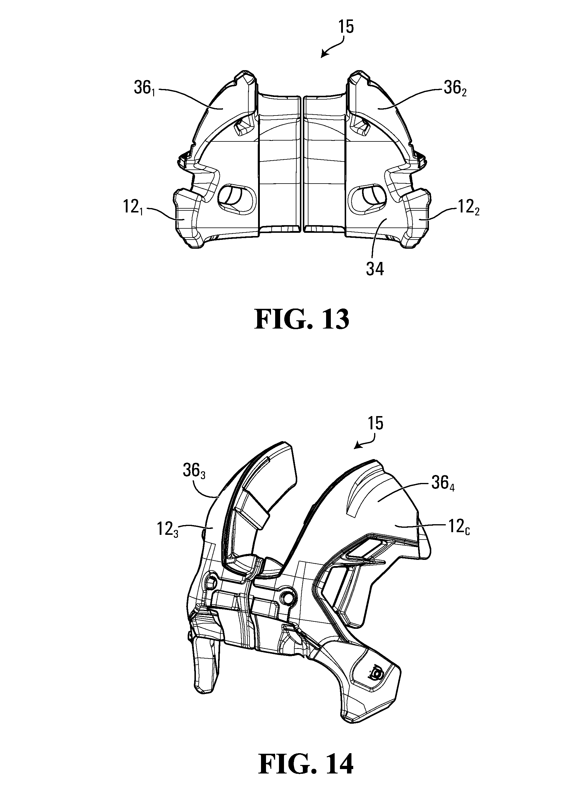
[0020] FIGS. 12 to 16 show respective ones of the pads;
[0021] FIG. 17 shows a front view of an example of a given one of the pads;
[0022] FIG. 18 shows a cross-sectional view the given one of the pads;
[0023] FIG. 18A shows an example of part of a zone of expanded microspheres of the given one of the pads;
[0024] FIG. 19 shows a schematic side view of an example of parts of molding equipment to mold the given one of the pads;
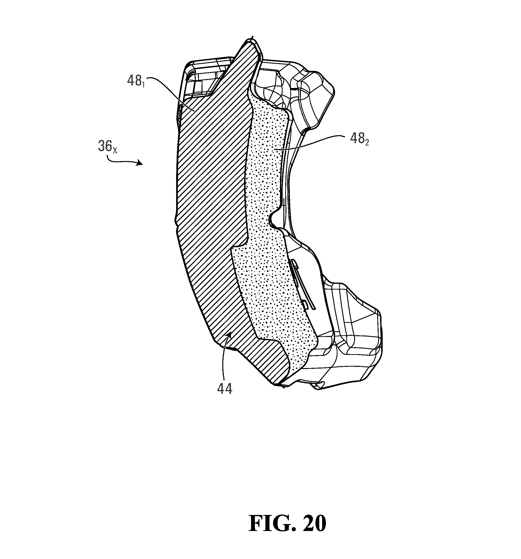
[0025] FIG. 20 shows a cross-sectional view of an example of another embodiment of the given one of the pads;
[0026] FIG. 21A shows a cross-sectional view of an example of another embodiment of the given one of the pads;
[0027] FIG. 21B shows parts of the given one of the pads;
[0028] FIG. 22 shows a cross-sectional view of an example of another embodiment of the given one of the pads;
[0029] FIG. 23 shows a front view of the given one of the pads shown in FIG. 22;
[0030] FIG. 24 shows parts of the given one of the pads shown in FIG. 22;
[0031] FIG. 25 shows a front view of an example of another embodiment of the given one of the pads;
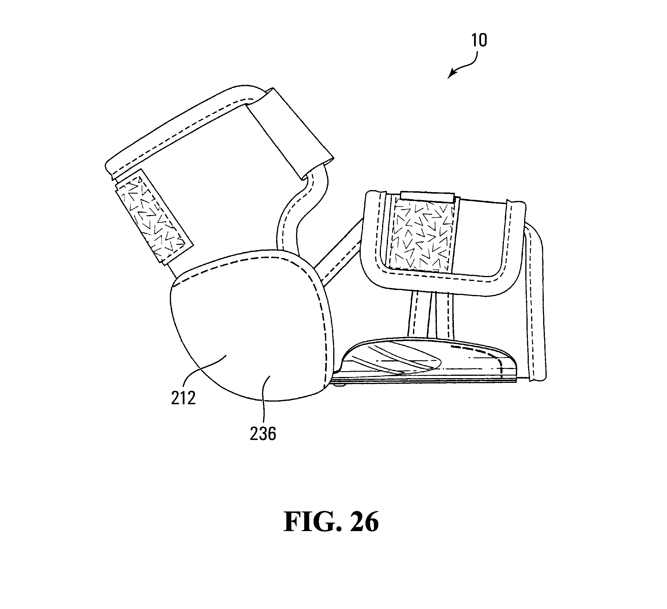
[0032] FIG. 26 shows an embodiment in which the device is an arm guard;
[0033] FIG. 27 shows an embodiment in which the device is shoulder pads;
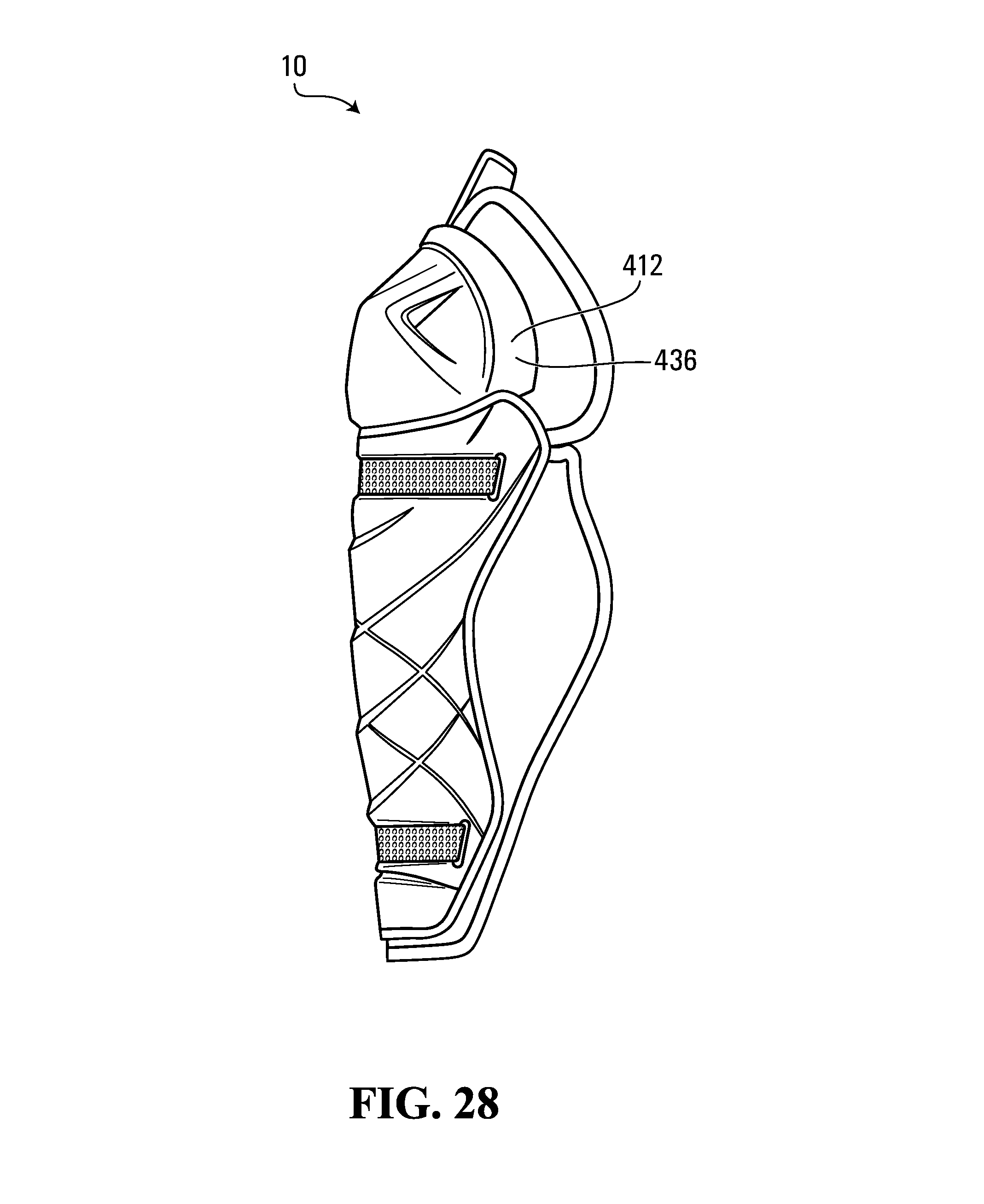
[0034] FIG. 28 shows an embodiment in which the device is a leg guard;
[0035] FIG. 29 shows an embodiment in which the device is a chest protector;
[0036] FIG. 30 shows an embodiment in which the device is a glove;
[0037] FIGS. 31A and 31B show an embodiment in which the device is a hockey stick;
[0038] FIG. 32 shows an embodiment in which the device is a lacrosse stick;
[0039] FIG. 33 shows an embodiment in which the device is a ball bat; and
[0040] FIG. 34 shows an embodiment in which the device is an article of footwear, in this example a skate.
[0041] It is to be expressly understood that the description and drawings are only for the purpose of illustrating certain embodiments and are an aid for understanding. They are not intended to be and are not limiting.
DETAILED DESCRIPTION OF EMBODIMENTS
[0042] FIG. 1 shows an example of an embodiment of a device 10 comprising a plurality of cushioning components 12.sub.1-12.sub.C for absorbing energy when the device 10 is impacted or otherwise contacted. In this embodiment, the device 10 is an article of athletic gear for a user engaging in a sport or other athletic activity. More particularly, in this embodiment, the article of athletic gear 10 is an article of protective athletic gear wearable by the user to protect him/her. Specifically, in this example, the article of protective athletic gear 10 is a helmet for protecting a head of the user against impacts. In this case, the helmet 10 is a hockey helmet for protecting the head of the user, who is a hockey player, against impacts (e.g., from a puck or ball, a hockey stick, a board, ice or another playing surface, etc., with another player, etc.).
[0043] Each of the cushioning components 12.sub.1-12.sub.C of the helmet 10 is configured to protect the player's head by absorbing energy when the helmet 10 is impacted, and may also be provided for comfort of the helmet 10 on the player's head. As further discussed later, in this embodiment, each of the cushioning components 12.sub.1-12.sub.C of the helmet 10 may provide enhanced protection and/or comfort for the player's head while being relatively lightweight, notably by including different materials (e.g., which may differ in density, stiffness, resilience, etc.).
[0044] In this embodiment, the helmet 10 comprises an outer shell 11 and an inner liner 15 that includes the cushioning components 12.sub.1-12.sub.C. The helmet 10 also comprises a chinstrap 16 for securing the helmet 10 to the player's head. The helmet 10 may also comprise a faceguard (not shown) to protect at least part of the player's face (e.g., a grid (sometimes referred to as a "cage") or a visor (sometimes referred to as a "shield")).
[0045] The helmet 10 defines a cavity 13 for receiving the player's head. In response to an impact, the helmet 10 absorbs energy from the impact to protect the player's head. The helmet 10 protects various regions of the player's head. As shown in FIGS. 9A and 9B, the player's head comprises a front region FR, a top region TR, left and right side regions LS, RS, a back region BR, and an occipital region OR. The front region FR includes a forehead and a front top part of the player's head and generally corresponds to a frontal bone region of the player's head. The left and right side regions LS, RS are approximately located above the player's ears. The back region BR is opposite the front region FR and includes a rear upper part of the player's head. The occipital region OR substantially corresponds to a region around and under the head's occipital protuberance.
[0046] The helmet 10 comprises an external surface 18 and an internal surface 20 that contacts the player's head when the helmet 10 is worn. The helmet 10 has a front-back axis FBA, a left-right axis LRA, and a vertical axis VA which are respectively generally parallel to a dorsoventral axis, a dextrosinistral axis, and a cephalocaudal axis of the player when the helmet 10 is worn and which respectively define a front-back direction, a lateral direction, and a vertical direction of the helmet 10. Since they are generally oriented longitudinally and transversally of the helmet 10, the front-back axis FBA and the left-right axis LRA can also be referred to as a longitudinal axis and a transversal axis, respectively, while the front-back direction and the lateral direction can also be referred to a longitudinal direction and a transversal direction, respectively.
[0047] The outer shell 11 provides strength and rigidity to the helmet 10. To that end, the outer shell 11 comprises rigid material 27. For example, in various embodiments, the rigid material 27 of the outer shell 11 may be a thermoplastic material such as polyethylene (PE), polyamide (nylon), or polycarbonate, a thermosetting resin, or any other suitable material. The outer shell 11 includes an inner surface 17 facing the inner liner 15 and an outer surface 19 opposite the inner surface 17. The outer surface 19 of the outer shell 11 constitutes at least part of the external surface 18 of the helmet 10.
[0048] In this embodiment, the outer shell 11 comprises a plurality of shell members 22, 24 that are connected to one another. More particularly, in this embodiment, the shell member 22 is a front shell member and the shell member 24 is a rear shell member. The front shell member 22 comprises a front portion 23 for facing at least part of the front region FR of the player's head, a top portion 21 for facing at least part of the top region TR of the player's head, and left and right lateral side portions 25L, 25R extending rearwardly from the front portion 23 and downwardly from the top portion 21 for facing at least part of the left and right side regions LS, RS of the player's head, respectively. The rear shell member 24 comprises a back portion 31 for facing at least part of the back region BR of the player's head, a top portion 29 for facing at least part of the top region TR of the player's head, an occipital portion 33 for facing at least part of the occipital region OR of the player's head, and left and right lateral side portions 35L, 35R extending forwardly from the back portion 31 and downwardly from the top portion 29 for facing at least part of the left and right side regions LS, RS of the player's head, respectively.
[0049] In this embodiment, the helmet 10 is adjustable to adjust how it fits on the player's head. To that end, the helmet 10 comprises an adjustment mechanism 40 for adjusting a fit of the helmet 10 on the player's head. The adjustment mechanism 40 may allow the fit of the helmet 10 to be adjusted by adjusting one or more internal dimensions of the cavity 13 of the helmet 10, such as a front-back internal dimension FBD of the cavity 13 in the front-back direction of the helmet 10 and/or a left-right internal dimension LRD of the cavity 13 in the left-right direction of the helmet 10, as shown in FIG. 9C.
[0050] More particularly, in this embodiment, the adjustment mechanism 40 is configured such that the outer shell 11 and the inner liner 15 are adjustable to adjust the fit of the helmet 10 on the player's head. To that end, in this embodiment, the shell members 22, 24 are movable relative to one another to adjust the fit of the helmet 10 on the player's head. In this example, relative movement of the shell members 22, 24 for adjustment purposes is in the front-back direction of the helmet 10 such that the front-back internal dimension FBD of the cavity 13 of the helmet 10 is adjusted. This is shown in FIGS. 5 to 8 in which the rear shell member 24 is moved relative to the front shell member 22 from a first position, which is shown in FIG. 5 and which corresponds to a minimum size of the helmet 10, to a second position, which is shown in FIG. 6 and which corresponds to an intermediate size of the helmet 10, and to a third position, which is shown in FIGS. 7 and 8 and which corresponds to a maximum size of the helmet 10.
[0051] In this example of implementation, the adjustment mechanism 40 comprises an actuator 41 that can be moved (e.g., in this case pivoted) by the player between a locked position, in which the actuator 41 engages a locking part 45 (as best shown in FIGS. 8 and 10) of the front shell member 22 and thereby locks the shell members 22, 24 relative to one another, and an unlocked position, in which the actuator 41 is disengaged from the locking part 45 of the front shell member 22 and thereby permits the shell members 22, 24 to move relative to one another so as to adjust the size of the helmet 10. The adjustment mechanism 40 may be implemented in any other suitably way in other embodiments.
[0052] The inner liner 15 is disposed within the outer shell 11, i.e., between the outer shell 11 and the player's head when the helmet 10 is worn. More particularly, the inner liner 15 comprises a shock-absorbing structure 32 that includes an outer surface 38 facing towards the outer shell 11 and an inner surface 34 facing towards the player's head. For example, in some embodiments, the shock-absorbing structure 32 of the inner liner 15 may comprise a shock-absorbing material. For instance, in some cases, the shock-absorbing material may include a polymeric cellular material, such as a polymeric foam (e.g., expanded polypropylene (EPP) foam, expanded polyethylene (EPE) foam, or any other suitable polymeric foam material), or expanded microspheres (e.g., Expancel.TM. microspheres commercialized by Akzo Nobel). Any other material with suitable impact energy absorption may be used in other embodiments. Additionally or alternatively, in some embodiments, the shock-absorbing structure 32 of the inner liner 15 may comprise an array of shock absorbers that are configured to deform when the helmet 10 is impacted. For instance, in some cases, the array of shock absorbers may include an array of compressible cells that can compress when the helmet 10 is impacted. Examples of this are described in U.S. Pat. No. 7,677,538 and U.S. Patent Application Publication 2010/0258988, which are incorporated by reference herein.
[0053] The inner liner 15 may be mounted to the outer shell 11 in any suitable way. For example, in some embodiments, the inner liner 15 may be mounted to the outer shell 11 by one or more fasteners such as mechanical fasteners (e.g., tacks, staples, rivets, screws, stitches, etc.), an adhesive, or any other suitable fastener.
[0054] In this embodiment, the inner liner 15 comprises a plurality of pads 36.sub.1-36.sub.C, 37.sub.1-37.sub.B. In this example, respective ones of the pads 36.sub.1-36.sub.C, 37.sub.1-37.sub.B are movable relative to one another and with the shell members 22, 24 to allow adjustment of the fit of the helmet 10 using the adjustment mechanism 40.
[0055] The pads 36.sub.1-36.sub.C are responsible for absorbing at least a bulk of the energy transmitted to the inner liner 15 when the helmet 10 is impacted and can therefore be referred to as "absorption" pads. In this embodiment, the pad 36.sub.1 is for facing at least part of the front region FR and left side region LS of the player's head, the pad 36.sub.2 is for facing at least part of the front region FR and right side region RS of the player's head, the pad 36.sub.3 is for facing at least part of the back region BR and left side region LS of the player's head, the pad 36.sub.4 is for facing at least part of the back region BR and right side region RS of the player's head, and the pad 36.sub.5 is for facing at least part of the top region TR and back region BR of the player's head. The front shell member 22 overlays the pads 36.sub.1, 36.sub.2, while the rear shell member 24 overlays the pads 36.sub.3, 36.sub.4.
[0056] The pads 37.sub.1-37.sub.B are responsible to provide comfort to the player's head and can therefore be referred to as "comfort" pads. The comfort pads 37.sub.1-37.sub.B may comprise any suitable soft material providing comfort to the player. For example, in some embodiments, the comfort pads 37.sub.1-37.sub.B may comprise polymeric foam such as polyvinyl chloride (PVC) foam, polyurethane foam (e.g., PORON XRD foam commercialized by Rogers Corporation), vinyl nitrile foam or any other suitable polymeric foam material. In some embodiments, given ones of the comfort pads 37.sub.1-37.sub.B may be secured (e.g., adhered, fastened, etc.) to respective ones of the absorption pads 36.sub.1-36.sub.C. In other embodiments, given ones of the comfort pads 37.sub.1-37.sub.B may be mounted such that they are movable relative to the absorption pads 36.sub.1-36.sub.C. For example, in some embodiments, one or more of the comfort pads 37.sub.1-37.sub.B may be part of a floating liner as described in U.S. Patent Application Publication 2013/0025032. The comfort pads 37.sub.1-37.sub.B may assist in absorption of energy from impacts, in particular, low-energy impacts.
[0057] The inner liner 15 comprises the cushioning components 12.sub.1-12.sub.C of the helmet 10. More particularly, in this embodiment, respective ones of the pads 36.sub.1-36.sub.C comprise respective ones of the cushioning components 12.sub.1-12.sub.C of the helmet 10. Specifically, in this example, each cushioning component 12.sub.x of the helmet 10 constitutes a pad 36.sub.x.
[0058] The pad 36.sub.x comprises a periphery 39 that includes an outer side 42 facing towards the outer shell 11 and an inner side 43 opposite to the outer side 42 for facing towards the player's head. In this embodiment, the periphery 39 of the pad 36.sub.x has a three-dimensional shape to accommodate the outer shell 11 and the player's head. More particularly, in this embodiment, each of the outer side 42 and the inner side 43 of the pad 36.sub.x is uneven (i.e., nonplanar in that it comprises one or more angular parts and/or one or more curved parts) to accommodate the outer shell 11 and the player's head. Specifically, in this example, the outer side 42 of the pad 36.sub.x is convex to accommodate the outer shell 11 and the inner side 43 of the pad 36.sub.x is concave to accommodate the player's head.
[0059] In this embodiment, with additional reference to FIGS. 17 and 18, the pad 36.sub.x comprises a core 44 and a covering 46 disposed on the core 44.
[0060] The core 44 of the pad 36.sub.x comprises a periphery 67 that includes an outer side 47 facing towards the outer shell 11 and an inner side 49 opposite to the outer side 47 for facing towards the player's head. The periphery 67 of the core 44 defines the three-dimensional shape of the periphery 39 of the pad 36.sub.x. More particularly, in this embodiment, each of the outer side 47 and the inner side 49 of the core 44 is uneven (i.e., nonplanar in that it comprises one or more angular parts and/or one or more curved parts) to accommodate the outer shell 11 and the player's head. Specifically, in this example, the outer side 47 of the core 44 is convex to accommodate the outer shell 11 and the inner side 49 of the core 44 is concave to accommodate the player's head.
[0061] The core 44 of the pad 36.sub.x comprises a plurality of zones of different materials 48.sub.1-48.sub.Z. Specifically, the zones of different materials 48.sub.1-48.sub.Z of the core 44 are zones differing in at least one material property (e.g., density, modulus of elasticity, resilience, etc.). In some cases, respective ones of the zones of different materials 48.sub.1-48.sub.Z may differ in two or more material properties. The zones of different materials 48.sub.1-48.sub.Z are thus parts of the core 44 that are materially different from one another.
[0062] In this example, the zones of different materials 48.sub.1-48.sub.Z of the core 44 of the pad 36.sub.x include two zones of different materials, namely an outer zone 48.sub.1 of the core 44 and an inner zone 48.sub.2 of the core 44 that is configured to be located closer to the player's head than the outer zone 48.sub.1. A given one of the zones of different materials 48.sub.1-48.sub.Z of the core 44 can be designated as "outer" or "inner" in that it is located outwardly or inwardly relative to another one of the zones of different materials 48.sub.1-48.sub.Z of the core 44. In this case, the outer zone 48.sub.1 of the core 44 constitutes at least part of the outer side 47 of the core 44 while the inner zone 48.sub.2 of the core 44 constitutes at least part of the inner side 49 of the core 44. The zones of different materials 48.sub.1-48.sub.Z of the core 44 of the pad 36.sub.x may comprise three, four, five or more zones of different materials in other examples.
[0063] In this embodiment, respective ones of the zones of different materials 48.sub.1-48.sub.Z of the core 44 of the pad 36.sub.x differ in density.
[0064] More particularly, in this embodiment, a density of the inner zone 48.sub.2 of the core 44 is less than a density of the outer zone 48.sub.1 of the core 44. This may help to provide shock absorption and comfort for the player's head. For instance, in some embodiments, the density of the inner zone 48.sub.2 of the core 44 may be no more than 80%, in some cases no more than 50%, in some cases no more than 20%, and in some cases an even lesser fraction of the density of the outer zone 48.sub.1 of the core 44.
[0065] Each of the density of the outer zone 48.sub.1 of the core 44 and the density of the inner zone 48.sub.2 of the core 44 may have any suitable value. For instance, in some embodiments, the density of the outer zone 48.sub.1 of the core 44 may be no more than 15 lb/ft.sup.3 (0.240 g/cm.sup.3), in some cases no more than 4 lb/ft.sup.3 (0.064 g/cm.sup.3), and in some cases no more than 2 lb/ft.sup.3 (0.032 g/cm.sup.3), and/or the density of the inner zone 48.sub.2 of the core 44 may be no more than 15 lb/ft.sup.3 (0.240 g/cm.sup.3), in some cases no more than 8 lb/ft.sup.3 (0.128 g/cm.sup.3), and in some cases no more than 2 lb/ft.sup.3 (0.032 g/cm.sup.3).
[0066] Respective ones of the zones of different materials 48.sub.1-48.sub.Z of the core 44 may differ in one or more other properties in addition to or instead of density.
[0067] For example, in some embodiments, a modulus of elasticity (i.e., Young's modulus) of the inner zone 48.sub.2 of the core 44 may be less than a modulus of elasticity of the outer zone 48.sub.1 of the core 44. For instance, in some embodiments, the modulus of elasticity of the inner zone 48.sub.2 of the core 44 may be no more than 90%, in some cases no more than 80%, in some cases no more than 70%, and in some cases an even lesser fraction of the modulus of elasticity of the outer zone 48.sub.1 of the core 44. In some cases, the modulus of elasticity may be evaluated according to ASTM D-638 or ASTM D-412. Alternatively, in other embodiments, the modulus of elasticity of the inner zone 48.sub.2 of the core 44 may be greater than the modulus of elasticity of the outer zone 48.sub.1 of the core 44.
[0068] As another example, in some embodiments, a resilience of the inner zone 48.sub.2 of the core 44 may be less than a resilience of the outer zone 48.sub.1 of the core 44. For instance, in some embodiments, the resilience of the inner zone 48.sub.2 of the core 44 may be no more than 80%, in some cases no more than 60%, in some cases no more than 40%, and in some cases an even less fraction of the resilience of the outer zone 48.sub.1 of the core 44 according to ASTM D2632-01 which measures resilience by vertical rebound. Alternatively, in other embodiments, the resilience of the inner zone 48.sub.2 of the core 44 may be greater than the resilience of the outer zone 48.sub.1 of the core 44. Each of the resilience of the inner zone 48.sub.2 of the core 44 and the resilience of the outer zone 48.sub.1 of the core 44 may have any suitable value.
[0069] As another example, in some embodiments, an elongation at break of the inner zone 48.sub.2 of the core 44 may be greater than an elongation at break of the outer zone 48.sub.1 of the core 44. For instance, in some embodiments, the elongation at break of the inner zone 48.sub.2 of the core 44 may be at least 110%, in some cases at least 130%, and in some cases at least 150% of the elongation at break of the outer zone 48.sub.1 of the core 44 according to ASTM D-638 or ASTM D-412, and in some cases even more.
[0070] Each of the elongation at break of the inner zone 48.sub.2 of the core 44 and the elongation at break of the outer zone 48.sub.1 of the core 44 may have any suitable value. For instance, in some embodiments, the elongation at break of the inner zone 48.sub.2 of the core 44 may be at least 20%, in some cases at least 40%, in some cases at least 60%, and in some cases even more, and/or the elongation at break of the outer zone 48.sub.1 of the core 44 may be at least 20%, in some cases at least 40%, in some cases at least 60%, and in some cases even more.
[0071] As another example, in some embodiments, a hardness (e.g., Shore OO hardness) of the inner zone 48.sub.2 of the core 44 may be less than a hardness of the outer zone 48.sub.1 of the core 44. For instance, in some embodiments, on a Shore OO hardness scale, a ratio of the hardness of the inner zone 48.sub.2 of the core 44 over the hardness of the outer zone 48.sub.1 may be no more than 0.9, in some cases no more than 0.5, in some cases no more than 0.3, and in some cases an even lesser ratio. In some cases, the hardness may be evaluated according to ASTM D2240. Alternatively, in other embodiments, the hardness of the inner zone 48.sub.2 of the core 44 may be greater than the hardness of the outer zone 48.sub.1 of the core 44.
[0072] As another example, in some embodiments, an indentation force deflection (IFD) of the inner zone 48.sub.2 of the core 44 may be less than an IFD of the outer zone 48.sub.1 of the core 44. For instance, in some embodiments, the IFD of the inner zone 48.sub.2 of the core 44 may be no more than 95%, in some cases no more than 80%, in some cases no more than 60%, and in some cases an even less fraction of the IFD of the outer zone 48.sub.1 of the core 44 according to ASTM D3574 which measures the force required to compress a foam material 25% of its thickness. Alternatively, in other embodiments, the IFD of the inner zone 48.sub.2 of the core 44 may be greater than the IFD of the outer zone 48.sub.1 of the core 44.
[0073] Each of the IFD of the inner zone 48.sub.2 of the core 44 and the IFD of the outer zone 48.sub.1 of the core 44 may have any suitable value. For instance, in some embodiments, the IFD of the inner zone 48.sub.2 of the core 44 may be no more than 15 pound-force per square inch (psi), in some cases no more than 10 psi, and in some cases no more than 6 psi according to ASTM D3574, and/or the IFD of the outer zone 48.sub.1 of the core 44 may be no more than 20 psi, in some cases no more than 16 psi, and in some cases no more than 12 psi according to ASTM D3574.
[0074] The zones of different materials 48.sub.1-48.sub.Z of the core 44 of the pad 36.sub.x may include any suitable materials.
[0075] In this embodiment, with additional reference to FIG. 18, each of the outer zone 48.sub.1 and the inner zone 48.sub.2 of the core 44 is a zone of expanded microspheres 60.sub.1-60.sub.M. That is, each of the outer zone 48.sub.1 and the inner zone 48.sub.2 of the core 44 is at least mainly (i.e., mainly or entirely) made of expanded microspheres 60.sub.1-60.sub.M. Each expanded microsphere 60.sub.x comprises a polymeric shell 62 expanded by a fluid encapsulated in an interior of the polymeric shell. In this example, the polymeric shell 62 of the expanded microsphere 60.sub.x is a thermoplastic shell. The fluid encapsulated in the polymeric shell 62 is a liquid or gas (in this case a gas) able to expand the expanded microsphere 60.sub.x when heated during manufacturing of the pad 36.sub.x. In some embodiments, the expandable microspheres 60.sub.1-60.sub.M may be Expancel.TM. microspheres commercialized by Akzo Nobel. In other embodiments, the expandable microspheres 60.sub.1-60.sub.M may be Dualite microspheres commercialized by Henkel; Advancell microspheres commercialized by Sekisui; Matsumoto Microsphere microspheres commercialized by Matsumoto Yushi Seiyaku Co; or KUREHA Microsphere microspheres commercialized by Kureha. Various other types of expanded microspheres may be used in other embodiments.
[0076] The expanded microspheres 60.sub.1-60.sub.M may be provided in any suitable form during manufacturing of the pad 36.sub.x. For example, in some embodiments, the expanded microspheres 60.sub.1-60.sub.M may include dry unexpanded, dry expanded, wet unexpanded, wet expanded, and/or partially-expanded dry and/or wet microspheres.
[0077] As discussed above, in this embodiment, the inner zone 48.sub.2 of expanded microspheres of the core 44 is less dense than the outer zone 48.sub.1 of expanded microspheres of the core 44.
[0078] In this embodiment, each of the outer zone 48.sub.1 of expanded microspheres of the core 44 and the inner zone 48.sub.2 of expanded microspheres of the core 44 constitutes at least a substantial part (i.e., a substantial part or an entirety) of the core 44. More particularly, in this embodiment, each of the outer zone 48.sub.1 of expanded microspheres of the core 44 and the inner zone 48.sub.2 of expanded microspheres of the core 44 constitutes at least one-quarter of the core 44 by weight, in some cases at least one-third of the core 44 by weight, and in some cases at least half of the core 44 by weight. Specifically, in this case, the outer zone 48.sub.1 of expanded microspheres of the core 44 is larger than the inner zone 48.sub.2 of expanded microspheres of the core 44, with the outer zone 48.sub.1 of expanded microspheres of the core 44 constituting about 70% of the core 44 by weight and the inner zone 48.sub.2 of expanded microspheres of the core 44 constituting about 30% of the core 44 by weight.
[0079] Thus, in this embodiment, the expanded microspheres 60.sub.1-60.sub.M of the inner and outer zones 48.sub.1, 48.sub.2 of the core 44 constitute a substantial part (i.e., a substantial part or an entirety) of the core 44 by weight. More particularly, in this embodiment, the expanded microspheres 60.sub.1-60.sub.M of the inner and outer zones 48.sub.1, 48.sub.2 of the core 44 constitute at least one-quarter of the core 44 by weight, in some cases at least one-third of the core 44 by weight, and in some cases at least a majority of the core by weight. Specifically, in this example, the expanded microspheres 60.sub.1-60.sub.M of the inner and outer zones 48.sub.1, 48.sub.2 of the core 44 constitute at least 80%, in this case, substantially the entirety of the core 44.
[0080] The zones of different materials 48.sub.1-48.sub.Z of the core 44 of the pad 36.sub.x may be arranged in any suitable way and have any suitable size and configuration.
[0081] In this embodiment, each of a thickness T.sub.1 of the outer zone 48.sub.1 of the core 44 and a thickness T.sub.2 of the inner zone 48.sub.2 of the core 44 corresponds to a significant part of a thickness T.sub.C of the core 44. More particularly, in this embodiment, each of the thickness T.sub.1 of the outer zone 48.sub.1 of the core 44 and the thickness T.sub.2 of the inner zone 48.sub.2 of the core 44 corresponds to at least one-quarter, in some cases at least one-third, and in some cases at least a majority of the thickness T.sub.C of the core 44. Specifically, in this example, each of the thickness T.sub.1 of the outer zone 48.sub.1 of the core 44 and the thickness T.sub.2 of the inner zone 48.sub.2 of the core 44 corresponds to more than half of the thickness T.sub.C of the core 44.
[0082] Also, in this embodiment, the outer zone 48.sub.1 of the core 44 and the inner zone 48.sub.2 of the core 44 may be interlocked. For instance, in this embodiment, a given one of the outer and inner zones 48.sub.1, 48.sub.2 of the core 44 and an adjacent one of the outer and inner zones 48.sub.1, 48.sub.2 of the core 44 are interlocked by an interlocking part 61 of the given one of the outer and inner zones 48.sub.1, 48.sub.2 of the core 44 extending into an interlocking void 63 of the adjacent one of the outer and inner zones 48.sub.1, 48.sub.2 of the core 44. This may be done to facilitate manufacturing (e.g., molding) of the outer and inner zones 48.sub.1, 48.sub.2 of the core 44) and/or to help secure them.
[0083] In this embodiment, the inner zone 48.sub.2 of the core 44 comprises projections 64.sub.1-64.sub.6 projecting from an adjacent part 65 of the inner side 49 of the core 44 and spaced from one another. The projections 64.sub.1-64.sub.6 may provide areas of increased cushioning and may facilitate air circulations thereabout.
[0084] The covering 46 of the pad 36.sub.x covers at least a substantial part (i.e., a substantial part or an entirety) of the core 44 of the of the pad 36.sub.x. This may help to retain integrity of the core 44. For example, in this embodiment, this may help to retain the zones of different materials 48.sub.1-48.sub.Z of the core 44 together. Also, in this embodiment in which the core 44 includes expanded microspheres, the covering 46 may help to protect the outer and inner zones 48.sub.1, 48.sub.2 of expanded microspheres against chipping, crumbling or cracking in use, as their expanded microspheres may otherwise be friable.
[0085] In this embodiment, the covering 46 covers at least part of the inner side 49 of the core 44 and at least part of the outer side 47 of the core 44. More particularly, in this embodiment, the covering 46 covers at least a majority of the periphery 67 of the core 44. In this example, the covering 46 covers at least a majority, in this case all, of the inner side 49 of the core 44 and at least a majority, in this case all, of the outer side 47 of the core 44. Specifically, in this example, the covering 46 envelopes the core 44 (i.e., completely encloses the core 44). This may help to maximize an effect of the covering 46 in retaining integrity of the core 44.
[0086] More particularly, in this embodiment, the covering 46 is molded to conform to the core 44. That is, the covering 46 is shaped by molding equipment including one or more molds in order to conform to the core 44 during a molding process for making the pad 36.sub.x, as further discussed later. This allows the covering 46 to closely follow and match the periphery 67 of the core 44. Also, the covering 46 is affixed to the core 44. In this case, the covering 46 is bonded to the core 44 during the molding process.
[0087] In this example of implementation, the covering 46 comprises a layer of polymeric material 70 molded to conform to the core 44. In this embodiment, the layer of polymeric material 70 is a layer of polyurethane (e.g., thermoplastic polyurethane). The layer of polymeric material 70 may include any other suitable polymeric material in other embodiments (e.g. polyester, nylon fabric, etc.).
[0088] In this embodiment, the covering 46 comprises an outer covering member 51 that covers the outer side 47 of the core 44 and an inner covering member 53 that covers the inner side 49 of the core 44. More particularly, in this embodiment, the outer and inner covering members 51, 53 comprise respective parts of the layer of polymeric material 70 and meet at a junction 55. The outer and inner covering members 51, 53 may be formed separately during manufacturing of the pad 36.sub.x, as discussed later.
[0089] The covering 46 is significantly thinner than the core 44. For example, in some embodiments, a thickness T.sub.E of the covering 46 corresponds to no more than 10%, in some cases no more than 5%, and in some cases no more than 2% of the thickness T.sub.C of the core 44. For instance, in some embodiments, the thickness T.sub.E of the covering 46 may be no more than 2 mm, in some cases no more than 0.5 mm, in some cases no more than 0.2 mm, and in some cases even less.
[0090] In this embodiment, the covering 46 may be used to enhance an appearance of the pad 36.sub.x. For example, in this embodiment, the covering 46 displays a decoration 72 that includes an arrangement of a plurality of different colors. This may be useful as the 36.sub.1-36.sub.C occupy a significant area within the helmet 10.
[0091] More particularly, in this embodiment, the decoration 72 is defined by the layer of polymeric material 70 and includes four different colors. In this example, the decoration 72 includes areas of contrasting colors and lines in one color which are spaced apart by gaps having another color and which cross other lines.
[0092] The decoration 72 of the covering 46 may take on any other suitable configuration in other embodiments. For instance, in some embodiments, the decoration 72 may include a graphical representation of: one or more alphanumeric characters that may form text (e.g., a word, a message, etc.); one or more symbols (e.g., a logo, a sign, an emblem, etc.); one or more shapes or patterns; and/or one or more real or imaginary objects (e.g., a person, an animal, a vehicle, an imaginary or fictional character, or any other real or imaginary thing). For example, in some embodiments, the arrangement of colors of the decoration 72 may represent colors and/or a logo of a sports team for which the player plays.
[0093] The decoration 72 may be provided in any suitable way. For example, in this embodiment, the decoration 72 may be provided by silk-screening. In other embodiments, the decoration 72 may be provided by sublimation, roller printing, pad printing, or any other suitable technique.
[0094] The covering 46 may be implemented in various other ways in other embodiments. For example, in some embodiments, the covering 46 may comprise a fabric layer, such as a non-woven fabric layer or a woven fabric layer (e.g., of spandex, nylon, polyester, polypropylene, or any other suitable fabric material). As another example, in some embodiments, the covering 46 may comprise a plurality of layers of different materials. For instance, in some embodiments, the inner covering member 53 that covers the inner side 49 of the core 44 may include the layer of polymeric material 70 (e.g., polyurethane), while the outer covering member 51 that covers the outer side 47 of the core 44 may include a fabric layer. As yet another example, in some embodiments, the covering 46 may comprise a plurality of layers that are stacked.
[0095] In this embodiment, the pad 36.sub.x comprises a plurality of ventilation holes 80.sub.1, 80.sub.2. In this example, the ventilation holes 80.sub.1, 80.sub.2 are aligned with ventilation holes 82.sub.1, 80.sub.2 of the outer shell 11. Each ventilation hole 80.sub.x of the pad 36.sub.x extends through the core 44 and is defined by an interior surface 90 of the core 44, and the covering 46 covers at least part, in this case all, of the internal surface 90 of the core 44.
[0096] The pad 36.sub.x may be manufactured in various ways. In this embodiment, the pad 36.sub.x is made by a molding process in which its core 44 is molded into shape and its covering 46 is molded to conform to the core 44. The molding process uses molding equipment including one or more molds to shape the core 44 and the covering 46.
[0097] The zones of different materials 48.sub.1-48.sub.Z are provided. In this embodiment, each of the outer and inner zones 48.sub.1, 48.sub.2 of the core 44 is provided separately. More particularly, in this embodiment, each of the outer and inner zones 48.sub.1, 48.sub.2 of the core 44 is molded into shape by the molding equipment. For instance, as the outer and inner zones 48.sub.1, 48.sub.2 of the core 44 have different shapes, a mold having a cavity corresponding to a three-dimensional shape of the outer zone 48.sub.1 of the core 44 may be used to form the outer 48.sub.1 of the core 44, whereas another mold having a cavity corresponding to a three-dimensional shape of the inner zone 48.sub.2 of the core 44 may be used to form the inner zone 48.sub.1 of the core 44.
[0098] In this embodiment, as it is a zone of expanded microspheres 60.sub.1-60.sub.M, each of the outer and inner zones 48.sub.1, 48.sub.2 of the core 44 is formed by placing an amount of microspheres in the cavity of the mold in which it is to be formed. In some examples, the microspheres placed into the mold may include unexpanded microspheres (e.g., dry unexpanded microspheres in a loose powder, wet unexpanded microspheres in a paste-like form). Alternatively or additionally, in some examples, the microspheres placed into the mold may include pre-expanded microspheres that have been previously heated to pre-expand them (e.g., either partially or fully expand them). Also, in some examples, any other minor constituent of the outer and inner zones 48.sub.1, 48.sub.2 of the core 44 (e.g., a color pigment substance) may be placed into the mold with the microspheres.
[0099] Each of the outer and inner zones 48.sub.1, 48.sub.2 of the core 44 is separately molded in the mold in which is to be formed by applying heat. As part of the molding process, microspheres provided in the mold expand. The molding process may then include a cold molding phase in which the temperature is lowered. Temperature and pressure of the molding process cause bonding of adjacent ones of the expanded microspheres.
[0100] The covering 46 is molded to conform to the core 44. In this embodiment, each of the outer and inner covering members 51, 53 of the covering 46 is provided separately. More particularly, in this embodiment, each of the outer and inner covering members 51, 53 is molded into shape by the molding equipment to respectively conform to the outer and inner sides 47, 49 of the core 44. For instance, in some embodiments, a mold comprising a cavity that includes a surface corresponding to a three-dimensional shape of the outer covering member 51 and that of the outer side 47 of the core 44 may be used to form the outer covering member 51, and another mold comprising a cavity that includes a surface corresponding to a three-dimensional shape of the inner covering member 53 and that of the inner side 49 of the core 44 may be used to form the inner covering member 53.
[0101] In some embodiments, a precursor of each of the outer and inner covering members 51, 53 is prepared for placement into the mold in which it is to be formed in order to conform to the core 44. More particularly, in this embodiment, the precursor of each of the outer and inner covering members 51, 53 includes a sheet (e.g., which may have been previously cut from a larger sheet). In this example, the sheet comprises part of the layer of polymeric material 70. In some cases, the sheet may include the decoration 72.
[0102] Molding of the sheet of each of the outer and inner covering members 51, 53 into the mold in which it is to be formed in order to conform to the core 44 may be achieved in any suitable way. In this embodiment, at least part of the covering 46 is vacuum-formed to conform to the core 44. For example, in this embodiment, the sheet to form the inner covering member 53 is vacuum-formed in the mold for shaping the inner covering member 53. The inner zone 48.sub.2 of the core 44 is then placed on the inner covering member 53, which has been vacuum-formed. The outer zone 48.sub.1 of the core 44 is then placed on the inner zone 48.sub.2 of the core 44. The sheet to form the outer covering member 51 is then placed on the outer zone 48.sub.1 of the core 44 in the mold in which it is to be formed to conform to the outer zone 48.sub.1 of the core 44. For instance, in some embodiments, the sheet to form the outer covering member 51 may be vacuum-formed in the mold, which is then closed. Alternatively, in some embodiments, the sheet to form the inner covering member 53 may be shaped to conform to the outer zone 48.sub.1 of the core 44 when the mold is closed and it is pressed against the outer zone 48.sub.1 of the core 44.
[0103] The covering 46 is bonded to the core 44 during the molding process. More particularly, in this embodiment, the outer and inner covering members 51, 53 are respectively bonded to the outer and inner sides 47, 49 of the core 44. In some embodiments, a hot-melt adhesive film or another adhesive may be associated with one or both of the outer and inner covering members 51, 53 to enhance bonding to the core 44. In this example, the outer and inner covering members 51, 53 meet at their junction 55 where they are joined, thereby enveloping the core 44. The molding process may then include a cold molding phase in which the temperature is lowered.
[0104] The pad 36.sub.x, with its core 44 shaped and its covering 62 molded to conform to its core 44, is removed from the molding equipment and may be finished by one or more post-molding operations. For example, in some embodiments, a trimming operation may be performed to remove excess material from the covering 46 that extends beyond the core 44 (e.g., at the junction 55 of the outer and inner covering members 51, 53).
[0105] Various other manufacturing techniques may be used to make the pad 36.sub.x in other embodiments.
[0106] The pad 36.sub.x, including its core 44 and its covering 46, may be implemented in various other ways in other embodiments.
[0107] For example, in some embodiments, as shown in FIG. 20, a state of the inner zone 48.sub.2 of expanded microspheres of the core 44 may be different from a state of the outer zone 48.sub.1 of expanded microspheres of the core 44. That is, the expanded microspheres 60.sub.1-60.sub.M of the inner zone 48.sub.2 of the core 44 may be in a different state from those of the outer zone 48.sub.1 of the core 44.
[0108] More particularly, in this embodiment, the outer zone 48.sub.1 of expanded microspheres of the core 44 is consolidated, i.e., its expanded microspheres 60.sub.1-60.sub.M are consolidated such that the outer zone 48.sub.1 is substantially solid, while the inner zone 48.sub.2 of expanded microspheres of the core 44 is unconsolidated, i.e., its expanded microspheres 60.sub.1-60.sub.M are unconsolidated such that the inner zone 48.sub.2 is softer and more malleable than the outer zone 48.sub.1. For instance, in some embodiments, the unconsolidated expanded microspheres 60.sub.1-60.sub.M of the inner zone 48.sub.2 of the core 44 may be in a paste-like form. The unconsolidated state (e.g., paste-like form) of the expanded microspheres 60.sub.1-60.sub.M of the inner zone 48.sub.2 may be achieved by encapsulating the inner zone 48.sub.2 with the inner covering member 53 while it is vacuum-formed, wherein the vacuum molding process is performed at a temperature lower than the consolidation temperature of the expanded microspheres 60.sub.1-60.sub.M This may help to enhance a cushioning effect of the inner zone 48.sub.2 of the core 44.
[0109] As another example, in some embodiments, as shown in FIG. 21A, one or more of the zones of different materials 48.sub.1-48.sub.Z of the core 44 of the pad 36.sub.x may not be a zone of expanded microspheres (i.e., not be mainly or entirely made of expanded microspheres, but may rather be a zone at least mainly made of material other than expanded microspheres). For instance, in this embodiment, the inner zone 48.sub.2 of the core 44 is a zone of foam 85, i.e., a zone at least mainly (i.e., mainly or entirely) made of foam 85, while the outer zone 48.sub.1 of the core 44 is a zone of expanded microspheres as discussed above. The foam 85 may help to enhance comfort for the player's head. This may also be useful to provide better impact absorption or other protection against linear and rotational impacts.
[0110] In this embodiment, the foam 85 includes polyurethane foam (e.g., PORON XRD foam commercialized by Rogers Corporation, or any other suitable polyurethane foam). The foam 85 may include any other suitable foam in other embodiments (e.g., polyvinyl chloride (PVC) foam, vinyl nitrile foam, etc.).
[0111] More particularly, in this embodiment, as shown in FIG. 21B, before being molded, the foam 85 of the inner zone 48.sub.2 of the core 44 of the pad 36.sub.x includes: a foam layer 86 (e.g., which may include one or more foam plies) that forms a "base" which extends over at least a majority, in this case all, of the inner side 49 of the core 44 to be molded; a foam layer of foam 87 that is smaller than and overlies the foam layer 86 in a specific region of the inner zone 48.sub.2 (e.g., in this case a region located underneath the projection 64.sub.1); and respective portions of a foam layer 89 for forming each of the projections 64.sub.1-64.sub.6 projecting from the adjacent part 65 of the inner side 49 of the core 44 and spaced from one another.
[0112] In this embodiment, the outer zone 48.sub.1 of the core 44 may be formed by placing an amount of microspheres in the cavity of the mold in which it is to be formed by applying heat as described earlier, and the inner zone 48.sub.2 of the core 44 may be formed by placing the foam layers 86, 87, 89 of the foam 85 into the cavity in which it is to be formed (e.g., on the outer zone 48.sub.1 of the core 44) so that after molding the foam layers 86, 87, 89 of the foam 85 amalgamate into the inner zone 48.sub.2 of the core 44.
[0113] As another example, in some embodiments, as shown in FIGS. 22 to 24, the zones of different materials 48.sub.1-48.sub.Z of the core 44 of the pad 36.sub.x may be more than two in number, such as three, four or more zones. For instance, in this embodiment, the outer zone 48.sub.1 of the core 44 is a zone of expanded microspheres and the inner zone 48.sub.2 of the core 44 is a zone of foam as discussed above, while there is another inner zone 48.sub.3 of foam 88 different from the foam 85 of the inner zone 48.sub.2. In this case, the inner zone 48.sub.3 of the core 44 comprises the projections 64.sub.1-64.sub.6 projecting from the adjacent part 65 of the inner side 49 of the core 44 and spaced from one another.
[0114] In this embodiment, the foam 88 includes polyurethane foam (e.g., PORON XRD foam commercialized by Rogers Corporation, or any other suitable polyurethane foam). The foam 85 may include any other suitable foam in other embodiments (e.g., polyvinyl chloride (PVC) foam, vinyl nitrile foam, etc.).
[0115] More particularly, in this embodiment, the density of the foam 85 is different from the density of the foam 88. In this example, the density of the foam 88 is less than the density of the foam 85. For instance, in some embodiments, the density of the foam 88 may be no more than 90%, in some cases no more than 80% and in some cases no more than 70% of the density of the foam 85. Alternatively, in other embodiments, the foam 88 may be denser than the foam 85.
[0116] As another example, in some embodiments, as shown in FIG. 25, the inner zone 48.sub.2 of the core 44 of the pad 36.sub.x may be perforated such that it comprises a plurality of apertures 91.sub.1-91.sub.A. This may be useful to enhance ventilation and provide sweat management to the player.
[0117] As another example, in some embodiments, the covering 46 of the pad 36.sub.x may cover less than the entirety of the core 44 of the pad 36.sub.x. For example, in some embodiments, certain regions of the inner side 49 and/or certain regions of the outer side 47 of the core 44 may not be covered by the covering 46 but may rather be exposed.
[0118] Although in this embodiment the article of protective athletic gear 10 is the helmet 10, in other embodiments, the article of protective athletic gear 10 may be any other article of protective athletic gear comprising one or more cushioning components constructed using principles described herein in respect of the cushioning components 12.sub.1-12.sub.C.
[0119] For example, in some embodiments, as shown in FIG. 26, the article of protective athletic gear 10 may be an arm guard (e.g., an elbow pad) for protecting an arm (e.g., an elbow) of a user, in which the arm guard 10 comprises a cushioning component 212 constructed using principles described herein in respect of cushioning components 12.sub.1-12.sub.C and constituting a pad 236 of the arm guard 10.
[0120] As another example, in some embodiments, as shown in FIG. 27, the article of protective athletic gear 10 may be shoulder pads for protecting an upper torso (e.g., shoulders and a chest) of a user, in which the shoulder pads 10 comprise a cushioning component 312 constructed using principles described herein in respect of the cushioning components 12.sub.1-12.sub.C and constituting a pad 336 of the shoulder pads 10.
[0121] As another example, in some embodiments, as shown in FIG. 28, the article of protective athletic gear 10 may be a leg guard for protecting a leg of a user, in which the leg guard 10 comprises a cushioning component 412 constructed using principles described herein in respect of the cushioning components 12.sub.1-12.sub.C and constituting a pad 436 of the leg guard 10.
[0122] As another example, in some embodiments, as shown in FIG. 29, the article of protective athletic gear 10 may be a chest protector for a goalie or baseball catcher for protecting his/her chest, in which the chest protector 10 comprises a cushioning component 712 constructed using principles described herein in respect of the cushioning components 12.sub.1-12.sub.C and constituting any portion of the chest protector 10 (e.g., a chest portion, an abdominal portion, an arm portion if present, etc.).
[0123] As another example, in some embodiments, as shown in FIG. 30, the article of protective athletic gear 10 may be a glove for protecting a user's hand, in which the glove 10 comprises a cushioning component 812 constructed using principles described herein in respect of the cushioning components 12.sub.1-12.sub.C. For example, in this case, the glove 10 is a blocker glove for a goalie and the cushioning component 812 constitutes a board portion of the blocker glove 10 to deflect pucks or balls.
[0124] In some embodiments, the article of athletic gear 10 may be used for purposes other than protection.
[0125] For instance, in some embodiments, with additional reference to FIGS. 31 to 33, the article of athletic gear 10 may be a sports implement for handling by a user, in which the sports implement 10 comprises a cushioning component 612 constructed using principles described herein in respect of the cushioning components 12.sub.1-12.sub.C. For example, in some embodiments, a core 644 of the cushioning component 612 may be constructed using principles described herein in respect of the core 44 of each of the cushioning components 12.sub.1-12.sub.C in order to provide shock absorbance, while a covering 646 of the cushioning component 612 may be constructed using principles described herein in respect of the covering 46 of each of the cushioning components 12.sub.1-12.sub.C but comprise rigid material 670 that imparts strength and rigidity (e.g., that forms a wall of the sports implement 10). In some embodiments, the rigid material 670 may comprise fiber-reinforced polymeric material (e.g., carbon-fiber-reinforced polymeric material or glass-fiber-reinforced polymeric material) or any other composite material that is provided (e.g., wrapped as pre-impregnated fiber tape) about the core 644.
[0126] For example, in some embodiments, as shown in FIG. 31, the sports implement 10 may be a hockey stick. The hockey stick 10 comprises a shaft 620, a handle 622 disposed at a proximal end portion of the shaft 620, and a blade 624 disposed adjacent a distal end portion of the shaft 620. In this embodiment, the blade 624 of the hockey stick 10 comprises the cushioning component 612. In other embodiments, the handle 622 of the hockey stick 10 may comprise the cushioning component 612 or another cushioning component similar to the cushioning component 612. In yet other embodiments, the blade 624 of the hockey stick 10 may comprise the cushioning component 612, while the handle 622 of the hockey stick 10 may comprise another cushioning component similar to the cushioning component 612.
[0127] As another example, with additional reference to FIG. 32, the sports implement 10 may be a lacrosse stick. The lacrosse stick 10 comprises a shaft 650, a handle 652 disposed at a proximal end portion of the shaft 650, and a lacrosse head 654 disposed adjacent a distal end portion of the shaft 650. In this example, the handle 652 of the lacrosse stick 10 comprises the cushioning component 612.
[0128] As another example, with additional reference to FIG. 33, the sports implement 10 may be a ball bat, such as a baseball bat or a softball bat. The ball bat 10 comprises a handle 752, a barrel 754, and a tapered transition 755 between the handle 752 and the barrel 754. In this example, the barrel 754 comprises the cushioning component 612.
[0129] As another example, in some embodiments, as shown in FIG. 34, the article of athletic gear 10 may be an article of footwear comprising a cushioning component 512 constructed using principles described herein in respect of the cushioning components 12.sub.1-12.sub.C. In this embodiment, the article of footwear 10 is a skate. For example, in this case, the skate 10 is a hockey skate for a hockey player. The skate 10 comprises a boot 525, a blade holder 547 and a blade 549. In this example, the cushioning component 512 constitutes a portion of the boot 525. More particularly, in this example, the cushioning component 512 constitutes a sole portion of the boot 525). The article of footwear 10 may be any other type of footwear (e.g., shoes) in other embodiments.
[0130] Although in embodiments considered above the article of athletic gear 10 is hockey, lacrosse, or baseball/softball gear, in other embodiments, the article of athletic gear 10 may be any other article of athletic gear usable by a player playing another type of contact sport (e.g., a "full-contact" sport) in which there are significant impact forces on the player due to player-to-player and/or player-to-object contact or any other type of sports, including athletic activities other than contact sports. For example, in other embodiments, the article of athletic gear 10 may be an article of football gear for a football player, an article of soccer gear for a soccer player, etc.
[0131] In other embodiments, a device comprising one or more cushioning components constructed using principles described herein in respect of the cushioning components 12.sub.1-12.sub.C may be anything other than an article of athletic gear and may thus be designed for any suitable purpose. For example, this may include blunt trauma personal protective equipment (PPE), automotive interior components, chair cushioning components, bed cushioning/mattresses, etc.
[0132] Certain additional elements that may be needed for operation of some embodiments have not been described or illustrated as they are assumed to be within the purview of those of ordinary skill in the art. Moreover, certain embodiments may be free of, may lack and/or may function without any element that is not specifically disclosed herein.
[0133] Any feature of any embodiment discussed herein may be combined with any feature of any other embodiment discussed herein in some examples of implementation.
[0134] In case of any discrepancy, inconsistency, or other difference between terms used herein and terms used in any document incorporated by reference herein, meanings of the terms used herein are to prevail and be used.
[0135] Although various embodiments and examples have been presented, this was for purposes of description but this should not be limiting. Various modifications and enhancements will become apparent to those of ordinary skill in the art.
* * * * *
D00000
D00001
D00002
D00003
D00004
D00005
D00006
D00007
D00008
D00009
D00010
D00011
D00012

D00013

D00014

D00015
D00016

D00017

D00018

D00019

D00020

D00021

D00022
D00023

D00024
D00025

D00026

D00027

D00028

D00029

XML
uspto.report is an independent third-party trademark research tool that is not affiliated, endorsed, or sponsored by the United States Patent and Trademark Office (USPTO) or any other governmental organization. The information provided by uspto.report is based on publicly available data at the time of writing and is intended for informational purposes only.
While we strive to provide accurate and up-to-date information, we do not guarantee the accuracy, completeness, reliability, or suitability of the information displayed on this site. The use of this site is at your own risk. Any reliance you place on such information is therefore strictly at your own risk.
All official trademark data, including owner information, should be verified by visiting the official USPTO website at www.uspto.gov. This site is not intended to replace professional legal advice and should not be used as a substitute for consulting with a legal professional who is knowledgeable about trademark law.