Flash Assembly Of Mobile Terminal, Control System Thereof And Control Method Thereof
Jiao; Tao
U.S. patent application number 16/309942 was filed with the patent office on 2019-05-30 for flash assembly of mobile terminal, control system thereof and control method thereof. The applicant listed for this patent is JRD COMMUNICATION (SHENZHEN) LTD. Invention is credited to Tao Jiao.
| Application Number | 20190166243 16/309942 |
| Document ID | / |
| Family ID | 57816210 |
| Filed Date | 2019-05-30 |


| United States Patent Application | 20190166243 |
| Kind Code | A1 |
| Jiao; Tao | May 30, 2019 |
FLASH ASSEMBLY OF MOBILE TERMINAL, CONTROL SYSTEM THEREOF AND CONTROL METHOD THEREOF
Abstract
The present disclosure provides a flash assembly of a mobile terminal, the flash assembly is a display assembly, and the display assembly disposed at a front end of a camera assembly of the mobile terminal and connects to a processor of the mobile terminal via an I2C. The present disclosure also provides a control system, comprising a scene predictor, a controller and a flash assembly. A control method is also provided. Compared with the related art, the protective cover of the camera is replaced by a display assembly, thereby reducing the number of components; and the display assembly can reduce the thermal output.
| Inventors: | Jiao; Tao; (Shenzhen, Guangdong, CN) | ||||||||||
| Applicant: |
|
||||||||||
|---|---|---|---|---|---|---|---|---|---|---|---|
| Family ID: | 57816210 | ||||||||||
| Appl. No.: | 16/309942 | ||||||||||
| Filed: | October 9, 2017 | ||||||||||
| PCT Filed: | October 9, 2017 | ||||||||||
| PCT NO: | PCT/CN2017/105412 | ||||||||||
| 371 Date: | December 14, 2018 |
| Current U.S. Class: | 1/1 |
| Current CPC Class: | H04N 5/2354 20130101; H04N 5/23216 20130101; H04N 5/2351 20130101; H04N 9/045 20130101; G03B 15/05 20130101; H04M 2250/52 20130101; H04M 1/72522 20130101; G03B 2215/0567 20130101; H04M 1/0264 20130101; H04M 1/0266 20130101; H04N 5/2256 20130101 |
| International Class: | H04M 1/725 20060101 H04M001/725; H04N 5/235 20060101 H04N005/235; H04N 5/225 20060101 H04N005/225; H04N 5/232 20060101 H04N005/232; G03B 15/05 20060101 G03B015/05 |
Foreign Application Data
| Date | Code | Application Number |
|---|---|---|
| Nov 17, 2016 | CN | 201611012252.1 |
Claims
1. A control system for a flash assembly of a mobile terminal, comprising: a flash assembly disposed on the mobile terminal, the flash assembly being a display assembly disposed at a front end of a camera assembly of the mobile terminal; a scene predictor configured to acquire an ambient light color temperature and an ambient light brightness of a current scene through the camera assembly, calculate a focus point, a target value for color temperature adjustment and a target value for brightness adjustment using 3A algorithm, and transmit the focus point, the target value for color temperature adjustment and the target value for brightness adjustment to a controller; the controller configured to calculate correspondingly a shutter speed, a sensitivity of a sensor of the camera assembly, and a current ratio outputted by the flash assembly according to the target value for color temperature adjustment and the target value for brightness adjustment; the flash assembly outputting a corresponding display brightness and a corresponding display color temperature according to the current ratio; and a manual regulator configured to adjust parameters of brightness, color temperature, and flash frequency of the flash assembly manually and transmit the parameters to the controller, the controller outputting a corresponding current ratio according to the parameters; or the manual regulator configured to adjust the color of the flash assembly.
2. The control system for a flash assembly of a mobile terminal according to claim 1, wherein the 3A algorithm comprises an automatic focus algorithm, an automatic exposure algorithm and an automatic white balance algorithm.
3. A flash assembly of a mobile terminal, wherein the flash assembly disposed on the mobile terminal, the flash assembly is a display assembly and is disposed at a front end of a camera assembly of the mobile terminal and connects to a processor of the mobile terminal via an I2C.
4. The flash assembly according to claim 3, wherein the mobile terminal further comprises a rear housing, the display assembly is disposed at the rear housing.
5. The flash assembly according to claim 3, wherein the display assembly is a liquid crystal display assembly.
6. A control method of a flash assembly, comprising: a scene predictor prejudging an ambient light color temperature and an ambient light brightness of a current scene to obtain data of the same, calculating a focus point, a target value for color temperature adjustment and a target value for brightness adjustment using 3A algorithm, and transmitting the focus point, the target value for color temperature adjustment and the target value for brightness adjustment to a controller; the controller calculating correspondingly a shutter speed, a sensitivity of a sensor of the camera assembly, and a current ratio outputted by the flash assembly according to the target value for color temperature adjustment and the target value for brightness adjustment; and the flash assembly outputting correspondingly a display color temperature and a display brightness.
7. The control method of a flash assembly according to claim 6, wherein the 3A algorithm comprises an automatic focus algorithm, an automatic exposure algorithm and an automatic white balance algorithm.
8. The control method of a flash assembly according to claim 7, wherein the automatic focus algorithm searches for a maximum focus value in the current scene by adjusting a position of a lens of the camera assembly, and a lens motor drives the lens to a position corresponding to the maximum focus value, thereby completing focusing and determining the focus point.
9. The control method of a flash assembly according to claim 7, wherein the automatic exposure algorithm comprises: obtaining a pre-flash image by pre-flashing the flash assembly after obtaining an original image of the current scene through the camera assembly; analyzing the original image to obtain a brightness value of the original image, and comparing the brightness value of the original image with a target brightness value to obtain an exposure setting value of the original image; analyzing the pre-flash image to obtain a brightness value of the pre-flash image, and comparing the brightness value of the pre-flash image with the target brightness value to obtain an exposure setting value of the pre-flash image; and averaging the exposure setting value of the original image and the exposure setting value of the pre-flash image to finally obtain the target value for brightness adjustment; wherein the scene predictor decreasing the brightness value of the original image or the pre-flash image by the exposure setting value thereof when the brightness value of the original image or the pre-flash image is greater than the target brightness value to define an overexposure; and the scene predictor increasing the brightness value of the original image or the pre-flash image by the exposure setting value thereof when the brightness value of the original image or the pre-flash image is smaller than the target brightness value to define an underexposure.
10. The control method of a flash assembly according to claim 7, wherein the automatic white balance algorithm comprises: obtaining a pre-flash image by pre-flashing the flash assembly after obtaining an original image of the current scene through the camera assembly; analyzing the original image, and performing statistical operations on R/G and B/G information in the original image to obtain color temperature information of the original image; analyzing the pre-flash image, and performing statistical operations on R/G and B/G information in the pre-flash image to obtain color temperature information of the pre-flash image; and adding the color temperature information of the original image to the color temperature information of the pre-flash image to finally obtain the target value for color temperature adjustment.
11. The control method of a flash assembly according to claim 6, wherein the flash assembly is an OLED display assembly.
12. The control system for a flash assembly of a mobile terminal according to claim 1, wherein the mobile terminal further comprises a rear housing, the display assembly is disposed at the rear housing.
13. The control system for a flash assembly of a mobile terminal according to claim 1, wherein the display assembly is a liquid crystal display assembly.
14. The control system for a flash assembly of a mobile terminal according to claim 13, wherein the flash assembly is an OLED display assembly.
15. The control system for a flash assembly of a mobile terminal according to claim 14, wherein the OLED display assembly comprises a substrate, an anode, a hole transport layer, an organic light-emitting layer, an electron transport layer and a cathode; the anode, the hole transport layer, the organic light-emitting layer, the electron transport layer and the cathode are sequentially provided on the substrate.
16. The flash assembly according to claim 5, wherein the flash assembly is an OLED display assembly.
17. The flash assembly according to claim 16, wherein the OLED display assembly comprises a substrate, an anode, a hole transport layer, an organic light-emitting layer, an electron transport layer and a cathode; the anode, the hole transport layer, the organic light-emitting layer, the electron transport layer and the cathode are sequentially provided on the substrate.
18. The control method of a flash assembly according to claim 9, wherein the target brightness value is 47.
19. The control method of a flash assembly according to claim 10, wherein the statistical operations on the R/G and B/G information in the original image or the pre-flash image comprises: converting the ambient light into an electrical signal via the sensor of the camera assembly; and performing a statistical operation on a value of the electrical signal of each pixel of the Bayer array in the sensor.
20. The control method of a flash assembly according to claim 11, wherein the OLED display assembly comprises a substrate, an anode, a hole transport layer, an organic light-emitting layer, an electron transport layer and a cathode; the anode, the hole transport layer, the organic light-emitting layer, the electron transport layer and the cathode are sequentially provided on the substrate.
Description
TECHNICAL FIELD
[0001] The present disclosure relates to image processing technology, in particular to a flash assembly based on a mobile terminal, a control system thereof and a control method thereof.
BACKGROUND
[0002] Current mainstream smartphones are equipped with a flash to improve the dark-shooting effect. Although the LED light source is a cold light source, it only has a luminous efficiency of 100 lm/W, and an electro-optic conversion efficiency of about 20%-30%. In other words, about 70% of the electrical energy becomes heat. As mobile phones are getting more and more compact, the CPU, the screen, the battery and the like have become the main sources of heat, while the design of mobile phones has never considered enhancing the heat dissipation of the LED flash which serves as an auxiliary light source for photographing. Consequently, excessive use will result in poor heat dissipation, high heating temperature, and thus reduction of the life of the LED flash.
SUMMARY
[0003] In order to overcome the deficiencies of the related art, the present disclosure provides a flash assembly based on a mobile terminal, a control system thereof and a control method thereof, wherein the flash assembly is replaced with a display assembly which meanwhile serves as a protective cover of a camera assembly, thereby reducing the thermal output of the mobile terminal, the number of components and the cost of production.
[0004] The present disclosure provides a flash assembly based on a mobile terminal, comprising a flash assembly disposed on the mobile terminal, wherein the flash assembly is a display assembly, the display assembly is disposed at a front end of a camera assembly of the mobile terminal and connects to a processor of the mobile terminal via an I2C.
[0005] The present disclosure provides a control system for a flash assembly based on a mobile terminal, the control system comprising:
[0006] a flash assembly disposed on the mobile terminal, the flash assembly being a display assembly disposed at a front end of a camera assembly of the mobile terminal, wherein the control system further comprises:
[0007] a scene predictor configured to acquire an ambient light color temperature and an ambient light brightness of a current scene through the camera assembly, calculate a focus point, a target value for color temperature adjustment and a target value for brightness adjustment using 3A algorithm, and transmit the focus point, the target value for color temperature adjustment and the target value for brightness adjustment to a controller;
[0008] the controller configured to calculate correspondingly a shutter speed, a sensitivity of a sensor of the camera assembly, and a current ratio outputted by the flash assembly according to the target value for color temperature adjustment and the target value for brightness adjustment; the flash assembly outputting a corresponding display brightness and a corresponding display color temperature.
[0009] Further, the control system also comprising a manual regulator configured to adjust parameters of brightness, color temperature, and flash frequency of the flash assembly manually and transmit the parameters to the flash controller, the controller outputting a corresponding current ratio according to the parameters, or the manual regulator can also be used to adjust the color of the flash assembly.
[0010] Further, the 3A algorithm includes an automatic focus algorithm, an automatic exposure algorithm and an automatic white balance algorithm.
[0011] The present disclosure also provides a control method of a flash assembly, comprising:
[0012] Step S01: a scene predictor prejudging an ambient light color temperature and an ambient light brightness of a current scene to obtain data of the same, calculating a focus point, a target value for color temperature adjustment and a target value for brightness adjustment using 3A algorithm, and transmitting the focus point, the target value for color temperature adjustment and the target value for brightness adjustment to a controller;
[0013] Step S02: the controller calculating correspondingly a shutter speed, a sensitivity of a sensor of the camera assembly, and a current ratio outputted by the flash assembly according to the target value for color temperature adjustment and the target value for brightness adjustment; and
[0014] Step S03: the flash assembly outputting correspondingly a display color temperature and a display brightness.
[0015] Further, the 3A algorithm includes an automatic focus algorithm, an automatic exposure algorithm and an automatic white balance algorithm.
[0016] Further, the automatic focus algorithm searches for a maximum focus value in the current scene by adjusting a position of a lens of the camera assembly, and a lens motor drives the lens to a position corresponding to the maximum focus value, thereby completing focusing and determining the focus point.
[0017] Further, the automatic exposure algorithm includes:
[0018] Step S101: obtaining a pre-flash image by pre-flashing the flash assembly after obtaining an original image of the current scene through the camera assembly;
[0019] Step S102: analyzing the original image to obtain a brightness value of the original image, and comparing the brightness value of the original image with a target brightness value to obtain an exposure setting value of the original image;
[0020] Step S103: analyzing the pre-flash image to obtain a brightness value of the pre-flash image, and comparing the brightness value of the pre-flash image with the target brightness value to obtain an exposure setting value of the pre-flash image; and
[0021] Step S104: averaging the exposure setting value of the original image and the exposure setting value of the pre-flash image to finally obtain the target value for brightness adjustment;
[0022] wherein the scene predictor decreasing the brightness value of the original image or the pre-flash image by the exposure setting value thereof when the brightness value of the original image or the pre-flash image is greater than the target brightness value to define an overexposure; and the scene predictor increasing the brightness value of the original image or the pre-flash image by the exposure setting value thereof when the brightness value of the original image or the pre-flash image is smaller than the target brightness value to define an underexposure.
[0023] Further, the automatic white balance algorithm includes:
[0024] Step S201: obtaining a pre-flash image by pre-flashing the flash assembly after obtaining an original image of the current scene through the camera assembly;
[0025] Step S202: analyzing the original image, and performing statistical operations on R/G and B/G information in the original image to obtain color temperature information of the original image;
[0026] Step S203: analyzing the pre-flash image, and performing statistical operations on R/G and B/G information in the pre-flash image to obtain color temperature information of the pre-flash image; and
[0027] Step S204: adding the color temperature information of the original image to the color temperature information of the pre-flash image to finally obtain the target value for color temperature adjustment.
[0028] Further, the flash assembly is an OLED display assembly.
[0029] Compared with the related art, the present disclosure reduces the number of components by replacing the flash assembly and the protective cover of the camera with the display assembly, and reduces the thermal output by replacing the flash assembly with the display assembly.
BRIEF DESCRIPTION OF THE DRAWINGS
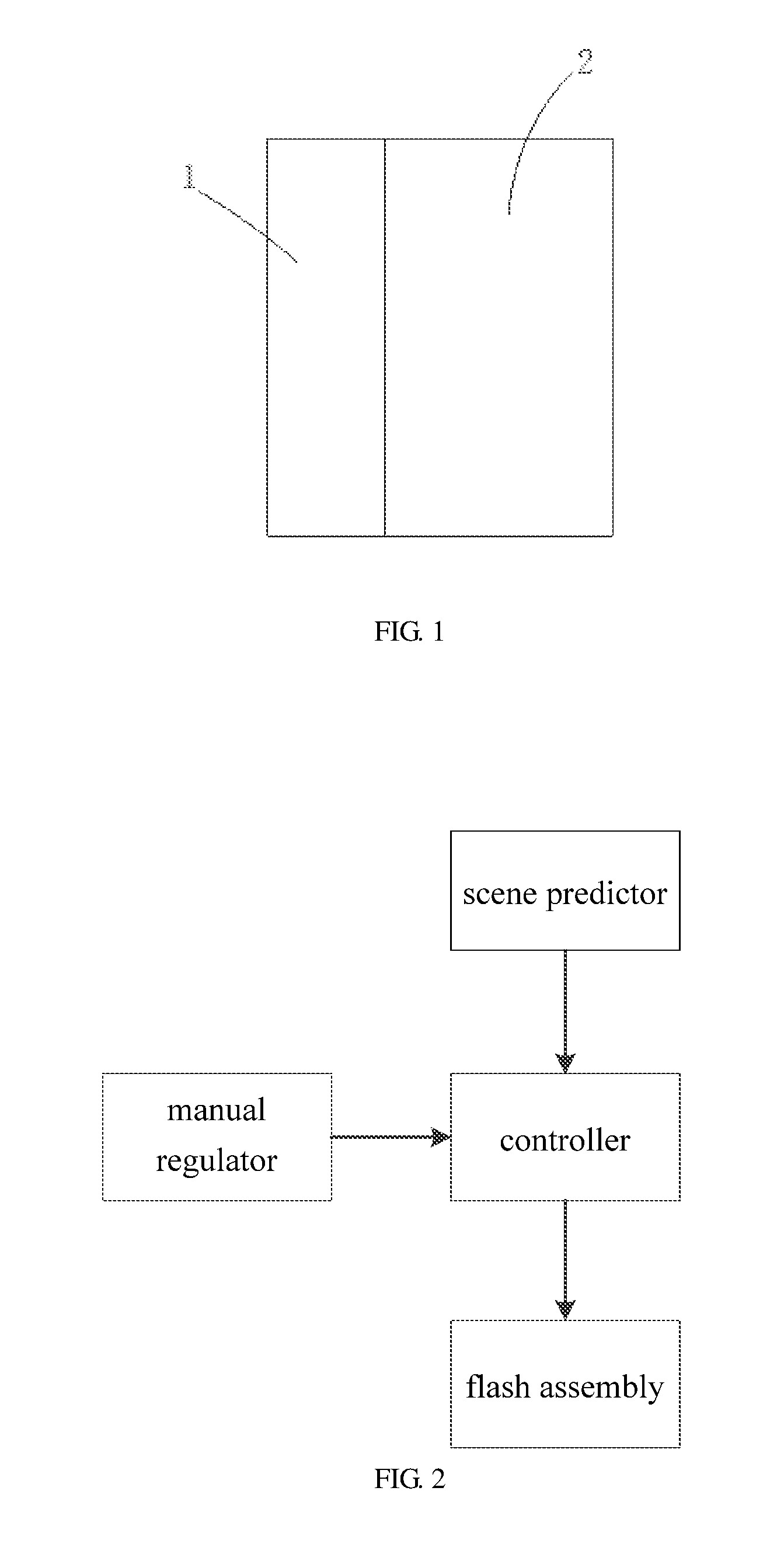
[0030] FIG. 1 is a schematic view of the structure of the present disclosure.
[0031] FIG. 2 is a block diagram of the system of the present disclosure.
[0032] FIG. 3 is a flow diagram of the system of the present disclosure.
[0033] FIG. 4 is a flow diagram of an automatic exposure algorithm of the present disclosure.
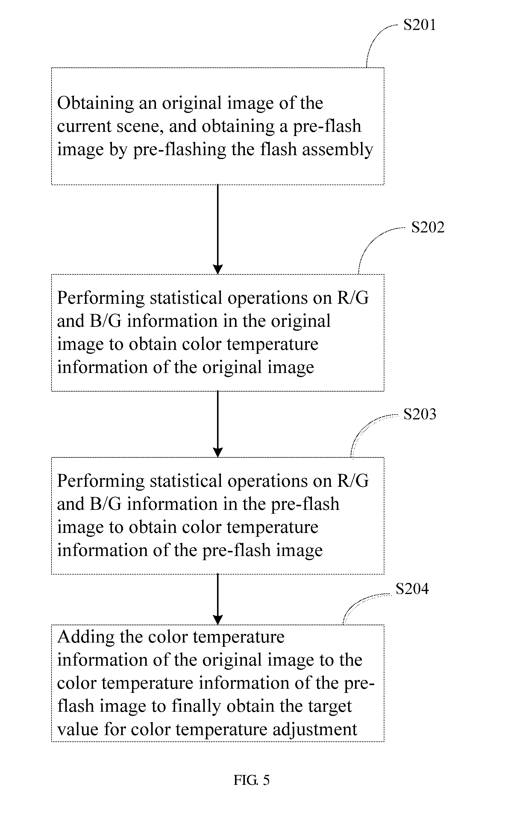
[0034] FIG. 5 is a flow diagram of an automatic white balance algorithm of the present disclosure.
[0035] FIG. 6 is a schematic structural view of an OLED display assembly of the present disclosure.
[0036] FIG. 7 is a schematic structural view showing a specific arrangement position of the display assembly of the present disclosure.
DETAILED DESCRIPTION
[0037] The present disclosure will be further described in detail below with reference to the accompanying drawings and embodiments.
[0038] As shown in FIG. 1, a flash assembly based on a mobile terminal according to the present disclosure may include a flash assembly disposed on the mobile terminal. The flash assembly may be a display assembly 1 disposed at a front end of a camera assembly 2 of the mobile terminal and replacing a protective cover of the existing camera assembly 2. The display assembly 1 may be connected to a processor of the mobile terminal via an I2C. By replacing the flash assembly and the protective cover with the display assembly 1, the present disclosure reduces the number of components and the cost.
[0039] FIG. 7 shows a specific arrangement position of the display assembly, the display assembly 1 may be disposed on a rear housing 3 of the mobile terminal and at a front end of the camera assembly 2 (the dotted portion in the drawing).
[0040] In the embodiments of the present disclosure, the display assembly 1 may be a liquid crystal display assembly, and the liquid crystal display assembly may be an OLED display assembly.
[0041] As shown in FIG. 6, the OLED display assembly of the present disclosure may include a substrate 4 on which an anode 5, a hole transport layer 6, an organic light-emitting layer 7, an electron transport layer 8, and a cathode 9 may be sequentially provided.
[0042] As shown in FIG. 2, a control system based on a mobile terminal may include a flash assembly disposed on the mobile terminal, and the flash assembly may be a display assembly 1 disposed at a front end of a camera assembly. The control system may further include:
[0043] a scene predictor configured to acquire an ambient light color temperature and an ambient light brightness of a current scene through the camera assembly, calculate a focus point, a target value for color temperature adjustment and a target value for brightness adjustment using 3A algorithm, and transmit the focus point, the target value for color temperature adjustment and the target value for brightness adjustment to a controller; and
[0044] the controller configured to calculate correspondingly a shutter speed, a sensitivity of an image sensor of the camera assembly 2, and a current ratio outputted by the flash assembly according to the target value for color temperature adjustment and the target value for brightness adjustment, and to control the display brightness and the display color temperature of the flash assembly via the current ratio outputted by the flash assembly; the flash assembly configured to output a corresponding display brightness and a corresponding display color temperature, which flash assembly is preferably an OLED display assembly.
[0045] The calculation of the shutter speed and the calculation of the sensitivity may be both implemented using the related art, and no specific limitations are set herein.
[0046] The control system of the present disclosure may further include a manual regulator for manually adjusting parameters of the display brightness, the display color temperature, and the flash frequency of the flash assembly and transmitting the parameters to the flash controller, and the controller may output a corresponding current ratio according to the parameters, such that the photo has better performance in the Automatic Exposure (AE) and the Automatic White Balance (AWB).
[0047] The manual regulator may also be used to adjust the display color outputted by the flash assembly, and the controller may adjust a corresponding current ratio according to the desired color, so that the flash assembly displays the corresponding display color, and may function as a flashlight for illumination.
[0048] Referring to FIG. 3, a control method of a flash assembly may include the following blocks:
[0049] Block S01: a scene predictor prejudging an ambient light color temperature and an ambient light brightness of a current scene to obtain data of the same, calculating a focus point, a target value for color temperature adjustment and a target value for brightness adjustment using 3A algorithm, and transmitting the focus point, the target value for color temperature adjustment and the target value for brightness adjustment to a controller.
[0050] Block S02: the controller calculating correspondingly a shutter speed, a sensitivity of a sensor of the camera assembly, and a current ratio outputted by the flash assembly according to the target value for color temperature adjustment and the target value for brightness adjustment.
[0051] Block S03: the flash assembly outputting correspondingly a display color temperature and a display brightness.
[0052] The 3A algorithm may include an automatic focus algorithm (AF), an automatic exposure algorithm (AE), and an automatic white balance algorithm (AWB).
[0053] The automatic focus algorithm (AF) may search for a maximum focus value (FV) in the current scene by adjusting a position of a lens of the camera assembly, and a lens motor drives the lens to a position corresponding to the maximum focus value, thereby completing focusing and determining the focus point.
[0054] As shown in FIG. 4, the automatic exposure algorithm may include the following blocks:
[0055] Block S101: obtaining a pre-flash image by pre-flashing the flash assembly after obtaining an original image of the current scene through the camera assembly.
[0056] Block S102: analyzing the original image to obtain a brightness value (Y) of the original image, and comparing the brightness value (Y) of the original image with a target brightness value (AE target) to obtain an exposure setting value of the original image.
[0057] Block S103: analyzing the pre-flash image to obtain a brightness value (Y) of the pre-flash image, and comparing the brightness value (Y) of the pre-flash image with the target brightness value (AE target) to obtain an exposure setting value of the pre-flash image.
[0058] Block S104: averaging the exposure setting value of the original image and the exposure setting value of the pre-flash image to finally obtain the target value for brightness adjustment.
[0059] The target brightness value (AE target) is typically 47.
[0060] Where the brightness value (Y) of the original image or the pre-flash image is greater than the target brightness value to define an overexposure, the scene predictor decreases the brightness value of the original image or the pre-flash image by the exposure setting value thereof.
[0061] Where the brightness value (Y) of the original image or the pre-flash image is smaller than the target brightness value to define an underexposure, the scene predictor increases the brightness value of the original image or the pre-flash image by the exposure setting value thereof.
[0062] For example, when the original image or the pre-flash image has a brightness value of 30, which is smaller than the target brightness value, the brightness value of the original image or the pre-flash image should be increased by the exposure setting value thereof that is obtained by subtracting the brightness value thereof from 47, namely, the exposure setting value of the original image or the pre-flash image is 17 (47-30=17) in this case; and if the original image or the pre-flash image has a brightness value of 90, the exposure setting value of the original image or pre-flash image is -43 (47-90=-43) in this case.
[0063] As shown in FIG. 5, the automatic white balance algorithm (AWB) may include the following blocks:
[0064] Block S201: obtaining a pre-flash image by pre-flashing the flash assembly 1 after obtaining an original image of the current scene through the camera assembly.
[0065] Block S202: analyzing the original image, and performing statistical operations on R/G and B/G information in the original image to obtain color temperature information of the original image.
[0066] Block S203: analyzing the pre-flash image, and performing statistical operations on R/G and B/G information in the pre-flash image to obtain color temperature information of the pre-flash image.
[0067] Block S204: adding the color temperature information of the original image to the color temperature information of the pre-flash image to finally obtain the target value for color temperature adjustment.
[0068] The statistical operations on the R/G and B/G information in the original image or the pre-flash image specifically include converting the ambient light into an electrical signal via the sensor of the camera assembly, and performing a statistical operation on a value of the electrical signal of each pixel of the Bayer array in the sensor, thereby obtaining the color temperature information of the original image or the pre-flash image; statistical operations on the R/G and B/G information in the original image or the pre-flash image pertain may be the related art, and details thereon is not necessary herein.
[0069] As regards the mainstream display technology for current mobile terminals, the OLED display assembly is superior to the LED flash in terms of luminous efficiency, color and color temperature, and the thermal output of the OLED display assembly is much lower than that of the LED flash, which can reduce the thermal output of the flash. By incorporating and replacing the conventional LED flash and the protective cover of the camera assembly, the present disclosure expands the applications of the display assembly and is able to greatly reduce the cost of production.
[0070] While the present disclosure has been illustrated and described with respect to the specific embodiments, those skilled in the art could appreciate that various changes can be made to the forms and details without departing from the spirit and scope of the present disclosure defined by the appending claims and equivalents thereof.
* * * * *
D00000
D00001
D00002
D00003
D00004
D00005
XML
uspto.report is an independent third-party trademark research tool that is not affiliated, endorsed, or sponsored by the United States Patent and Trademark Office (USPTO) or any other governmental organization. The information provided by uspto.report is based on publicly available data at the time of writing and is intended for informational purposes only.
While we strive to provide accurate and up-to-date information, we do not guarantee the accuracy, completeness, reliability, or suitability of the information displayed on this site. The use of this site is at your own risk. Any reliance you place on such information is therefore strictly at your own risk.
All official trademark data, including owner information, should be verified by visiting the official USPTO website at www.uspto.gov. This site is not intended to replace professional legal advice and should not be used as a substitute for consulting with a legal professional who is knowledgeable about trademark law.