Optical Cable Sealing Method And Optical Cable Sealing Structure
WEN; Jun ; et al.
U.S. patent application number 15/974046 was filed with the patent office on 2019-05-30 for optical cable sealing method and optical cable sealing structure. The applicant listed for this patent is AMPHENOL FIBER OPTIC TECHNOLOGY (SHENZHEN) CO., LTD.. Invention is credited to Shu-Hui HSU, Songsheng LI, Anh NGUYEN, Jun WEN.
| Application Number | 20190162922 15/974046 |
| Document ID | / |
| Family ID | 66591025 |
| Filed Date | 2019-05-30 |


| United States Patent Application | 20190162922 |
| Kind Code | A1 |
| WEN; Jun ; et al. | May 30, 2019 |
OPTICAL CABLE SEALING METHOD AND OPTICAL CABLE SEALING STRUCTURE
Abstract
A method of sealing an optical cable is disclosed. The optical cable includes an outer jacket defining an interior space, an optical fiber assembly disposed in the interior space, and a plurality of reinforcing filaments disposed in the interior space between the outer jacket and the optical fiber assembly. The method includes the steps of peeling off one end of the outer jacket to expose one end of the optical fiber assembly and one ends of the reinforcing filaments, and introducing an adhesive into the interior space through an opening formed in the outer jacket when the one end of the outer jacket is peeled off so as to seal the opening and to fix the positions of the reinforcing filaments and the optical fiber assembly.
| Inventors: | WEN; Jun; (Shenzhen City, CN) ; LI; Songsheng; (Shenzhen City, CN) ; NGUYEN; Anh; (Shenzhen City, CN) ; HSU; Shu-Hui; (Kaohsiung City, TW) | ||||||||||
| Applicant: |
|
||||||||||
|---|---|---|---|---|---|---|---|---|---|---|---|
| Family ID: | 66591025 | ||||||||||
| Appl. No.: | 15/974046 | ||||||||||
| Filed: | May 8, 2018 |
| Current U.S. Class: | 1/1 |
| Current CPC Class: | G02B 6/4476 20130101; G02B 6/4432 20130101; G02B 6/4486 20130101 |
| International Class: | G02B 6/44 20060101 G02B006/44 |
Foreign Application Data
| Date | Code | Application Number |
|---|---|---|
| Nov 30, 2017 | TW | 106141883 |
| Jan 10, 2018 | TW | 107100876 |
Claims
1. A method of sealing an optical cable which includes an outer jacket defining an interior space, an optical fiber assembly disposed in the interior space, and a plurality of reinforcing filaments disposed in the interior space between the outer jacket and the optical fiber assembly, said method comprising: step S1: peeling off one end of the outer jacket to expose one end of the optical fiber assembly and one ends of the reinforcing filaments; and step S2: introducing an adhesive into the interior space through an opening formed in the outer jacket when the one end of the outer jacket is peeled off so as to seal the opening and to fix the positions of the reinforcing filaments and the optical fiber assembly.
2. The method of sealing an optical cable as claimed in claim 1, further comprising: step S3: preparing a reinforcing unit which includes an outer tubular sleeve defining an insertion space, and a plurality of first fiber filaments disposed in the insertion space and having one ends extending out of the insertion space; step S4: inserting the one end of the optical fiber assembly into the insertion space, and connecting the one ends of the first fiber filaments to the one ends of the reinforcing filaments through the adhesive; and step S5: sleeving a heat shrinkable tube on a junction of the optical cable and the reinforcing unit.
3. The method of sealing an optical cable as claimed in claim 2, wherein: the optical fiber assembly includes an inner jacket, at least one optical fiber bundle disposed in the inner jacket, and a plurality of second fiber filaments disposed between the inner jacket and the at least one optical fiber bundle; in step S1, one end of the inner jacket is peeled off to expose one end of the at least one optical fiber bundle and one ends of the second fiber filaments; in step S2, the adhesive fixes the position of the at least one optical fiber bundle and the second fiber filaments; and in step S4, the one end of the at least one optical fiber bundle is inserted into the insertion space, and the one ends of the second fiber filaments are connected to the one ends of the reinforcing filaments and the one ends of the first fiber filaments through the adhesive.
4. An optical cable sealing structure comprising: an optical cable including an outer jacket that defines an interior space and that has two opposite openings communicating with said interior space, an optical fiber assembly disposed in said interior space and having one end extending out of said interior space through one of said openings of said outer jacket, and a plurality of reinforcing filaments disposed in said interior space between said outer jacket and said optical fiber assembly and having one ends extending out of said interior space through said one of said openings of said outer jacket; a reinforcing unit connected to said optical cable and including an outer tubular sleeve that defines an insertion space, and a plurality of first fiber filaments disposed in said insertion space and having one ends extending out of said insertion space, said one end of said optical fiber assembly being inserted into said insertion space and being surrounded by said first fiber filaments; and an adhesive sealing said one of said openings of said outer jacket and connecting said one ends of said reinforcing filaments and said one ends of said first fiber filaments.
5. The optical cable sealing structure as claimed in claim 4, further comprising a heat shrinkable tube sleeved on a junction of said optical cable and said reinforcing unit.
6. The optical cable sealing structure as claimed in claim 4, wherein said optical fiber assembly includes an inner jacket having two opposite openings, at least one optical fiber bundle disposed in said inner jacket and having one end inserted into said insertion space, and a plurality of second fiber filaments disposed between said inner jacket and said at least one optical fiber bundle and having one ends adhered to said adhesive so as to be connected with said one ends of said reinforcing filaments and said one ends of said first fiber filaments.
7. A method of sealing an optical cable which includes an outer jacket defining an interior space, an optical fiber assembly disposed in the interior space, and a plurality of reinforcing filaments disposed in the interior space between the outer jacket and the optical fiber assembly, said method comprising: step A: forming a hole in the outer jacket such that the hole communicates with the interior space; and step B: introducing an adhesive into the interior space through the hole so as to fix the positions of the optical fiber assembly and the reinforcing filaments, to axially block the interior space, and to seal the hole.
8. The method of sealing an optical cable as claimed in claim 7, wherein: the optical fiber assembly includes an inner jacket, at least one optical fiber bundle disposed in the inner jacket, and a plurality of fiber filaments disposed between the inner jacket and the at least one optical fiber bundle; in step A, the inner jacket is formed with a hole facing the hole in the outer jacket; and in step B, the adhesive seals the hole in the inner jacket.
9. The method of sealing an optical cable as claimed in claim 7, further comprising: step C: sleeving a heat shrinkable tube on the outer jacket at a position corresponding to the hole in the outer jacket so as to cover the same.
10. An optical cable sealing structure comprising: an optical cable including an outer jacket that defines an interior space and that is formed with a hole communicating with said interior space, an optical fiber assembly disposed in said interior space, and a plurality of reinforcing filaments disposed in said interior space between said outer jacket and said optical fiber assembly; and an adhesive introduced into said interior space through said hole so as to fix the positions of said optical fiber assembly and said reinforcing filaments, to axially block said interior space, and to seal said hole.
11. The optical cable sealing structure as claimed in claim 10, further comprising a heat shrinkable tube sleeved on said outer jacket and covering said hole.
12. The optical cable sealing structure as claimed in claim 10, wherein said optical fiber assembly includes an inner jacket, at least one optical fiber bundle disposed in said inner jacket, and a plurality of fiber filaments disposed between said inner jacket and said at least one optical fiber bundle, said inner jacket being formed with a hole facing said hole in said outer jacket and sealed by said adhesive.
Description
CROSS-REFERENCE TO RELATED APPLICATION
[0001] This application claims priority of Taiwanese Patent Application No. 106141883, filed on Nov. 30, 2017 and Taiwanese Patent Application No. 107100876, filed on Jan. 10, 2018.
FIELD
[0002] The disclosure relates to an optical cable construction and structure, more particularly to an optical cable sealing method and an optical cable sealing structure.
BACKGROUND
[0003] When an optical cable is disposed in a humid environment, moisture may penetrate the optical cable through one end thereof, thereby affecting the optical fibers inside the optical cable. Moreover, when the optical cable communicates in cooperation with the optical fibers in a vacuum environment, there is also a need to perform a sealing operation on a specific portion of the optical cable to prevent circulation of air through an interior space of the optical cable.
SUMMARY
[0004] Therefore, an object of the present disclosure is to provide a method of sealing an optical cable that can alleviate at least one of the drawbacks of the prior art.
[0005] Accordingly, a method of sealing an optical cable of this disclosure is disclosed. The optical cable includes an outer jacket defining an interior space, an optical fiber assembly disposed in the interior space, and a plurality of reinforcing filaments disposed in the interior space between the outer jacket and the optical fiber assembly. The method includes:
[0006] step S1: peeling off one end of the outer jacket to expose one end of the optical fiber assembly and one ends of the reinforcing filaments; and
[0007] step S2: introducing an adhesive into the interior space through an opening formed in the outer jacket when the one end of the outer jacket is peeled off so as to seal the opening and to fix the positions of the reinforcing filaments and the optical fiber assembly.
[0008] Another object of this disclosure is to provide an optical cable sealing structure that can alleviate at least one of the drawbacks of the prior art.
[0009] Accordingly, an optical cable sealing structure of this disclosure includes an optical cable, a reinforcing unit and an adhesive. The optical cable includes an outer jacket defining an interior space and having two opposite openings communicating with the interior space, an optical fiber assembly disposed in the interior space and having one end extending out of the interior space through one of the openings of the outer jacket, and a plurality of reinforcing filaments disposed in the interior space between the outer jacket and the optical fiber assembly and having one ends extending out of the interior space through the one of the openings of the outer jacket. The reinforcing unit is connected to the optical cable and includes an outer tubular sleeve that defines an insertion space, and a plurality of first fiber filaments disposed in the insertion space and having one ends extending out of the insertion space. The one end of the optical fiber assembly is inserted into the insertion space and is surrounded by the first fiber filaments. The adhesive seals the one of the openings of the outer jacket and connects the one ends of the reinforcing filaments and the one ends of the first fiber filaments.
[0010] Yet another object of this disclosure is to provide a method of sealing an optical cable that can alleviate at least one of the drawbacks of the prior art.
[0011] Accordingly, a method of sealing an optical cable of this disclosure is disclosed. The optical cable includes an outer jacket defining an interior space, an optical fiber assembly disposed in the interior space, and a plurality of reinforcing filaments disposed in the interior space between the outer jacket and the optical fiber assembly. The method includes:
[0012] step A: forming a hole in the outer jacket such that the hole communicates with the interior space; and
[0013] step B: introducing an adhesive into the interior space through the hole so as to fix the positions of the optical fiber assembly and the reinforcing filaments, to axially block the interior space, and to seal the hole.
[0014] Still another object of this disclosure is to provide an optical cable sealing structure that can alleviate at least one of the drawbacks of the prior art.
[0015] Accordingly, an optical cable sealing structure of this disclosure includes an optical cable and an adhesive. The optical cable includes an outer jacket defining an interior space and formed with a hole communicating with the interior space, an optical fiber assembly disposed in the interior space, and a plurality of reinforcing filaments disposed in the interior space between the outer jacket and the optical fiber assembly. The adhesive is introduced into the interior space through the hole so as to fix the positions of the optical fiber assembly and the reinforcing filaments, to axially block the interior space, and to seal the hole.
BRIEF DESCRIPTION OF THE DRAWINGS
[0016] Other features and advantages of the disclosure will become apparent in the following detailed description of the embodiments with reference to the accompanying drawings, of which:
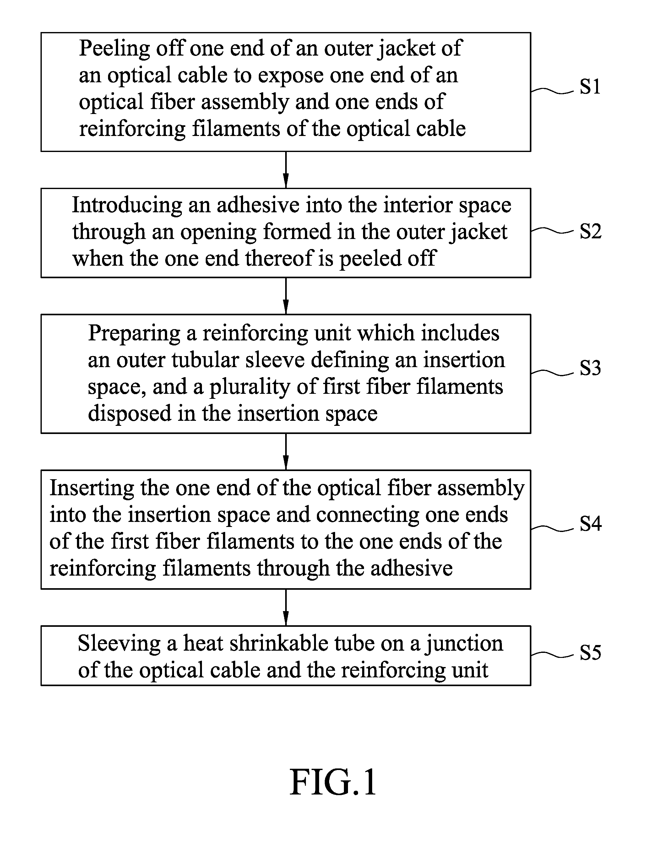
[0017] FIG. 1 is a flow chart, illustrating the steps involved in a method of sealing an optical cable according to the first embodiment of the present disclosure;
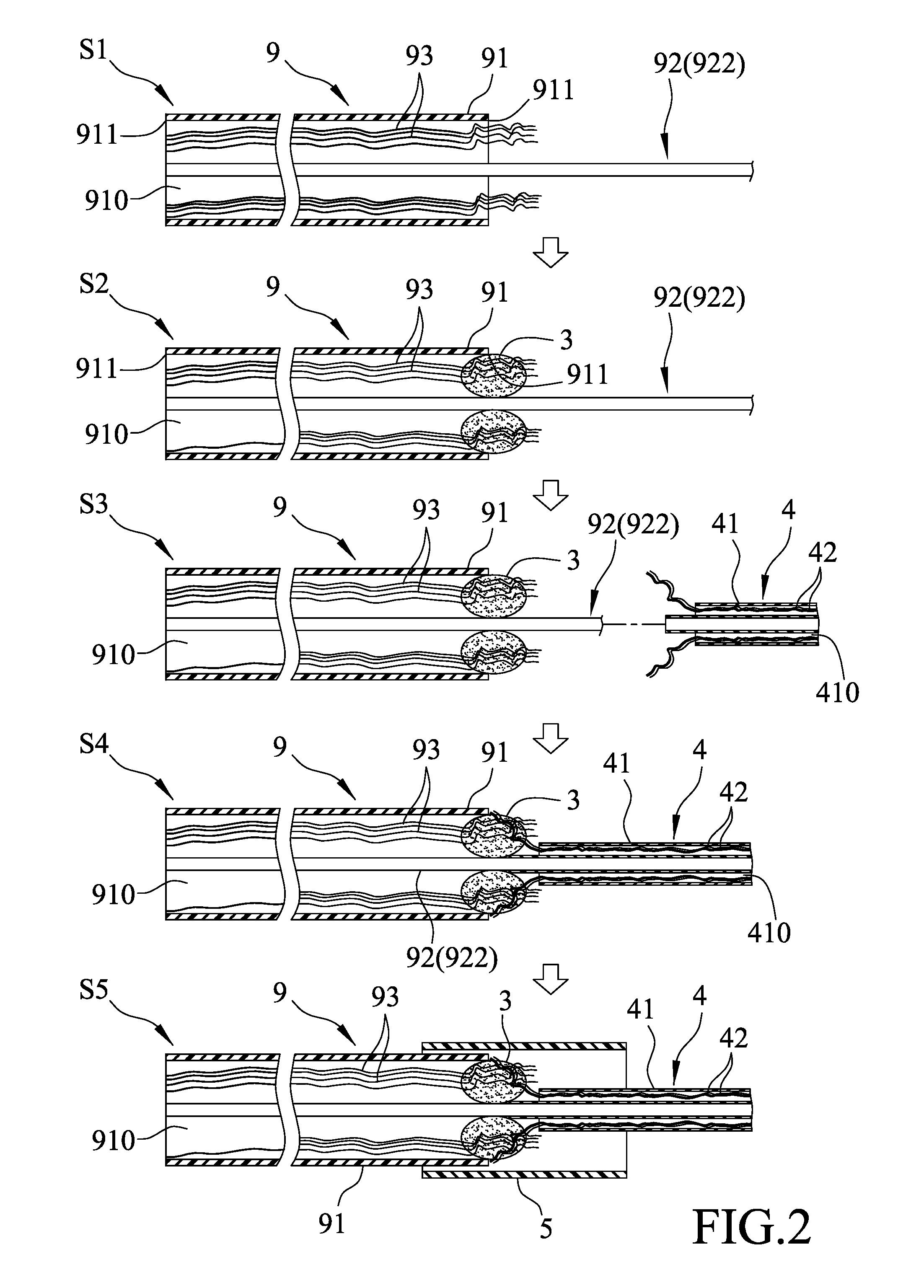
[0018] FIG. 2 illustrates the consecutive steps of the method of the first embodiment;
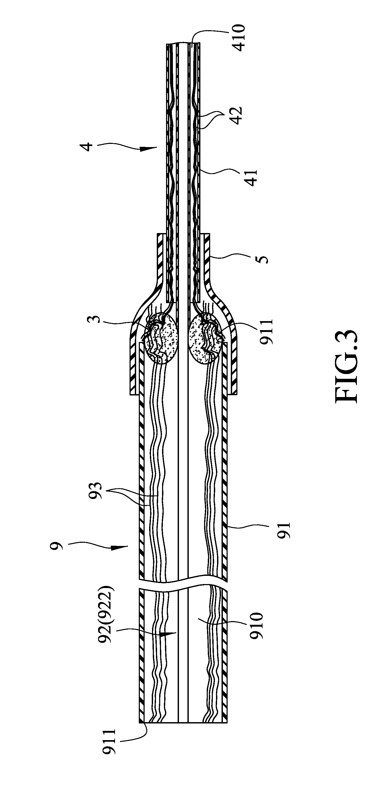
[0019] FIG. 3 is a sectional view of an optical fiber sealing structure of the first embodiment;
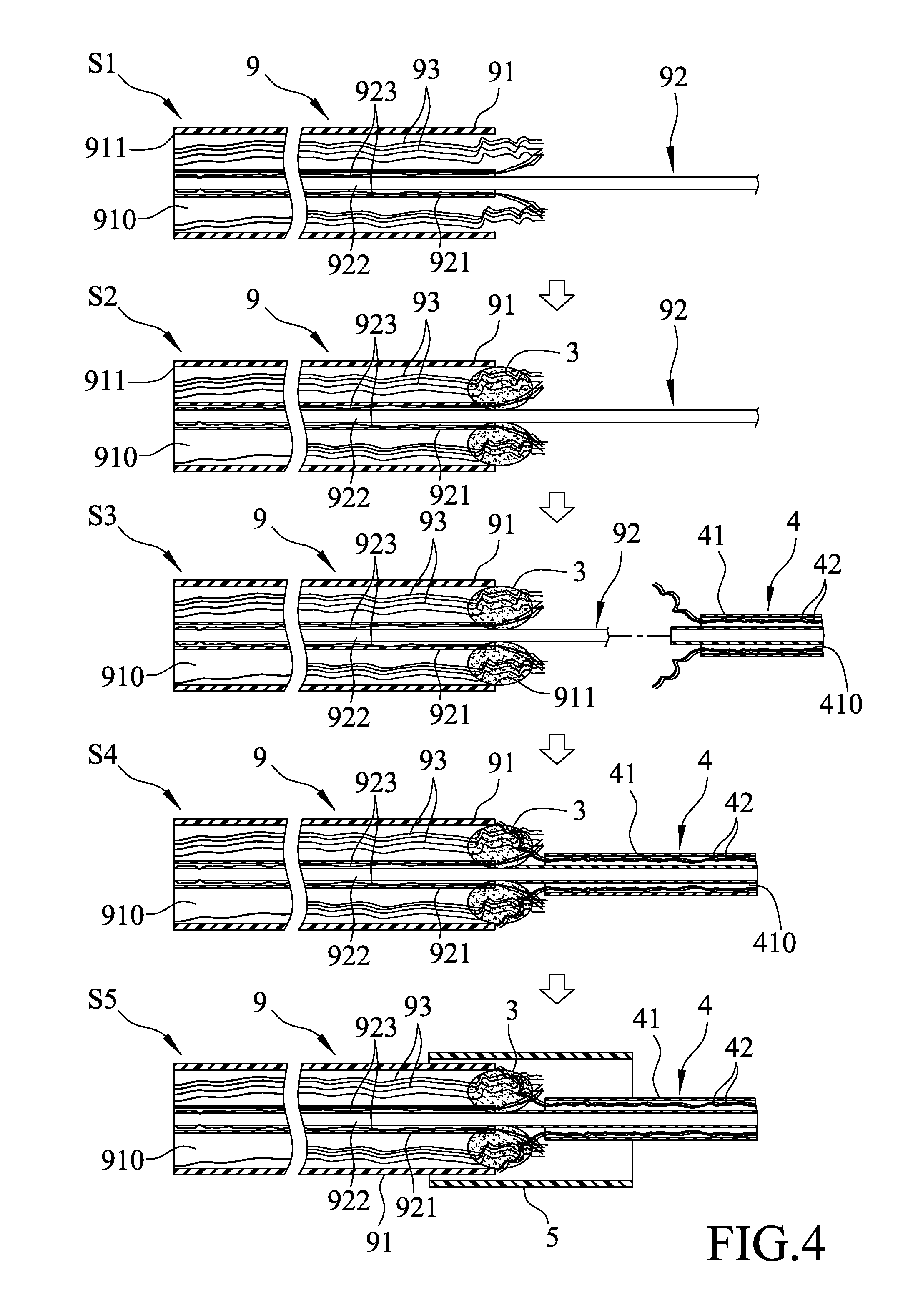
[0020] FIG. 4 illustrates the consecutive steps of a method of sealing an optical cable according to the second embodiment of this disclosure;
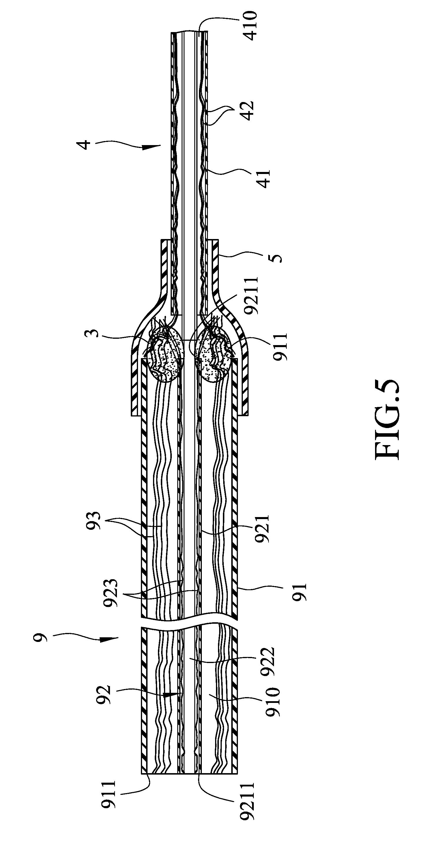
[0021] FIG. 5 is a sectional view of an optical fiber sealing structure of the second embodiment;
[0022] FIG. 6 is a flow chart, illustrating the steps involved in a method of sealing an optical cable according to the third embodiment of the present disclosure;
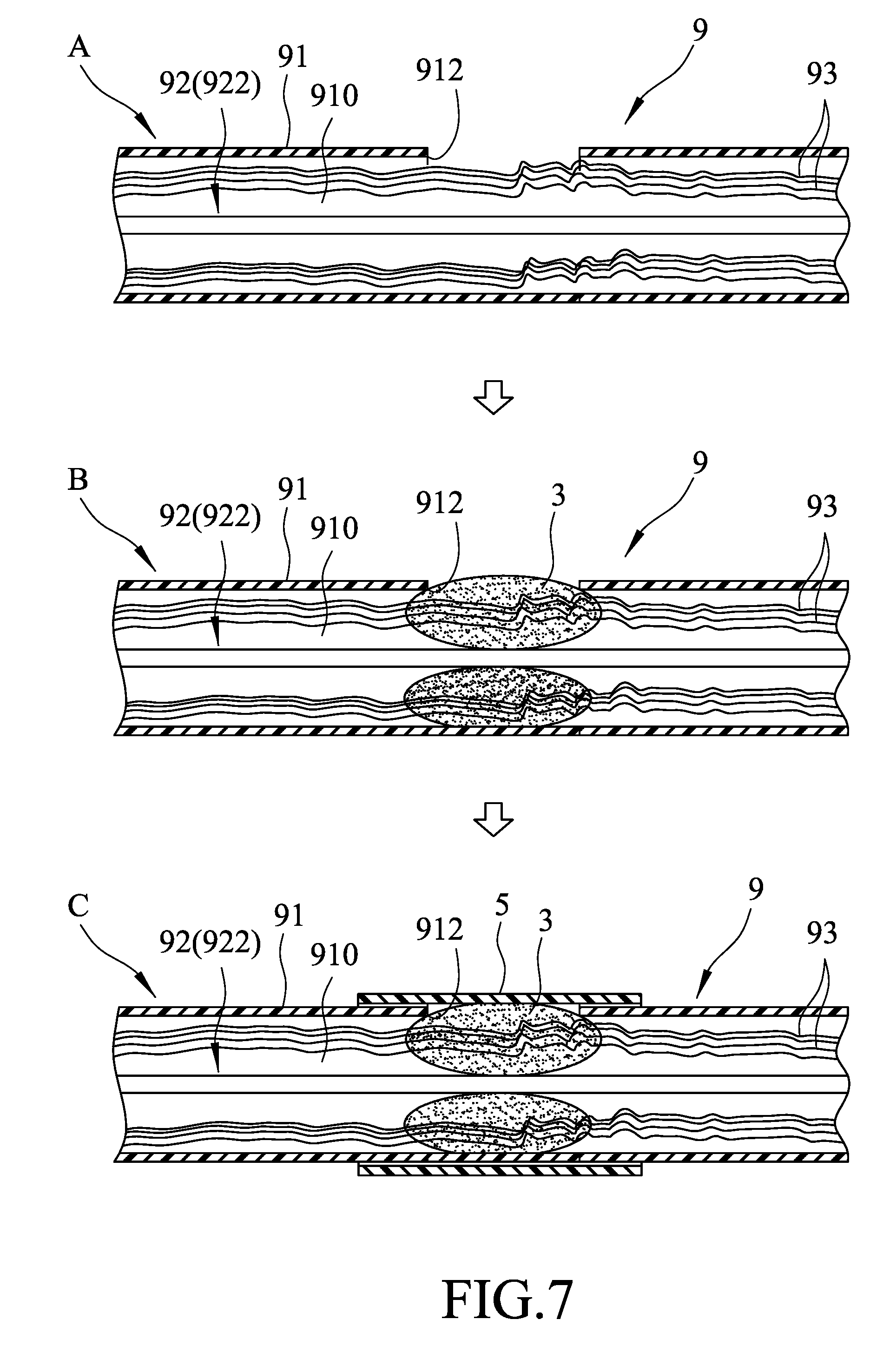
[0023] FIG. 7 illustrates the consecutive steps of the method of the third embodiment;
[0024] FIG. 8 is a sectional view of an optical fiber sealing structure of the third embodiment;
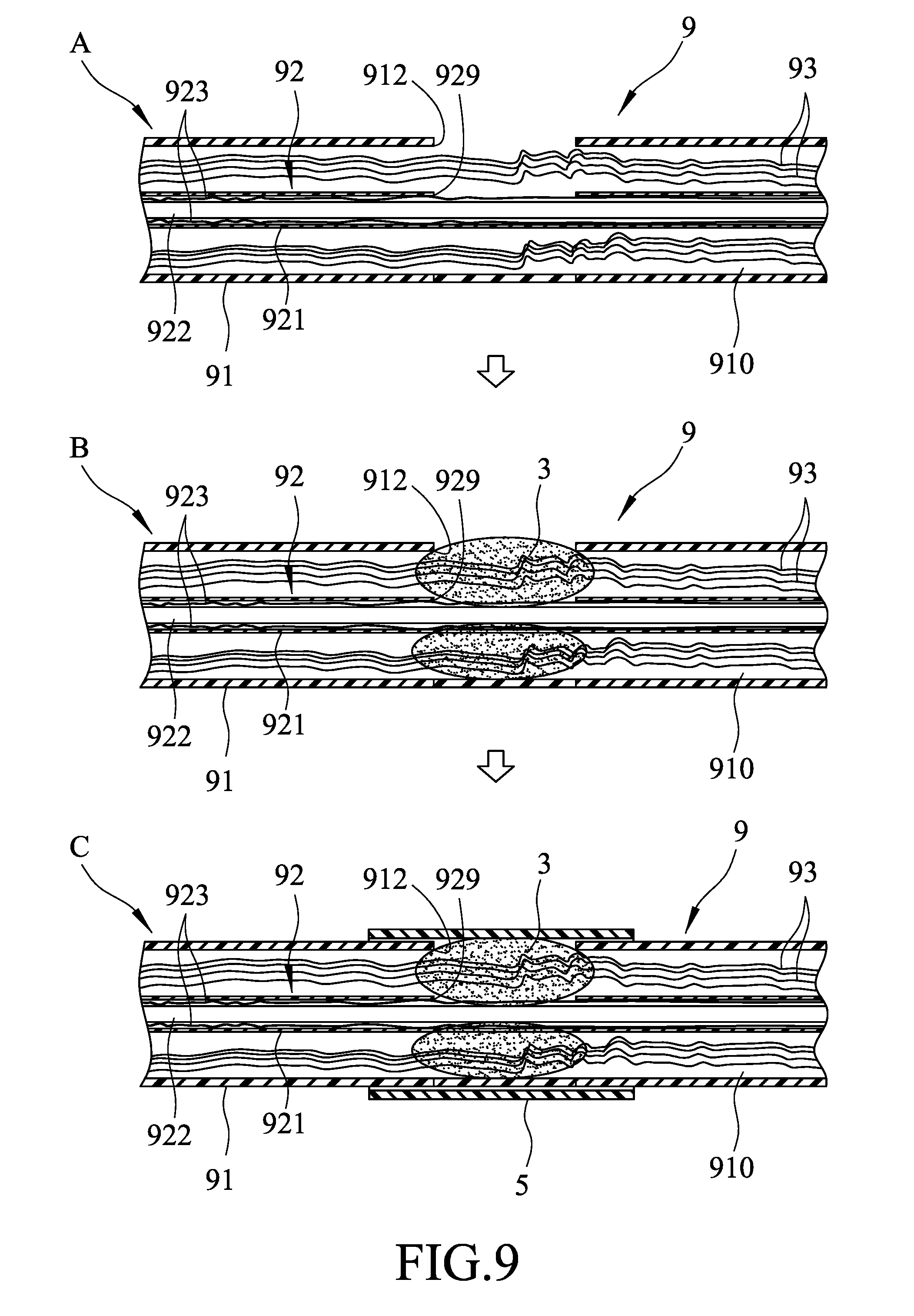
[0025] FIG. 9 illustrates the consecutive steps of a method of sealing an optical cable according to the fourth embodiment of this disclosure; and
[0026] FIG. 10 is a sectional view of an optical fiber sealing structure of the fourth embodiment.
DETAILED DESCRIPTION
[0027] Before the present disclosure is described in greater detail with reference to the accompanying embodiments, it should be noted herein that like elements are denoted by the same reference numerals throughout the disclosure.
[0028] Referring to FIG. 1, a method of sealing an optical cable 9 according to the first embodiment of the present disclosure is shown to include steps S1 to S5. The optical cable 9 includes an outer jacket 91 defining an interior space 910, an optical fiber assembly 92 disposed in the interior space 910, and a plurality of reinforcing filaments 93 disposed in the interior space 910 between the outer jacket 91 and the optical fiber assembly 92. In this embodiment, the optical fiber assembly 92 only includes at least one optical fiber bundle 922. The reinforcing filaments 93 are made of a strong material, and have an effect of protecting the optical fiber assembly 92. Further, through the tensile properties of the reinforcing filaments 93, the reinforcing filaments 93 can provide a supporting effect to reduce the pulling force borne by the optical fiber assembly 92 when the optical cable 9 is pulled. The steps of the method of the first embodiment will be described in combination with FIGS. 2 and 3.
[0029] In step S1, one end of the outer jacket 91 is peeled off in a conventional manner to expose one end of the at least one optical fiber bundle 922 and one ends of the reinforcing filaments 93.
[0030] In step S2, an adhesive 3 is introduced into the interior space 910 through an opening 911 formed in the outer jacket 91 when the one end thereof is peeled off so as to seal the opening 911 and to fix the positions of the at least one optical fiber bundle 922 and the reinforcing filaments 93. The adhesive 3 is preferably made of epoxy resin to achieve a good sealing effect. However, the adhesive 3 may be made of other similar materials, and is not limited to what is disclosed herein.
[0031] In step S3, a reinforcing unit 4 is prepared. The reinforcing unit 4 includes an outer tubular sleeve 41 defining an insertion space 410, and a plurality of first fiber filaments 42 disposed in the insertion space 410 and having one ends extending out of the insertion space 410. The first fiber filaments 42 are made of a material similar that of the reinforcing filaments 93, and have the same effect of protecting internal wires. It should be noted herein that the reinforcing unit 4 is configured to be connected to an electronic device, such as a computer, a television or other telecommunication equipment.
[0032] In step S4, the one end of the at least one optical fiber bundle 922 is inserted into the insertion space 410, and the one ends of the first fiber filaments 42 are connected to the one ends of the reinforcing filaments 93 through the adhesive 3 so that they can protect the at least one optical fiber bundle 922 together.
[0033] In step S5, a heat shrinkable tube 5 is sleeved on a junction of the optical cable 9 and the reinforcing unit 4. The heat shrinkable tube 5 is heated to shrink and clamp the junction of the optical cable 9 and the reinforcing unit 4 to further strengthen the connection between the two. Apart from strengthening the stability of the structure, the heat shrinkable tube 5 can also isolate the adhesive 3 from the external environment to prevent external moisture and air from deteriorating the adhesive 3. An optical cable sealing structure of the first embodiment is completed, as shown in FIG. 3.
[0034] With reference to FIG. 3, in combination with FIG. 2, the optical cable sealing structure of the first embodiment includes the optical cable 9, the reinforcing unit 4, the adhesive 3 and the heat shrinkable tube 5. The outer jacket 91 of the optical cable 9 has two opposite openings 911 communicating with the interior space 910. The at least one optical fiber bundle 922 of the optical fiber assembly 92 has the one end extending out of one of the openings 911, inserted into the insertion space 410 of the outer tubular sleeve 41 of the reinforcing unit 4, and surrounded by the first fiber filaments 42. The reinforcing filaments 93 have the one ends extending out of the one of the openings 911 and fixed to the adhesive 3. The first fiber filaments 42 have the one ends extending out of the insertion space 410 and connected to the one ends of the reinforcing filaments 93 through the adhesive 3. Since the adhesive 3 forms an axial block in the interior space 910, even if there is moisture or other foreign objects, such as dust, enters the interior space 910 through the opening 911 in the outer jacket 91 that is opposite to the adhesive 3, it will still be blocked by the adhesive 3, so that the moisture or dust cannot enter the reinforcing unit 4, thereby protecting the electronic device connected to the reinforcing unit 4. Moreover, the reinforcing unit 4 is sleeved on and covers the one end of the at least one optical fiber bundle 922 exposed from the outer jacket 91 to provide an extra protecting effect and enhance the overall structural strength of the optical cable sealing structure of this disclosure. Finally, through the fixing of the heat shrinkable tube 5 and with the heat shrinkable tube 5 protecting the adhesive 3, the overall structural strength and sealing of the optical cable sealing structure of this disclosure can be further enhanced during use thereof.
[0035] FIG. 4 illustrates the second embodiment of the method of sealing the optical cable 9 of this disclosure. In this embodiment, the optical fiber assembly 92 includes an inner jacket 921, the at least one optical fiber bundle 922 disposed in the inner jacket 921, and a plurality of second fiber filaments 923 disposed between the inner jacket 921 and the at least one optical fiber bundle 922. The method of the second embodiment differs from that of the first embodiment in that:
[0036] in step S1, one end of the inner jacket 921 and one end of the outer jacket 91 are peeled off to expose one ends of the reinforcing filaments 93, one end of the at least one optical fiber bundle 922 and one ends of the second fiber filaments 923;
[0037] in step S2, the adhesive 3 is introduced into the interior space 910 through the opening 911 formed in the outer jacket 91 when the one end thereof is peeled off so as to seal the opening 911 and to fix the positions of the reinforcing filaments 93, the at least one optical fiber bundle 922 and the second fiber filaments 923; and
[0038] in step S4, the one end of the at least one optical fiber bundle 922 is inserted into the insertion space 410 of the outer tubular sleeve 41 of the reinforcing unit 4, and the one ends of the first fiber filaments 42 of the reinforcing unit 4 are connected to the one ends of the reinforcing filaments 93 and the one ends of the second fiber filaments 923 through the adhesive 3. An optical fiber sealing structure of the second embodiment is completed, as shown in FIG. 5.
[0039] With reference to FIG. 5, the optical cable sealing structure of the second embodiment is substantially identical to that of the first embodiment, and differs in that the optical fiber assembly 92 includes the inner jacket 921, the at least one optical fiber bundle 922 disposed in the inner jacket 921, and the second fiber filaments 923 disposed between the inner jacket 921 and the at least one optical fiber bundle 922. The inner jacket 921 has two opposite openings 9211. The at least one optical fiber bundle 922 has one end extending out of one of the openings 9211 and inserted into the insertion space 410 of the outer tubular sleeve 41. The second fiber filaments 923 also have one ends extending out of the one of the openings 9211 and adhered to the adhesive 3 so as to be connected with the one ends of the reinforcing filaments 93 and the one ends of the first fiber filaments 42. The optical cable sealing structure of the second embodiment can achieve the same effect as that of the first embodiment, and the at least one optical fiber bundle 922 can be more completely protected through the inner jacket 921 and the second fiber filaments 923.
[0040] Referring to FIGS. 6 and 7, the third embodiment of the method of sealing the optical cable 9 of this disclosure is shown to include steps A to C. The optical cable 9 of this embodiment is similar to that of the first embodiment, and the optical fiber assembly 92 thereof only includes the at least one optical fiber bundle 922.
[0041] In step A, the outer jacket 91 of the optical cable 9 is formed with a hole 912 such that the hole 912 communicates with the interior space 910 of the outer jacket 91.
[0042] In step B, the adhesive 3 is introduced into the interior space 910 through the hole 912 so as to fix the positions of the at least one optical fiber bundle 922 and the reinforcing filaments 93, to axially block the interior space 910, and to seal the hole 912.
[0043] In step C, the heat shrinkable tube 5 is sleeved on the outer jacket 91 at a position corresponding to the hole 912, and is heated to shrink and clamp the outer jacket 91 so as to cover the hole 912. An optical cable sealing structure of the third embodiment is completed, as shown in FIG. 8.
[0044] With reference to FIG. 8, the optical cable sealing structure of the third embodiment includes the optical cable 9, the adhesive 3, and the heat shrinkable tube 5. Apart from fixing the relative positions of the at least one optical fiber bundle 922 and the reinforcing filaments 93, the adhesive 3 can also form an axial barrier in a central specific area of the interior space 910. The advantage of the third embodiment resides in that a position can be directly selected according to the requirements in which the adhesive 3 can create a barrier so as to match the requirements of the network configuration and use environment.
[0045] FIG. 9 illustrates the fourth embodiment of the method of sealing the optical cable 9 of this disclosure. In this embodiment, the optical fiber assembly 92 includes an inner jacket 921, the at least one optical fiber bundle 922 disposed in the inner jacket 921, and a plurality of second fiber filaments 923 disposed between the inner jacket 921 and the at least one optical fiber bundle 922. The method of the fourth embodiment differs from that of the third embodiment in that:
[0046] in step A, apart from forming the hole 912 in the outer jacket 91 of the optical cable 9, the inner jacket 921 is also formed with a hole 929 facing the hole 912 in the outer jacket 91; and
[0047] in step B, the hole 912 in the outer jacket 91 and the hole 929 in the inner jacket 921 are sealed by the adhesive 3. An optical cable sealing structure of the fourth embodiment is completed, as shown in FIG. 10.
[0048] Apart from achieving the same effect as that of the third embodiment, the optical cable sealing structure of the fourth embodiment can further protect the at least one optical fiber bundle 922 through the inner jacket 921 and the second fiber filaments 923.
[0049] In the description above, for the purposes of explanation, numerous specific details have been set forth in order to provide a thorough understanding of the embodiment(s). It will be apparent, however, to one skilled in the art, that one or more other embodiments may be practiced without some of these specific details. It should also be appreciated that reference throughout this specification to "one embodiment," "an embodiment," an embodiment with an indication of an ordinal number and so forth means that a particular feature, structure, or characteristic may be included in the practice of the disclosure. It should be further appreciated that in the description, various features are sometimes grouped together in a single embodiment, figure, or description thereof for the purpose of streamlining the disclosure and aiding in the understanding of various inventive aspects, and that one or more features or specific details from one embodiment may be practiced together with one or more features or specific details from another embodiment, where appropriate, in the practice of the disclosure.
[0050] While the disclosure has been described in connection with what are considered the exemplary embodiments, it is understood that this disclosure is not limited to the disclosed embodiments but is intended to cover various arrangements included within the spirit and scope of the broadest interpretation so as to encompass all such modifications and equivalent arrangements.
* * * * *
D00000
D00001
D00002
D00003
D00004
D00005
D00006
D00007
D00008
D00009
D00010
XML
uspto.report is an independent third-party trademark research tool that is not affiliated, endorsed, or sponsored by the United States Patent and Trademark Office (USPTO) or any other governmental organization. The information provided by uspto.report is based on publicly available data at the time of writing and is intended for informational purposes only.
While we strive to provide accurate and up-to-date information, we do not guarantee the accuracy, completeness, reliability, or suitability of the information displayed on this site. The use of this site is at your own risk. Any reliance you place on such information is therefore strictly at your own risk.
All official trademark data, including owner information, should be verified by visiting the official USPTO website at www.uspto.gov. This site is not intended to replace professional legal advice and should not be used as a substitute for consulting with a legal professional who is knowledgeable about trademark law.