Microchannel Heat Exchanger
Sathyamurthi; Vijaykumar
U.S. patent application number 15/825201 was filed with the patent office on 2019-05-30 for microchannel heat exchanger. The applicant listed for this patent is Lennox Industries, Inc.. Invention is credited to Vijaykumar Sathyamurthi.
| Application Number | 20190162455 15/825201 |
| Document ID | / |
| Family ID | 64500255 |
| Filed Date | 2019-05-30 |


| United States Patent Application | 20190162455 |
| Kind Code | A1 |
| Sathyamurthi; Vijaykumar | May 30, 2019 |
MICROCHANNEL HEAT EXCHANGER
Abstract
A microchannel heat exchanger includes at least one manifold and at least one a microchannel tube. The microchannel tube includes a plurality of ports, and the microchannel tube extends from the at least one manifold. The plurality of ports each have a width and a height. The microchannel heat exchanger further includes at least one fin extending from the at least one manifold. The fins are arranged between the at least one microchannel tube and a second microchannel tube. The microchannel heat exchanger further includes a refrigerant arranged to flow through the microchannel tube. At least one port of the plurality of ports has a cross-section area less than 0.35 millimeters squared.
| Inventors: | Sathyamurthi; Vijaykumar; (Carrollton, TX) | ||||||||||
| Applicant: |
|
||||||||||
|---|---|---|---|---|---|---|---|---|---|---|---|
| Family ID: | 64500255 | ||||||||||
| Appl. No.: | 15/825201 | ||||||||||
| Filed: | November 29, 2017 |
| Current U.S. Class: | 1/1 |
| Current CPC Class: | F24F 1/18 20130101; F28F 9/0212 20130101; F28F 1/04 20130101; F28D 1/05391 20130101; F28D 1/0426 20130101; F28F 2260/02 20130101; F28F 2210/00 20130101; F28F 9/0243 20130101; F28F 13/00 20130101; F25B 39/04 20130101; F28F 9/0209 20130101; F28F 1/126 20130101; F28D 1/024 20130101; F28D 2021/0068 20130101; F25B 2339/04 20130101; F28F 1/022 20130101 |
| International Class: | F25B 39/04 20060101 F25B039/04; F28F 1/12 20060101 F28F001/12; F28F 1/04 20060101 F28F001/04; F28F 13/00 20060101 F28F013/00 |
Claims
1. A microchannel heat exchanger, comprising: at least one manifold; at least one a microchannel tube comprising a plurality of ports, the at least one microchannel tube extending from the at least one manifold, the plurality of ports each having a width, a height, and a cross-section area; at least one fin extending from the at least one manifold and arranged between the at least one microchannel tube and a second microchannel tube; a refrigerant arranged to flow through the microchannel tube; and wherein at least one port of the plurality of ports has a cross-section area less than 0.35 millimeters squared.
2. The microchannel heat exchanger of claim 1, wherein at least one of the plurality of ports has an aspect ratio greater than 1.5.
3. The microchannel heat exchanger of claim 1, wherein at least one of the plurality of ports has a height less than 0.6 millimeters.
4. The microchannel heat exchanger of claim 1, wherein at least one of the plurality of ports has an aspect ratio of approximately 1.0, a height less than 0.5 millimeters, and a width less than 0.5 millimeters.
5. The microchannel heat exchanger of claim 1, further comprising a fan, the fan arranged to blow air across the at least one fin.
6. The microchannel heat exchanger of claim 1, wherein the at least one manifold is in communication with a heating, ventilation, and air conditioning system.
7. The microchannel heat exchanger of claim 1, comprising a low global warming potential (low-GWP) refrigerant.
8. A condenser, comprising: an enclosure; and a microchannel heat exchanger enclosed within the enclosure, the microchannel heat exchanger comprising: at least one manifold; at least one a microchannel tube comprising a plurality of ports, the at least one microchannel tube extending from the at least one manifold, the plurality of ports each having a width, a height, and a cross-section area; at least one fin extending from the at least one manifold and arranged between the at least one microchannel tube and a second microchannel tube; a refrigerant arranged to flow through the microchannel tube; and wherein at least one port of the plurality of ports has a cross-section area less than 0.35 millimeters squared.
9. The condenser of claim 8, wherein at least one of the plurality of ports has an aspect ratio greater than 1.5.
10. The condenser of claim 8, wherein at least one of the plurality of ports has a height less than 0.6 millimeters.
11. The condenser of claim 8, wherein at least one of the plurality of ports has an aspect ratio of approximately 1.0, a height less than 0.5 millimeters, and a width less than 0.5 millimeters.
12. The condenser of claim 8, further comprising a fan, the fan arranged to blow air across the at least one fin.
13. The condenser of claim 8, wherein the at least one manifold is in communication with a heating, ventilation, and air conditioning system.
14. The condenser of claim 8, comprising a low global warming potential (low-GWP) refrigerant.
15. A heating, ventilation, and air conditioning (HVAC) system, comprising: a condenser; and a microchannel heat exchanger, the microchannel heat exchanger comprising: at least one manifold; at least one a microchannel tube comprising a plurality of ports, the at least one microchannel tube extending from the at least one manifold, the plurality of ports each having a width and a height; at least one fin extending from the at least one manifold and arranged between the at least one microchannel tube and a second microchannel tube; a refrigerant arranged to flow through the microchannel tube; and wherein at least one port of the plurality of ports has a cross-section area less than 0.35 millimeters squared..
16. The HVAC system of claim 15, wherein at least one of the plurality of ports has an aspect ratio greater than 1.5.
17. The HVAC system of claim 15, wherein at least one of the plurality of ports has a height less than 0.6 millimeters.
18. The HVAC system of claim 15, wherein at least one of the plurality of ports has an aspect ratio of approximately 1.0, a height less than 0.5 millimeters, and a width less than 0.5 millimeters.
19. The HVAC system of claim 15, further comprising a fan, the fan arranged to blow air across the at least one fin.
20. The HVAC system of claim 15, further comprising a low global warming potential (low-GWP) refrigerant.
Description
TECHNICAL FIELD
[0001] This disclosure relates generally to a heating, ventilation, and air conditioning (HVAC) system. More specifically, this disclosure relates to an improved microchannel heat exchanger.
BACKGROUND
[0002] HVAC systems can be used to regulate the environment within an enclosed space. Various types of HVAC systems, such as residential and commercial, may be used to provide cool air, for example during hot times of the year, and/or provide heat, for example, during cooler times of the year. Providing heating and/or cooling may be important for user comfort levels. If adequate heating and/or cooling is not provided, a user may be uncomfortable in the enclosed space. In HVAC systems, a condenser cools refrigerant by heat exchange with ambient air drawn or blow across a condenser coil by a fan. Microchannel heat exchangers may be used within the condenser to sufficiently cool the refrigerant. Current microchannel heat exchanger designs are limited.
SUMMARY
[0003] In certain embodiments, a microchannel heat exchanger includes at least one manifold and at least one a microchannel tube. The microchannel tube includes a plurality of ports, and the microchannel tube extends from the at least one manifold. The plurality of ports each have a width and a height. The microchannel heat exchanger further includes at least one fin extending from the at least one manifold. The fins are arranged between the at least one microchannel tube and a second microchannel tube. The microchannel heat exchanger further includes a refrigerant arranged to flow through the microchannel tube. At least one port of the plurality of ports has a cross-section area less than 0.35 millimeters squared.
[0004] In some embodiments, a condenser includes an enclosure and a microchannel heat exchanger enclosed within the enclosure. The microchannel heat exchanger includes at least one manifold and at least one a microchannel tube. The microchannel tube includes a plurality of ports, and the microchannel tube extends from the at least one manifold. The plurality of ports each have a width and a height. The microchannel heat exchanger further includes at least one fin extending from the at least one manifold. The fins are arranged between the at least one microchannel tube and a second microchannel tube. The microchannel heat exchanger further includes a refrigerant arranged to flow through the microchannel tube. At least one port of the plurality of ports has a cross-section area less than 0.35 millimeters squared.
[0005] In certain embodiments, a heating, ventilation, and air conditioning (HVAC) system includes a condenser and a microchannel heat exchanger. The microchannel heat exchanger includes at least one manifold and at least one a microchannel tube. The microchannel tube includes a plurality of ports, and the microchannel tube extends from the at least one manifold. The plurality of ports each have a width and a height. The microchannel heat exchanger further includes at least one fin extending from the at least one manifold. The fins are arranged between the at least one microchannel tube and a second microchannel tube. The microchannel heat exchanger further includes a refrigerant arranged to flow through the microchannel tube. At least one port of the plurality of ports has a cross-section area less than 0.35 millimeters squared.
[0006] Certain embodiments of the present disclosure may provide one or more technical advantages. For example, increasing the aspect ratio of ports of a microchannel tube increases the tubeside heat transfer coefficient, and provides for better cooling for a refrigerant with low global warming potential (low-GWP refrigerant).
[0007] In certain embodiments where the aspect ratios is close to one, the decrease in the cross-section area increases the heat transfer rate due to higher refrigerant velocities.
[0008] In some embodiments, reducing the cross-section area of the ports results in increased heat transfer rates, which are beneficial for low-GWP refrigerants and may reduce the width of the condenser tubes.
[0009] As another example, reducing the port width compared to convention microchannel tubes, and maintaining fixed port height (as shown in FIG. 3B), may allow a low-GWP refrigerant flowing through a microchannel tube to transfer as much or more heat than a conventional refrigerant flowing through a conventional microchannel tube (e.g., in FIG. 3A). Consequently, a condenser with the same or lower size and weight can be used for applications involving the use of low GWP refrigerants.
[0010] As additional example, reducing both the height and the width of the ports of microchannel tubes (e.g., FIG. 3C) reduces the cross-section area of the port, and the refrigerant velocity increases, which increases the tubeside heat transfer coefficient. Another advantage of this embodiment is the reduction in airside pressure drop due to the reduced tube height, resulting in reduced fan power consumption. This embodiment may allow for increased condenser heat rejection per unit area.
[0011] As another example, using smaller ports for microchannel tubes allows a microchannel heat exchanger with a low-GWP refrigerant to maintain the effectiveness of a microchannel heat exchanger with a conventional refrigerant, without increasing the size, weight, cost, or complexity of the microchannel heat exchanger. Certain embodiments of the disclosure may include none, some, or all of the above technical advantages. One or more other technical advantages may be readily apparent to one skilled in the art from the figures, descriptions, and claims included herein. Moreover, while specific advantages have been enumerated above, various embodiments may include all, some, or none of the enumerated advantages.
BRIEF DESCRIPTION OF THE DRAWINGS
[0012] For a more complete understanding of the present disclosure, reference is now made to the following description, taken in conjunction with the accompanying drawings, in which:
[0013] FIG. 1 is a diagram illustrating an example microchannel heat exchanger, according to some embodiments;
[0014] FIG. 2 is a diagram illustrating an example microchannel heat exchanger, according to some embodiments;
[0015] FIGS. 3A, 3B, and 3C illustrate example microchannel tubes, according to some embodiments; and
[0016] FIG. 4 is a diagram illustrating outdoor an HVAC unit comprising a microchannel heat exchanger.
DETAILED DESCRIPTION
[0017] Microchannel heat exchangers may consist of several tubes, with each tube containing multiple ports that the refrigerant may flow through. Traditionally, microchannel heat exchangers have been used with a conventional refrigerant (e.g., hydrofluorocarbons such as R-410A), which have significant global warming potential (GWP) when released into the atmosphere. As companies continue to emphasize global warming mitigation, new refrigerants with low global warming potential (low-GWP refrigerants) are being integrated into existing HVAC systems. HVAC systems may use microchannel heat exchangers as condensers. Due to the poor condensing heat transfer characteristics of low GWP refrigerants, it may be necessary to increase the surface area of the heat exchangers. For example, low-GWP refrigerants may have lower specific heat, lower enthalpy, and/or lower evaporation/condensation heat transfer coefficients. Further, current microchannel heat exchangers have a narrow range of port sizes that are not well suited to these new, low-GWP refrigerants. Thus, heat transfer occurs at a reduced rate in these low-GWP refrigerants. Increasing the size of the microchannel heat exchanger using a low GWP refrigerant, may provide the same system performance as with a conventional refrigerant. However increasing the size further increases cost, expense, and space required to house the microchannel heat exchanger, while further requiring additional fan power consumption, thus reducing the system efficiency. Thus, there is a need for a microchannel heat exchanger design that increases the tubeside heat transfer coefficient, to compensate for the poor thermal properties associated with low-GWP refrigerant.
[0018] This disclosure recognizes that an improved microchannel heat exchanger using refrigerants with poor thermal properties may include an increased number of ports in a microchannel tube, a reduced port hydraulic diameter, a reduced port cross-section area, and an increased aspect ratio of the ports due to reduction in the width. This improved microchannel heat exchanger may facilitate increasing the heat transfer coefficient of the microchannel heat exchanger, in some embodiments. This improvement creates a more compact and efficient microchannel heat exchanger for low-GWP refrigerants.
[0019] Embodiments of the present disclosure and its advantages are best understood by referring to FIGS. 1 through 4 of the drawings, like numerals being used for like and corresponding parts of the various drawings.
[0020] FIG. 1 is a diagram illustrating example microchannel heat exchanger 101 according to some embodiments. Microchannel heat exchanger 101 comprises manifolds 140, a plurality of microchannel tubes 110, and a plurality of fins 120.
[0021] Microchannel heat exchanger 101 comprises manifold 140 and 141. Manifolds 140 and 141 may be in communication with the overall air-conditioning system. Manifold 140 introduces refrigerant to microchannel heat exchanger 101 through inlet tubing (e.g., flow 191) and releases refrigerant from microchannel heat exchanger 101 through outlet tubing (e.g., flow 194). Although manifolds 140 and 141 are shown of a cylindrical configuration, they may be of a rectangular, half of a cylinder or any other shape, as well as have a single chamber or multi-chamber design, depending on the refrigerant path arrangement.
[0022] Microchannel tubes 110 are generally elongated and substantially flat, and extend from one or more manifolds 140, providing a path for refrigerant to flow. Each microchannel tube 110 has a first end mounted to manifold 140 and a second end mounted to manifold 141, and at least one flow channel extending longitudinally, thereby providing a flow path between manifold 140 and manifold 141. Microchannel tubes 110 generally extend in a horizontal direction between manifolds 140, providing a plurality of parallel refrigerant flow paths between manifolds 140. Each microchannel tube 110 may include any number of ports within. In some embodiments, microchannel tubes may be made of aluminum. The heat exchanger refrigerant pass arrangement may be of a multi-pass configuration, such as depicted in FIG. 1, or of a single-pass configuration, depending on particular application requirements.
[0023] A plurality of fins 120 may be arranged between microchannel tubes 110, and parallel to each other. Fins 120 extend from microchannel tubes 110 such that the surface area is increased and configured to transfer heat efficiently. Fins 120 may be straight or angled. Fins 140 may have flat, wavy, corrugated or louvered design and typically form triangular, rectangular, offset or trapezoidal airflow passages. In operation, air may below across fins 120 in order to remove heat from refrigerant flowing through microchannel tubes 110.
[0024] In operation, a refrigerant flows through microchannel tubes 110 in various directions. Refrigerant may be introduced to microchannel heat exchanger 101 at manifold 140 through flow 191. The refrigerant may split such that a portion flows through one or more microchannel tubes 110 until it reaches manifold 140 at flow 192. As it flows through microchannel tubes 110, fins 120 facilitate a heat transfer such that the refrigerant is cooled. The refrigerant continues to flow 193 in manifold 141 where the refrigerant again may split such that a portion flows through one or more microchannel tubes 110 from flow 193 to flow 194 at manifold 140. At flow 194, refrigerant then exits microchannel heat exchanger 101. After completing its flow through microchannel heat exchanger 101 at flow 194, refrigerant may be cooled to a lower temperature than when it entered microchannel heat exchanger 101 at flow 191.
[0025] Modifications, additions, or omissions may be made to the systems described herein without departing from the scope of the disclosure. For example, microchannel heat exchanger 101 may include any number of manifolds 140, microchannel tubes 110, and fins 120. The components may be integrated or separated. Moreover, the operations may be performed by more, fewer, or other components. FIG. 2 is a diagram illustrating example microchannel heat exchanger 201, according to some embodiments. In some embodiments, manifolds 240 and 241 operate as manifolds 140 and 141 of FIG. 1. In some embodiments, microchannel tubes 210 and fins 220 operate as microchannel tubes 110 and fins 120 of FIG. 1. Ports 230 may be individual channels of microchannel tube 210, providing a path for refrigerant to flow through microchannel tube 210 from manifold 240 to manifold 241. Microchannel tubes 210 may include any number of ports 230. As the size of ports 230 varies, the size of microchannel tubes 210 may increase or decrease, thus affecting the number of required microchannel tubes 210 in a microchannel heat exchanger (e.g., microchannel heat exchanger 101 of FIG. 1), in order to sufficiently cool the refrigerant.
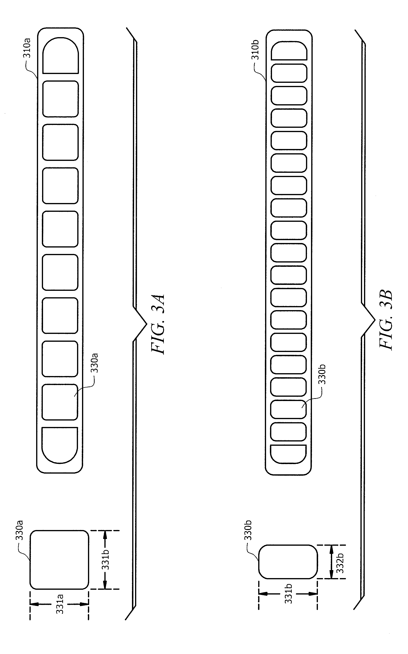
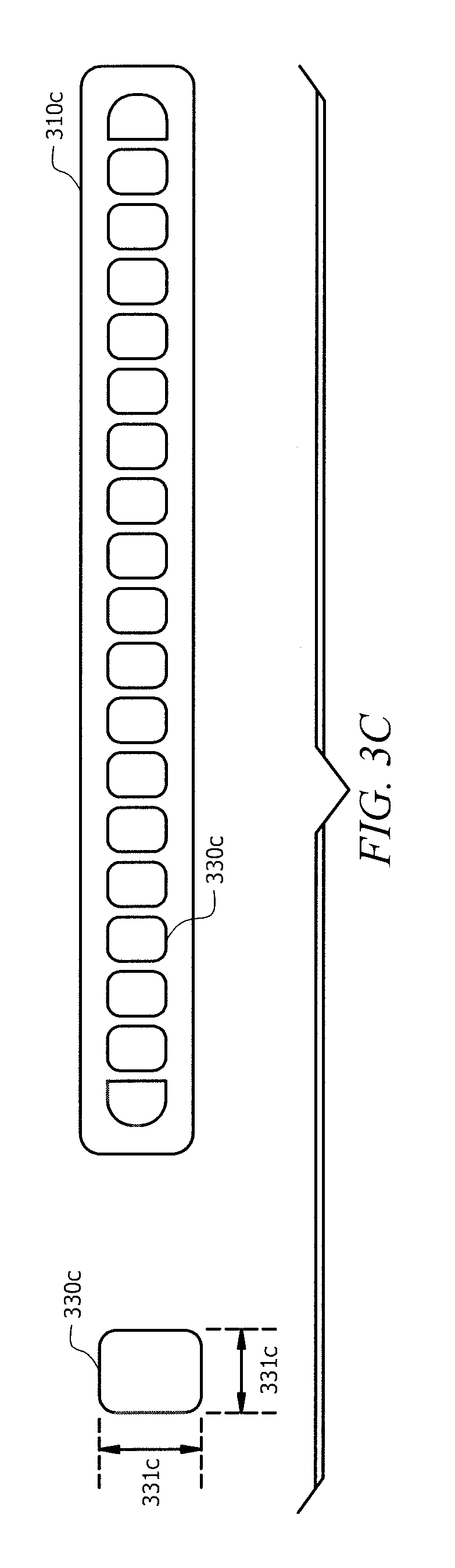
[0026] FIGS. 3A, 3B, and 3C illustrate example microchannel tubes 310a, 310b, and 310c, according to some embodiments. In some embodiments, microchannel tubes 310a-c may be similar to microchannel tubes 110 and 210 of FIG. 1 and FIG. 2, respectively. For example, refrigerant may flow through microchannel tubes 310a-c using ports 330a-c from one manifold to another in order to transfer heat from the refrigerant.
[0027] In FIG. 3A, microchannel tube 310a represents an embodiment used in a microchannel heat exchanger with conventional refrigerant. Port 330a has height 331a and width 331b. The aspect ratio of port 330a is height 331a divided by width 331b. For example, the aspect ratio of port 330 may range from 0.4-1.8, with width 331b ranging from 0.50 mm-1.9 mm, height 331a ranging from 0.50 mm-1.40 mm, and cross-section areas ranging from 0.35 mm.sup.2-1.4 mm.sup.2.
[0028] This disclosure recognizes that an improved microchannel heat exchanger may alter the microchannel ports to provide a more efficient heat transfer. The improved microchannel heat exchanger of this disclosure may reduce the width, height, port cross-section area (i.e. width times height), and/or increased aspect ratio of the ports. In some embodiments, the width of a port may be reduced. In certain embodiments, the height of the port may be reduced. In some embodiments, both the width and the height of the ports may be reduced. Reducing the width, height, or both the width and the height of the ports (e.g., compared to a convention microchannel heat exchanger) creates a smaller cross-section area of the port. This improved microchannel heat exchanger may facilitate increasing the heat transfer coefficient of the microchannel heat exchanger, in some embodiments. This improvement creates a more compact and efficient microchannel heat exchanger for low-GWP refrigerants.
[0029] Reducing the cross-section area of the port in a traditional microchannel heat exchanger would not provide similar benefits when using traditional refrigerants. Microchannel heat exchangers may be air-cooled and therefore may have a high airside thermal resistance. The overall heat transfer coefficient of the microchannel heat exchanger is a function of the airside convection coefficient, which is usually the lowest, the effective conduction heat transfer coefficient, which is typically the highest, and the refrigerant side heat transfer coefficient. Specifically, the heat transfer coefficient for traditional refrigerants is high enough, such that further reduction in the cross-section area of the port would not significantly increase the overall heat transfer coefficient of the traditional microchannel heat exchanger. Further, creating a smaller cross-section area would create a pressure drop, such that the compressor requires more power, and the system efficiency decreases. The improved microchannel heat exchanger of this disclosure uses a refrigerant with low thermal properties and a low heat transfer coefficient. Thus, reducing the cross-section area of the port would provide a significant increase in the heat transfer coefficient, thus resulting in a more compact condenser and providing a more efficient system because the airside pressure drop across the coil is lower, which may reduce the fan power required. FIGS. 3B and 3C illustrate improved microchannel heat exchangers, according to some embodiments. These embodiments are illustrative rather than limiting in nature, and a wide range of variations, modifications, changes, and substitutions may be contemplated.
[0030] In FIG. 3B, microchannel tube 310b may be an embodiment of the present disclosure, where the width of ports may be reduced to compensate for the low-GWP refrigerant's poor thermal qualities. In some embodiments, microchannel tube 310b includes ports 330b. Port 330b may have width 332b ranging from 0.3 mm-0.6 mm and height 331b ranging from 0.3 mm-0.6 mm. Port 330b may include any combination of width 332 and height 331b. In some embodiments, port 330b has a smaller width 332b than width 332a of port 330a, thus creating a more rectangular shape for port 330b than port 330a. For example, port 330b may have width 331b of 0.3 mm, 0.4 mm, or 0.5 mm. In this example, height 331b may remain the same or lesser than the height shown in 331a (e.g., 0.50 mm-1.4 mm). Creating thinner ports 330b increases the number of ports 330b that may fit within microchannel tube 310b. Also, reducing width 331b may increase the aspect ratio of port 330b. In some embodiments, the port cross-section areas are lower than 330a. For example, the aspect ratio of port 330b may be 1.0-1.80 or higher and areas may range between 0.09 mm.sup.2 and 0.25 mm.sup.2. Reducing the cross-section areas of ports 330b may reduce the hydraulic diameter of port 330b, which may increase the tubeside heat transfer coefficient, and provide for better heat transfer with a low-GWP refrigerant. Thus, by reducing width 331b, a low-GWP refrigerant flowing through microchannel tube 310b may transfer as much heat as a conventional refrigerant flowing through microchannel tube 310a.
[0031] In FIG. 3C, microchannel tube 310c may be an embodiment of the present disclosure, where the width and height of ports may be reduced to compensate for the low-GWP refrigerant's poor thermal qualities. In some embodiments, microchannel tube 310b includes ports 330b. Port 330b may have width 332b ranging from 0.3 mm-0.6 mm and height 331b ranging from 0.3 mm-0.6 mm. Port 330b may include any combination of width 332 and height 331b. In some embodiments, port 330c has a smaller width 332c than width 332a of port 330a and a smaller height 331c than height 331a of port 330a. By reducing both height 331c and width 332a of port 330c, the velocity of the refrigerant increases, which may also increase the heat transfer coefficient, and allow the low-GWP refrigerant to cool more quickly. Also, by reducing both height 331c and width 332a of port 330c, additional ports 330c may be included in microchannel tube 310c than microchannel tube 310a. In some embodiments, even when reducing both height 331c and width 332a, port 330c may remain close to a square shape, (e.g., 0.5 mm by 0.5 mm, 0.55 mm by 0.45 mm, 0.29 mm by 0.31 mm), and the aspect ratio of port 330c may remain approximately 1.0 (e.g., 0.8-1.2). By reducing the cross-section area, the velocity of the refrigerant increases, which increases the heat transfer coefficient, and allows the low-GWP refrigerant to cool more quickly. The smaller ports (e.g., ports 330b-c) allow a microchannel heat exchanger with a low-GWP refrigerant to maintain the same effectiveness as a microchannel heat exchanger with a conventional refrigerant without increasing the size, weight, cost, or complexity. In some embodiments, arranging ports 330b and 330c as described in this disclosure would have limited impact on the tubeside resistance of a microchannel heat exchanger using conventional refrigerant. The change in size of ports 330b and 330c from 330a may only increase the heat transfer coefficient of a conventional refrigerant by a nominal amount. In general, air-cooled condensers have a higher heat transfer resistance on the airside. In air-cooled condensers using conventional refrigerants the tubeside resistance is lower, and the air side resistance is dominant, so even if the heat transfer coefficient of the refrigerant is increased slightly, the air cannot absorb enough heat to affect the actual cooling of the conventional refrigerant. However, with low-GWP refrigerants, the tubeside resistance is higher and an increase in the tubeside heat transfer coefficient may greatly impact the actual cooling of the low-GWP refrigerant. Thus, providing ports with higher aspect ratios (e.g., ports 330b), or smaller ports with aspect ratios close to 1.0 (e.g., ports 330c), low-GWP refrigerants may perform cooling as effectively as a conventional refrigerant in the same type and size of microchannel heat exchanger.
[0032] In some embodiments, ports 330c are a smaller size (e.g., compared to ports 330a) such that microchannel tube 310c may also be reduced in height (e.g., compared to the height of microchannel tube 310a). By reducing the height of microchannel tube 310c, microchannel heat exchanger (e.g., microchannel heat exchanger 101 of FIG. 1) may be made with fewer materials, thus conserving resources and expense. By reducing the height of microchannel tube 310c, microchannel heat exchanger (e.g., microchannel heat exchanger 101 of FIG. 1), may include fins (e.g., fins 120 of FIG. 1) with an increased height. Larger fins may increase the surface area on which air is blowing, thus increasing the heat transfer and providing better cooling for the low-GWP refrigerant. Also, by reducing the height of microchannel tube 310c, microchannel heat exchanger (e.g., microchannel heat exchanger 101 of FIG. 1) may include additional tubes (e.g., tubes 110) to create additional pathways for the low-GWP refrigerant to flow through, and thus increasing the amount heat transfer.
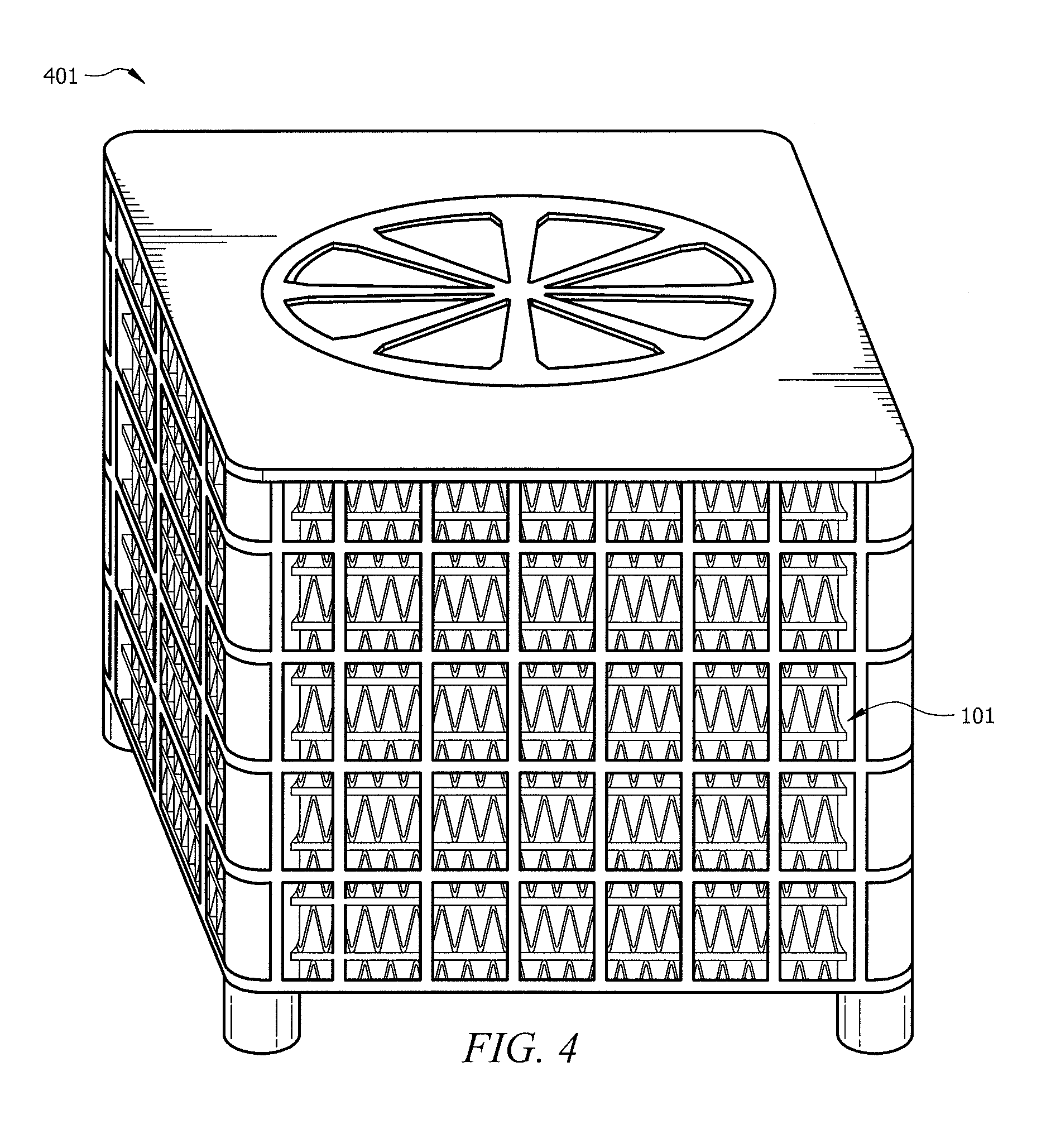
[0033] FIG. 4 is a diagram illustrating outdoor HVAC unit or condenser 401 comprising a microchannel heat exchanger 101 of FIG. 1. Outdoor unit 401 may encase microchannel heat exchanger 101 in an enclosure such that it is protected from an external environment. In some embodiments, outdoor unit 401 may further comprise fan 405. Fan 405 may direct a flow of air across microchannel heat exchanger. Fan 405 provides air flow to microchannel heat exchanger 101 to facilitate cooling the refrigerant flowing through microchannel heat exchanger 101. Any number of fans may be included.
[0034] In some embodiments, microchannel heat exchanger 101 may incorporate ports 330b and/or 330c from FIG. 3. By incorporating smaller ports 330b and/or 330c than ports 330a, heat is transferred from the low-GWP refrigerant more efficiently. Thus, fan 405 may consume less power for a given air flow. With fan 405 consuming less power, outdoor HVAC unit 401 operates more efficiently, and conserves resources.
[0035] Modifications, additions, or omissions may be made to the systems, apparatuses, and methods described herein without departing from the scope of the disclosure. The components of the systems and apparatuses may be integrated or separated. Moreover, the operations of the systems and apparatuses may be performed by more, fewer, or other components. For example, microchannel heat exchanger 101 may include any number of microchannel tubes 110, fins 120, manifolds 140 and 141, and so on, as performance demands dictate. One skilled in the art will also understand that microchannel heat exchanger 101 and outdoor HVAC unit 401 can include other components that are not illustrated but are typically included with HVAC systems.
[0036] Although this disclosure has been described in terms of certain embodiments, alterations and permutations of the embodiments will be apparent to those skilled in the art, and it is intended that the present disclosure encompass such changes, variations, alterations, transformations, and modifications as fall within the scope of the appended claims. Accordingly, the above description of the embodiments does not constrain this disclosure. Other changes, substitutions, and alterations are possible without departing from the spirit and scope of this disclosure.
* * * * *
D00000
D00001
D00002
D00003
D00004
D00005
XML
uspto.report is an independent third-party trademark research tool that is not affiliated, endorsed, or sponsored by the United States Patent and Trademark Office (USPTO) or any other governmental organization. The information provided by uspto.report is based on publicly available data at the time of writing and is intended for informational purposes only.
While we strive to provide accurate and up-to-date information, we do not guarantee the accuracy, completeness, reliability, or suitability of the information displayed on this site. The use of this site is at your own risk. Any reliance you place on such information is therefore strictly at your own risk.
All official trademark data, including owner information, should be verified by visiting the official USPTO website at www.uspto.gov. This site is not intended to replace professional legal advice and should not be used as a substitute for consulting with a legal professional who is knowledgeable about trademark law.