Dehumidifier
KIM; Minhwan ; et al.
U.S. patent application number 16/201662 was filed with the patent office on 2019-05-30 for dehumidifier. The applicant listed for this patent is LG Electronics Inc.. Invention is credited to Jaeyoung Kim, Minhwan KIM, Sehyeon Kim, Yohan Lee.
| Application Number | 20190162432 16/201662 |
| Document ID | / |
| Family ID | 66633968 |
| Filed Date | 2019-05-30 |


View All Diagrams
| United States Patent Application | 20190162432 |
| Kind Code | A1 |
| KIM; Minhwan ; et al. | May 30, 2019 |
DEHUMIDIFIER
Abstract
A dehumidifier including a condenser configured to condense a refrigerant, an evaporator configured to evaporate the refrigerant, and a heat transfer module configured to absorb heat from air flowing into the evaporator and to transfer the heat to air discharged from the evaporator, wherein the heat transfer module includes a right module enclosing a right side of the evaporator and a left module enclosing a left side of the evaporator, whereby each of the right module and the left module includes a plurality of side heat pipes formed in a U shape to seal a fluid therein, the plurality of side heat pipes being vertically arranged; and a plurality of side cooling fins connected to the plurality of side heat pipes and horizontally arranged.
| Inventors: | KIM; Minhwan; (Seoul, KR) ; Kim; Sehyeon; (Seoul, KR) ; Kim; Jaeyoung; (Seoul, KR) ; Lee; Yohan; (Seoul, KR) | ||||||||||
| Applicant: |
|
||||||||||
|---|---|---|---|---|---|---|---|---|---|---|---|
| Family ID: | 66633968 | ||||||||||
| Appl. No.: | 16/201662 | ||||||||||
| Filed: | November 27, 2018 |
| Current U.S. Class: | 1/1 |
| Current CPC Class: | F24F 3/153 20130101; F24F 13/30 20130101; F24F 2003/1446 20130101 |
| International Class: | F24F 3/153 20060101 F24F003/153; F24F 13/30 20060101 F24F013/30 |
Foreign Application Data
| Date | Code | Application Number |
|---|---|---|
| Nov 28, 2017 | KR | 10-2017-0160861 |
Claims
1. A dehumidifier comprising: a condenser configured to condense a refrigerant; an evaporator configured to evaporate the refrigerant; and a heat transfer module configured to absorb heat from air flowing into the evaporator, and to transfer the heat to air discharged from the evaporator, wherein the heat transfer module comprises: a right module enclosing a right side of the evaporator; and a left module enclosing a left side of the evaporator, wherein the right module and the left module each comprises: a plurality of side heat pipes that are vertically arranged relative to a direction of gravity, each of the side heat pipes having a U shape to seal a fluid therein; and a plurality of side cooling fins connected to the plurality of side heat pipes and are horizontally arranged.
2. The dehumidifier of claim 1, wherein each of the plurality of side cooling fins is formed as a corrugated fin.
3. The dehumidifier of claim 1, wherein each of the plurality of side cooling fins is formed as a slit fin having a surface that is partially cut and bent in an upward direction.
4. The dehumidifier of claim 1, wherein the heat transfer module further comprises: a plurality of middle section modules disposed at a middle portion of the heat transfer module between a front surface and a rear surface of the evaporator, to connect the right module with the left module.
5. The dehumidifier of claim 4, wherein each of the middle section modules comprises a plurality of connection holes that are vertically arranged and configured to receive end portions of the plurality of side heat pipes of the right module and the left module.
6. The dehumidifier of claim 4, wherein each of the middle section modules comprises: a plurality of sleeves that are vertically arranged, each of which is formed in a tubular shape and configured to receive end portions of the plurality of side heat pipes of the right module and the left module; and a plurality of dummy fins that are horizontally arranged and connected to the plurality of sleeves.
7. The dehumidifier of claim 6, wherein each of the plurality of dummy fins has the same shape as each of the plurality of side cooling fins.
8. The dehumidifier of claim 4, wherein each of the middle section modules comprises: a plurality of center heat pipes that are horizontally arranged, each of which is configured to seal a fluid therein; and a plurality of center cooling pipes that are vertically arranged and connected to the plurality of center heat pipes.
9. The dehumidifier of claim 1, wherein each of the middle section modules further comprises a plurality of coupling frames, each of which has a square rim shape, formed on all sides of the plurality of center cooling fins, and configured to receive the end portions of the plurality of side heat pipes of the right module and the left module.
10. The dehumidifier of claim 4, wherein the middle section module comprises: an upper module enclosing an upper portion of the evaporator; and a lower module enclosing a lower portion of the evaporator.
11. A dehumidifier comprising: a condenser configured to condense a refrigerant; an evaporator configured to evaporate the refrigerant; and a heat transfer module configured to absorb heat from air flowing into the evaporator, and to transfer the heat to air discharged from the evaporator, wherein the heat transfer module comprises: a right module enclosing a right side of the evaporator; and a left module enclosing a left side of the evaporator, wherein each of the right module and the left module comprises: a plurality of side heat pipes each comprising two straight line parts, which extend in a left and right direction of the heat transfer module and are spaced apart from each other in a front and rear direction or the heat transfer module, and a connection part that connects the two straight line parts; and a plurality of side cooling fins connected to the plurality of side heat pipes and spaced apart from each other in the left and right direction.
12. The dehumidifier of claim 11, wherein each of the plurality of side cooling fins is connected to the two straight line parts.
13. The dehumidifier of claim 11, wherein one of the two straight line parts is disposed at a front side of the evaporator, and the other one of the two straight line parts is disposed at a rear side of the evaporator.
14. The dehumidifier of claim 11, wherein the connection part is disposed on at least one of a left side and a right side of the evaporator.
15. The dehumidifier of claim 11, wherein the heat transfer module further comprises a plurality of middle section modules that are disposed at a middle portion thereof between a front surface and a rear surface of the evaporator, to connect the right module with the left module.
16. The dehumidifier of claim 15, wherein each of the middle section modules includes a plurality of connection holes that are vertically formed and configured to receive end portions of the plurality of side heat pipes of the right module and the left module.
17. The dehumidifier of claim 15, wherein each of the middle section modules comprises: a plurality of sleeves that are vertically arranged, each of which is formed in a tubular shape and configured to receive end portions of the plurality of side heat pipes of the right module and the left module; and a plurality of dummy fins that are horizontally arranged and connected to the plurality of sleeves.
18. The dehumidifier of claim 15, wherein each of the plurality of dummy fins has the same shape as each of the plurality of side cooling fins.
19. The dehumidifier of claim 15, wherein each of the middle section modules comprises: a plurality of center heat pipes that are horizontally arranged, each of which is configured to seal a fluid therein; and a plurality of center cooling pipes that are vertically arranged and connected to the plurality of center heat pipes.
20. The dehumidifier of claim 19, wherein each of the middle section modules comprises a plurality of coupling frames, each of which has a square rim shape, formed on all sides of the plurality of center cooling fins, and configured to receive the end portions of the plurality of side heat pipes of the right module and the left module.
Description
CROSS-REFERENCE TO RELATED APPLICATIONS
[0001] The present application claims priority under 35 U.S.C. .sctn. 119 and 35 U.S.C. .sctn. 365 to Korean Patent Application No. 10-2017-0160861, filed on Nov. 28, 2017, which is hereby incorporated by reference in its entirety.
BACKGROUND OF THE INVENTION
1. Field of the Invention
[0002] The present disclosure relates generally to a dehumidifier, and more particularly to a dehumidifier to perform dehumidification using a refrigeration cycle.
2. Description of the Related Art
[0003] A dehumidifier is a home appliance which reduces and maintains the level of humidity in the air for household, commercial, or industrial applications. More particularly, the humidifier removes moisture from the air, and then discharges the dehumidified air to maintain the air dry. Examples of the dehumidifier include: a spray dehumidifier using sprayed water; a desiccant dehumidifier using a moisture absorbing material; and a mechanical dehumidifier using a refrigeration cycle.
[0004] The mechanical dehumidifier performs dehumidification by condensing moisture when air passes through an evaporator. The air, having passed through the evaporator, passes through a condenser to be reheated. Cooling the air is not the purpose of the dehumidifier, such that it is only needed to reduce the temperature of air to a dew point. However, performance of the refrigeration cycle is designed at a level which allows air to be sufficiently cooled under high temperature and humidity conditions, such that air may be cooled more than necessary (and may cool a room or specific space). By contrast, in the case of reducing the temperature of air flowing into the evaporator, the air temperature, which is to be reduced to a dew point in the evaporator, may be lowered. Accordingly, the present invention constitutes a heat transfer module, which transfers cooled air, having passed through the evaporator, to air flowing into the evaporator.
SUMMARY OF THE INVENTION
[0005] The foregoing embodiments provide a dehumidifier which may reduce load on an evaporator by using a heat pipe type heat transfer module having an integrally formed fin.
[0006] According to one embodiment, the above object can be accomplished by providing a dehumidifier, including: a condenser configured to condense a refrigerant; an evaporator configured to evaporate the refrigerant; and a heat transfer module configured to absorb heat from air flowing into the evaporator, and to transfer the heat to air discharged from the evaporator. The heat transfer module may be divided into: a right module enclosing a right side of the evaporator; and a left module enclosing a left side of the evaporator, wherein each of the right module and the left module may include: a plurality of side heat pipes which are formed in a U shape to seal a fluid therein, and are vertically arranged; and a plurality of side cooling fins which are connected to the plurality of side heat pipes and are horizontally arranged, thereby improving heat transport efficiency.
[0007] Each of the plurality of side cooling fins may be a corrugated fin.
[0008] Each of the plurality of side cooling fins may be a slit fin having a surface which is partially cut and bent upward.
[0009] The heat transfer module may further include a plurality of middle section modules which are disposed at a middle portion between a front surface and a rear surface of the evaporator, to connect a left end of the right module and a right end of the left module.
[0010] The middle section modules, which are formed in a vertically long plate shape, may include a plurality of connection holes which are vertically formed, and into which end portions of the plurality of side heat pipes of the right module and the left module are inserted.
[0011] Each of the middle section module may include: a plurality of sleeves, each of which is formed in a tubular shape and has both sides, into which end portions of the plurality of side heat pipes of the right module and the left module are inserted, and are vertically arranged; and a plurality of dummy fins which are connected to the plurality of sleeves and are horizontally arranged.
[0012] Each of the plurality of dummy fins may have the same shape as each of the plurality of side cooling fins.
[0013] Each of the middle section modules may include: a plurality of center heat pipes, each of which includes a fluid sealed therein, and which are horizontally arranged; and a plurality of center cooling pipes which are connected to the plurality of center heat pipes and are vertically arranged.
[0014] Each of the middle section modules may further include a plurality of coupling frames, each of which has a square rim shape, to be formed on all sides, including top, bottom, left, and right sides, of the plurality of center cooling fins, and has both sides into which the end portions of the plurality of side heat pipes of the right module and the left module are inserted.
[0015] The middle section module may include: an upper module enclosing an upper portion of the evaporator; and a lower module enclosing a lower portion of the evaporator.
[0016] According to another embodiment, the above object can be accomplished by providing a dehumidifier, including: a condenser configured to condense a refrigerant; an evaporator configured to evaporate the refrigerant; and a heat transfer module configured to absorb heat from air flowing into the evaporator, and to transfer the heat to air discharged from the evaporator, wherein the heat transfer module includes: a right module enclosing a right side of the evaporator; and a left module enclosing a left side of the evaporator, wherein each of the right module and the left module includes: a plurality of side heat pipes including two straight line parts, which are extended in a left and right direction and are spaced apart from each other in a front and rear direction, and a connection part which connects the two straight line parts; and a plurality of side cooling fins which are connected to the plurality of side heat pipes and are spaced apart from each other in the left and right direction.
[0017] Each of the plurality of side cooling fins may be connected to the two straight line parts.
[0018] One of the two straight line parts may be disposed on a front side of the evaporator, and the other one may be disposed on a rear side of the evaporator.
[0019] The connection part may be disposed on at least one of a left side and a right side of the evaporator.
[0020] Details of other exemplary embodiments are included in the detailed description and drawings.
[0021] As is apparent from the above description, the dehumidifier according to embodiments of the present disclosure has one or more of the following desirous effects.
[0022] First, by dividing the heat pipe type heat transfer module having an integrally formed fin, heat transport efficiency may be improved.
[0023] Second, the heat transfer module is divided into a right module and a left module, thereby enabling efficient arrangement with an evaporator.
[0024] Third, by providing a middle section module for connecting the divided heat transfer module, modules may be connected efficiently without disrupting the air flow.
[0025] The advantageous effects of the present disclosure are not limited to the above, and other effects not described above will become apparent to those skilled in the art from the following description.
BRIEF DESCRIPTION OF THE DRAWINGS
[0026] To achieve the foregoing objects, and in accordance with the purpose of the invention as embodied and broadly described herein.
[0027] FIG. 1 is a structural view illustrating a dehumidifier according to an embodiment of the present invention.
[0028] FIG. 2 is a perspective view of a heat transfer module according to an embodiment of the present invention.
[0029] FIG. 3 is a partial structural view of the heat transfer module illustrated in FIG. 2.
[0030] FIG. 4 is a perspective view of a heat transfer module according to another embodiment of the present invention.
[0031] FIG. 5 is a partial structural view of the heat transfer module illustrated in FIG. 4.
[0032] FIG. 6 is a perspective view of a heat transfer module according to yet another embodiment of the present invention.
[0033] FIG. 7 is a partial structural view of the heat transfer module illustrated in FIG. 6.
[0034] FIG. 8 is a perspective view of a heat transfer module according to still another embodiment of the present invention.
[0035] FIG. 9 is a partial structural view of the heat transfer module illustrated in FIG. 8.
[0036] FIG. 10 is a partial structural view of a heat transfer module according to still another embodiment of the present invention.
[0037] FIG. 11 is a partial structural view of a heat transfer module according to still another embodiment of the present invention.
DETAILED DESCRIPTION OF THE PREFERRED EMBODIMENTS
[0038] Hereinafter, embodiments of the present invention will be described in detail with reference to the accompanying drawings.
[0039] It will nevertheless be understood that no limitation of the scope of the invention is thereby intended. Alterations and further modifications of the inventive features illustrated here, and additional applications of the principles of the inventions as illustrated here, which would occur to a person skilled in the relevant art and having possession of this disclosure, are to be considered within the scope of the invention.
[0040] The meaning of terms is clarified in this disclosure, so the claims should be read with careful attention to these clarifications. Specific examples are given, but those of skill in the relevant art(s) will understand that other examples may also fall within the meaning of the terms used, and within the scope of one or more claims. Terms do not necessarily have the same meaning here that they have in general usage (particularly in non-technical usage), or in the usage of a particular industry, or in a particular dictionary or set of dictionaries. Reference numerals may be added in subsequent filings along with figures, but they are not required to understand the present disclosure. The inventors assert and exercise their right to their own lexicography. Quoted terms are defined explicitly, but quotation marks are not used when a term is defined implicitly. Terms may be defined, either explicitly or implicitly, here in the Detailed Description of the Preferred Embodiments and/or elsewhere in the application file.
[0041] Throughout this document, use of the optional plural "(s)", "(es)", or "(ies)" means that one or more of the indicated feature is present. For example, "processor(s)" means "one or more processors" or equivalently "at least one processor".
[0042] Throughout this document, unless expressly stated otherwise any reference to a step in a process presumes that the step may be performed directly by a party of interest and/or performed indirectly by the party through intervening mechanisms and/or intervening entities, and still lie within the scope of the step. That is, direct performance of the step by the party of interest is not required unless direct performance is an expressly stated requirement. For example, a step involving action by a party of interest with regard to a destination or other subject may involve intervening action such as forwarding, copying, uploading, downloading, encoding, decoding, compressing, decompressing, encrypting, decrypting, authenticating, invoking, and so on by some other party, yet still be understood as being performed directly by the party of interest.
[0043] Various terminology used herein can imply direct or indirect, full or partial, temporary or permanent, action or inaction. For example, when an element is referred to as being "on," "connected" or "coupled" to another element, then the element can be directly on, connected or coupled to the other element or intervening elements can be present, including indirect or direct variants. In contrast, when an element is referred to as being "directly connected" or "directly coupled" to another element, there are no intervening elements present.
[0044] Likewise, as used herein, a term "or" is intended to mean an inclusive "or" rather than an exclusive "or." That is, unless specified otherwise, or clear from context, "X employs A or B" is intended to mean any of the natural inclusive permutations. That is, if X employs A; X employs B; or X employs both A and B, then "X employs A or B" is satisfied under any of the foregoing instances. In addition, features described with respect to certain embodiments may be combined in or with various other embodiments in any permutational or combinatory manner. Different aspects or elements of example embodiments, as disclosed herein, may be combined in a similar manner.
[0045] The term "combination", "combinatory," or "combinations thereof" as used herein refers to all permutations and combinations of listed items preceding that term. For example, "A, B, C, or combinations thereof" is intended to include at least one of: A, B, C, AB, AC, BC, or ABC, and if order is important in a particular context, also BA, CA, CB, CBA, BCA, ACB, BAC, or CAB. Continuing with this example, expressly included are combinations that contain repeats of one or more item or term, such as BB, AAA, AB, BBC, AAABCCCC, CBBAAA, CABABB, and so forth. A skilled artisan will understand that typically there is no limit on a number of items or terms in any combination, unless otherwise apparent from the context.
[0046] Similarly, as used herein, various singular forms "a," "an" and "the" are intended to include various plural forms as well, unless context clearly indicates otherwise. For example, a term "a" or "an" shall mean "one or more," even though a phrase "one or more" is also used herein.
[0047] Moreover, terms "comprises," "includes" or "comprising," "including" when used in this specification, specify a presence of stated features, integers, steps, operations, elements, or components, but do not preclude a presence and/or addition of one or more other features, integers, steps, operations, elements, components, or groups thereof. Furthermore, when this disclosure states that something is "based on" something else, then such statement refers to a basis which may be based on one or more other things as well. In other words, unless expressly indicated otherwise, as used herein "based on" inclusively means "based at least in part on" or "based at least partially on."
[0048] Additionally, although terms first, second, and others can be used herein to describe various elements, components, regions, layers, or sections, these elements, components, regions, layers, or sections should not necessarily be limited by such terms. Rather, these terms are used to distinguish one element, component, region, layer, or section from another element, component, region, layer, or section. As such, a first element, component, region, layer, or section discussed below could be termed a second element, component, region, layer, or section without departing from this disclosure.
[0049] Words such as "then," "next," etc. are not intended to limit the order of the steps; these words are simply used to guide the reader through the description of the methods.
[0050] Although process flow diagrams may describe the operations as a sequential process, many of the operations can be performed in parallel or concurrently. In addition, the order of the operations may be re-arranged. A process may correspond to a method, a function, a procedure, a subroutine, a subprogram, etc. When a process corresponds to a function, its termination may correspond to a return of the function to the calling function or the main function.
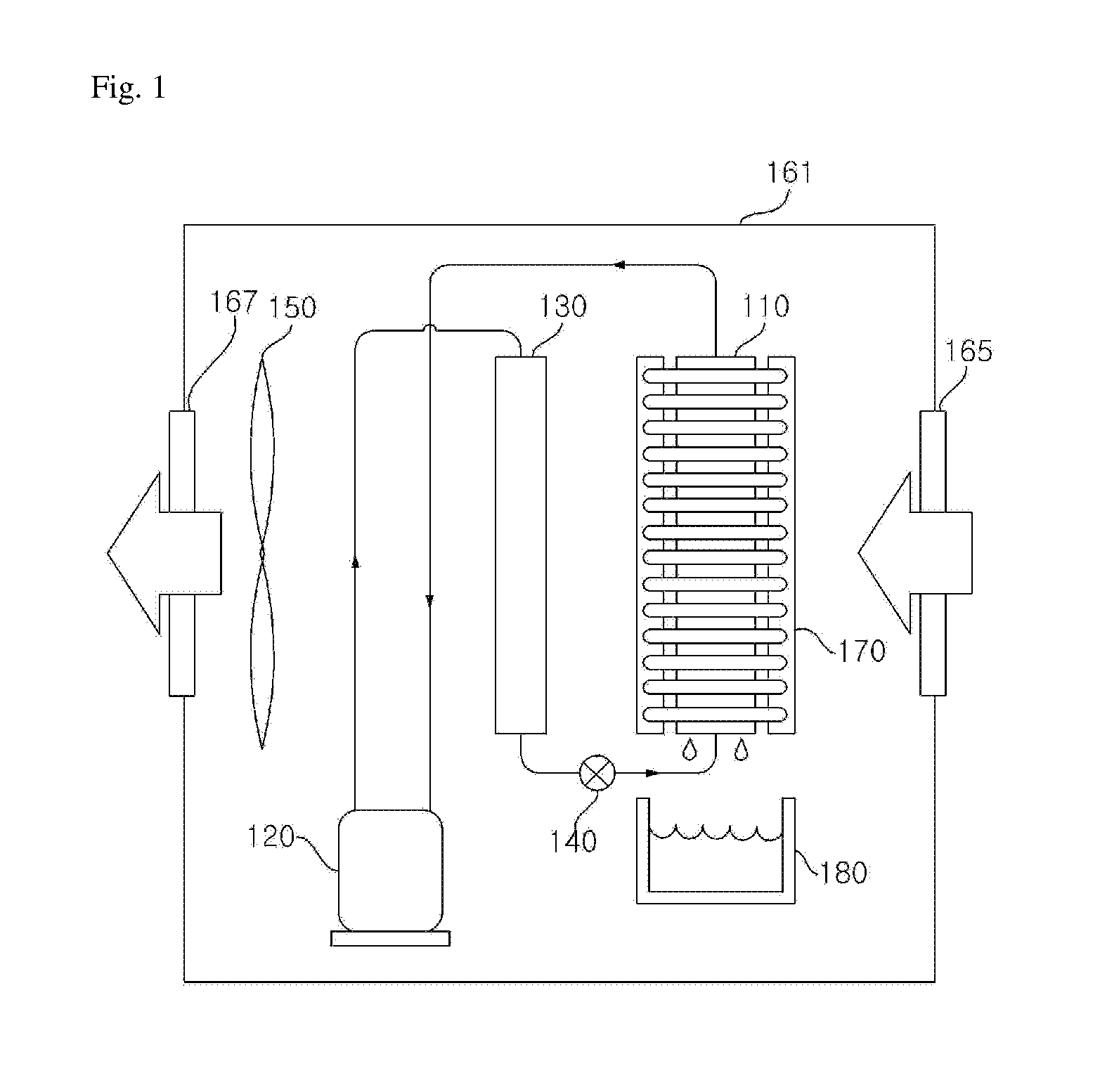
[0051] FIG. 1 is a structural view illustrating a dehumidifier according to an embodiment of the present invention.
[0052] The dehumidifier exemplified in FIG. 1 includes: a case 161 which forms or defines an exterior of the dehumidifier; a compressor 120 which compresses a refrigerant; a condenser 130 which condenses the refrigerant compressed by the compressor 120; an expander 140 which expands the refrigerant condensed by the condenser 130; an evaporator 110 which evaporates the refrigerant expanded by the expander 140; and a heat transfer module 170 which absorbs heat from air flowing into the evaporator 110 and transfers the heat to air discharged from the evaporator 110.
[0053] The case 161 forms an exterior of the dehumidifier. The case 161 includes, on one side, an inlet 165 formed therein through which air is introduced from the outside, and an outlet 167 formed therein through which the dehumidified air is discharged.
[0054] A blower fan 150, which circulates air, is disposed adjacent to the outlet 167 in the case 161. A water tank 180, which stores water condensed by the evaporator 110, is disposed below the evaporator 110 inside the case 161. The water tank 180 may be removably attached inside the case 161. The blower fan 150 blows air, which is dehumidified by the evaporator 110 and is heated by the condenser 130, so that it is discharged to the outside of the case 161 through the outlet 167. The evaporator 110 and the condenser 130 are disposed inside the case 161 and arranged along an air flow direction. The compressor 120 and the expander 140 are also disposed inside the case 161.
[0055] The compressor 120 is connected to the evaporator 110 and compresses a refrigerant which is evaporated by the evaporator 110. The compressor 120 is connected to the condenser 130, and the compressed refrigerant flows into the condenser 130.
[0056] The condenser 130 is connected to the compressor 120 and condenses the refrigerant, compressed by the compressor 120, by a heat exchange process with air. The condenser 130 heats air dehumidified by the evaporator 110. The air heated by the condenser 130 is discharged by the blower fan 150 through the outlet 167 to the outside of the case 161. The condenser 130 is connected to the expander 140, and the refrigerant, condensed by the condenser 130, flows into the expander 140.
[0057] The expander 140 is connected to the condenser 130 and expands the refrigerant condensed by the condenser 130. The expander 140 is connected to the evaporator 110, and the refrigerant, expanded by the expander 140, flows into the evaporator 110.
[0058] The evaporator 110 is connected to the expander 140 and evaporates the refrigerant, expanded by the expander 140, by a heat exchange process with air. The evaporator 110 functions to cool and dehumidify the air. The air, cooled and dehumidified by the evaporator 110, flows into the condenser 130. The evaporator 110 is connected to the compressor 120, and the refrigerant, evaporated by the evaporator 110, flows into the compressor 120. One portion of the heat transfer module 170 is disposed on a front surface of the evaporator 110, through which air is introduced, and the other portion of the heat transfer module 170 is disposed on a rear surface of the evaporator 110, through which air is discharged.
[0059] The heat transfer module 170 is disposed on the front surface (surface where air is introduced) of the evaporator 110, and on the rear surface (surface where air is discharged) of the evaporator 110. The heat transfer module 170 cools the air flowing into the evaporator 110, and heats the air discharged from the evaporator 110. The heat transfer module 170 is preferably configured as a heat pipe having an integrally formed fin, which will be described in detail with reference to FIG. 2 and the following figures.
[0060] FIG. 2 is a perspective view of a heat transfer module according to an embodiment of the present invention. FIG. 3 is a partial structural view of the heat transfer module illustrated in FIG. 2.
[0061] The exemplary heat transfer module 170 shown in FIG. 2 may include: a right module 170b which encloses a portion of the front surface, a right surface, and a portion of the rear surface of the evaporator 110; and a left module 170a which encloses a portion of the front surface, a left surface, and a portion of the rear surface of the evaporator 110; and a middle section module 190 which is disposed vertically at a middle portion between the front surface and the rear surface, and connects a left end of the right module 170b and a right end of the left module 170a.
[0062] In the embodiments of the present invention, the vertical direction and a longitudinal direction refer to the direction of gravity. A front direction refers to a direction in which air flows into the evaporator 110, and a rear direction refers to a direction in which air is discharged from the evaporator 110. That is, the front and rear direction refers to a direction, in which air flows, in a horizontal direction (transverse direction). The left and right direction refers to a direction, which is perpendicular to the front and rear direction with respect to the evaporator 110, in the horizontal direction (transverse direction).
[0063] In the embodiment, the evaporator 110, which has an approximately cuboid shape, may be disposed upright (not limited thereto), and may be disposed so that the front and the rear surfaces of the evaporator 110 are perpendicular to the air flow direction (front and rear direction) which is a horizontal direction.
[0064] The right module 170b may have a transverse section which is formed in an approximately staple shape (e.g., pronged shape), and may be disposed to enclose the right side of the evaporator 110. The right module 170b absorbs heat from air flowing to the right side of the evaporator 110 and is configure to transfer the heat to air discharged from the right side of the evaporator 110.
[0065] The left module 170a may have a transverse section which is formed in an approximately staple shape (e.g., pronged shape), and may be disposed to enclose the left side of the evaporator 110. The left module 170a absorbs heat from air flowing to the left side of the evaporator 110 and is configured to transfer heat to air discharged from the left side of the evaporator 110.
[0066] The left module 170a and the right module 170b may be heat pipe heat-exchangers having an integrally formed fin, and are desirably formed in the same shape.
[0067] Each of the right module 170b and the left module 170a may include: a plurality of side heat pipes 171 which are vertically spaced apart from each other; and a plurality of side cooling fins which are connected to the plurality of side heat pipes 171, and are horizontally spaced apart from each other.
[0068] Each of the plurality of side heat pipes 171 may have a fluid which is sealed therein. The plurality of side heat pipes 171 may rapidly transfer heat with a phase change in the fluid sealed therein. Each of the plurality of side heat pipes 171 may be formed in a U shape, and may be disposed horizontally.
[0069] Each of the plurality of side heat pipes 171 may include: two straight line parts 171b which are disposed to face each other; and a connection part 171a which connects the two straight line parts 171b. The longitudinal direction of the straight-line parts may be oriented in a horizontal direction. The straight-line parts may be disposed on the front surface and the rear surface of the evaporator 110.
[0070] Specifically, as shown in FIG. 2, two straight line parts 171b may be spaced apart from each other in the front and rear direction, and are extended in the left and right direction. One of the two straight line parts 171b may be disposed on the front side of the evaporator 110, and the other may be disposed on the rear side of the evaporator 110.
[0071] Each connection part 171a may be disposed on a lateral side of the evaporator 110. The connection part 171a may be disposed at least either one of the left side or the right side of the evaporator 110. The connection part 171a may connect ends of the straight-line parts 171b, and may have a curved or bent portion.
[0072] The straight-line parts 171b of each of the plurality of side heat pipes 171 may pass through the plurality of side cooling fins 173, to be connected to the plurality of side cooling fins 173. Ends of the straight-line parts 171b of each of the plurality of side heat pipes 171 may be connected to the middle section module 190 disposed between the left and right modules 170a and 170b.
[0073] Each of the plurality of side cooling fins 173 may be formed in a plate-like shape (not limited thereto). As shown in FIG. 2, the side cooling fin 170 is preferably formed such that it is vertically long and thin. Each of the plurality of side cooling fins 173 may have surfaces which are disposed horizontal to the air flow direction, such that air may flow through the plurality of side cooling fins 173.
[0074] Each of the plurality of side cooling fins 173 may be connected to the straight-line parts 171b. The straight-line parts 171b of the plurality of side heat pipes 171 pass through the plurality of side cooling fins 173, to be connected to the plurality of side cooling fins 173. Some of the plurality of side cooling fins 173 are disposed on the front surface of the evaporator 110, and other of the plurality of side cooling fans 173 are disposed on the rear surface of the evaporator 110. The plurality of side cooling fins 173, disposed on the front surface of the evaporator 110, absorb heat flowing into the evaporator 110, and are configured to transfer the heat to the plurality of side heat pipes 171 which are connected to the side cooling fins 173. The plurality of side cooling fins 173, disposed on the rear surface of the evaporator 110, are configured to transfer the heat of the plurality of side heat pipes 171, which are connected to the side cooling fins 173, to the air discharged from the evaporator 110.
[0075] The middle section module 190 may be connected to the left end of the right module 170b and the right end of the left module 170a, to connect the right module 170b with the left module 170a. The middle section module 190 may be formed in various shapes which allow connection of the right module 170b and the left module 170a. For example, as shown, the middle section module 190 may be formed in a plate-like shape which is vertically long and thin (not limited thereto). The middle section module 190 has surfaces which are disposed horizontal to the air flow direction, and are horizontally spaced apart from the plurality of side cooling fins 173. Preferably, the middle section module 190 has the same width and length as each of the side cooling fins 173. Further, preferably, the middle section module 190 is formed in the same shape as the side cooling fins 173 with the only difference being the width, so as not to disrupt the air flow.
[0076] In the embodiment disclosed herein, the middle section module 190 may include a plurality of connection holes 190h formed in a vertical direction thereof. As shown in FIG. 2, end portions of the plurality of side heat pipes 171 of the right module 170b and the left module 170a are alternately inserted into the plurality of connection holes 190h. In the embodiment, the plurality of side heat pipes 171 of the right module 170b and the plurality of side heat pipes 171 of the left module 170a are disposed alternately in a vertical direction. In the embodiment, two middle section modules 190 are provided, with one being disposed on the front surface of the evaporator 110 and the other being disposed on the rear surface of the evaporator 110.
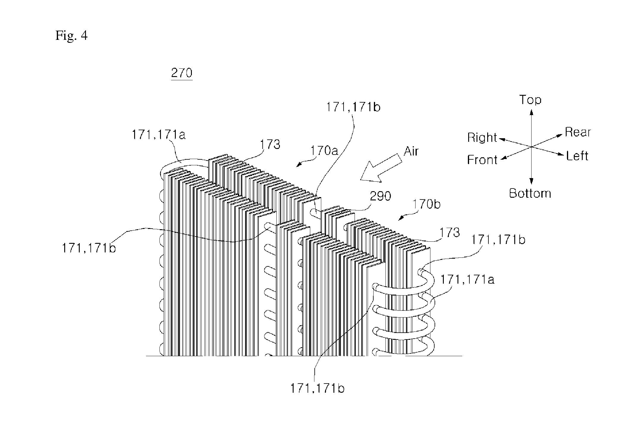
[0077] FIG. 4 is a perspective view of a heat transfer module according to another embodiment of the present invention. FIG. 5 is a partial structural view of the heat transfer module illustrated in FIG. 4.
[0078] The heat transfer module 270 disclosed in the exemplary embodiment of FIGS. 4 and 5 includes the right module 170b and the left module 170a, which are the same as the right module 170b and the left module 170a according to the embodiment shown in FIGS. 2 and 3 and described above, such that detailed description thereof will be omitted.
[0079] A middle section module 290 of the heat transfer module 270 may include: a plurality of sleeves 294 having both sides, into which end portions of the plurality of side heat pipes 171 of the right module 170b and the left module 170a are inserted; and a plurality of dummy fins 293 which are connected to the plurality of sleeves 294 and are arranged horizontally.
[0080] Each of the plurality of sleeves 294 may be formed in a tubular-like shape (not limited thereto). A longitudinal direction of each of the plurality of sleeves 294 may be oriented in a horizontal direction. The plurality of sleeves 294 may be vertically spaced apart from each other. The plurality of sleeves 294 may be connected, on the right side, to end portions of the plurality of side heat pipes 171 of the right module 170b; and are connected, on the left side, to end portions of the plurality of side heat pipes 171 of the left module 170a. The plurality of sleeves 294 may pass through the plurality of dummy fins 293, to be connected to the plurality of dummy fins 293. Some of the plurality of sleeves 294 may be vertically arranged at a center portion of the front surface of the evaporator 110, and other of the plurality of sleeves 294 may be vertically arranged at a center portion of the rear surface of the evaporator 110.
[0081] Each of the plurality of dummy fins 293 may be formed in a plate-like shape which is vertically long and thin (such as shown) (not limited thereto). Preferably, each of the plurality of dummy fins 293 is formed having the same shape as the side cooling fins 173. Each of the plurality of dummy fins 293 may have surfaces which are disposed horizontal to the air flow direction, such that the plurality of dummy fins 293 are horizontally spaced apart from each other along with the plurality of side cooling fins 173. A space between the plurality of dummy fins 293 may be equal, or substantially equal, to a space between the plurality of side cooling fins 173. The plurality of sleeves 294 may pass through the plurality of dummy fins 293 to be connected thereto. Some of the plurality of dummy fins 293 may be disposed on the front surface of the evaporator 110, and the other of the plurality of dummy fins 293 may be disposed on the rear surface of the evaporator 110.
[0082] FIG. 6 is a perspective view of a heat transfer module according to yet another embodiment of the present invention. FIG. 7 is a partial structural view of the heat transfer module illustrated in FIG. 6.
[0083] The exemplary heat transfer module 370 such as shown in FIGS. 6 and 7 may include the right module 170b and the left module 170a, which are the same as the right side module 170b and the left side module 170a according to the embodiments of the present invention described above, such that detailed description thereof will be omitted.
[0084] The heat transfer module 370 may include a middle section module 390, having a transverse section formed in an approximately in a square-like shape (not limited thereto), so as to enclose the front, rear, top, and bottom sides of a longitudinal center portion of the evaporator 110.
[0085] The middle section module 390 of the heat transfer module 370 may include a plurality of center heat pipes 391 that are horizontally arranged; a plurality of center cooling fins 393 that are connected to the plurality of center heat pipes 391 and are vertically spaced apart from each other; and a plurality of coupling frames 397 that are formed on all sides, including the top, bottom, left, and right sides, of the plurality of center cooling fins 393, and which are coupled to the right module 170b and the left module 170a.
[0086] Each of the plurality of center heat pipes 391 may have a fluid sealed therein. The plurality of center heat pipes 391 may rapidly transfer heat with a phase change in the fluid sealed therein. Each of the plurality of center heat pipes 391 may be formed in a rectangular-like shape with rounded edges or in a trapezoidal shape (not limited thereto), and be disposed upright. Each of the center heat pipes 391 has a long side which may be disposed vertically. Each of the center heat pipes 391 may have a long side which is disposed vertically at a center portion of the front surface and the rear surface of the evaporator 110. Each of the center heat pipes 391 may have a short side which is disposed at the top and the bottom of the evaporator 110. Each of the plurality of center heat pipes 391 may have a long side which passes through the plurality of center cooling fins 393 to be connected to the plurality of center cooling fins 393. The plurality of center heat pipes 391 may pass through a top surface and a bottom surface of each of the plurality of coupling frames 397, to be connected to the plurality of coupling frames 397.
[0087] Each of the plurality of center cooling fins 393 may be formed in a plate-like shape which is horizontally long and thin (such as shown, but not limited thereto). Each of the center cooling fins 393 may have surfaces which are disposed horizontal to the air flow direction, such that air may flow through the plurality of center cooling fins 393. A long side of each of the plurality of center heat pipes 391 may pass through the plurality of center cooling fins 393, to be connected thereto. Some of the plurality of center cooling fins 393 may be arranged vertically at a center portion of the front surface of the evaporator 110, and the other of the plurality of center cooling fins 393 may be arranged vertically at a center portion of the rear surface of the evaporator 110. The plurality of center cooling fins 393, disposed on the front surface of the evaporator 110, are configured to absorb heat of air flowing into the evaporator 110, and transfer the heat to the plurality of center heat pipes 391 which are connected to the plurality of center cooling fins 393. The plurality of center cooling fins 393, disposed on the rear surface of the evaporator 110, are configured to transfer the heat of the plurality of center heat pipes 391, which are connected to the plurality of center cooling fins 393, to air discharged from the evaporator 110.
[0088] Each of the plurality of coupling frames 397 may be formed in a square rim-like shape (not limited thereto), and disposed upright. Each of the plurality of coupling frames 397 may be disposed to be opened in an air flow direction (front and rear direction). Two coupling frames 397 may be provided, with one being disposed vertically at a center portion of the front surface of the evaporator 110, and the other of the coupling frames 397 may be disposed vertically at a center portion of the rear surface of the evaporator 110. A top surface and a bottom surface of each of the coupling frames 397 may be disposed at the top and the bottom of the plurality of center cooling fins 393 which are vertically arranged; and a left surface and a right surface of each of the coupling frames 397 may be disposed at the left side and the right side of the plurality of center cooling fins 393. The plurality of center heat pipes 391 may pass through the top surface and the bottom surface of each of the plurality of coupling frames 397, to be connected thereto.
[0089] A plurality of connection holes 397h may be formed vertically on the left surface and the right surface of each of the plurality of coupling frames 397. End portions of the plurality of side heat pipes 171 of the right module 170b may be inserted into the plurality of connection holes 397h formed on the right surface of the plurality of coupling frames 397. End portions of the plurality of side heat pipes 171 of the left module 170a may be inserted into the plurality of connection holes 397h formed on the left surface of the plurality of coupling frames 397.
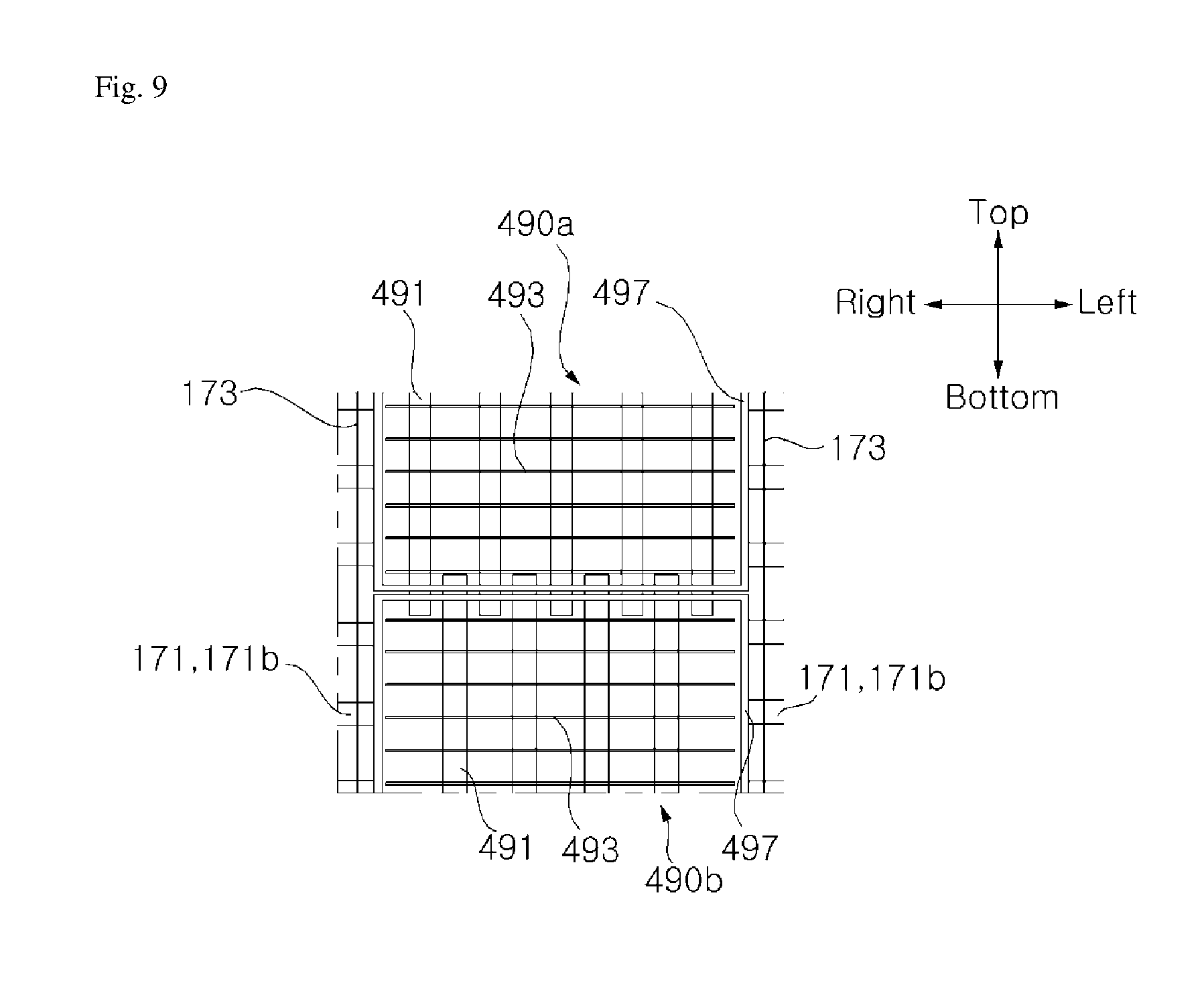
[0090] FIG. 8 is a perspective view of a heat transfer module according to still another embodiment of the present invention. FIG. 9 is a partial structural view of the heat transfer module illustrated in FIG. 8.
[0091] A heat transfer module 470 according to still another embodiment of the present invention may include the right module 170b and the left module 17a which are the same as the right module 170b and the left module 170a according to the embodiments of the present invention described above, such that detailed description thereof will be omitted.
[0092] The heat transfer module 470 according to the embodiment disclosed in FIGS. 8 and 9 may include a middle section module 490, which is formed by dividing the middle section module 390 illustrated in FIG. 6 into an upper portion and a lower portion, and includes an upper module 490a and a lower module 490b.
[0093] The upper module 490a includes a transverse section which may be formed in an approximately staple-like shape (not limited thereto), so as to enclose an upper portion of a horizontal center portion of the evaporator 110; and the lower module 490b has a transverse section which is formed in an approximately staple-like shape (not limited thereto), so as to enclose a lower portion of a horizontal center portion of the evaporator 110.
[0094] Each of the upper module 490a and the lower module 490b of the heat transfer module 470 may include: a plurality of center heat pipes 491 that are horizontally arranged; a plurality of center cooling fins 493 that are connected to the plurality of center heat pipes 491 and are vertically spaced apart from each other; and a plurality of coupling frames 497 that are disposed on all sides, including the top, bottom, left, and right sides, of the plurality of center cooling fins 493 and are connected to the right module 170b and the left module 170a.
[0095] For example, the plurality of center heat pipes 491 may be formed in a U shape (not limited thereto) and are vertically disposed. Each of the plurality of center heat pipes 491 includes a straight-line part, of which the longitudinal direction is vertically oriented, and is disposed on the front surface and the rear surface of the evaporator 110. Each of the plurality of center heat pipes 491 includes a connection part 171a which is disposed on the top surface or the bottom surface of the evaporator 110. In each of the plurality of center heat pipes 491, an end portion of the straight-line part 171b may be connected to the coupling frame 497.
[0096] Other descriptions of the plurality of center heat pipes 491, which are the same as the embodiments illustrated in FIG. 6, will be omitted to avoid repetition. Further, the plurality of center cooling fins 493 are the same as the embodiments illustrated in FIG. 6, such that detailed description thereof will be omitted to avoid repetition.
[0097] In the embodiment, four coupling frames 497 may be provided, with two being disposed vertically at a center portion of the front surface of the evaporator 110, and the other two being disposed vertically at a center portion of the rear surface of the evaporator 110. Each of the plurality of coupling frames 497 may have a left surface and a right surface, on which a plurality of first connection holes 497h1 are vertically formed. End portions of the plurality of side heat pipes 171 of the right module 170b may be inserted into the plurality of first connection holes 497h1 formed on the right surface of the plurality of coupling frames 497; and end portions of the plurality of side heat pipes 171 of the left module 170a may be inserted into the plurality of first connection holes 497h1 formed on the left surface of the plurality of coupling frames 497. Each of the plurality of coupling frames 497 may have a top surface and a bottom surface, on which a plurality of second connection holes 497h2 are formed in the left and right direction. End portions of the plurality of center heat pipes 491 of the upper module 490a may be inserted into the plurality of second connection holes 497h2 formed on the top surface of the plurality of coupling frames 497; and end portions of the plurality of center heat pipes 491 of the lower module 490b may be inserted into the plurality of second connection holes 497h2 formed on the bottom surface of the plurality of coupling frames 497.
[0098] FIG. 10 is a partial structural view of a heat transfer module according to still another embodiment of the present invention.
[0099] According to the embodiment shown in FIG. 10, each of a plurality of side cooling fins 573 may be formed as corrugated fins. Each of the plurality of side cooling fins 573 may be formed to be bent from a plurality of folding lines which are vertically formed.
[0100] FIG. 11 is a partial structural view of a heat transfer module according to still another embodiment of the present invention.
[0101] According to the embodiment shown in FIG. 11, each of a plurality of side cooling fins 673 may be formed as slit fins. Each of the plurality of side cooling fins 673 may have a surface which is partially cut and bent upward.
[0102] While the present disclosure has been shown and described with reference to the preferred embodiments thereof, it should be understood that the present disclosure is not limited to the specific embodiments, and various modifications and variations may be made by those skilled in the art without departing from the scope and spirit of the invention as defined by the appended claims, and the modified implementations should not be construed independently of the technical idea or prospect of the present disclosure.
* * * * *
D00000
D00001
D00002
D00003
D00004
D00005
D00006
D00007
D00008
D00009
D00010
D00011
XML
uspto.report is an independent third-party trademark research tool that is not affiliated, endorsed, or sponsored by the United States Patent and Trademark Office (USPTO) or any other governmental organization. The information provided by uspto.report is based on publicly available data at the time of writing and is intended for informational purposes only.
While we strive to provide accurate and up-to-date information, we do not guarantee the accuracy, completeness, reliability, or suitability of the information displayed on this site. The use of this site is at your own risk. Any reliance you place on such information is therefore strictly at your own risk.
All official trademark data, including owner information, should be verified by visiting the official USPTO website at www.uspto.gov. This site is not intended to replace professional legal advice and should not be used as a substitute for consulting with a legal professional who is knowledgeable about trademark law.