Membrane Heat And Mass Exchanger And Methods Of Manufacture
ARMATIS; Paul D. ; et al.
U.S. patent application number 16/203090 was filed with the patent office on 2019-05-30 for membrane heat and mass exchanger and methods of manufacture. This patent application is currently assigned to Oregon State University. The applicant listed for this patent is Oregon State University. Invention is credited to Paul D. ARMATIS, Brian M. FRONK, Steven KAWULA, Brian K. PAUL, Chuankai SONG, Hailei WANG.
| Application Number | 20190162429 16/203090 |
| Document ID | / |
| Family ID | 66632220 |
| Filed Date | 2019-05-30 |


| United States Patent Application | 20190162429 |
| Kind Code | A1 |
| ARMATIS; Paul D. ; et al. | May 30, 2019 |
MEMBRANE HEAT AND MASS EXCHANGER AND METHODS OF MANUFACTURE
Abstract
A heat and mass exchange (HMX) device comprising a plurality of membranes arranged in a stack. Adjacent membranes are separated from one another by an airflow channel Each membrane of the stack comprises an array of integrated support structures that extend into the airflow channel and to the second membrane. The support structures comprise an adhesive material that is bonded to each membrane. The support structures divide the airflow channels into subchannels.
| Inventors: | ARMATIS; Paul D.; (Corvallis, OR) ; PAUL; Brian K.; (Corvallis, OR) ; WANG; Hailei; (Corvallis, OR) ; FRONK; Brian M.; (Corvallis, OR) ; KAWULA; Steven; (Corvallis, OR) ; SONG; Chuankai; (Corvallis, OR) | ||||||||||
| Applicant: |
|
||||||||||
|---|---|---|---|---|---|---|---|---|---|---|---|
| Assignee: | Oregon State University Corvallis OR |
||||||||||
| Family ID: | 66632220 | ||||||||||
| Appl. No.: | 16/203090 | ||||||||||
| Filed: | November 28, 2018 |
Related U.S. Patent Documents
| Application Number | Filing Date | Patent Number | ||
|---|---|---|---|---|
| 62591400 | Nov 28, 2017 | |||
| Current U.S. Class: | 1/1 |
| Current CPC Class: | F28F 21/066 20130101; F28F 2275/025 20130101; F28D 21/0015 20130101; F24F 3/147 20130101; F28D 9/0062 20130101; F28F 2245/02 20130101 |
| International Class: | F24F 3/147 20060101 F24F003/147 |
Goverment Interests
GOVERNMENT SUPPORT
[0002] This invention was made with government support under Award No. DE-SC0006224, awarded by the United States Department of Energy. The government has certain rights in the invention.
Claims
1. A heat and mass exchange (HMX) device, comprising: a plurality of membranes arranged in a stack, wherein: adjacent ones of the plurality of membranes are separated by an airflow channel; the plurality of membranes comprise at least a first membrane and a second membrane over the first membrane; the first membrane comprises an array of support structures integrated on the first membrane; and the array of support structures each comprises an adhesive material that is bonded to the first membrane and extends to the second membrane.
2. The heat and mass exchange device of claim 1, wherein the ones of the array of support structures are bonded to the second membrane by adhesive bonds.
3. The heat and mass exchange device of claim 1, wherein: the ones of the plurality of membranes are elongated along a main axis and comprise a first header portion at a first end and a second header portion at a second end, the first header portion and the second header portion each have two non-parallel sides extending to a vertex, wherein the membrane has an elongated hexagonal shape; and the first header portion comprises a first array of fins oriented along a secondary axis that is non-parallel to the main axis, and the second header portion comprises a second array of fins oriented along the secondary axis.
4. The heat and mass exchange device of claim 1, wherein the ones of the plurality of membranes comprise silica-filled polyethylene, silica-filled polyvinyl chloride, silica-filled PEEK, or perfluorosulfonic acid, and has a thickness ranging between 20 and 30 microns.
5. The heat and mass exchange device of claim 1, wherein the adhesive material is any one of a silicone, an epoxy resin a urethane resin, a polyester resin, a silyl-terminated polyether resin, or an acrylic resin.
6. The heat and mass exchange device of claim 1, wherein the array of support structures is an array of strip fins, wherein ones of the array of strip fins are substantially parallel to one another and have a longitudinal span that extends along a length of the membrane, a transverse span that extends in a direction that extends along a width of the membrane, and a z-height that is approximately equal to the z-height of the first or the second airflow channels.
7. The heat and mass exchange device of claim 6, wherein the airflow channel is divided into two or more subchannels, wherein each one of the two or more subchannels is between a a pair of adjacent ones of the array of strip fins, wherein the pair of adjacent ones of the array of strip fins are sidewalls of each one of the two or more subchannels.
8. The heat and mass exchange device of claim 7, wherein the two more subchannels have a hydraulic diameter between 2 mm and 3 mm.
9. The heat and mass exchange device of claim 6, wherein ones of the array of strip fins have a ratio of the longitudinal span to the transverse span that is at least 100:1, and a ratio of the z-height to the transverse span that is between 1:1 and 2:1.
10. The heat and mass exchange device of claim 6, wherein the ones of the array of strip fins have a z-height of 4 mm or less.
11. The heat and mass exchange device of claim 6, wherein adjacent ones of the array of strip fins are separated from one another by a first distance that is one-tenth or less of the width of the membrane.
12. The heat and mass exchange device of claim 6, wherein the ones of the array of strip fins comprise one or more curved portions.
13. The heat and mass exchange device of claim 1, wherein the array of support structures is an array of pillars, wherein ones of the array of pillars each have a first transverse span extending along the membrane in the x- directions and a second transverse span extending along the membrane in the y-direction, and a z-height extending above the membrane, and wherein the z-height of the pillars is approximately the same as the z-height of the first or the second airflow channel.
14. The heat and mass exchange device of claim 13, wherein the first and second transverse spans are substantially equal, and the ones of the array of pillars each have a ratio of z-height to width that ranges from 1:1 and 2:1, and a ratio of length-to-width that ranges from 1:1 to 20:1.
15. The heat and mass exchange device of claim 13, wherein at least a portion of the ones of the array of pillars have a length extending along a first direction and a width extending along second direction that is orthogonal to the first direction, wherein the length is greater that the width.
16. An energy recovery ventilation (ERV) system comprising: a housing; a heat and mass exchange (HMX) device contained within the housing, the HMX device comprising: a plurality of membranes arranged in a stack, wherein: adjacent ones of the plurality of membranes are separated by an airflow channel; the plurality of membranes comprise at least a first membrane and a second membrane over the first membrane; the first membrane comprises an array of support structures integrated on the first membrane; and the array of support structures each comprises an adhesive material that is bonded to the first membrane and extends to the second membrane; and an air circulation system coupled to the HMX device such that air is circulated in a first direction through a first subarray of airflow channels, and in a second direction through a second subarray of airflow channels, wherein the first subarray is interleaved with the second subarray.
17. The ERV system of claim 16, wherein the array of support structures is an array of strip fins, wherein the array of strip fins has a z-height that is approximately equal to the z-height of the first or the second airflow channels; adjacent ones of the array of fins are sidewalls of a subchannel such that a first array of subchannels is within the first airflow channel and a second array of subchannels is within the second airflow channel; or the array of support structures is an array of pillars, wherein the array of pillars has a z-height that is approximately equal to the z-height of the first or the second airflow channels and the first direction is opposite the second direction such that air is circulated through the HMX in a counterflow configuration, or the first direction is orthogonal to the second direction such that the air is circulated through the HMX in a cross-flow configuration.
18. A method for making a heat and mass exchange device, comprising: receiving a heat and mass exchange (HMX) core stack, wherein the HMX core stack comprises a first membrane on the top of the core stack, the first membrane has a first surface over a second surface, the second surface bonded to a first layer of an adhesive material; depositing a second layer of the adhesive material in a support structure array pattern on the first surface to form a plurality of support structures on the first surface; and stacking a second membrane over the first membrane, wherein a third surface of the second membrane is opposite the first surface and is tacked onto the second layer of adhesive material, and the second membrane is at a first z-height over the first membrane.
19. The method of claim 18, wherein depositing the adhesive material comprises: dispensing the second layer of the adhesive material from a nozzle over the first surface, wherein the nozzle is translated relative to the first surface to dispense the adhesive material in a pattern; or dispensing the second layer of an adhesive material from the nozzle, wherein the wherein the nozzle is translated relative to the first surface in a first direction to deposit the adhesive material in a pattern; and dispensing a third layer of the adhesive material from the nozzle over the second layer of the adhesive, wherein the nozzle is translated relative to the first surface in a second direction opposite the first direction.
20. The method of claim 18, wherein stacking a second membrane over the first membrane comprises tacking the second membrane to the second layer of adhesive material and raising the second membrane to a second height over the first membrane and holding the position of the second membrane over the first membrane for a time period, wherein the adhesive material is stretched over the first membrane, and wherein a height of the second layer of adhesive material over the first membrane is increased and a height-to-width aspect ratio is 1:1 or greater.
Description
CROSS-REFERENCE TO PRIORITY DOCUMENTS
[0001] This U.S. Patent Application claims the benefit of priority under 35 U.S.C. 119(e) of U.S. Provisional Application No. 62/591,400, filed on Nov. 28, 2017.
BACKGROUND
[0003] A large amount of thermal energy is wasted when conditioned air in buildings is exhausted to the environment in order to meet ventilation requirements. Building ventilation systems may expend a good deal of energy to heat, cool, humidify or dehumidify a volume of fresh air taken in from the outside. Without any way to recover at least some of this energy, it is lost when the conditioned air is exhausted to the outside. Several technologies have been developed to recover some of the energy before the conditioned air is exhausted to the outside. Among these are Energy Recovery Ventilators (ERVs), which have recently been developed. ERVs exchange sensible heat and moisture between incoming fresh air and outgoing exhaust air. The exchange may be accomplished by countercurrent and cross-flow energy and mass exchange techniques through ERV cores comprising multiple membrane stacks. Market penetration of ERV devices has been hampered by high manufacturing costs and relatively low volumetric efficiency. A more advanced airflow architecture and method of manufacture of ERVs needs to be developed.
BRIEF DESCRIPTION OF THE DRAWINGS
[0004] The embodiments of the disclosure will be understood more fully from the detailed description given below and from the accompanying drawings of various embodiments of the disclosure, which, however, should not be taken to limit the disclosure to the specific embodiments, but are for explanation and understanding only.
[0005] FIG. 1 illustrates a plan view in the x-y plane of a heat and mass exchanger (HMX) membrane unit having integrated strip fin ribbing support structures, according to some embodiments of the disclosure.
[0006] FIG. 2 illustrates a plan view in the x-y plane of a HMX membrane unit having integrated elongated pillar support structures, according to some embodiments of the disclosure.
[0007] FIG. 3A illustrates a plan view in the x-y plane of a HMX membrane unit having integrated circular pillar support structures in a rectangular array, according to some embodiments of the disclosure.
[0008] FIG. 3B illustrates a plan view in the x-y plane of a HMX membrane unit having integrated circular pillar support structures in a hexagonal array, according to some embodiments of the disclosure.
[0009] FIG. 4 illustrates a plan view in the x-y plane of a HMX membrane unit having serpentine fin rib support structures, according to some embodiments of the disclosure.
[0010] FIG. 5 illustrates a partially exploded oblique view of a HMX core assembly comprising a stack of HMX membrane units, according to some embodiments of the disclosure.
[0011] FIG. 6 illustrates a flow chart summarizing an exemplary method for making a HMX core assembly, according to some embodiments of the disclosure.
[0012] FIGS. 7A-F illustrate a succession of key operations of an exemplary method to a HMX core assembly, according to some embodiments of the disclosure.
[0013] FIG. 8 illustrates a flow chart summarizing an alternative method for making a HMX core assembly, according to some embodiments of the disclosure.
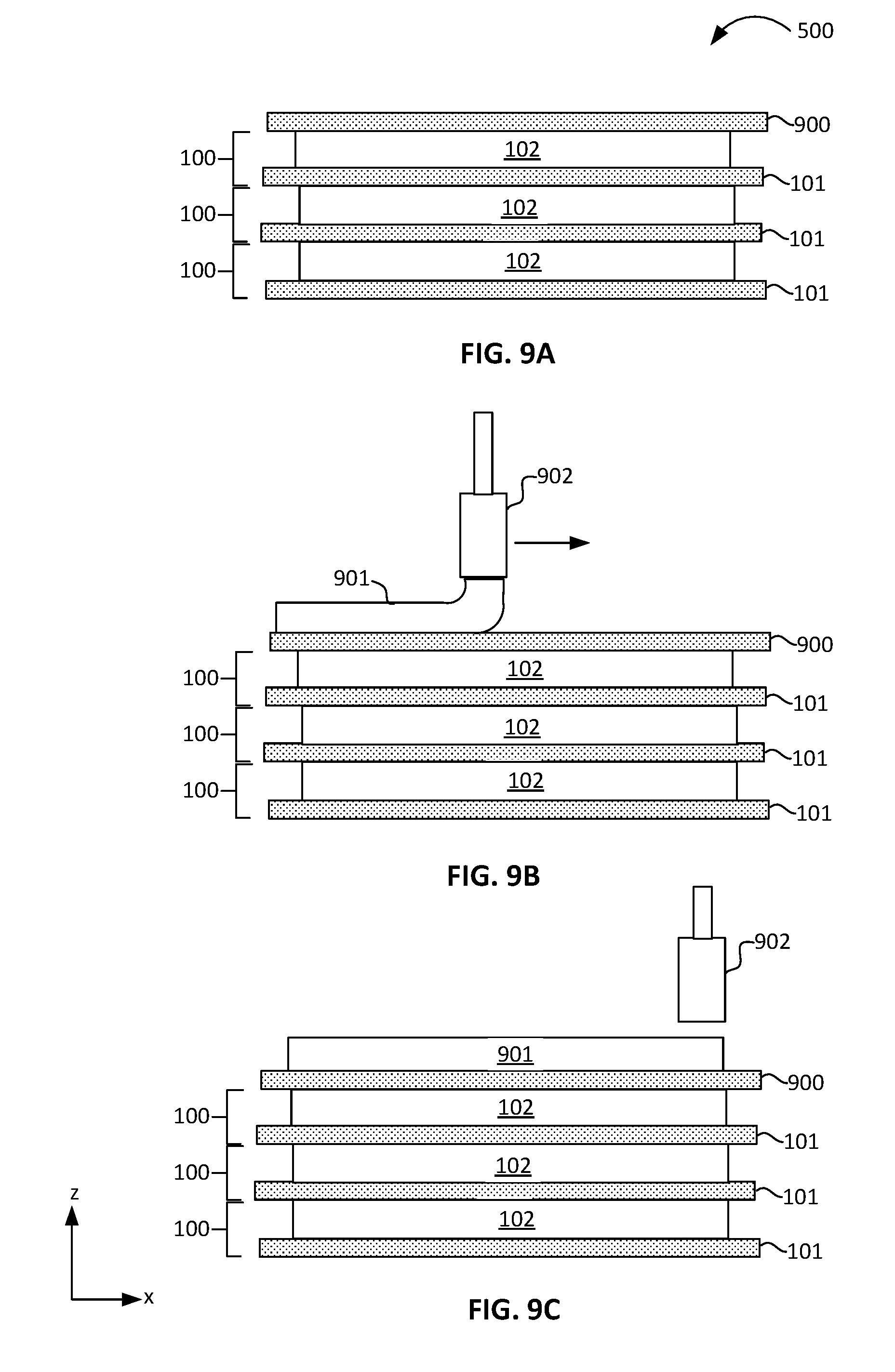
[0014] FIGS. 9A-9I illustrate a succession of key operations of an alternate exemplary method for making a HMX core assembly, according to some embodiments of the disclosure.
DETAILED DESCRIPTION
[0015] Described herein is a parallel membrane gas-to-gas heat and mass exchanger (HMX) device core for energy recovery ventilation (ERV) systems comprising multiple membranes having integrated support structures. The HMX core of an ERV system generally comprises a stack of parallel hydrophilic membranes, each separated by an airflow channel. The stack of airflow channels in the HMX may be arranged in a counter-flow or crossflow configuration.
[0016] Embodiments of the disclosed HMX membrane core comprises multiple HMX membranes having integrated support structures. The HMX membrane laminates exhibit low heat and mass transport resistance, in part due to their small thickness (e.g., a thickness less than 30 microns), and in part due to the hydrophilic membrane material exhibiting high selectivity to water transport. Support structures in the form of strip fins and/or pillars are incorporated onto the membrane material to enhance the rigidity of the membrane material that by itself is too thin to be self-supporting. Such membranes do not have sufficient rigidity as a stand-alone membrane to hold a specified shape without a scaffolding comprising a frame, ribbing or other types of support structure. The integrated structures permit the otherwise flaccid membranes to be self-supporting. When formed into a HMX core stack, an ensemble of the disclosed HMX membranes enable a high-efficiency and high-capacity heat and mass exchange in countercurrent, quasi-cross-flow (described below) or cross-flow configurations without the need for separate channeled spacers or frames. This allows for more compact form factors of the HMX cores.
[0017] To improve heat and mass transport in ERV systems, rigid membranes, which are generally thick (e.g., thicknesses greater than 50 microns) and have relatively high mass and heat transfer resistance, may be pleated or corrugated. Thin membranes (e.g., membranes having less than 30 microns in thickness) lack the rigidity to hold pleated folds or corrugations. One objective of pleating and corrugation of membranes is to increase membrane surface while maintaining a specified footprint. The increase in surface area helps to reduce mass and heat transfer resistance of the membrane, but the increase in surface area may be 100% or less, while the thickness of the membrane may be the principle contribution to transport resistance. Another objective of pleating and corrugation of the membrane is to increase convective transport of heat and mass from an airstream to the membrane by inducing some turbulence near the membrane surface. Thinner membranes may remain flat, without pleats or corrugations, and yet have much lower mass and heat transfer resistance in comparison to more rigid membranes without enhancement of convective transport within the airflow channel.
[0018] Rigid membranes that can form stand-alone structures on their own, such as pleated or corrugated membranes, may be substantially thicker or have fiber materials that tend to impede mass transfer. In some instances, pleated membranes comprise a fibrous paper or paper-like material that can be folded. Membranes having sufficient rigidity for maintaining a shape may also exhibit higher resistance to mass and heat transport.
[0019] In addition, reduction of the hydraulic diameter of the air channels (e.g., the space between membranes in a HMX core stack) has been incorporated into HMX designs to increase convective transfer from airstreams to the membranes. The reduction of the hydraulic diameter of airflow channels is generally done by decreasing the vertical spacing between membranes bounding the channels. Both methods have proven effective, but at the cost of high pressure drop across the HMX core stack. One operational objective of ERV installations in a building is a maximum allowable pressure drop (.DELTA.P) of 300 Pa (Pascals; e.g., approximately 0.05 psi). To meet this criterion, cores must have very low flow resistance within the airflow channels that are the spaces between membranes in an HMX core stack.
[0020] A criterion of the membrane is that it prevents mixing of airstreams on opposite sides of the membrane. Only diffusive transport processes are therefore permitted, and mass transport is generally limited to water vapor while excluding air (e.g., nitrogen and oxygen) and other organic and inorganic species. Water vapor carries latent heat that can be exploited for cooling and heating purposes. Sensible heat transfer is by conduction through the membrane.
[0021] To enable sufficient diffusive mass transport, the mass transport of water through the membrane must be highly efficient to allow sufficient mass in the form of water vapor to be exchanged across the membrane, to the exclusion of air and other gases. In particular, undesirable species in the air exhaust stream may be prevented from entering the outside air intake stream. Hydrophilic polymer membranes less than 30 microns in thickness are most efficient for this purpose. However, membranes having such small thicknesses are difficult to handle, and in general do not possess the requisite mechanical properties that make them amenable for employment in HMX core stacks as self-supporting structures. An important constraint is flexure or deflection in the membrane caused by pressure differentials in the airflow path between airflow channels on opposite sides of the membrane. Membrane deflection is especially prevalent in counter-flow configurations. Flexure must be limited to only a few percent of the vertical space in the airflow channel above the membrane, otherwise the hydraulic diameter of the flow channel is reduced and the flow resistance increases, increasing the pressure drop .DELTA.P. Thin membranes that are not self-supporting will deflect under pressure differentials across the membrane, and may increase .DELTA.P.
[0022] One objective is to reduce size and costs of ERV units. High-efficiency HMX membranes may enable a smaller footprint for some described embodiments of the disclosed HMX cores as compared to conventional HMX cores, permitting embodiments of the disclosed HMX core to fit within a compact space such as a building wall cavity as part of a building ERV system. The smaller footprint may be a smaller length-to-width aspect ratio of the HMX core, permitting the HMX core to be more easily integrated into the building envelope for new construction or retrofit purposes. As an example, some embodiments of the HMX core as disclosed may fit within cavities of walls of commercial buildings in North America, where wall thicknesses are generally 8-10 inches.
[0023] Membrane properties such as selectivity and low heat and mass transfer resistance are determinant for the development of compact, high capacity HMX cores. Many membrane types are available that meet these requirements, and are relatively inexpensive. Membrane cost may not be a limiting factor in achieving cost effectiveness goals of high capacity HMX cores. High-capacity membrane-based HMX cores that are currently on the market have associated high costs due to complex manufacturing and assembly procedures. In some cases, the assembly of membrane layer stacks as HMX cores requires a number of manual steps, including assembly of HMX core stacks with support frames that may be separately formed and may or may not be bonded to membrane laminates. Rigid membranes are generally employed for stack assembly to reduce or avoid handling difficulties often encountered with thin membranes. Consequently, these cores must be dimensionally large in comparison to the disclosed HMX cores to meet the same performance.
[0024] To address the problem of high manufacturing costs, a manufacturing method is disclosed herein that circumvents many of the manual manipulations of the membrane that are currently practiced to produce and assemble HMX membrane stack units or elements. The disclosed method embodiments comprise forming support structures that are directly integrated with the individual HMX membranes. The manufacturing process can be fully automated. Some embodiments of the disclosed manufacturing process comprise dispensing an adhesive material over one or both surfaces of a suitable membrane material. At a pre-process stage, the membrane material may be pre-cut to desired dimensions and shapes. Alternatively, the membrane material may be meted out as a continuous strip from a roller, then laser cut to produce individual membranes after structures have been formed.
[0025] In some embodiments, an adhesive material is dispensed from a nozzle to form beads of adhesive material as lines or pillars in a programmed pattern on the membrane surface. To accomplish this, the membrane may be fixed on a computer-controlled moving X-Y table, with the nozzle stationary. The table may also move in the z-direction so that the nozzle height above the membrane may be adjusted. Alternatively, the membrane may be stationary and the nozzle moves over the membrane to dispense the adhesive in a pre-programmed x-y pattern under computer control. The nozzle may also move in the z-direction to adjust the nozzle height over the membrane. In alternative embodiments, the adhesive material is sprayed or printed through a stencil. A roller applicator method may be used in this embodiment to print the adhesive onto the stencil, facilitating thickness adjustment of the uncured adhesive material.
[0026] The adhesive material may be dispensed as a paste or in a high-viscosity semi-liquid state, and is partially cured at this stage. To form support structures of a desired height above the membrane surface, more than a single layer of the adhesive may be applied. The height is important to create a flow channel with a minimal height for sufficient airflow without significant pressure drop (e.g., not exceeding 300 Pa). Attention is also paid to the lateral dimension of the structure, so as to minimize coverage of the active membrane surface. To minimize the lateral dimension of the structure, the adhesive is dispensed in layers. As dispensed, a bead of adhesive may have a circular cross-sectional height-to-lateral dimension ratio of 1:1, due to the bead holding its substantially circular cross-sectional shape. As an example, the bead is approximately 1 mm in cross-sectional diameter. During curing, the first layer of adhesive material may collapse by some flow, producing a structure having an aspect ratio of less than 1:1, often as low as 0.6:1 or lower. With such low aspect ratios, multiple layers of adhesive may need to be dispensed over each other to achieve a target structure height. As a greater amount of adhesive would need to be dispensed, incurring longer and more expensive process times and/or loss of active membrane surface.
[0027] To circumvent this problem, maintenance of larger height-to-lateral dimension (e.g., width or diameter) aspect ratio adhesive beads may be achieved by dispensing a first bead layer of a suitable adhesive, then allowing some adhesive bond formation to take place with the membrane, but not curing the adhesive. In this way, the adhesive structure (e.g., bead) remains tacky, but has enough body so as to maintain its initial shape, having a height-to-lateral dimension aspect ratio of 1:1 (or more). The dispensing nozzle may be displaced vertically (in the z-direction) relative to the membrane and a second layer of the adhesive may be dispensed directly over the first layer. In some embodiments, the second bead is dispensed in the opposite direction relative to the first bead. At this point, the first layer may be hardened enough to support the second layer without losing its initial shape and height-to-width aspect ratio, yet having enough tack for adhesive bonds with a second layer.
[0028] According to some embodiments, the second layer as dispensed may not be as thick as the first layer, allowing a total height-to-width aspect ratio ranging from 1:1 to 2:1. In this manner, a target height may be achieved with the minimal number of dispensed layers of adhesive, saving manufacturing time and costs. At the same time, the coverage of active membrane surface is minimal. The second layer may be bonded with a second adjacent membrane, sealing the intermembrane airflow channel The membrane-integrated support structures formed according to the described embodiments disclosed herein provide mechanical support for the compliant membranes, form flow paths within the airflow channels, and seal the airflow channels to prevent leakage of air in and out of the airflow channels and produce rigid HMX core stacks that do not require external framework or other support mechanisms.
[0029] In an alternative method, a HMX core stack is received in process, where the HMX core stack is partially complete. The HMX core stack has a top membrane that has no adhesive material on the top surface of the membrane. A layer of adhesive material is deposited in a pattern of beads on the surface of the top membrane. The pattern of beads is an array of nascent support structures that may be dispensed from a nozzle or deposited by through a stencil. A blank membrane that is mounted on a movable platen is tacked down over the adhesive layer, which is firm but tacky, forming adhesive bonds with the blank membrane. The blank membrane is raised upward, pulling the adhesive layer upward with it due to tensile forces, stretching the material vertically. The height of the adhesive layer over the top membrane is increased in this way, while the width of the beads decrease as material is pulled upward. The height-to-width aspect ratio may be increased in this manner to values of 1:1 or greater.
[0030] Here, the term "integrated" generally refers to a structure or multiple structures formed directly on a substrate and bonded to it. As part of this definition, the bonding of the structure(s) to the substrate is generally part of the formation process. The formation process comprises depositing an adhesive material on a membrane surface, where the membrane is the substrate.
[0031] Here, the term "adhesive bond" may have several definitions. In one definition, an adhesive bond may be defined as chemical bonding between the reactive molecular groups at the interface between the structure(s) and the substrate. Reactive groups in the uncured adhesive material that is deposited on the membrane to form the structures by internal cross-linking, may also form chemical linkages to the substrate during the curing process, chemically bonding the structure(s) to the substrate. In another definition, an adhesive bond may be defined as a physical bond, such as formed by van der Waals forces established between the structure(s) and the substrate. In a further definition, an adhesive bond may be defined as a mechanical bond formed by infiltration of the material of the structure(s) into microscopic pores or between microscopic irregularities at the interface between the structure(s) and the substrate. According to the embodiments disclosed herein, the integrated support structures described above are directly formed on a membrane material and bonded to it by any of the adhesion mechanisms just described. Accordingly, the integrated structures comprise an adhesive material that is cured to form solid or semi-solid structures that are directly bonded to the membrane substrate without an intermediary of a second adhesive substance at the interface of the integrated support structures and the membrane substrate.
[0032] Here, the term "adhesive" generally means a substance that is expressly employed for the purposes of forming chemical bond linkages or physical bonds (e.g., van der Waals bonds, hydrogen bonds) between the substance and a substrate, for binding objects together. The substance is formulated and marketed, if sold commercially, as a glue, a sealant, an adhesive or a cement, according to standard definitions. The substance is generally obtained in a precursor, a pre-bond state that may be characterized as "resinous", which may be further characterized as a viscous liquid. Some examples of an adhesive are so-called hot glues, where the adhesive is a thermoplastic resin procured as a solid material a room temperature. The thermoplastic resin is then melted and applied in a molten state to one or more substrates. In the molten state, the "hot glue" material is tacky and adheres to many types of substances. Chemical (e.g., reactive) or physical (e.g., van der Waals) bonds are formed between the substrate(s) and the hot adhesive. The hot adhesive hardens upon cooling, and bonds to the substrate(s). The hot adhesive may be a thermoplastic material. This type of adhesive may be particularly suitable for adhering to non-polar surfaces (e.g., having low surface energy) of many plastics by van der Waal forces, as the resin itself may be non-polar thermoset plastic.
[0033] An adhesive may form bonds to substrates by chemical reaction, and polymerize internally by similar reactions between reactive groups on nearby polymer chains, forming a hardened or cured material that is chemically bonded to the substrate. By chemical bonding, it is understood that chemical linkages are established between the polymer backbone of polymers in the adhesive and reactive groups at the substrate surface. For example, ester linkages may be formed between surface hydroxyl groups and carboxylic groups on the polymer chains of the adhesive by a condensation reaction. For silicone-based adhesives, bonds may also be formed between silanol groups and available surface-bound hydroxyl groups on the substrate. Ether linkages, y bonds may be formed by the Such adhesives comprise reactive molecular precursors that are oligomeric and polymeric chains having pendant reactive groups that remain stable in the absence of moisture, air (oxygen) elevated temperatures and/or light (e.g., ultraviolet light). A solvent may be present as well in the material to reduce viscosity and exclude moisture and air. Catalysts may also be included in the formulation that promote cross-linking or polymerization of the precursor molecules when the in the pendant adhesive is exposed to moisture, air, heat and/or light. In the pre-cure state, the adhesive is often sticky or tacky, meaning it forms bonds with solid substrates
[0034] When curing, the precursor molecules may undergo reactions that grow the polymer chains and/or crosslink them, causing the liquid adhesive precursor to "harden" into a highly viscous glassy substance, or one that at least partially crystallizes into crystalline domains. The adhesive may harden to form a thermoset plastic, which cannot melt into a liquid once set. Other adhesives may contain a non-chemically reactive polymeric materials dissolved in a solvent, such as emulsion and polymer dispersion adhesives, where curing involves evaporation of the solvent (e.g., drying), causing the polymeric molecules to lock together in the absence of the solvent, forming an amorphous (glassy) solid polymer, a polycrystalline solid or a solid comprising combination of the two states. In other examples, the polymeric material comprises an elastomer, and forms an elastic solid when dry. Some adhesives, such as epoxies are resins that are mixed with a hardener, which cross-links the resin during the curing process to form a thermoset solid plastic. The curing takes place at room temperature, but may be accelerated at elevated temperatures. Epoxies comprise polymer chains that are replete with polar groups such as hydroxyls, ether linkages, secondary and tertiary amino and imino groups, which give the adhesive power, forming hydrogen bonds or van der Waals bonds with a substrate.
[0035] As a result of the curing process, the adhesive "hardens", meaning that the adhesive solidifies or becomes a semi-solid that is chemically or physically bonded to the substrate(s). The solidified adhesive may remain amorphous, being glass-like, or form crystalline domains, having properties of polycrystalline solids. Some adhesives, such as epoxies, harden into a thermoset plastic material. Some adhesives, such as silicones and so-called rubber cement, comprise elastomeric molecules and retain elastic, rubber-like properties. The precursor molecules may comprise relatively low molecular-weight polymer chains that have pendant bonds, such as, but not limited to, epoxide groups, carboxylic acid group, amino groups, imino groups, sulfhydryl groups, hydroxyl groups, acrylate groups and undergo further polymerization and cross-linking to other polymer chains. The adhesive power of the material may be due to similar reactions with surface groups on a substrate, or by formation of strong van der Waals forces or hydrogen bonds at the interface between the adhesive and the substrate.
[0036] Adhesives are characterized as having an "open" time and a cure time. The open time is the time the adhesive remains pliable in the pre-cured state. The adhesive may be in a liquid state having a sufficient viscosity to retain a shape when extruded from a nozzle and resist flowing during the open time. Some adhesives may be molded or otherwise shaped while in the open state.
[0037] For purposes of description of the disclosed embodiments and the views shown in the figures, the vertical orientation is in the z-direction and it is understood that recitations of "top", "bottom", "above" and "below" refer to relative positions in the z-dimension with the usual meaning. However, it is understood that embodiments are not necessarily limited to the orientations or configurations illustrated in the figure.
[0038] The terms "substantially," "close," "approximately," "near," and "about," generally refer to being within +/-10% of a target value (unless specifically specified). Unless otherwise specified the use of the ordinal adjectives "first," "second," and "third," etc., to describe a common object, merely indicate that different instances of like objects are being referred to, and are not intended to imply that the objects so described must be in a given sequence, either temporally, spatially, in ranking or in any other manner.
[0039] For the purposes of the present disclosure, phrases "A and/or B" and "A or B" mean (A), (B), or (A and B). For the purposes of the present disclosure, the phrase "A, B, and/or C" means (A), (B), (C), (A and B), (A and C), (B and C), or (A, B and C).
[0040] Views labeled "cross-sectional", "profile", "plan", and "oblique" correspond to orthogonal planes within a cartesian coordinate system. Thus, cross-sectional and profile views are taken in the x-z plane, plan views are taken in the x-y plane, and isometric views are taken in a 3-dimensional cartesian coordinate system (x-y-z). Where appropriate, drawings are labeled with axes to indicate the orientation of the figure.
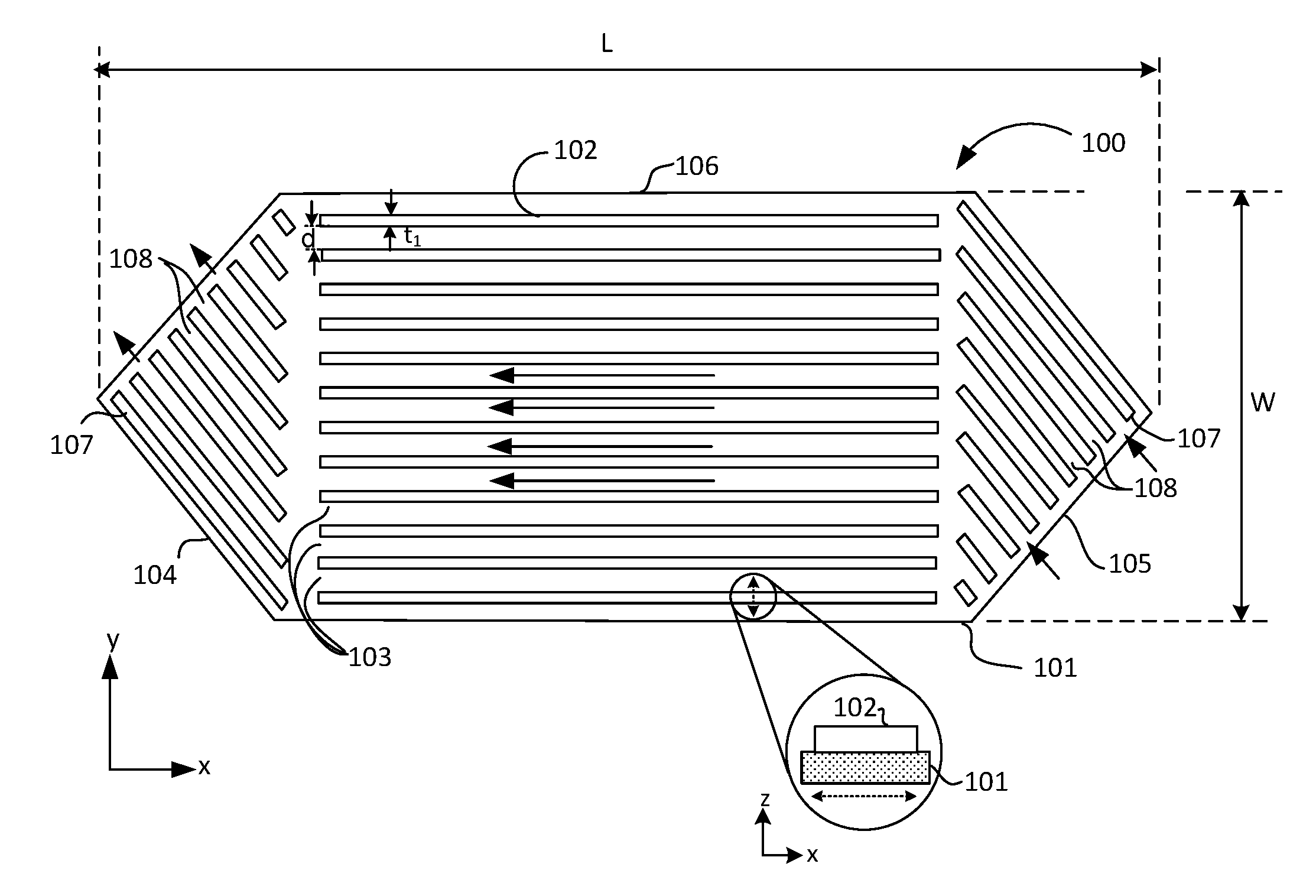
[0041] FIG. 1 illustrates a plan view in the x-y plane of HMX membrane unit 100 having integrated fin ribbing support structures 102, according to some embodiments of the disclosure.
[0042] HMX membrane unit 100 comprises membrane 101 and an array of multiple integrated strip fins 102 extending across the face of membrane 101 in the x-direction of the figure. In some embodiments, membrane 101 has a thickness ranging between 20 microns and 30 microns. In some embodiments, strip fins 102 have a height (not shown) ranging between 1 mm and 4 mm, and a thickness t.sub.1 ranging between 1 mm and 2 mm Strip fins 102 provide sidewalls for subchannels 103 to direct airflow when HMX membrane unit 100 is employed in a HMX core stack. The orientation of strip fins 102 and associated subchannels 103 defines the direction of length L of HMX membrane unit 100 extending in the x-direction of the figure, where the width W of HMX membrane unit 100 extends in the y-direction of the figure. In some embodiments, the length-to-width (L/W) aspect ratio of HMX membrane unit 100 is 2:1 or greater. In some embodiments, HMX membrane unit 100 has an overall length L ranging between 500 mm and 1000 mm. In some embodiments, the overall width W ranges between 150 mm and 200 mm In some embodiments, subchannels 103 have a width d ranging between 3 mm and 7 mm. In general, width d is one tenth or less of the width of HMX membrane unit 100, allowing an array comprising 10 or more subchannels 103 to fit in an HMX membrane unit 100. The cross-sectional area ranges between 3 mm.sup.2 and 20 mm.sup.2. In some embodiments, the hydraulic diameter d.sub.h of subchannels 103, where d.sub.h is defined as four times the cross-sectional area A divided by the cross-sectional perimeter P (d.sub.h=4A/P) ranges between approximately 1.5 mm and 4.0 mm In some embodiments, HMX membrane unit comprises between 30 to 70 subchannels 103.
[0043] According to some embodiments, HMX membrane unit 100 is hexagonal in shape, as shown in FIG. 1. Triangular-shaped headers 104 and 105 extend from the rectangular main body 106 of HMX membrane unit 100 at the left and right ends, respectively. Headers 104 and 105 comprise strip fins 107 that are oriented at an angle relative to the strip fins 102 in main body 106. In the illustrated embodiment, strip fins 107 are oriented at approximately a 45.degree. angle to strip fins 102. It will be understood that other suitable relative orientations may be employed for strip fins 107. In some embodiments, strip fins 107 have the same cross-sectional dimensions of strip fins 102. Headers 104 and 105 are interchangeably airflow introduction and exhaust portions of HMX membrane unit 100.
[0044] The triangular shape of headers 104 and 105 permits stacking of HMX membrane units with alternate header orientations, so that quasi-cross flow HMX core stack configurations (described below) may be obtained, where intake and exhaust air streams may both be couple to the HMX core stack on the same end, as described below. Strip fins 107 serve to direct air flow to or away from main body 106 though associated subchannels 108, while permitting some heat and mass exchange to take place within headers 104 and 105 before or after the bulk of the heat and mass transport occurs in main body 106. This is explained below and shown for quasi-cross flow HMX core stack configurations.
[0045] In alternate embodiments, HMX membrane unit 100 is rectangular in shape, as described below. The rectangular shape is commonly employed in cross-flow HMX core stack configurations.
[0046] Membrane 101 comprises a hydrophilic membrane material including, but not limited to, silica-filled polyethylene, silica-filled polyvinyl chloride, silica-filled polyethylene ethyl ketone (PEEK), paper and cellulosic materials, or perfluorosulfonic acid. In some embodiments, membrane 101 exhibits a diffusivity D.sub.m for water ranging between 2.times.10.sup.7 m.sup.2s.sup.-1 and 4.times.10.sup.7 m.sup.2s.sup.-1 at room temperature. In some embodiments, membrane 101 has a heat condutivity ranging between 0.05 and 0.10 W/mK. Strip fins 102 and 107 are formed from an adhesive material by process embodiments described below.
[0047] In some embodiments, strip fins 102 and 107 comprise a substantially polymerized adhesive material homogeneously distributed within the interior of the structures and at the surface, including, but not limited to, silicone resins, epoxy resins, polyimide resins, urethane resins, cyanoacrylate resins, acrylate resins. Any suitable adhesive material having a suitable cure time at room temperature and cure temperature below the glass transition temperature of membrane 101 may be employed. Suitable adhesive materials may be a paste or a gel-like material that exhibits a high viscosity as a freshly deposited bead of adhesive (e.g., a bead or line of the adhesive extruded from a nozzle) on a substrate. In some embodiments, the adhesive material has a viscosity or a degree of internal bonding such that the bead does not flow under its own weight (e.g., does not slump) and retains its extruded form until cured.
[0048] According to some embodiments, strip fins 102 and 107 are directly integrated with membrane 101 by formation of the structures from adhesive material deposited and cured on membrane 101 as the substrate. The method of manufactured of HMX membrane unit 100 described below gives details of the integration process. Structurally, the transition from membrane material to bulk material composition of strip fins 102 and 107 at the membrane interface is substantially sharp (e.g., no intervening layer of a material is present at the interface). This is shown by the inset of FIG. 1, where a small section of HMX membrane unit 100 is taken along the y-axis in an x-z plane indicted by the dashed line cutting across the lower-most strip fin 102 within the small circle. The section is shown magnified in the inset, where the x-z coordinate axes indicate the section is in the x-z plane. The inset shows that strip fin 102 is interfaced directly with and bonded to membrane 101 by adhesive bonds as described above, with no intervening layer of material between strip fin 102 and membrane 101.
[0049] The adhesive bonds may be chemical bonds formed between strip fin 102 and membrane 101 by native reactive groups of the adhesive material comprised by strip fin 102 and reactive groups native to the membrane material comprised by membrane 101 (e.g., surface hydroxyl groups, amino groups, oxo groups, carboxylic acid groups, etc.). In some embodiments, the adhesive bonds are physical bonds such as van der Waals interactions, as described above. This type of bond may be formed by electrostatic interaction between polar groups on polymer chains native to the adhesive material comprised by strip fins 102 electrostatically and polar groups on polymer chains native to the membrane material comprised by membrane 101.
[0050] In some embodiments, physical bonds may be formed by infiltration of the adhesive material comprised by strip fins 102 into pores in membrane 101.
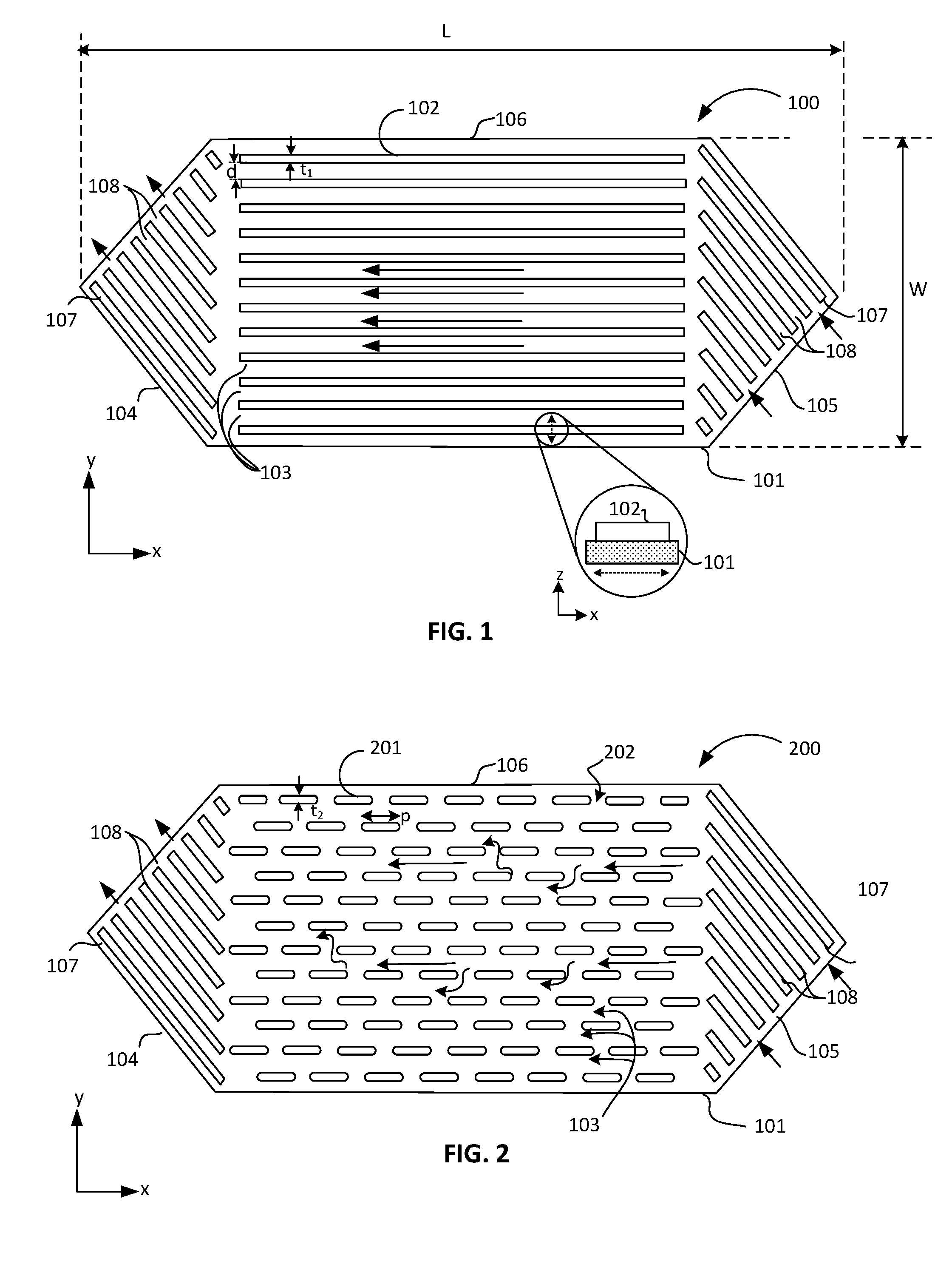
[0051] FIG. 2 illustrates a plan view in the x-y plane of HMX membrane unit 200 having integrated elongated pillar support structures 201, according to some embodiments of the disclosure.
[0052] HMX membrane unit 200 comprises elongated pillars 201 integrated onto membrane 101. The overall description of HMX membrane unit 100 is generally applicable to HMX membrane unit 200, with some exceptions. In some embodiments, elongated pillars 201 have a similar height-to-width aspect ratio to that of strip fins 102 shown in FIG. 1, ranging between 1:1 and 2:1. Elongated pillars 201 have a length p extending in the x-direction in the figure, and a width t.sub.2 extending in the y-direction of the figure. In some embodiments, width t.sub.2 of elongated pillars 201 is the same as for the width t.sub.1 for strip fins 101. In some embodiments, elongated pillars 201 have length-to-width ratio (p/t.sub.1) ranging between 2:1 and 20:1. Elongated pillars 201 are separated from each other along the x-direction by gaps 202. In some embodiments, the ratio of the length of elongated pillars 201 to the length of gaps 202 ranges from approximately 1:1 to 10:1. While the elongated pillar structure provides complex flow paths for airflow within HMX membrane unit 200 with no well-defined subchannels (e.g., no delineated flow channels as are subchannels 103 in FIG. 1). Air may flow along subchannels (not specified) longitudinally along elongated pillars 201, or transversely between longitudinal flow paths. In some embodiments, the height of elongated pillars 201 (not shown) is between 1 mm and 4 mm. The hydraulic diameter of HMX membrane unit 200 is substantially the same as the hydraulic diameter for HMX membrane unit 100, ranging between approximately 1.5 and 4 mm.
[0053] HMX membrane unit 200 comprises header portions 104 and 105 extending from main body 106 of membrane 101, comprising strip fins 107 integrated onto the membrane material forming headers 104 and 105, providing sidewalls for subchannels 108. In some embodiments, the general description of headers 104 and 105 given for HMX membrane unit 100 is applicable to HMX membrane unit 200. Headers 104 and 105 perform the same or a similar function as was described above for HMX membrane unit 100. Principally, headers 104 and 105 may provide conduits in the form of subchannels 108 for introducing intake air and removing exhaust air from main body 106 at opposite ends of membrane 101.
[0054] Elongated pillars 201 are integrated directly on membrane 101, as described above for strip fins 102 in HMX membrane unit 100.
[0055] FIG. 3A illustrates a plan view in the x-y plane of HMX membrane unit 300a having integrated circular pillar support structures 301 in a rectangular array, according to some embodiments of the disclosure.
[0056] HMX membrane unit 300a comprises circular pillars 301 configured in a rectangular or square array, integrated onto membrane 101. Spacing between circular pillars 301 extends in the x-dimension and the y-dimension. In some embodiments, x-spacing p.sub.2 and y-spacing p.sub.3 range between 2 mm and 4 mm. In some embodiments, p.sub.2 is substantially equivalent to p.sub.3, yielding a square array. In alternative embodiments, p.sub.2 and p.sub.3 are not equal, yielding a rectangular array. In some embodiments, circular pillars 301 have a height (not shown) ranging between 1 mm and 4 mm. In some embodiments, circular pillars 301 have a diameter ranging between 0.5 mm and 2 mm.
[0057] Headers 104 and 105 introduce and remove airstreams from main body 106 of membrane 101. Strip fins 107 are integrated onto the membrane base of headers 104 and 105, providing airflow subchannels 108 between strip fins 107, which are sidewalls for subchannels 108. The flow paths for introduced air within the main airflow channel in which circular pillars 301 are distributed are random, as indicated by the arrows in the gaps between circular pillars 301. Primary flow vectors are in the x- and y-directions, entering flow orifices between circular pillars 301 having widths of p.sub.2 or p.sub.3, and height h. A hydraulic diameter may be defined as {4.times.h.times.p.sub.2(3)}/{(2.times.p.sub.2(3))+2h}, where h is the pillar height. p.sub.2 and p.sub.3 are interchangeable, as indicated by the parentheses in the subscript of p. In some embodiments, the hydraulic diameter ranges between approximately 1.5 and 4.
[0058] The general description of HMX membrane unit 100 is applicable to HMX membrane unit 300a. Headers 104 and 105 extend from both ends of membrane 101, and comprise integrated strip fins 107, dividing subchannels 108. The triangular shape of headers 104 and 105 serves to provide separate flow paths for intake air and exhaust air on the same side of a HMX core (shown in FIG. 5).
[0059] When multiple HMX membrane units 300a are assembled in stack, circular pillars 301 extend from membrane 101 to a second membrane (not shown). In some embodiments, circular pillars are bonded to the second membrane, forming a seal. In some embodiments, the height of circular pillars 301 is the height of the main airflow channel between membranes. Multiple HMX membrane units 300a may be bonded together, forming a rigid HMX and sturdy core stack comprising high-performance membranes (e.g., membrane 101). Main airflow channels are formed between stacked HMX membrane units 300a, having circular pillar (e.g., circular pillars 301) as inner integrated support structures.
[0060] FIG. 3B illustrates a plan view in the x-y plane of HMX membrane unit 300b having integrated circular pillar support structures 301 in a hexagonal array, according to some embodiments of the disclosure.
[0061] HMX membrane unit 300b comprises circular pillars 301 configured in a hexagonal array, integrated onto membrane 101. Spacing between circular pillars 301 extends in the x-dimension and in a diagonal direction, indicated by the dashed lines. In some embodiments, x-spacing p.sub.4 and vertical (y) spacing p.sub.5 range between 2 mm and 4 mm. In some embodiments, circular pillars 301 have a height (not shown) ranging between 1 mm and 4 mm. In some embodiments, circular pillars 301 have a diameter ranging between 0.5 mm and 2 mm.
[0062] Similar to the description for HMX membrane unit 300b, headers 104 and 105 introduce and remove airstreams from main body 106 of membrane 101. Strip fins 107 are integrated onto the membrane base of headers 104 and 105, providing airflow subchannels 108 between strip fins 107, which are sidewalls for subchannels 108. The flow paths for introduced air within the main airflow channel in which circular pillars 301 are distributed are random, as indicated by the arrows in the gaps between circular pillars 301. The arrows indicate various flow paths that the air streams can take. Primary flow vectors, indicated by the arrows entering header 105 and the bent arrows drawn in main body 106, are in the x- and diagonal directions, entering flow orifices between circular pillars 301 having widths of p.sub.4 or distance .alpha.=p.sub.5/cos .theta., where .theta. is the angle of the diagonal, and height h. A hydraulic diameter may be defined for any of the flow paths as the distances between circular pillars 301 and the height h of circular pillars 301 may be substantially constant. The flow path hydraulic diameter d.sub.h may be defined as {4.times.h.times.p.sub.4(.alpha.)}/{(2.times.p.sub.4(.alpha.))+2h}, where h is the pillar height. p.sub.4 and .alpha. are interchangeable, as indicated by the parentheses in the subscript of p. In some embodiments, the hydraulic diameter of the flow ranges between approximately 1.5 and 4, depending on the values for p.sub.4, .alpha. and h.
[0063] The flow paths may be substantially random, as shown by the arrows within main body 106. Airstreams entering from header 105 encounter circular pillars 301 where the airstreams may be deflected laterally, then begin to split into multiple paths. This is indicated by the arrows drawn in the main body 106. The multiple paths may exhibit a level of tortuosity relative to straight flow paths (e.g., subchannels 103 shown in FIG. 1), increasing the effective path length and contact surface. As a consequence, individual airstreams may follow longer flow paths across main body 106.
[0064] The longer flow path generally increases heat and mass exchange along a longer strip of active membrane surface relative to what would be available along a straight flow path for the same length of main body 106. Some increased pressure drop may occur relative to straight and unobstructed flow paths as a result of the increased path length, and the deflection caused by circular pillars. In some embodiments, the hydraulic diameter of the random flow paths is the same as for straight flow paths (e.g., subchannels 103 shown in FIG. 1).
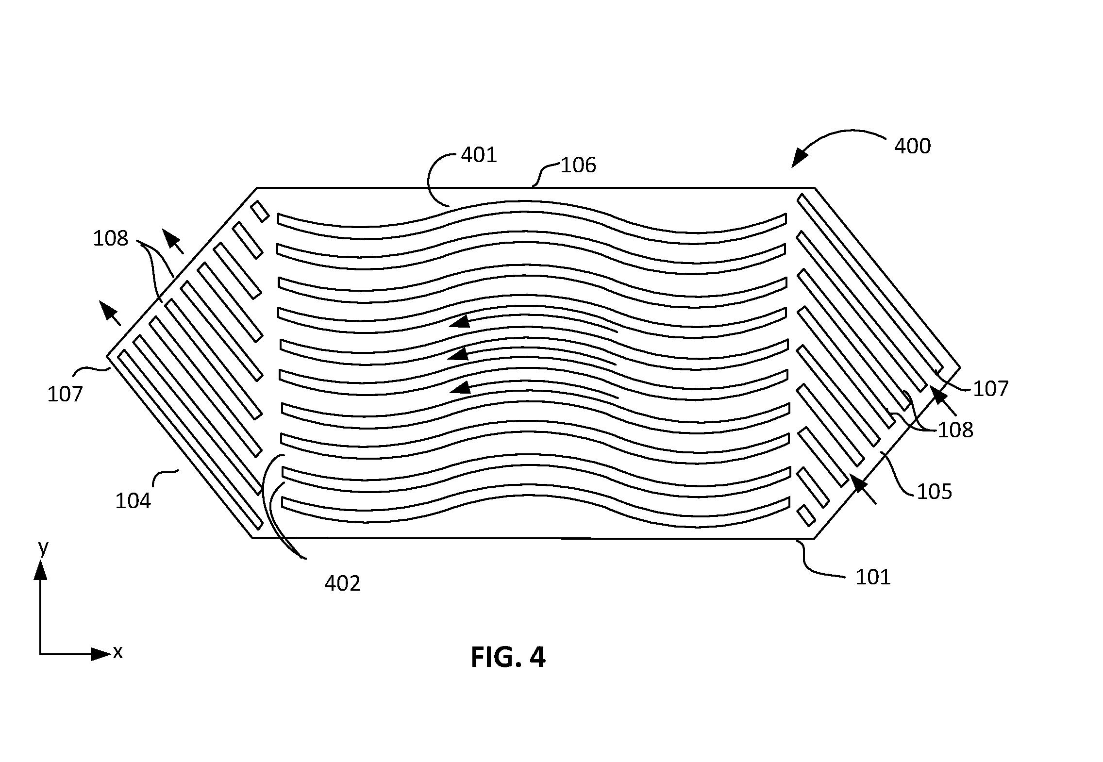
[0065] FIG. 4 illustrates a plan view in the x-y plane of HMX membrane unit 400 having serpentine fin rib support structures 401, according to some embodiments of the disclosure.
[0066] HMX membrane unit 400 comprises serpentine (curved) strip fins 401 extending laterally across main body 106 of membrane 101. Stipfin ribs 401 provide are integrated onto membrane 101, and divide the main airflow channel over membrane 101 into curved subchannels 402. In some embodiments, strip fins 401 have a z-height ranging between 1 mm and 4 mm, extending over membrane 101. In some embodiments, the height of the main airflow channel over membrane 101 (e.g., between membrane 101 and the membrane floor of an adjacent HMX membrane unit 400 in a HMX core stack (not shown)) is substantially equal to the z-height of curved strip fins 401. Curved strip fins 401 have a width extending generally in the y-direction of the figure, ranging between 1 mm and 2 mm. In some embodiments, strip fins 401 have a height-to-width aspect ratio ranging between 1:1 and 2:1. In some embodiments, strip fins 401 comprise an adhesive material, such as, but not limited to, silicones, epoxy resins or acrylate resins. The adhesive material is bonded to membrane 101 by adhesive bonds that are formed during manufacture, as described below.
[0067] In the illustrated embodiment, curved strip fins 401 comprise three curved segments. In some embodiments, curved strip fins 401 are S-shaped, comprising two alternately curved segments. In alternative embodiments curved strip fins 401 comprise four or more curved segments. It will be appreciated by persons skilled in the art that the greater the number and curvature of the curved segments, the greater the length of the airflow path along subchannels 402. The curvature increases the flow path length of subchannels 402 for a given lateral extent relative to straight subchannels (e.g., subchannels 103 shown in FIG. 1). As for HMX membrane units 300a and 300b, more contact surface area is thus provided for heat and mass exchange within curved subchannels 402 without necessitating an increase in the length of membrane 101.
[0068] In some embodiments, the overall dimensions and material compositions described for HMX membrane unit 100 are generally applicable to HMX membrane unit 400. Trangular-shaped headers 104 and 105 extend from the ends of membrane 101
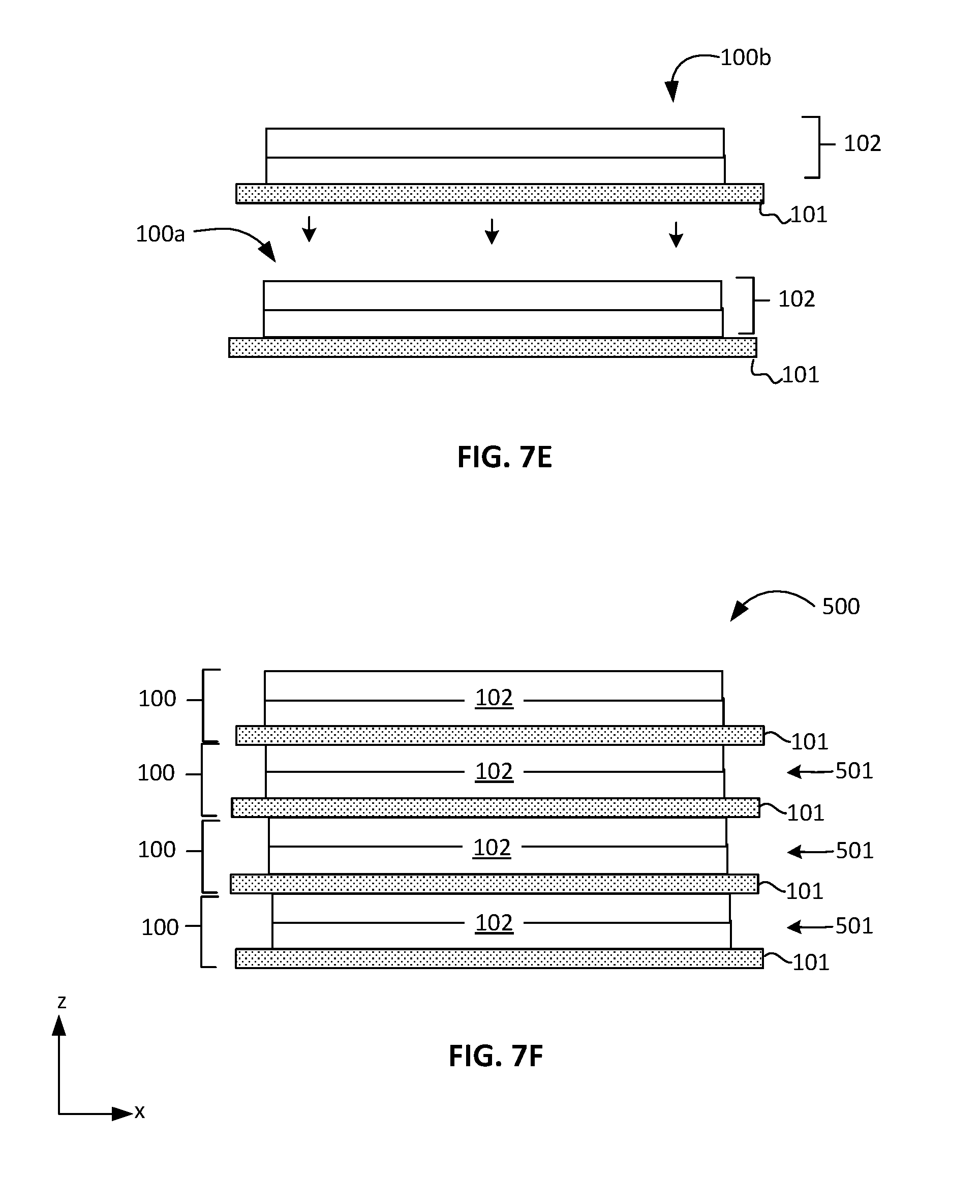
[0069] FIG. 5 illustrates a partially exploded oblique view of HMX core assembly 500 comprising a stack of HMX membrane units 100, according to some embodiments of the disclosure.
[0070] In the illustrated embodiment, HMX core assembly 500 comprises multiple HMX membrane units 100 (shown individually in the exploded view) assembled into a stack extending in the z-direction of the figure. Integrated support structures (e.g., strip fins 102) extend between HMX membrane units, and have adhesive bond joints with the base membrane (e.g., membrane 101) of the HMX membrane unit, and with the base membrane of an adjacent HMX membrane unit within the core stack. The space between each pair of adjacent base membranes is a main flow channel (e.g., main flow channels 501). It will be appreciated that any of the embodiments of HMX membrane units (e.g., HMX membrane units 200, 300a, 300b and 400) described above may be substituted for HMX membrane units 100. In some embodiments, overall dimensions for HMX core assembly comprise a length extending in the x-direction of the figure ranging between 500 mm and 1000 mm, a width extending in the y-direction of the figure ranging between 150 mm and 200 mm, and a height extending in the z-direction of the figure ranging between 750 mm and 1250 mm. In some embodiments, HMX core assembly comprises between 700 and 1000 HMX membrane units 100.
[0071] Individual HMX membrane units are bonded though the integrated support structures (e.g., strip fins 101) extending from the base HMX membrane (e.g., membrane 101) of one HMX membrane unit to the base membrane of an adjacent HMX membrane unit within the core stack. The support structures (e.g., strip fins 102) comprise an adhesive material, and may be bonded to both base membranes by adhesive bond joints formed during assembly of the HMX core stack.
[0072] HMX core assembly 500 comprises multiple HMX membrane units that are structurally coupled to each other by the integrated support structures on each HMX membrane unit. The compounded adhesive bond joints between support structures and adjacent membranes within HMX core assembly 500 produce a rigid stand-alone assembly of HMX membrane units that does not require an external frame or clamping mechanism to hold the membrane units together. The integrated support structures provide the rigidity for each membrane unit and permit the employment of non-rigid, high-performance mass and heat exchange membranes as the base membranes (e.g., membrane 101) for each HMX membrane unit. In the assembly, HMX membrane units 100 are stacked so that headers 104 alternate with headers 105 on each side of HMX core stack 500.
[0073] Bold dark arrows drawn in FIG. 5 indicate exemplary airflow streams that pass internally within HMX core assembly 500, through subchannels 103 of each individual HMX membrane unit. The arrows external to HMX membrane units 100 show the delivery of intake air, generally from the outside, into headers 104, and the exit of the exhaust stream from headers 105. In the illustrated embodiment, adjacent HMX units 100 are stacked such that headers 104 alternate with headers 105 on each side of HMX core assembly 500. HMX membrane units 100a and 100c have overlapping headers 104 on a first side of HMX core stack 500, with header 105 on HMX membrane unit 100b sandwiched in between.
[0074] Referring to HMX membrane units 100a and 100c, intake air directed substantially along the y-direction below the plane of the figure enters headers 104 on the left side of HMX membrane units 100a and 100c and flows along the membrane in the x-direction to headers 105 on the right side, exiting HMX core assembly 500, where the exhaust stream is directed above the plane of the figure aimed substantially along the x- and y-directions of the figure.
[0075] Referring to HMX membrane unit 100b, intake air directed substantially along the x and y directions below the plane or the figure enters header 104 on the right side of the membrane. Air flows along the membrane in the opposite direction relative to air flow in the channels above HMX membrane units 100a and 100c. A countercurrent flow is then established between HMX membrane units 100b and 100a within the main body portions of membrane 101 (e.g., main body 106 shown in FIG. 1), and HMX units 100band 100c. Between vertically alternating headers 104 and 105, a crossflow is established as strip fins 107 in the alternating header regions may be substantially orthogonal to each other or are rotated from each other by an acute or obtuse angle close to 90.degree.. In some embodiments, the flow configuration of HMX core assembly 500 is a quasi-crossflow configuration, as the flow path configuration above and below each membrane 101 results in a partial crossflow within the header portions and a partial countercurrent flow within the main body (e.g., main body 106) portions of membrane 101.
[0076] The alternate orientation of strip fins 107 for each adjacent HMX membrane unit 100 permits opposing airflow streams to be directed in orthogonal or quasi-orthogonal directions on each side of the core. For headers 104 providing air intake along subchannels between strip fins 107, rotated strip fins 107 on interleaved headers 105 block introduction of intake air into the exhaust outlets, so that an intake ERV duct may be coupled to the inlet sides of HMX core assembly 500 and not introduce intake air into the exhaust. This detail is shown in a magnified view in the inset of FIG. 5. Each side receives an intake stream and exhausts an output stream, where the intake and output streams may be collected in separate ducts in the ERV system.
[0077] The large pseudo three-dimensional arrows external to HMX core assembly 500 indicate collective air streams flowing into each side of the core from ERV intake ducts (not shown) and out of each side of the core to ERV exhaust ducts (not shown). Arrows labeled "outside air intake" and "inside air exhaust to outside" indicate airstreams entering HMX core assembly 500 from an intake ERV duct (not shown) coupled to main channels 501 through headers 104 on the right side of the core, and exiting into an exhaust duct leading from main channels 501 through headers 105 on the right side of the core. The ERV ducts (not shown) may be oriented orthogonally or quasi-orthogonally to each other to couple to the right side of HMX core assembly 500, allowing separation of duct work and mitigating mixing of the two air streams.
[0078] The arrow labeled "outside air exhaust to inside" indicates collective flow of conditioned outside air exiting HMX core assembly into a duct leading to the interior of a building from left-side headers 105, and exhausting the conditioned air therein. Not shown is building air entering left-side headers 104 for recovering energy by HMX core assembly 500 from interior air by heat/mass (e.g., mass in the form of water vapor) countercurrent or quasi-cross flow exchange across HMX membrane units 100.
[0079] As mentioned above, subchannels 103 provide flow multiple parallel ducts for the airflow, allowing the bulk airstreams divide upon entry into the core and may increase velocity across the membrane relative to the bulk velocity of the air delivered to HMX core assembly 500 by the ERV system. As an example, the ERV system may deliver an air flow rate of 300 cubic feet per minute (CFM), divided into 704 main channels 501, each comprising 23 subchannels 301, each having a width of approximately 6 mm and a height of approximately 1.2 mm. An increase in flow velocity of the air over the membrane reduces the boundary layer thickness, increasing convective mass and heat transport to the membrane from the bulk airstream passing above. Subchannels 103 also may be extended by folding of strip fins 102, or by multiple flow paths introduced by pillars to increase the effective flow path length, as described above for HMX membrane units 300 and 400, allowing greater contact surface for heat and mass exchange within the same overall membrane size.
[0080] The ability to employ high-performance (e.g., low mass and heat transfer resistance) membranes increase overall heat and mass exchange efficiency of the core with very low pressure drop (e.g., a .DELTA.P of 300 Pa or less), permit a reduction of the overall dimensions of HMX core assembly 500 relative to some currently available HMX cores and offer a more compact HMX core for ERV systems. In addition, a simplified assembly process where manual assembly operations are supplanted by automated operations, as described below, permits lower manufacturing costs to be associated with HMX core assembly 500.
[0081] FIG. 6 illustrates a flow chart of an exemplary method for making HMX core assembly 500, according to some embodiments of the disclosure. The set of operations described below is an illustrated embodiment of the method for making an HMX core assembly according to the embodiments described herein. It will be appreciated that other embodiments of the method that have some variations of the particular operations may be substituted for operations described below.
[0082] At operation 601, a first HMX membrane is received for processing into a HMX membrane unit (e.g., HMX membrane unit 100) and assembled into a HMX core assembly (e.g., HMX core assembly 500). In some embodiments, the HMX membrane is precut to a specified shape, such as, but not limited to, a hexagonal shape as shown in FIGS. 1-5, or a rectangle (e.g., a square shape). In some embodiments, the HMX membrane is supplied on a roller system, where membrane material is fed across an adhesive application station. For the latter, the membrane may be cut in a subsequent operation by a laser cutting operation or a similar cutting operation.
[0083] The HMX membrane may be placed in the workspace of a dispensing station. The dispensing station may comprise a movable nozzle, where the nozzle may be displaced at least vertically (in the z-direction). A pre-cut HMX membrane may be secured to a motorized X-Y stage, where the X-Y stage is computer controlled, using computer numerical control (CNC) techniques.
[0084] At operation 602, a first layer of adhesive is dispensed from the nozzle in a pattern over the membrane. As an example, a strip fin (e.g., strip fin 102) is formed in this and succeeding operations. The adhesive, described above, is dispensed as a paste or a viscous liquid as a continuous bead line as a base layer for the strip fin. The bead may be a line of adhesive that is dispensed from the nozzle while the nozzle is displaced in the x and y-directions along a particular direction. Alternatively, the membrane may be moved on the X-Y table relative to the nozzle, which is held stationary. The beads of adhesive may form tack bonds with the HMX membrane immediately upon contact. The adhesive material may be chosen such that it begins to gradually cure on contact with the air. The length of cure time may be tailored to allow some degree of solidification, but remaining tacky for a specified number of minutes. At the same time, adhesive bonds are formed with the HMX membrane.
[0085] In some embodiments, the beads have a roughly circular cross section. The bead may hold its shape if the adhesive cures internally to an extent where the adhesive does not flow, while remaining tacky on the surface.
[0086] At operation 603, a second bead of adhesive is dispensed over the first bead. The operation may be described as a "writing" of the bead onto the HMX membrane, as the nozzle dispenses the adhesive similarly to a pen dispensing ink over paper. This operation relies on the degree of cross-linking of the adhesive in the first bead allowing the first bead to hold its shape without flowing or deforming under the weight of the second bead. In some embodiments, the second bead is applied in a direction opposite of the first bead. The dispensing head may travel back to a starting position while dispensing the second bead over the first bead. The reversal of the dispensing path may compensate gradually increasing flow of adhesive from the nozzle as the deposition progresses from beginning to the end of the nozzle travel. The bead may be less thick at the beginning and thickest at the end. Commencement of the dispensing of the second bead at the end of the first bead may allow for an even height of the feature, as more adhesive is deposited at the end of the travel, or where deposition of the second bead finishes at the beginning of the first bead.
[0087] As the bead is dispensed, its cross-section may be approximately circular, having a height-to-width aspect ratio of approximately 1:1. An adhesive may be chosen that begins to harden on contact with air as mentioned above, so that the first and second beads do not flatten due to flow under gravity to the extent that the height-to-width aspect ratio significantly reduces to values less than 0.9:1. At the same time, the surface of the bead remains tacky to form adhesive bonds with an overlying bead as well as the underlying HMX membrane. In this way, the structure is built up by two (or more) layers. In some embodiments, the overall height-to-width aspect ratio of the support structure ranges from 1:1 to 2:1. In some embodiments, the overall height-to-width aspect ratio of the support structure (e.g., strip fin 102 or pillar 301) is approximately 1.2:1. To produce an overall aspect ratio of less than 2:1, the thickness of the second bead as dispensed may be less than the thickness of the first layer. The nozzle diameter or the flow rate of the adhesive may be adjusted to produce a desired bead thickness.
[0088] The writing process may be performed at room temperature in ordinary air. In the writing process, each single line (e.g., a strip fin) or pillar is produced at a time. After depositing a single support structure, the nozzle is displaced laterally over the HMX membrane and the next structure is deposited. During this time, the adhesive may continue to slowly cure and still remain tacky at the surface. Adhesives requiring a thermal treatment at elevated temperatures for a final cure are suitable for the writing operation, as they may solidify internally to a large extent relatively slowly at room temperature, but remain tacky enough for the amount of time needed to complete assembling the HMX core assembly.
[0089] As an alternative to the dispensing/writing operation, in some embodiments, a stencil having openings configured in the intended pattern for the support structures is overlaid on the membrane and adhesive is applied by a spraying tool or is applied by a roller. Employment of a stencil may require more than one layer of adhesive to be applied. The nascent structures formed in the openings of the stencil may cure rapidly enough to partially solidify within an allotted time, for example within 5 minutes or less, before additional layers are applied. The particular details of firmness, tackiness and aspect ratio described earlier may apply to the employment of the stencil for simultaneous application of the adhesive.
[0090] Layer thicknesses may range from approximately 0.5 mm to 2 or 3 mm. The target height of the support structure may require application of multiple layers of adhesive to build up the structures to the desired height. For each layer, the deposition process (e.g., writing or through-stencil application) is repeated until the desired height of the structures are reached.
[0091] At operation 604, an optional partial cure is performed to solidify the nascent support structures further than its state of crosslinking in operation 603. The cure step may comprise a thermal treatment at an elevated temperature. In alternative embodiments, a photocure may be performed. Alternatively, a cured adhesive may be activated to a pre-cure stage exhibiting surface tackiness or adhesion, where surface crosslink bonds are re-opened. Restoring adhesive power to the surface of the support structure permits attachment of a second HMX membrane that may be overlaid on the tacky but firm support structure. Activation of adhesion at the surface may comprise chemical treatments with organic solvents or acidic/basic solutions to rupture bonds (e.g., by hydrolysis). In some embodiments, the chemical treatments are performed at temperatures above room temperature.
[0092] At this stage in the process, the support structures have been developed to a desired amount of firmness and surface tack. In some embodiments, the HMX membrane is part of a roll and not cut to the desired shape at this stage. After completion of the pattern of support structures, the portion of the membrane roll is conveyed to a cutting station downstream, and the HMX membrane unit (e.g., HMX membrane unit 100) is cut to shape. At this stage, the HMX membrane unit is completed. The completed HMX membrane unit may be transferred to a subsequent station by a robotic mechanism, or manually, for core stack assembly. In some embodiments, the HMX membrane had been precut before deposition of the support structures. The completed HMX membrane unit comprising the precut HMX membrane may be left in place in the adhesive deposition tool, and a second HMX membrane overlaid in a subsequent operation for formation of the next HMX membrane unit, as described in the following paragraphs.
[0093] At operation 605, the core stack build-up assembly process takes place. In some embodiments, a second HMX membrane (e.g., membrane 101) is aligned to and placed over the completed HMX membrane unit while in the adhesive deposition tool. The transfer and placement operation may be performed by a robotic arm or tool that carries the membrane in a taut state, similar to a pick-and-place operation. The HMX membrane may be carried on a carrier frame over which it is stretched. In some embodiments, the second HMX membrane is pressed against the underlying support structures to ensure that the membrane makes sufficient contact with all of the underlying support structures.
[0094] As mentioned above, the support structures on the underlying HMX membrane unit remain tacky enough to form adhesive bonds with the second HMX membrane. Sufficient bond formation between the underlying structures and the second HMX membrane is necessary to seal the second membrane to the underlying support structures. As an example, subchannels (e.g., subchannels 103 shown in FIG. 1) are separated from one another by strip fin sidewalls (e.g., strip fins 101 shown in FIG. 1) that are integrated with both the first HMX membrane and the overlying second HMX membrane. The integration of the support structures with the HMX membranes is performed by the adhesive bonding of the support structures to the HMX membrane material. Accordingly, the strip fin sidewalls seal the passageways so that airstreams flowing within the subchannels do not mix. In embodiments where the support structures are pillar structures (e.g., elongated pillars 201 shown in FIG. 2 or circular pillars 301 shown in FIGS. 3A and 3B), the pillar structures are integrated to both first and second HMX membranes by formation of adhesive bonds with both membranes. At this stage, the support structures are still partially cured, and may remain tacky. Final curing and solidification of the structures may be carried out in a subsequent operation.
[0095] Once in place over the first HMX membrane unit, the second HMX membrane is ready for processing into a second HMX membrane unit with its own set of support structures. In some embodiments, the process flow cycles back to operation 602 and repeats the operations to operation 605, as indicated in FIG. 6. The process cycle may be repeated a prescribed number of times to build up the HMX core stack. In some embodiments, the process cycle is repeated between 700 and 1000 times.
[0096] At operation 606, the core stack build-up process is complete (e.g., as HMX core assembly 500). In some embodiments, a final curing operation is performed by thermal treatment at elevated temperatures (e.g., at 50.degree. C. or higher). The thermal treatment may be performed in an oven. The curing temperature may be selected to be under the glass transition temperature of the HMX membrane material. A cure time may be adjusted to cure the support structures to a specified rigidity, where the cure time is selected so that the cured structure does not plastically deform more than approximately 2% to maintain the desired shape and dimensions of the structures, particularly the height and lateral dimensions (e.g., the width or diameter). After the final cure, the HMX core stack is complete.
[0097] FIGS. 7A-F illustrate a succession of key operations of an exemplary method to manufacture HMX core assembly 500, according to some embodiments of the disclosure.
[0098] In the operation depicted in FIG. 7A, nozzle 700 is translated over HMX membrane 101 in a first direction along the x-axis (e.g., toward the right side of the figure) to dispense first adhesive bead 701 as a strip fin line (e.g., strip fin 102 shown in FIG. 1) on the surface of HMX membrane 101. Nozzle 700 is positioned over HMX membrane 101 at a z-height that is optimized to dispense first adhesive bead 701 at a prescribed speed of translation (e.g., 250 mm/s) that permits approximately predictable dimensions along the length of first adhesive bead 701 in the x- and z-dimensions. In some embodiments, first adhesive bead 701 is thicker at the end of the write run that at the beginning.
[0099] Nozzle 700 may be mounted on a movable arm that is capable of displacement in the x- and z-directions, and translated with HMX membrane 101 held stationary during the write operation. In some embodiments, Nozzle 700 may be held stationary while HMX membrane 101 is translated on an X-Y table under nozzle 700. Nozzle 700 may be displaced in the z-direction by a movable arm on the dispensing tool, or by displacement of HMX membrane 101 on an X-Y-Z table. As an example, nozzle 700 may be displaced relative to membrane 101 at 250 mm/sec.
[0100] In the operation depicted in FIG. 7B, the writing (e.g., dispensing) of first adhesive bead 701 is complete. Nozzle 700 is positioned above the end portion. In some embodiments, nozzle 700 is displaced to a higher position (in the z-direction) over the end of first adhesive bead 701. In some embodiments, a delay or hold time is imposed between write runs to allow first adhesive bead to set or partially cure to a point where it is firm (e.g., still deformable under sufficient strain) but tacky (e.g., still able to form adhesive bonds). In some embodiments, multiple nozzles are employed. In some embodiments, the width of adhesive bead 701 is approximately 0.5 mm as deposited.
[0101] In the operation depicted in FIG. 7C, nozzle 700 is translated in the reverse direction over first adhesive bead 701 to write second adhesive bead 702 directly over first adhesive bead 701. In some embodiments, the speed of translation of nozzle 700 (relative to HMX membrane 101) to write second adhesive bead 702 is substantially the same as the first write operation to form first adhesive bead 701.
[0102] In some embodiments, the amount of adhesive to form second adhesive bead 702 is less than the amount used for formation of first adhesive bead 701. In general, a lesser amount of adhesive to for the second layer may be necessary to control the height dimension or the height-to-lateral dimension (e.g., width or diameter) aspect ratio of the support structure. As an example, a desired aspect ratio may be 1.2:1. To achieve the target aspect ratio, the amount of adhesive dispensed to form second adhesive bead 702 may be 50% to 80% less than the amount of adhesive dispensed to form first adhesive bead 701.
[0103] In the operation depicted in FIG. 7D, the writing of second adhesive bead 702 is complete. A delay or hold time may be imposed to allow second adhesive bead 702 to set or partially cure to a point where it is firm (e.g., still deformable under sufficient strain) but tacky (e.g., still able to form adhesive bonds). At this stage, formation of strip fin 102 is complete and integrated onto HMX membrane 101. The write operations depicted in FIGS. 7A through 7C may be repeated a number of times (e.g., 20-40 times) on HMX membrane 101 to complete an array of strip fins 102, as shown in FIG. 1. After completion of the strip fin array, comprising strip fins 102 and 107 (not shown), HMX membrane unit 100 is completed. In some embodiments, multiple nozzles are employed in parallel to reduce the duration of the write operations.
[0104] In the operation depicted in FIG. 7E, the assembly process to make HMX core assembly 500 is shown where multiple HMX membrane units 100a and 100b are stacked. The stacking process may be performed by a robotic arm. Some details of this procedure are described above in the discussion relating to FIG. 6. As an example, HMX membrane unit 100b is aligned over HMX membrane unit 100a and lowered to make contact between strip fins 102 on HMX membrane unit 100a and HMX membrane 101 of HMX membrane unit 100b. Tack bonds may be formed between strip fins 102 and overlying HMX membrane material to seal strip fins 102 to the overlying HMX membrane.
[0105] In the operation depicted in FIG. 7F, a representative portion of an assembled HMX core assembly 500 comprising a stack of multiple HMX membrane units 100 is shown. The core stack is mechanically bonded together by the adhesive bonds between strip fins 102 between each sheet of HMX membrane 101, forming a rigid unit without the aid of an external framework or mechanical supports. Main airflow channels 501 are formed in the space between HMX membrane units 100 and extend above and below the plane of the figure, in the y-direction. The height of main airflow channels 501 is determined the z-height of strip fins 102, which also form the sidewalls of the subchannel array (e.g., subchannels 301 in FIG. 1) extending along the x- and y-directions.
[0106] FIG. 8 illustrates flow chart 800 summarizing an alternative method for making HMX core assembly 500, according to some embodiments of the disclosure. It will be appreciated that other embodiments of the method that have some variations of the particular operations may be substituted for operations described below.
[0107] At operation 801, an in-process HMX core stack (e.g., HMX core assembly 500) is received for further processing. The HMX core stack may comprise a platen holding a single blank HMX membrane, or it may comprise multiple pre-assembled HMX membrane units (e.g., HMX membrane units 100) assembled together into an unfinished core stack. It will be understood that by "unfinished" refers to a core stack having fewer than the target number of HMX membrane units assembled together and is still in-process. The core stack has a top HMX membrane that is blank, meaning that it does not have any adhesive material deposited over it. The assembly process comprises multiple bonding cycles, each bonding cycle producing a HMX membrane unit addition to the HMX core stack.
[0108] At operation 802, an adhesive is deposited over the top HMX membrane to from an array of integrated support structures. Suitable adhesive materials that may be deposited over the HMX membrane have been described in detail above. A criterion of the adhesive is that it non-slumping, meaning it does not flow under its own weight during the open time (e.g., in the pre-cured state), maintaining its as-deposited shape.
[0109] In some embodiments, the deposition process is a nozzle-dispensing process as described above, and shown in FIGS. 7A-7F. In this process, beads of adhesive are extruded through the nozzle. The dispensed bead may hold its shape substantially as-extruded. In contrast to the multi-layer dispense process described earlier, a single layer of adhesive may be deposited over the blank HMX membrane. In alternate embodiments, the adhesive is applied through a stencil as a deposition mask. Here, the adhesive may be deposited by a roller over a stencil having a through-mask pattern of openings delineating the support structure array. The width of elongated structures (e.g., strip fins 102 or elongated pillars 201) as defined by the stencil mask may be wider than the target dimension.
[0110] At operation 803, a blank and unattached HMX membrane is mounted on a platen. The blank HMX membrane may be precut to the intended dimensions and shape. In some embodiments, the HMX membrane is cut to a hexagonal shape, as shown in FIGS. 1-4. The platen may comprise a vacuum mounting system, or a vacuum chuck. The vacuum firmly holds the HMX membrane, which is highly compliant, on a flat surface. The membrane may be mounted on the platen in a taut manner such that there are no wrinkles.
[0111] In some embodiments, the platen may be part of or entirely an end effector (e.g., the manipulating mechanism of a robot arm) of a robotic arm capable of motion in three dimensions. In alternate embodiments, the platen may be an end effector of a linear actuator capable only of motion along a single axis, for example, vertical motion in the z-direction.
[0112] At operation 804, the platen may be rotated to face the blank HMX membrane downward, or opposite the top membrane having the freshly deposited patterned adhesive layer on the HMX core stack. The platen is then lowered by vertical displacement in the z-direction to tack the blank membrane on the patterned adhesive layer on the top HMX membrane of the core stack. The platen motion may be controlled in such a way that the contact pressure is adjusted so that no gaps exist between the adhesive beads and the HMX membrane. The adhesive beads may be firm, but not solid enough to resist significant strain, where the adhesive may deform plastically. Adhesive bonding takes place between the blank HMX membrane and the adhesive beads, and the blank HMX membrane is tacked down on the patterned adhesive layer.
[0113] At operation 805, the platen is raised by upward motion in the z-direction by several tens or hundreds of microns over the as-deposited height of the adhesive bead. At the same time, the membrane remains bonded to the adhesive, and is pulled upward, stretching and elongating the adhesive beads in the z-direction beyond the elastic limit. The adhesive forces may be strong enough to remain intact during the stretching process. According to some embodiments, the platen is raised a distance that substantially goes beyond the elastic deformation limit of the adhesive material in the uncured state.
[0114] In some embodiments, the distance above the top HMX membrane to which the platen is raised is substantially the target height of the final structure after curing. At the same time, the width of the bead may decease as material is pulled upward. In some embodiments, the adhesive bead is plastically deformed and assumes the new dimensions of at the height and width as a result of the stretching process. According to some embodiments, the adhesive is firm enough as a result of partial curing at room temperature, to retain the shape assumed by the plastic deformation. As an example, the adhesive bead may be stretched a distance above the as-deposited adhesive beads to attain a height-to-width aspect ratio between 1:1 and 2:1 (e.g., the aspect ratio is adjusted to 1.2:1). When this operation is completed, the HMX membrane and integrated structures form a HMX membrane unit (e.g., HMX membrane unit 101)
[0115] At operation 806, the blank HMX membrane is released from the platen. The blank HMX membrane is tacked to the top adhesive layer and raised to the target height. To release the membrane, the vacuum may interrupted if a vacuum chuck or vacuum mounting system is employed. Once released, the blank membrane is the top HMX membrane of the in-process core stack. The platen is available to retrieve another blank membrane to add to the core stack by repeating the bonding cycle as described in operations 802-806. As indicated in FIG. 8, the process cycles back to operation 802.
[0116] At operation 807, the core stack is complete. By being complete, it is meant that the target number of HMX membrane units have been assembled in the core stack build-up cycle comprising operations 802-806. The entire core stack may be cured at an elevated temperature, as described for operation 606 in FIG. 6.
[0117] FIGS. 9A-9I illustrate a succession of key operations of an alternate exemplary method for making HMX core assembly 500, according to some embodiments of the disclosure.
[0118] In the operation depicted in FIG. 9A, an in-process HMX core assembly 500, where the core stack is unfinished. The target number of HMX membrane units 100 has not yet been attained. Multiple HMX membrane units 100 are tack-bonded together in a stack that is built up by the operations in the exemplary manufacturing process described in the following paragraphs. At any stage of completion, the in-process HMX core stack is capped by top HMX membrane 900, which is tacked onto the adhesive layer of the lower HMX membrane unit produced in the previous bonding cycle. There are no structures integrated over top HMX membrane 900 at this stage. The operations are part of a cyclic bonding process to manufacture the HMX core stack (e.g., HMX core assembly 500) by a build-up method. Each bonding cycle produces a HMX membrane unit 100.
[0119] In the operation depicted in FIG. 9B, adhesive bead 901 is dispensed from nozzle 902, which is positioned at a z-height above top membrane 900 and translated over it along the x-direction in the figure. The adhesive bead 901 is extruded from the nozzle and has an as-deposited z-height and width as the nozzle travels along the membrane. When deposited on the membrane, adhesive bead 901 may have an approximately circular cross section. In some embodiments, multiple nozzles may be employed in parallel. As described above, suitable adhesives are non-slumping, in that the adhesive material does not flow under gravity after deposition, substantially retaining its as-deposited shape until it cures. In some embodiments, the width of adhesive bead 901 is approximately 0.5 mm as deposited.
[0120] The deposition of adhesive bead 901 may be performed by a similar method described for FIGS. 7A and 7B. In some embodiments, nozzle 902 translates while HMX core assembly 500 remains stationary. In some embodiments, HMX core assembly 500 is mounted on an x-y table and translated while nozzle 902 remains stationary. The relative motion of nozzle 902 relative to top HMX membrane 900 may be computer controlled (e.g., by CNC operation) to follow coded write commands to produce a pattern of structures created by multiple beads of similar or different lengths and orientations. As an example, nozzle 902 is translated at a speed of approximately 250 mm/sec relative to HMX membrane 900.
[0121] In the operation depicted in FIG. 9C, the writing of bead 901 is completed. As an example, bead 901 is written to form a strip fin 102. An array of strip fins 102 may be created in this manner by displacement of nozzle 902 in the y-direction of the figure and repeating the x-translation. The adhesive remains firm but tacky, holding its shape. At the same time, adhesive bead 901 forms adhesive bonds with top HMX membrane 900.
[0122] In the operation depicted in FIG. 9D, blank membrane 903 is mounted on platen 904. In some embodiments, platen 904 is an end effector of a robotic arm (not shown). In some embodiments, platen 904 is attached to a linear actuator that translates in the z-direction of the figure. In some embodiments, blank membrane 903 is held by vacuum on platen 904, where a blank membrane 903 is sucked onto a mesh that is incorporated into platen 904. In alternate embodiments, blank membrane 903 is held onto platen 904 by a mechanical clamping mechanism.
[0123] In the operation depicted in FIG. 9E, platen 904 is aligned over HMX core assembly 500 and lowered to tack blank membrane 903 onto adhesive bead 901. In FIG. 9E, adhesive bead 901 represents an entire array of nascent support structures written onto top HMX membrane 900 in FIGS. 9B and 9C. In the operation depicted in FIG. 9F, blank membrane 903 makes contact with adhesive bead 901. Adhesive bonds begins to form and hold it onto the nascent support structure. During the attachment of blank membrane 903 to adhesive bead 901, platen 904 remains attached to blank membrane 903.
[0124] In the operation depicted in FIG. 9G, platen 904 is translated upward in the z-direction by distance .DELTA.h, which may be tens or hundreds of microns. In some embodiments, .DELTA.h is larger than the elastic limit of the adhesive material, and the material undergoes plastic deformation. During this operation, vacuum may hold blank membrane 903 onto platen 904, if a vacuum chuck is employed. Membrane 903 moves upward with platen 904, pulling the top portion of adhesive bead 901 upward with it by tensile force as adhesive bonds between bead 901 and blank membrane 903 are strong enough to remain attached to the surfaces of blank membrane 903 above and top membrane 900 below.
[0125] The dimensions of adhesive bead 901 are stretched by the tensile forces imposed during this operation, where adhesive bead 901 attains a new z-height that is greater than the initial as-deposited z-height. Adhesive bead 901 undergoes plastic deformation during this stretching operation. In some embodiments, platen 904 is held at the raised position for a prescribed period of time to allow plastic deformation to occur. During the hold time, the polymer chains may relax into the stretched configuration, and lose their propensity to recoil back into the original shape as elastic strain is exceeded.
[0126] At the same time, the width of adhesive bead 901 may decrease as tensile forces lift material from the sidewalls of adhesive bead 901 to build up the z-height. The height-to-width aspect ratio may be adjusted in this manner to values between 1:1 and 2:1. As an example, the height-to-width aspect ratio of the nascent strip fin structure may be 1.2:1. The aspect ratio may be important to ensure sufficient height of the airflow channels (e.g., airflow channels 501) to maintain small pressure drop (e.g., less than 300 Pa) across the airflow channels, while at the same time limiting coverage of the active membrane surface by the structure to ensure high efficiency of heat and mass transfer across the HMX membranes.
[0127] In the operation depicted in FIG. 9H, formation of the new HMX membrane unit 100 is completed on the core stack. Adhesive bead 901 is now strip fin 102, having a target z-height and aspect ratio. Blank membrane 903 is now top membrane 900. In the operation depicted in FIG. 9I, the bonding cycle is complete. Platen 904 is released from top membrane 900 and raised upward in the z-direction. HMX core assembly 500 has an additional HMX membrane unit 100 and a top membrane 900 ready to undergo a new bonding cycle in the operations of FIGS. 9A-9I. The bonding cycles may be repeated until HMX core assembly 500 comprises a target number of HMX membrane units 100. In some embodiments, the core stack comprises between 500 and 100 units.
[0128] Subsequent to the completion of the core stack assembly, HMX core assembly 500 may undergo a thermal treatment at elevated temperatures to cure the adhesive material. The curing operation may be performed to solidify the support structures and strengthen the adhesive bonds to membranes above and below the airflow channels (e.g., airflow channels 501) in the core stack. A cure time may be adjusted to cure the support structures to a specified rigidity, where the cure time is selected so that the cured structure does not plastically deform more than approximately 2% to maintain the desired shape and dimensions of the structures, particularly the height and lateral dimensions (e.g., the width or diameter). After the final cure, the HMX core stack is complete.
[0129] Reference in the specification to "an embodiment," "one embodiment," "some embodiments," or "other embodiments" means that a particular feature, structure, or characteristic described in connection with the embodiments is included in at least some embodiments, but not necessarily all embodiments. The various appearances of "an embodiment," "one embodiment," or "some embodiments" are not necessarily all referring to the same embodiments. If the specification states a component, feature, structure, or characteristic "may," "might," or "could" be included, that particular component, feature, structure, or characteristic is not required to be included. If the specification or claim refers to "a" or "an" element, that does not mean there is only one of the elements. If the specification or claims refer to "an additional" element, that does not preclude there being more than one of the additional element.
[0130] Furthermore, the particular features, structures, functions, or characteristics may be combined in any suitable manner in one or more embodiments. For example, a first embodiment may be combined with a second embodiment anywhere the particular features, structures, functions, or characteristics associated with the two embodiments are not mutually exclusive.
[0131] While the disclosure has been described in conjunction with specific embodiments thereof, many alternatives, modifications and variations of such embodiments will be apparent to those of ordinary skill in the art in light of the foregoing description. The embodiments of the disclosure are intended to embrace all such alternatives, modifications, and variations as to fall within the broad scope of the appended claims.
[0132] In addition, well known power/ground connections to integrated circuit (IC) chips and other components may or may not be shown within the presented figures, for simplicity of illustration and discussion, and so as not to obscure the disclosure. Further, arrangements may be shown in block diagram form in order to avoid obscuring the disclosure, and also in view of the fact that specifics with respect to implementation of such block diagram arrangements are highly dependent upon the platform within which the present disclosure is to be implemented (i.e., such specifics should be well within purview of one skilled in the art). Where specific details (e.g., circuits) are set forth in order to describe example embodiments of the disclosure, it should be apparent to one skilled in the art that the disclosure can be practiced without, or with variation of, these specific details. The description is thus to be regarded as illustrative instead of limiting.
[0133] An abstract is provided that will allow the reader to ascertain the nature and gist of the technical disclosure. The abstract is submitted with the understanding that it will not be used to limit the scope or meaning of the claims. The following claims are hereby incorporated into the detailed description, with each claim standing on its own as a separate embodiment.
* * * * *
D00000
D00001
D00002
D00003
D00004
D00005
D00006
D00007
D00008
D00009
D00010
XML
uspto.report is an independent third-party trademark research tool that is not affiliated, endorsed, or sponsored by the United States Patent and Trademark Office (USPTO) or any other governmental organization. The information provided by uspto.report is based on publicly available data at the time of writing and is intended for informational purposes only.
While we strive to provide accurate and up-to-date information, we do not guarantee the accuracy, completeness, reliability, or suitability of the information displayed on this site. The use of this site is at your own risk. Any reliance you place on such information is therefore strictly at your own risk.
All official trademark data, including owner information, should be verified by visiting the official USPTO website at www.uspto.gov. This site is not intended to replace professional legal advice and should not be used as a substitute for consulting with a legal professional who is knowledgeable about trademark law.