Remote Monitoring System And Relay Device Used Therefor
MAEKAWA; Yoshihiko ; et al.
U.S. patent application number 16/195879 was filed with the patent office on 2019-05-30 for remote monitoring system and relay device used therefor. This patent application is currently assigned to Noritz Corporation. The applicant listed for this patent is Noritz Corporation. Invention is credited to Yoshihiko MAEKAWA, Akihiko TSUGAWA.
| Application Number | 20190162425 16/195879 |
| Document ID | / |
| Family ID | 66632249 |
| Filed Date | 2019-05-30 |
| United States Patent Application | 20190162425 |
| Kind Code | A1 |
| MAEKAWA; Yoshihiko ; et al. | May 30, 2019 |
REMOTE MONITORING SYSTEM AND RELAY DEVICE USED THEREFOR
Abstract
The disclosure provides a remote monitoring system for remotely acquiring various information related to a hot water utilizing facility in an appropriate period, and a relay device used therefor. The remote monitoring system includes: a hot water utilizing facility; a relay device communicating with the hot water utilizing facility; and a management device communicating with the relay device via a communication network. The management device is configured to transmit to the relay device a command for acquiring information related to the hot water utilizing facility at a set transmission interval over a set transmission period. The relay device includes an information acquisition part acquiring at least one piece of information from a plurality of types of information related to the hot water utilizing facility according to the command transmitted from the management device and transmitting it to the management device. The transmission period is configured so that setting is changeable.
| Inventors: | MAEKAWA; Yoshihiko; (Akashi-shi, JP) ; TSUGAWA; Akihiko; (Akashi-shi, JP) | ||||||||||
| Applicant: |
|
||||||||||
|---|---|---|---|---|---|---|---|---|---|---|---|
| Assignee: | Noritz Corporation HYOGO JP |
||||||||||
| Family ID: | 66632249 | ||||||||||
| Appl. No.: | 16/195879 | ||||||||||
| Filed: | November 20, 2018 |
| Current U.S. Class: | 1/1 |
| Current CPC Class: | G05B 15/02 20130101; F24D 19/1051 20130101; F24H 9/2035 20130101; F24D 19/1063 20130101; G06F 3/01 20130101 |
| International Class: | F24D 19/10 20060101 F24D019/10; F24H 9/20 20060101 F24H009/20 |
Foreign Application Data
| Date | Code | Application Number |
|---|---|---|
| Nov 27, 2017 | JP | 2017-226611 |
Claims
1. A remote monitoring system, comprising: a hot water utilizing facility; a relay device communicating with the hot water utilizing facility; and a management device communicating with the relay device via a communication network, wherein the management device is configured to transmit to the relay device a command for acquiring information related to the hot water utilizing facility at a set transmission interval over a set transmission period, the relay device comprises an information acquisition part acquiring at least one piece of information from a plurality of types of information related to the hot water utilizing facility according to the command transmitted from the management device and transmitting the at least one piece of information to the management device, and the transmission period is configured to have a setting changeable.
2. The remote monitoring system according to claim 1, wherein the transmission interval is configured to have a setting changeable.
3. The remote monitoring system according to claim 2, wherein a range of the transmission interval settable according to the transmission period is set, or a range of the transmission period settable according to the transmission interval is set.
4. The remote monitoring system according to claim 1, wherein the management device comprises a notification part notifying a user that the transmission period has ended.
5. The remote monitoring system according to claim 1, wherein the management device comprises an item display part displaying a plurality of types of items related to the hot water utilizing facility on a display device connected to the management device to be selectable and inputable, and the management device transmits to the relay device the command for acquiring information corresponding to at least one item selected and input on the item display part.
6. A relay device used for the remote monitoring system according to claim 1.
7. The remote monitoring system according to claim 2, wherein the management device comprises a notification part notifying a user that the transmission period has ended.
8. The remote monitoring system according to claim 3, wherein the management device comprises a notification part notifying a user that the transmission period has ended.
9. The remote monitoring system according to claim 2, wherein the management device comprises an item display part displaying a plurality of types of items related to the hot water utilizing facility on a display device connected to the management device to be selectable and inputable, and the management device transmits to the relay device the command for acquiring information corresponding to at least one item selected and input on the item display part.
10. The remote monitoring system according to claim 3, wherein the management device comprises an item display part displaying a plurality of types of items related to the hot water utilizing facility on a display device connected to the management device to be selectable and inputable, and the management device transmits to the relay device the command for acquiring information corresponding to at least one item selected and input on the item display part.
11. The remote monitoring system according to claim 4, wherein the management device comprises an item display part displaying a plurality of types of items related to the hot water utilizing facility on a display device connected to the management device to be selectable and inputable, and the management device transmits to the relay device the command for acquiring information corresponding to at least one item selected and input on the item display part.
12. The remote monitoring system according to claim 7, wherein the management device comprises an item display part displaying a plurality of types of items related to the hot water utilizing facility on a display device connected to the management device to be selectable and inputable, and the management device transmits to the relay device the command for acquiring information corresponding to at least one item selected and input on the item display part.
13. The remote monitoring system according to claim 8, wherein the management device comprises an item display part displaying a plurality of types of items related to the hot water utilizing facility on a display device connected to the management device to be selectable and inputable, and the management device transmits to the relay device the command for acquiring information corresponding to at least one item selected and input on the item display part.
14. A relay device used for the remote monitoring system according to claim 2.
15. A relay device used for the remote monitoring system according to claim 3.
16. A relay device used for the remote monitoring system according to claim 4.
17. A relay device used for the remote monitoring system according to claim 5.
18. A relay device used for the remote monitoring system according to claim 7.
19. A relay device used for the remote monitoring system according to claim 8.
20. A relay device used for the remote monitoring system according to claim 9.
Description
CROSS-REFERENCE TO RELATED APPLICATION
[0001] This application claims the priority benefit of Japan application serial no. 2017-226611, filed on Nov. 27, 2017. The entirety of the above-mentioned patent application is hereby incorporated by reference herein and made a part of this specification.
BACKGROUND
Technical Field
[0002] The disclosure relates to a remote monitoring system for remotely monitoring a hot water utilizing facility, such as a water heater, and a relay device used therefor.
Description of Related Art
[0003] Conventionally, the hot water utilizing facility, such as a water heater, has a function (referred to as maintenance monitoring function, etc., for example) of acquiring information related to the hot water utilizing facility from an operation terminal, such as a remote controller, that comes with the hot water utilizing facility. By using the maintenance monitoring function, the service person of the hot water utilizing facility can select a predetermined item corresponding to desired information from the operation terminal to acquire the corresponding information (incoming water temperature, discharged hot water temperature, load voltage, etc., for example) at a predetermined time interval in a predetermined period.
[0004] Furthermore, a remote monitoring system is known for remotely monitoring and operating facility equipment with use of a communication terminal, such as a mobile phone. Several configurations have been proposed for operating facility equipment from a communication terminal, such as a tablet PC, or a remote management device, instead of the remote controller that comes with the hot water utilizing facility and serves as the operation terminal of the maintenance monitoring function (see Japanese Patent Application Laid-open No. 2013-204845 and No. 2017-67336, for example).
[0005] Since the above configurations are made from the aspect of using the communication terminal, etc. as a substitute for the remote controller of the equipment, it is assumed that the service person will go to the place where the hot water utilizing facility is installed to verify it. Therefore, the period of maintenance monitoring has been preset to a predetermined short period (about 10 minutes to 30 minutes, for example) regardless of whether it is performed from the remote controller or the communication terminal, etc. Thus, the conventional configurations have not been made to allow the service person to carry out long-term verification by using the communication terminal, etc. without visiting the place where the hot water utilizing facility is installed. In addition, depending on the information to be acquired (item to be selected) or the content to be verified, the periods of information acquisition may differ from each other. In such cases, the desired information cannot be properly acquired with the conventional configuration.
SUMMARY
[0006] A remote monitoring system according to an embodiment of the disclosure includes: a hot water utilizing facility; a relay device communicating with the hot water utilizing facility; and a management device communicating with the relay device via a communication network. The management device is configured to transmit to the relay device a command for acquiring information related to the hot water utilizing facility at a set transmission interval over a set transmission period. The relay device includes an information acquisition part acquiring at least one piece of information from a plurality of types of information related to the hot water utilizing facility according to the command transmitted from the management device and transmitting the at least one piece of information to the management device. The transmission period is configured to have a setting changeable.
[0007] A relay device according to another embodiment of the disclosure is used for the remote monitoring system having the above configuration.
Effects
BRIEF DESCRIPTION OF THE DRAWINGS
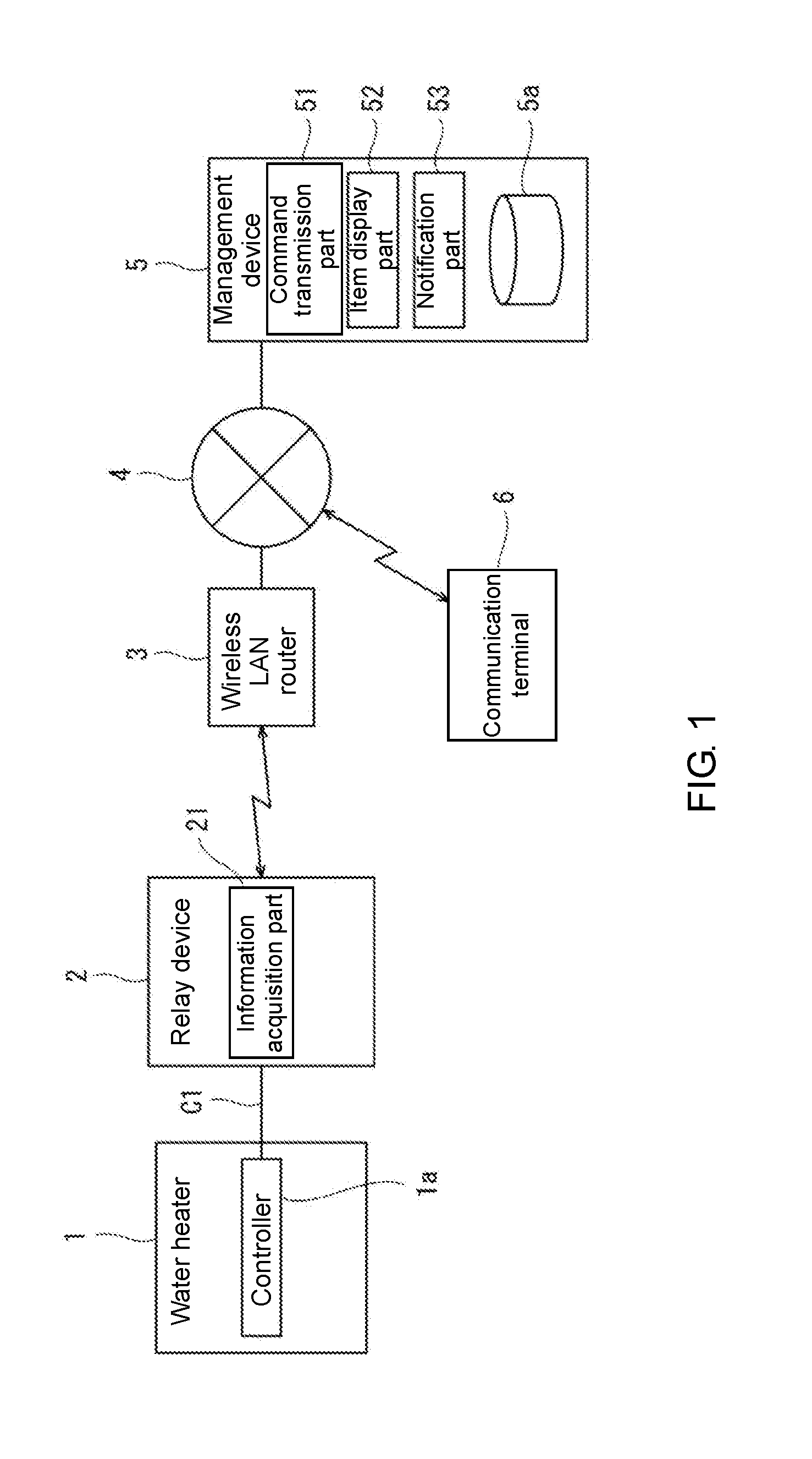
[0008] FIG. 1 is a schematic configuration diagram showing an example of the remote monitoring system according to an embodiment of the disclosure.
[0009] FIG. 2 is a diagram showing an example of the maintenance monitoring screen displayed on the display device of the management device according to the present embodiment.
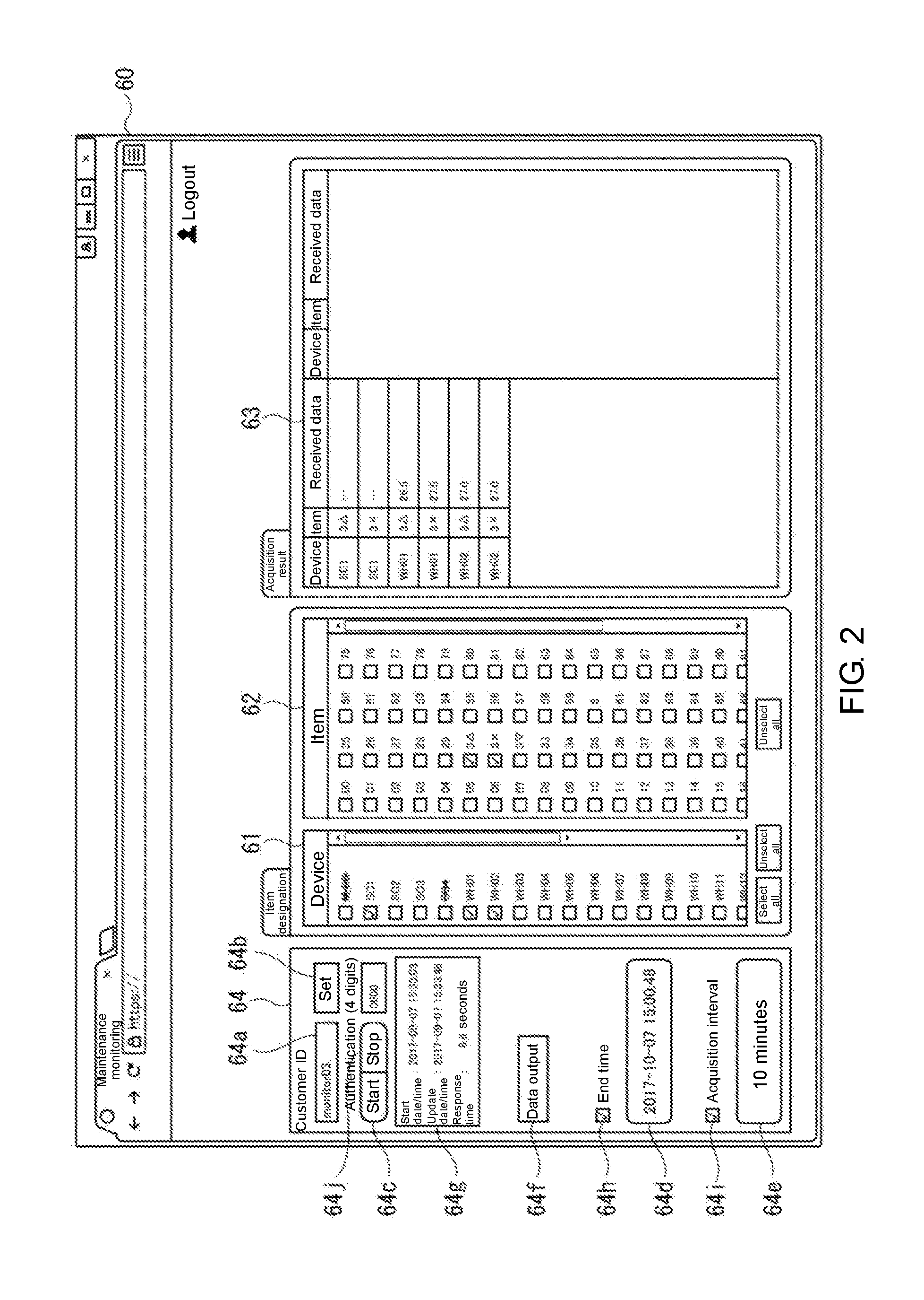
[0010] FIG. 3 is a diagram showing an example of the end time setting screen according to the present embodiment.
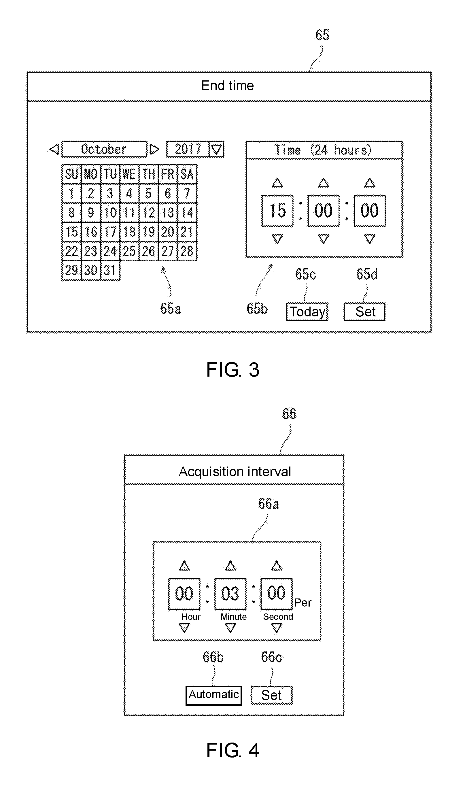
[0011] FIG. 4 is a diagram showing an example of the acquisition interval setting screen according to the present embodiment.
DESCRIPTION OF THE EMBODIMENTS
[0012] The disclosure provides a remote monitoring system that is capable of acquiring various information related to the hot water utilizing facility remotely in an appropriate period, and a relay device used therefor.
[0013] According to the above configuration, the command for acquiring information related to the hot water utilizing facility is sent from the management device to the relay device at the predetermined transmission interval in the predetermined transmission period, and accordingly the relay device acquires the corresponding information from the hot water utilizing facility. At this time, the transmission period for transmitting the command is configured so that the setting is changeable. That is, the user such as the service person can set the acquisition period of the desired information to any period by setting the transmission period for transmitting the command according to the desired information. Therefore, with the above configuration, it is possible to acquire various information related to the hot water utilizing facility remotely in an appropriate period.
[0014] The transmission interval may be configured to have a setting changeable. Therefore, the acquisition interval of the desired information can also be set to any interval according to the acquisition period of the desired information.
[0015] A range of the transmission interval settable according to the transmission period may be set, or a range of the transmission period settable according to the transmission interval may be set. Thus, for example, when the transmission period is long, the transmission interval is lengthened accordingly; and when the transmission period is short, the transmission interval is shortened accordingly. Therefore, for example, when the transmission period to be set is long, by lengthening the transmission interval accordingly, it is possible to prevent excessive communication traffic. In addition, when it is desired to see a local value change, by setting both the transmission period and the transmission interval short, it is possible to acquire a local value change at a pinpoint and to prevent the acquired information from becoming redundant.
[0016] The management device may include a notification part notifying a user that the transmission period has ended. Therefore, it is possible to notify the user of the acquisition of information with the end of the transmission period and to prevent causing inconvenience to the user even when the setting of the transmission period is changed.
[0017] The management device may include an item display part displaying a plurality of types of items related to the hot water utilizing facility on a display device connected to the management device to be selectable and inputable, and the management device may transmit to the relay device the command for acquiring information corresponding to at least one item selected and input on the item display part. Therefore, by selecting multiple types of items displayed by the item display part, the desired information can be designated easily.
[0018] The disclosure provides a remote monitoring system that is capable of acquiring various information related to the hot water utilizing facility remotely in an appropriate period, and a relay device used therefor.
[0019] Hereinafter, exemplary embodiments will be described with reference to the drawings. In the following description, the same or equivalent elements are denoted by the same reference numerals throughout the drawings and repeated descriptions thereof will be omitted. In addition, the disclosure is not limited to the following embodiments.
[0020] FIG. 1 is a schematic configuration diagram showing an example of a remote monitoring system according to an embodiment of the disclosure. The remote monitoring system includes a water heater 1 (combustion heating water heater, for example) which is an example of the hot water utilizing facility; a relay device 2 dedicated to the water heater, which is communicably connected to a controller 1a built in the water heater 1; and a management device 5 composed of a computer connected to a communication network 4, such as the Internet. The management device 5 communicates with the relay device 2 via the communication network 4 and a wireless LAN router 3 (access point) connected to the communication network 4.
[0021] A communication terminal 6 composed of a tablet PC, etc., communicates with the management device 5 via the communication network 4, etc. The remote monitoring system is a system that uses the communication network 4, the wireless LAN router 3, and the communication terminal 6. The wireless LAN router 3 is owned by a resident (user) of a house where the water heater 1 is installed. Furthermore, the communication terminal 6 may be owned by the resident of the house where the water heater 1 is installed or may be owned by a manager (service person, etc.) of the water heater 1.
[0022] There may be one house with the water heater 1 installed but usually there are a plurality of such houses. There may be one water heater 1 that constitutes the remote monitoring system but usually there are a plurality of such water heaters 1. Here, only one water heater 1 is shown as an example, and the relay device 2, the wireless LAN router 3, and the communication terminal 6 corresponding only to the water heater 1 are also shown. The following description is based on such illustration.
[0023] In addition, although FIG. 1 shows the configuration that one water heater 1 (controller 1a) is connected to one relay device 2 as an example, a plurality of water heaters 1 may be connected to one relay device 2. In that case, one or a plurality of controllers (system controller) for unitarily managing a plurality of water heaters 1 may be connected to the controller 1a of each water heater 1, and the system controller may be connected to the relay device 2. Alternatively, the controllers 1a provided in a plurality of water heaters 1 may be connected to one another, and one of the controllers 1a may be connected to one relay device 2.
[0024] The water heater 1 is installed at a predetermined place outside or inside the house and has a hot water supply function for supplying hot water to the kitchen, bathtub, etc. The water heater 1 has a power supply part (not shown) that converts an AC voltage supplied from an external AC power supply (commercial power supply) to generate a predetermined DC voltage, and uses the DC voltage generated by the power supply part internally and supplies it to the relay device 2 as the operation power supply voltage via a dual core cable C1.
[0025] The relay device 2 is installed at a predetermined place outside or inside the house and is connected to the controller 1a of the water heater 1 by the dual core cable C1. Thereby, mutual communication (bidirectional communication) between the relay device 2 and the controller 1a of the water heater 1 is performed via the dual core cable C1. Here, communication information is superimposed on the operation power supply voltage supplied from the power supply part to the relay device 2 in the dual core cable C1.
[0026] Further, when connection setting of the wireless LAN router 3 and a wireless LAN is performed, the relay device 2 can perform wireless communication with the wireless LAN router 3 through the wireless LAN. The relay device 2 executes communication processing with the controller 1a of the water heater 1 and executes communication processing with the management device 5 via the wireless LAN router 3 and the communication network 4. For example, the relay device 2 transmits device information transmitted from the controller 1a of the water heater 1 to the management device 5 via the wireless LAN router 3 and the communication network 4 by converting the communication format. In addition, the information transmitted from the management device 5 via the communication network 4 and the wireless LAN router 3 is transmitted to the controller 1a of the water heater 1 by converting the communication format.
[0027] Although not shown, the relay device 2 includes a computing device such as a micro controller, a storage device for temporarily storing data, an input/output interface connected to the controller 1a of the water heater 1 via the dual core cable C1, a communication module for performing data communication with the wireless LAN router 3 through the wireless LAN, etc. With these configurations, the relay device 2 performs functions such as an information acquisition part 21.
[0028] In accordance with a command transmitted from the management device 5, the information acquisition part 21 acquires at least one piece of information from multiple types of information (device state information) related to the water heater 1 and transmits the same to the management device 5.
[0029] The management device 5 includes a storage part 5a constituted by a flash memory or a hard disk drive, etc. The storage part 5a stores association information in which a user account (user identification information) transmitted from the communication terminal 6 is associated with a serial number of the relay device 2 (identification information of the relay device 2). In the present embodiment, the association information also includes identification information (BSSID) of the wireless LAN router 3.
[0030] The storage part 5a also stores various device information transmitted from the relay device 2. The device information is transmitted from the relay device 2 to the management device 5 together with the serial number of the relay device 2. Then, the received device information is stored in the storage part 5a in association with the serial number of the relay device 2 by the management device 5.
[0031] Although not shown, the management device 5 further includes a computing device such as a micro controller, a RAM, a communication module for transmitting and receiving data via the communication network 4, etc. in addition to the above-described storage part 5a. With these configurations, the management device 5 performs functions such as a command transmission part 51, an item display part 52, a notification part 53, etc.
[0032] The command transmission part 51 transmits a command for acquiring the device state information of the water heater 1 to the relay device 2 at a set transmission interval over a set transmission period. The item display part 52 displays on a display device connected to the management device 5 multiple types of items related to the state of the water heater 1 to be selected. In the present embodiment, the display device is a display part (not shown) of the communication terminal 6 communicably connected to the management device 5 via the communication network 4.
[0033] The communication terminal 6 is a portable terminal such as a tablet PC or a smart phone and can be connected to the communication network 4 via a base station, etc. of a 3G (third generation) or 4G (fourth generation) mobile phone network. In addition, the communication terminal 6 is capable of wireless LAN connection.
[0034] If an application program dedicated to the remote monitoring system (hereinafter referred to as "system specific application") is installed and the association information has been stored in the storage part 5a of the management device 5, the communication terminal 6 can perform a remote operation and state confirmation on the water heater 1 via the management device 5, etc. by using the user account associated with the serial number of the relay device 2.
[0035] For example, when performing a remote operation on the water heater 1, the resident or the service person operates the communication terminal 6 to log in to the user management site provided by the management device 5 and transmit remote operation information (command) for remotely operating the water heater 1 to the management device 5. Then, the management device 5 refers to the association information including the user account acquired at the time of login and transmits the remote operation information to the relay device 2 having the serial number included in the association information. In the relay device 2, the received remote operation information is transmitted to the controller 1a. The controller 1a controls the water heater 1 based on the received remote operation information. The remote operation information includes an ON command for the operation switch of the remote controller of the water heater 1, an OFF command for the operation switch, setting information of the hot water supply temperature, etc.
[0036] In addition, when performing state confirmation on the water heater 1, the resident or the service person operates the communication terminal 6 to log in to the user management site provided by the management device 5 and transmit device state request information for requesting information of the state of the water heater 1 to the management device 5. Then, the management device 5 refers to the association information including the user account acquired at the time of login and transmits the device state information, which is received from the relay device 2 having the serial number included in the association information and stored in the storage part 5a, to the communication terminal 6.
[0037] The device state infatuation, for example, includes the incoming water temperature, discharged hot water temperature, load voltage, amount of fuel (gas) or water consumption per unit time, combustion operation frequency, combustion operation time, amount of fuel (gas) or water consumed in the combustion operation, hot water supply setting temperature, etc. The device state information may include error information indicated by a preset error code, etc.
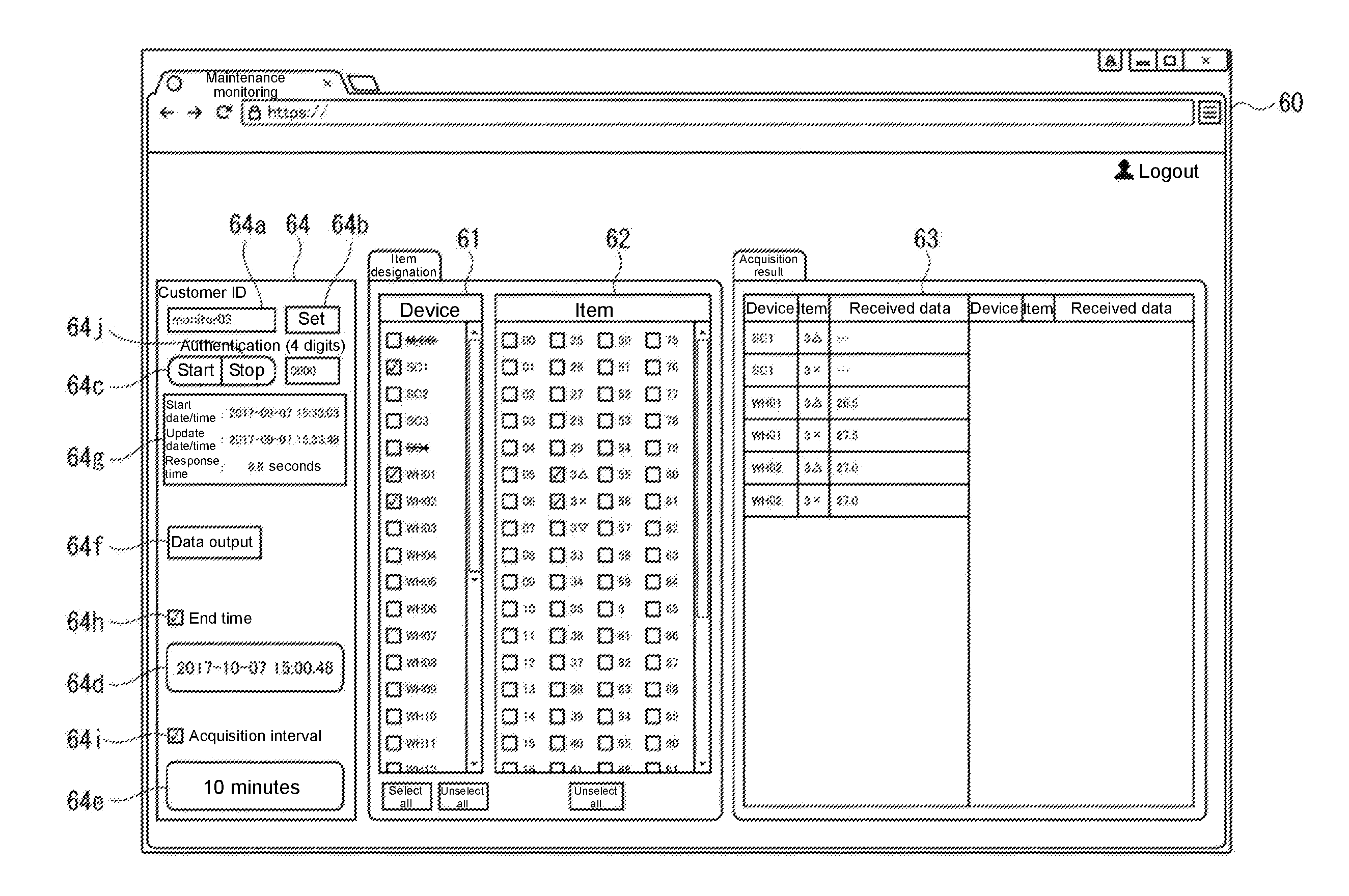
[0038] FIG. 2 is a diagram showing an example of a maintenance monitoring screen displayed on the display device of the management device according to the present embodiment. The item display part 52 displays the maintenance monitoring screen 60 on the display device (the display part of the communication terminal 6, for example) connected to the management device 5. The maintenance monitoring screen 60 is mainly used by the service person of the water heater 1 and is displayed after logging in the remote monitoring system by accessing the URL of the management device 5 from a Web browser installed in the communication terminal 6 or by executing a dedicated application and inputting the user ID registered for each service person for authentication, for example. As described above, the item display part 52 displays multiple types of items related to the state of the water heater 1 on the maintenance monitoring screen 60 to be selected.
[0039] The maintenance monitoring screen 60 includes a device selection screen 61, an item selection screen 62, a data display screen 63, and a system selection screen 64. The device selection screen 61 is a first sub screen for selecting a display target device for displaying item information among a plurality of water heaters WH1 to WH24 and a plurality of system controllers SC1 to SC3. As in the configuration of FIG. 1, when the relay device 2 is connected to the controller 1a of one water heater 1 not via the system controller, the device selection screen 61 may not be displayed or may be displayed as a blank.
[0040] The item selection screen 62 is a second sub screen for selecting one or a plurality of items from a plurality of items (100, for example). Here, identification numbers 00 to 99 are displayed as identifiers respectively corresponding to the 100 items, and the user can select one or a plurality of the identification numbers. That is, multiple types of items related to the device selected on the device selection screen 61 are displayed on the item selection screen 62 to be selected.
[0041] The data display screen 63 is a third sub screen for displaying information related to all the items selected by the item selection screen 62 for all the display target devices selected by the device selection screen 61.
[0042] The system selection screen 64 is a fourth sub screen for inputting or selecting the user information and the acquisition period and acquisition interval of the device state information, or for displaying data acquisition information.
[0043] When the user such as the service person inputs a customer ID (ID of the user, etc. of the water heater 1; monitor 03 in the example of FIG. 2) to a customer ID input box 64a of the system selection screen 64 and selects a set button 64b, the system configuration (the water heater and the system controller, for example) set corresponding to the customer ID is displayed on the device selection screen 61 to be selected. On the device selection screen 61, devices that are not connected cannot be selected.
[0044] In the case where a plurality of users (service persons) input the same customer
[0045] ID in an overlapping period and select the set button 64b, the operation on the maintenance monitoring screen 60 performed by the user who selects the set button 64b first may be set as a valid operation and the operations of other users may not be accepted. At this time, the management device 5 may display that another user is using the maintenance monitoring function with the same customer ID on the display parts of the communication terminals 6 of the other users. At this time, the predicted waiting time may be displayed as well. In addition, the maintenance monitoring screen 60 displayed on the communication terminal 6 of the user who can perform a valid operation on the maintenance monitoring screen 60 may be displayed on (shared with) the communication terminals 6 of the other users.
[0046] In the state where the user has selected the desired device on the device selection screen 61 and selected at least one item corresponding to the desired device state information on the item selection screen 62, when an information acquisition start button 64c on the system selection screen 64 is operated, the command transmission part 51 of the management device 5 generates a command for acquiring information corresponding to the at least one item that the user selects on the maintenance monitoring screen 60 and transmits it to the relay device 2.
[0047] In accordance with the command transmitted from the management device 5 (at the timing of receiving the command), the information acquisition part 21 of the relay device 2 acquires at least one piece of information (device state information) from the multiple types of information related to the corresponding device and transmits the acquired device state information to the management device 5. The item display part 52 of the management device 5 displays the acquired device state information on the data display screen 63.
[0048] The command transmission part 51 transmits the above command at a predetermined transmission interval in a predetermined transmission period. Therefore, the information acquisition part 21 acquires the corresponding device state information every time it receives the above command and transmits the same to the management device 5. A data acquisition status display part 64g of the system selection screen 64 displays data acquisition start date/time (command transmission start date/time) and update date/time (latest data acquisition date/time) of the set transmission period. The data acquisition status display part 64g also displays the response time from command transmission to data reception. The data acquisition status display part 64g may also display the end time.
[0049] After acquisition of the device state information starts, when an information acquisition stop button 64j of the system selection screen 64 is selected, the command transmission part 51 stops transmitting the command. In this case, the desired device state information acquired in the period from the start of acquisition of the device state information to the selection of the information acquisition stop button 64j is displayed on the data display screen 63.
[0050] In addition, the command transmission part 51 stops transmitting the above command when a predetermined transmission period ends (when the end time elapses). Thus, finally, the desired device state information acquired at every predetermined time interval in the predetermined period is displayed on the data display screen 63. In the example of FIG. 2, the data display screen 63 is configured to display the numerical values of the acquired device state information in a list, but the data display screen 63 may be configured to display a graph in addition to or instead of the list.
[0051] After the transmission period ends, the notification part 53 notifies the user that the transmission period has ended. The form of notification is not particularly limited. For example, the notification part 53 displays text such as "data acquisition completed" in the data acquisition status display part 64g of the system selection screen 64. In addition to or instead of the above, the notification part 53 may notify the user, for example, by sending a data acquisition completion mail to a predetermined mail address such as a mail address registered in advance corresponding to the user ID (ID of the service person). Through the notification, it is possible to notify the user of the acquisition of information with the end of the transmission period and to prevent causing inconvenience to the user even when the setting of the transmission period is changed.
[0052] The device state information transmitted to the management device 5 is stored in association with the customer ID as a data acquisition history in the storage part 5a for each series of data groups acquired in the set information acquisition period (the period from the transmission start time to the transmission end time of the command). In addition, when the user selects a data output button 64f of the system selection screen 64, it is also possible to output the acquired device state information in a predetermined data format (csv format, for example). Thus, for example, it is possible to save and use the acquired device state information in the communication terminal 6 of the user. In the present embodiment, the device state information that can be outputted is a series of data groups in the latest information acquisition period, but a series of data groups in a past information acquisition period may also be read out from a data acquisition history and outputted.
[0053] Here, the transmission period of the above command is configured so that the setting is changeable. Therefore, the system selection screen 64 has an end time setting button 64d for changing the setting of the transmission period (end time of acquisition of the information) of the above command. When the user selects the end time setting button 64d, an end time setting screen (a fifth sub screen) for setting the end time of the information acquisition period is displayed.
[0054] FIG. 3 is a diagram showing an example of the end time setting screen according to the present embodiment. The end time setting screen 65 may be configured as a screen (tab or window) different from the maintenance monitoring screen 60 or may be configured as a pull-down menu screen of the end time setting button 64d. In the example of FIG. 3, the end time setting screen 65 includes a date setting part 65a, a time setting part 65b, a date reset part 65c, and a set button 65d.
[0055] In the date setting part 65a, the desired end date is configured to be selectable. In FIG. 3, the date setting part 65a includes a calendar display part and is configured so that the desired end date can be selected from the calendar display part. When the date reset part 65c is selected, it is reset to a predetermined date (the date of the operation, for example) regardless of the date selected in the date setting part 65a.
[0056] In the time setting part 65b, the desired end time is configured to be selectable. In the example of FIG. 3, the hour, minute, and second are configured to be selectable independently. When the user selects the set button 65d after selection of the end time is completed, the command transmission part 51 sets the end time of the transmission period for transmitting the command to the time that has been selected. The set end time is stored in the storage part 5a. Also, after the set button 65d is selected, the end time setting screen 65 is closed and the maintenance monitoring screen 60 is displayed again. The set end time (end time) is displayed in the end time setting button 64d.
[0057] Further, the transmission interval for transmitting the above command is configured so that the setting is changeable. Therefore, the system selection screen 64 has an acquisition interval setting button 64e for changing the setting of the transmission interval (the acquisition interval of the device state information) of the above command. When the user selects the acquisition interval setting button 64e, the acquisition interval setting screen (a sixth sub screen) for setting the acquisition interval of the device state information is displayed.
[0058] FIG. 4 is a diagram showing an example of the acquisition interval setting screen according to the present embodiment. The acquisition interval setting screen 66 may be configured as a screen (tab or window) different from the maintenance monitoring screen 60 or may be configured as a pull-down menu screen of the acquisition interval setting button 64e. In the example of FIG. 4, the acquisition interval setting screen 66 includes a time setting part 66a, an automatic setting part 66b, and a set button 66c. In the example of FIG. 4, in the time setting part 66a, it is possible to select a predetermined acquisition interval in the units of hour, minute, and second. When the user selects the set button 66c after selection of the acquisition interval is completed, the command transmission part 51 sets the transmission interval for transmitting the command to the time interval that has been selected. After selection of the acquisition interval is completed, the acquisition interval setting screen 66 is closed and the maintenance monitoring screen 60 is displayed again. The set acquisition interval is displayed in the acquisition interval setting button 64e.
[0059] According to the above configuration, the command for acquiring information related to the water heater 1, which is a hot water utilizing facility, is sent from the management device 5 to the relay device 2 at the predetermined transmission interval in the predetermined transmission period, and accordingly the relay device 2 acquires the corresponding information from the water heater 1. At this time, the transmission period for transmitting the command is configured so that the setting is changeable. That is, the user such as the service person can set the acquisition period of the desired information to any period by setting the transmission period for transmitting the command according to the desired information. Thus, with the above configuration, it is possible to acquire various information related to the hot water utilizing facility remotely in an appropriate period.
[0060] Further, in the present embodiment, the acquisition interval of the desired information can be set to any interval according to the acquisition period of the desired information. In addition, in the present embodiment, the desired information can be designated easily by selecting multiple types of items displayed on the maintenance monitoring screen 60 through the item display part 52. Moreover, the above configuration can also be realized by adding a function to the management device 5 (by changing the operation program of the management device 5, for example) in the existing remote monitoring system. Therefore, even in the existing remote monitoring system, it is possible to easily realize the configuration that is capable of acquiring various information related to the hot water utilizing facility remotely in an appropriate period without changing the software such as the operation program of the relay device 2.
[0061] The above embodiment illustrates an example that the end time setting screen 65 for setting the end time is displayed based on the calendar so as to set the transmission period of the command, but in addition to or instead of the above, an end time (timer time) calculated from the start of acquisition may be set.
[0062] Further, in the present embodiment, regarding the transmission period of the command (the acquisition period of the device state information) and the transmission interval of the command (the acquisition interval of the device state information), the command transmission part 51 is configured to be capable of switching between a case where the user changes the setting as described above and a case where a predetermined value is used. More specifically, when the user selects the end time change check box 64h of the system selection screen 64 to display a check mark in the end time change check box 64h, the end time (set by the end time setting screen 65) displayed on the end time setting button 64d is valid. On the other hand, by not displaying the check mark in the end time change check box 64h, the end time displayed on the end time setting button 64d becomes invalid and the predetermined transmission period (within the 30 minutes from the start of information acquisition, for example) that has been stored in the storage part 5a becomes valid.
[0063] Likewise, when the user selects the acquisition interval change check box 64i of the system selection screen 64 to display a check mark in the acquisition interval change check box 64i, the acquisition interval (set by the acquisition interval setting screen 66) displayed on the acquisition interval setting button 64e is valid. On the other hand, by not displaying the check mark in the acquisition interval change check box 64i, the acquisition interval (transmission interval) displayed on the acquisition interval setting button 64e becomes invalid and the predetermined transmission interval (0.5 seconds, for example) that has been stored in the storage part 5a becomes valid.
[0064] The predetermined transmission period and transmission interval are set in advance to the times that are frequently used for multiple items. Therefore, it is possible to save the trouble of setting the transmission period and the transmission interval every time and to prevent causing inconvenience.
[0065] Moreover, on the system selection screen 64, it is possible to automatically set the range of the settable transmission interval according to the transmission period. More specifically, when the user selects the automatic setting part 66b of the acquisition interval setting screen 66, the command transmission part 51 reads the currently set end time (transmission period) and sets the transmission interval (acquisition interval) according to the read transmission period. For example, when the transmission period is one week or more and one month or less, the command transmission part 51 sets the transmission interval to be selectable from a range of one minute or more and several minutes or less. Alternatively, when the transmission period is one week or more and one month or less, the command transmission part 51 may automatically set the transmission interval to a predetermined value from a range of one minute or more and several minutes or less according to the transmission period.
[0066] Thus, for example, when the transmission period is long, the transmission interval is lengthened accordingly; and when the transmission period is short, the transmission interval is shortened accordingly. Therefore, for example, when the transmission period to be set is long, by lengthening the transmission interval accordingly, it is possible to prevent excessive communication traffic and to prevent an excessive data amount from being stored in the storage part 5a of the management device 5. In addition, when it is desired to see a local value change, by setting both the transmission period and the transmission interval short, it is possible to acquire a local value change at a pinpoint and to prevent the acquired information from becoming redundant.
[0067] In addition to or instead of providing the automatic setting part 66b on the acquisition interval setting screen 66, the same automatic setting part may be provided on the end time setting screen 65. In that case, the command transmission part 51 sets the range of the settable transmission period according to the transmission interval.
[0068] With the above description, many modifications or other embodiments of the disclosure will be apparent to those skilled in the art. Accordingly, the above description should only be construed as illustrative, and is provided for teaching those skilled in the art the embodiments of implementing the disclosure. Details of the structure and/or functions can be changed substantially without departing from the spirit of the disclosure.
[0069] For example, the above embodiment illustrates an example of the configuration (the maintenance monitoring screen 60) in which the transmission period and the transmission interval of the command for one or a plurality of items corresponding to the device state information can be set collectively, but the command transmission part 51 may also be configured such that the transmission period and/or the transmission interval for command transmission can be set for each item. Further, on the maintenance monitoring screen 60, candidates of the suitable transmission period and/or transmission interval may be displayed according to the item.
[0070] In addition, the management device 5 may be divided into a plurality of devices and the plurality of devices may be configured to cooperate with one another to function as the management device 5. For example, the storage part 5a of the management device 5 may be configured as a device different from a computer that performs various calculations. Furthermore, the remote monitoring system may be configured to perform various calculations of the management device 5 by a plurality of computers.
[0071] Moreover, a combustion heating water heater is illustrated as an example of the hot water utilizing facility, but it may also be water heaters of other heating types such as heat pump heating and electric heating. Further, the hot water utilizing facility is not limited to the water heater 1 and may be a device, such as a hot water filtration device, configured to communicate with the management device 5 via the relay device 2. In addition, the water heater 1 may be a hot water supply device having at least one of the functions such as hot water supply function, bath reheating function, and hot water heating function.
[0072] Furthermore, the above configuration of the disclosure can also be applied to a configuration in which the remote controller of the water heater 1 (the hot water utilizing facility) is connected to or integrated with the relay device 2. In the illustrated configuration, the remote monitoring system is provided with the wireless LAN router 3 that performs wireless communication with the relay device 2, but the router that communicates with the management device 5 may be connected to or integrated with the relay device 2. That is, the relay device 2 may be configured to communicate with the management device 5 (3G connection or 4G connection) directly via the communication network 4. In addition, a router connected to the relay device 2 in a wired manner may be used instead of the wireless LAN router 3.
INDUSTRIAL APPLICABILITY
[0073] The disclosure is useful as a remote monitoring system that is capable of acquiring various information related to a hot water utilizing facility remotely in an appropriate period, and a relay device used therefor.
* * * * *
D00000
D00001
D00002
D00003
XML
uspto.report is an independent third-party trademark research tool that is not affiliated, endorsed, or sponsored by the United States Patent and Trademark Office (USPTO) or any other governmental organization. The information provided by uspto.report is based on publicly available data at the time of writing and is intended for informational purposes only.
While we strive to provide accurate and up-to-date information, we do not guarantee the accuracy, completeness, reliability, or suitability of the information displayed on this site. The use of this site is at your own risk. Any reliance you place on such information is therefore strictly at your own risk.
All official trademark data, including owner information, should be verified by visiting the official USPTO website at www.uspto.gov. This site is not intended to replace professional legal advice and should not be used as a substitute for consulting with a legal professional who is knowledgeable about trademark law.