Blind Fastener With Frangible Nut
VOVAN; Terry ; et al.
U.S. patent application number 16/201919 was filed with the patent office on 2019-05-30 for blind fastener with frangible nut. This patent application is currently assigned to SPS Technologies, LLC. The applicant listed for this patent is SPS Technologies, LLC. Invention is credited to Brian HOFFARTH, Su HUYNH, Florentin POPESCU, Terry VOVAN.
| Application Number | 20190162222 16/201919 |
| Document ID | / |
| Family ID | 64734135 |
| Filed Date | 2019-05-30 |


View All Diagrams
| United States Patent Application | 20190162222 |
| Kind Code | A1 |
| VOVAN; Terry ; et al. | May 30, 2019 |
BLIND FASTENER WITH FRANGIBLE NUT
Abstract
A blind fastener for connecting a plurality of panels includes a core bolt and a core nut. The core nut surrounds the core bolt. The core nut includes a main body, a nut head, and a tool engagement section. The nut head has a larger outside diameter than the main body. The core nut defines a frangible portion between the nut head and the tool engagement section. The frangible portion is configured to allow the tool engagement section to break off from the nut head when a torque applied to the tool engagement section is greater than a threshold torque after the blind fastener is installed in the plurality of panels.
| Inventors: | VOVAN; Terry; (Upland, CA) ; HOFFARTH; Brian; (Penfield, NY) ; HUYNH; Su; (Jenkintown, PA) ; POPESCU; Florentin; (Jenkintown, PA) | ||||||||||
| Applicant: |
|
||||||||||
|---|---|---|---|---|---|---|---|---|---|---|---|
| Assignee: | SPS Technologies, LLC Jenkintown PA |
||||||||||
| Family ID: | 64734135 | ||||||||||
| Appl. No.: | 16/201919 | ||||||||||
| Filed: | November 27, 2018 |
Related U.S. Patent Documents
| Application Number | Filing Date | Patent Number | ||
|---|---|---|---|---|
| 62590915 | Nov 27, 2017 | |||
| 62631560 | Feb 16, 2018 | |||
| Current U.S. Class: | 1/1 |
| Current CPC Class: | B23P 19/062 20130101; F16B 19/1063 20130101; F16B 37/145 20130101; F16B 31/021 20130101; F16B 5/02 20130101; F16B 13/061 20130101; F16B 19/1072 20130101 |
| International Class: | F16B 31/02 20060101 F16B031/02 |
Claims
1. A blind fastener for connecting a plurality of panels, comprising: a core bolt; and a core nut surrounding the core bolt, the core nut including a main body, a nut head, and a tool engagement section, the nut head having a larger outside diameter than the main body, wherein the core nut defines a frangible portion between the nut head and the tool engagement section, the frangible portion configured to allow the tool engagement section to break off from the nut head when a torque applied to the tool engagement section is greater than a threshold torque after the blind fastener is installed in the plurality of panels.
2. The blind fastener according to claim 1, wherein the frangible portion is configured to break off from the nut head such that an end surface of the nut head is flush with or recessed from a front one of the plurality of panels.
3. The blind fastener according to claim 1, wherein a radially outward facing surface of the main body of the core nut includes a plurality of dimples.
4. The blind fastener according to claim 1, wherein the blind fastener consists of two pieces when in a pre-installed condition, the core bolt being a first one of the two pieces and the core nut being a second one of the two pieces.
5. The blind fastener according to claim 1, wherein the frangible portion includes a break-off groove that extends along an entire periphery of the core nut.
6. The blind fastener according to claim 5, wherein the nut head defines a first cylindrical surface and the tool engagement portion defines a second cylindrical surface, wherein the break-off groove is recessed radially inward from the first and second cylindrical surfaces.
7. The blind fastener according to claim 1, wherein the core nut defines a counter bore having an enlarged part and a threaded part, the enlarged part being formed in the tool engagement portion and having a larger inside diameter than the threaded part, wherein the threaded part is disposed in at least one of the nut head and an end of the main body proximal to the nut head.
8. The blind fastener according to claim 1, wherein the main body defines a counter bore having a smooth part and a threaded part, the smooth part having an inside diameter larger than the threaded part such that a nut stop shoulder is defined between the smooth part and the threaded part, wherein the core bolt defines a bolt stop shoulder that is configured to abut the nut stop shoulder when a frangible portion of the core bolt is aligned with or recessed from an outer surface of a front one of the plurality of panels.
9. The blind fastener according to claim 1, wherein the core nut further includes a sleeve coupled to an end of the main body that is distal to the nut head, wherein the core bolt includes a bolt head engaged with an end of the sleeve that is distal to the main body, and wherein the main body includes a ramp surface configured to slidingly engage an inner surface of the sleeve.
10. The blind fastener according to claim 9, wherein the bolt head includes a central recess facing axially outward from the core bolt.
11. The blind fastener according to claim 9, wherein the sleeve is coupled to the end of the main body by a second frangible section of the core nut.
12. The blind fastener according to claim 9, wherein the ramp surface includes a plurality of grooves.
13. The blind fastener according to claim 1, wherein the nut head defines a conical surface and an end surface, the conical surface being configured to abut a countersunk surface of a front panel of the plurality of panels, the end surface configured to be flush with or recessed from a forward surface of the front panel when the conical surface abuts the countersunk surface.
14. A blind fastener for connecting a plurality of panels, comprising: a core bolt including a first tool engagement section, a threaded section and a bolt head, the threaded section including a first frangible portion configured to break the threaded section when a torque applied to the first handling section exceeds a first threshold torque, the threaded section being axially between the first tool engagement section and the bolt head; and a core nut including a main body, a nut head, a second frangible portion, and a second tool engagement section, the second frangible portion frangibly coupling the second tool engagement section to the nut head and configured to break the second tool engagement section off from the nut head when a torque applied to the second tool engagement section exceeds a second threshold torque, the nut head being axially between the second frangible section and the main body, wherein at least one of the main body and the nut head defines internal threads configured to engage the threaded section of the core bolt, and the bolt head is configured to engage an end of the core nut that is opposite the nut head.
15. The blind fastener according to claim 14, wherein the main body includes a ramp section, a sleeve section, and a third frangible section that frangibly couples the sleeve section to the ramp section.
16. The blind fastener according to claim 14, wherein the core nut further includes a sleeve section and the main body includes a ramp surface configured to slidably engage an inner surface of the sleeve section.
17. The blind fastener according to claim 14, wherein the nut head defines a conical surface and an end surface, the conical surface being configured to abut a countersunk surface of a front panel of the plurality of panels, the end surface configured to be flush with or recessed from a forward surface of the front panel when the conical surface abuts the countersunk surface.
18. The blind fastener according to claim 16, wherein the main body defines a counter bore having a smooth part and a threaded part, the threaded part defining the internal threads, the smooth part having an inside diameter larger than a major diameter of the internal threads of the threaded part such that a nut stop shoulder is defined between the smooth part and the threaded part, wherein the core bolt defines a bolt stop shoulder that is configured to abut the nut stop shoulder when a frangible portion of the core bolt is aligned with or recessed from an outer surface of a front one of the plurality of panels.
19. An assembly comprising: a front panel defining a front surface; a rear panel defining a rear surface; a blind fastener inserted into holes of the front and rear panels for connecting the front and rear panels together, the blind fastener comprising: a core bolt received in the holes of the front and rear panels and defining a break-off notch and a bolt head; and a core nut surrounding the core bolt, the core nut including a main body, a nut head, a sleeve, and a tool engagement section, the main body extending within the holes of the front and rear panels, the nut head disposed in a counterbore or countersink of the hole of the front panel, the tool engagement section disposed outside the front and rear panels and adjacent to the front panel, the sleeve being coupled to an end of the main body that is opposite the nut head and disposed outside and adjacent to the rear panel, the sleeve being configured to be deformed by axial force imparted by the bolt head moving toward the panels, the core nut further defining a break-off groove that frangibly couples the tool engagement section to the nut head, wherein the break-off groove of the core nut and the break-off notch of the core bolt are flush with or recessed from the front surface of the front panel when the blind fastener is fully installed.
20. The assembly according to claim 19, wherein the nut head of the core nut includes an end surface that is flush with the front surface of the front panel.
Description
CROSS-REFERENCE TO RELATED APPLICATIONS
[0001] This application claims priority to and the benefit of U.S. Provisional Application 62/590,915 filed on Nov. 27, 2017. This application also claims priority to and the benefit of U.S. Provisional Application 62/631,560 filed on Feb. 16, 2018. This application is also related to co-pending application titled "Two-Piece Blind Fastener," concurrently filed herewith and commonly assigned with the present application. The disclosures of the above applications are incorporated herein by reference.
FIELD
[0002] The present disclosure relates generally to fasteners, and more particularly to blind fasteners having a core bolt and a sleeve around the core bolt for connecting panels from one side of the panels.
BACKGROUND
[0003] The statements in this section merely provide background information related to the present disclosure and may not constitute prior art.
[0004] A blind fastener is typically used to secure multiple panels together and to be installed from one side (i.e., a front side) of the panels. The blind fastener may include a core bolt and a sleeve surrounding the core bolt, which are inserted into a hole of the panels. A portion of the sleeve adjacent to a rear side of the panel may be deformed during installation of the fastener. The deformed portion of the sleeve provides a bearing surface to induce preload in the fastener such that the panels can be clamped together.
[0005] After the deformed portion of the sleeve is formed, the core bolt may be rotated to provide a preload to the fastener. When the fastener is completely installed, a front portion of the core bolt may break off. The break-off point of the typical core bolt cannot be controlled and rotation of the nut relative to the bolt typically needs to be controlled. In some circumstances it is advantageous to have the fully installed fastener be flush with panels for aesthetics and aerodynamic purposes. Typical fasteners need to be prepared for painting by post-installation grinding to be made flush with the panels when the break-off point is located outside the countersunk head of the sleeve.
[0006] It can be difficult to control rotation of both the bolt and the nut, while also ensuring a flush finished product, maximizing the speed of installation, and reducing cost per fastener. Furthermore, variations in grip length (i.e., the combined thickness of the panels at the fastener) can occur based on tolerances or design criteria. Accordingly, it is advantageous for the blind fastener to be able to adapt to variations in grip length without sacrificing strength of the joint. Moreover, the typical fastener does not include a torque control feature. When excessive torque is applied to the fastener, the sleeve of the fastener may flare out to form a tulip configuration, resulting in a defective installation.
[0007] These issues with the installation of blind fasteners are addressed by the present disclosure.
SUMMARY
[0008] In one form, a blind fastener for connecting a plurality of panels includes a core bolt and a core nut. The core nut surrounds the core bolt. The core nut includes a main body, a nut head, and a tool engagement section. The nut head has a larger outside diameter than the main body. The core nut defines a frangible portion between the nut head and the tool engagement section. The frangible portion is configured to allow the tool engagement section to break off from the nut head when a torque applied to the tool engagement section is greater than a threshold torque after the blind fastener is installed in the plurality of panels. In a variety of alternate forms of the present disclosure: the frangible portion is configured to break off from the nut head such that an end surface of the nut head is flush with or recessed from a front one of the plurality of panels; a radially outward facing surface of the main body of the core nut includes a plurality of dimples; the blind fastener consists of two pieces when in a pre-installed condition, the core bolt being a first one of the two pieces and the core nut being a second one of the two pieces; the frangible portion includes a break-off groove that extends along an entire periphery of the core nut; the nut head defines a first cylindrical surface and the tool engagement portion defines a second cylindrical surface, the break-off groove is recessed radially inward from the first and second cylindrical surfaces; the core nut defines a counter bore having an enlarged part and a threaded part, the enlarged part being formed in the tool engagement portion and having a larger inside diameter than the threaded part, wherein the threaded part is disposed in at least one of the nut head and an end of the main body proximal to the nut head; the main body defines a counter bore having a smooth part and a threaded part, the smooth part having an inside diameter larger than the threaded part such that a nut stop shoulder is defined between the smooth part and the threaded part, wherein the core bolt defines a bolt stop shoulder that is configured to abut the nut stop shoulder when a frangible portion of the core bolt is aligned with or recessed from an outer surface of a front one of the plurality of panels; the core nut further includes a sleeve coupled to an end of the main body that is distal to the nut head, wherein the core bolt includes a bolt head engaged with an end of the sleeve that is distal to the main body, and wherein the main body includes a ramp surface configured to slidingly engage an inner surface of the sleeve; the bolt head includes a central recess facing axially outward from the core bolt; the sleeve is coupled to the end of the main body by a second frangible section of the core nut; the ramp surface includes a plurality of grooves; the nut head defines a conical surface and an end surface, the conical surface being configured to abut a countersunk surface of a front panel of the plurality of panels, the end surface configured to be flush with or recessed from a forward surface of the front panel when the conical surface abuts the countersunk surface.
[0009] In another form, a blind fastener for connecting a plurality of panels includes a core bolt and a core nut. The core bolt includes a first tool engagement section, a threaded section and a bolt head. The threaded section includes a first frangible portion configured to break the threaded section when a torque applied to the first handling section exceeds a first threshold torque. The threaded section is axially between the first tool engagement section and the bolt head. The core nut includes a main body, a nut head, a second frangible portion, and a second tool engagement section. The second frangible portion frangibly couples the second tool engagement section to the nut head and is configured to break the second tool engagement section off from the nut head when a torque applied to the second tool engagement section exceeds a second threshold torque. The nut head is axially between the second frangible section and the main body. At least one of the main body and the nut head defines internal threads configured to engage the threaded section of the core bolt. The bolt head is configured to engage an end of the core nut that is opposite the nut head. In a variety of alternate forms of the present disclosure: the main body includes a ramp section, a sleeve section, and a third frangible section that frangibly couples the sleeve section to the ramp section; the core nut further includes a sleeve section and the main body includes a ramp surface configured to slidably engage an inner surface of the sleeve section; the nut head defines a conical surface and an end surface, the conical surface being configured to abut a countersunk surface of a front panel of the plurality of panels, the end surface configured to be flush with or recessed from a forward surface of the front panel when the conical surface abuts the countersunk surface; the main body defines a counter bore having a smooth part and a threaded part, the threaded part defining the internal threads, the smooth part having an inside diameter larger than a major diameter of the internal threads of the threaded part such that a nut stop shoulder is defined between the smooth part and the threaded part, wherein the core bolt defines a bolt stop shoulder that is configured to abut the nut stop shoulder when a frangible portion of the core bolt is aligned with or recessed from an outer surface of a front one of the plurality of panels.
[0010] In still another form, an assembly includes a front panel, a rear panel, and a blind fastener. The front panel defines a front surface. The rear panel defines a rear surface. The blind fastener is inserted into holes of the front and rear panels for connecting the front and rear panels together. The blind fastener includes a core bolt and a core nut. The core bolt is received in the holes of the front and rear panels and defines a break-off notch and a bolt head. The core nut surrounds the core bolt. The core nut includes a main body, a nut head, a sleeve, and a tool engagement section. The main body extends within the holes of the front and rear panels. The nut head is disposed in a counterbore or countersink of the hole of the front panel. The tool engagement section is disposed outside the front and rear panels and adjacent to the front panel. The sleeve is coupled to an end of the main body that is opposite the nut head and is disposed outside and adjacent to the rear panel. The sleeve is configured to be deformed by axial force imparted by the bolt head moving toward the panels. The core nut further defines a break-off groove that frangibly couples the tool engagement section to the nut head. The break-off groove of the core nut and the break-off notch of the core bolt are flush with or recessed from the front surface of the front panel when the blind fastener is fully installed. In one form of a variety of alternate forms of the present disclosure, the nut head of the core nut includes an end surface that is flush with the front surface of the front panel.
[0011] Further areas of applicability will become apparent from the description provided herein. It should be understood that the description and specific examples are intended for purposes of illustration only and are not intended to limit the scope of the present disclosure.
BRIEF DESCRIPTION OF THE DRAWINGS
[0012] The present disclosure will become more fully understood from the detailed description and the accompanying drawings, wherein:
[0013] FIG. 1 is a cross-sectional view of a blind fastener inserted through a countersunk hole of panels to be connected and constructed in accordance with the teachings of the present disclosure;
[0014] FIG. 2 is a perspective view of a blind fastener constructed in accordance with the teachings of the present disclosure;
[0015] FIG. 3 is a cutaway view of the blind fastener of FIG. 2;
[0016] FIG. 4 is a perspective view of a core nut of a blind fastener constructed in accordance with the teachings of the present disclosure;
[0017] FIG. 5 is another perspective view of the core nut of FIG. 4;
[0018] FIG. 6 is a side view of the core nut of FIG. 4;
[0019] FIG. 7 is a cross-sectional view of the core nut, taken along line A-A of FIG. 6;
[0020] FIG. 8 is a partial perspective view of the core nut of FIG. 4;
[0021] FIG. 9 is another partial perspective view of the core nut of FIG. 4;
[0022] FIG. 10 is a cross-sectional view of a blind fastener in an installed state before portions of a core bolt and a core nut break off;
[0023] FIG. 11 is an end view of the blind fastener of FIG. 10;
[0024] FIG. 12 is an enlarged view of portion B of FIG. 10;
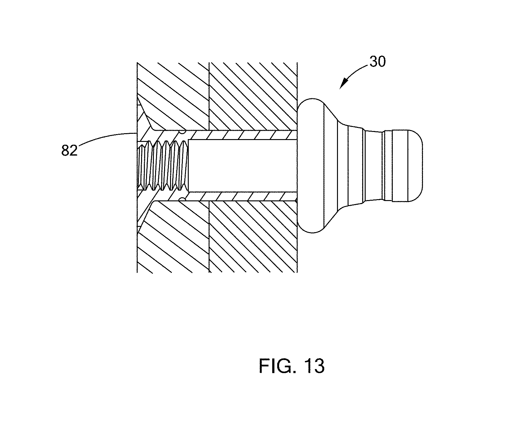
[0025] FIG. 13 is a cutaway view of a blind fastener in a final installed state after portions of a core bolt and a core nut break off;
[0026] FIG. 14 is a perspective view of a blind fastener after portions of a core nut and core bolt break off to form flush surfaces;
[0027] FIG. 15 is a cutaway view of the blinder fastener of FIG. 14;
[0028] FIG. 16 is a partial perspective view of the blinder fastener of FIG. 14, wherein a core bolt is removed to show a threaded part of the core nut;
[0029] FIG. 17 is a perspective view of a plurality blind fasteners installed in a panel;
[0030] FIG. 18 is a perspective view of a blind fastener constructed in accordance with a second form of the present disclosure;
[0031] FIG. 19 is another perspective view of a blind fastener of FIG. 18;
[0032] FIG. 20 is a perspective view of a blind fastener installed in panels and constructed in accordance with a second form of the present disclosure;
[0033] FIG. 21A is a cross-sectional view of a blind fastener constructed in accordance with a second form of the present disclosure;
[0034] FIG. 21B is an enlarged view of portion C of FIG. 21A;
[0035] FIG. 21C is a stress diagram of a portion of the fastener under a load/force;
[0036] FIG. 22A to 22E depict a series of breakage and deformation action of the blind fastener; and
[0037] FIG. 23 is a perspective view of a fastener in its initial installation stage and a fastener in its final installation stage.
[0038] Corresponding reference numerals indicate corresponding parts throughout the several views of the drawings.
DETAILED DESCRIPTION
[0039] The following description is merely exemplary in nature and is not intended to limit the present disclosure, application, or uses.
[0040] Referring to the FIGS. 1 to 3, a blind fastener 30 according to a first form of the present disclosure is configured to connect a plurality of panels including a front panel 1 and a rear panel 2, and is configured to be inserted into a countersunk hole 31 of the front and rear panels 1 and 2. The fastener 30 includes a core bolt 3, a core nut 5 surrounding a middle portion of the core bolt 3, and a sleeve 4 surrounding a rear portion of the core bolt 3. The rear portion of the core bolt 3 defines a smooth section 32, and the front portion and the middle portion of the core bolt 3 define a threaded section 34. A core bolt stop shoulder 10 is defined between the smooth section 32 and the threaded section 34 of the core bolt 3. An end of the front portion defines a tool engagement section configured to be gripped by a tool (not shown) so that the tool can impart torque on the core bolt 3 to rotate the core bolt 3. In the example provided, the tool engagement section of the core bolt 3 includes a plurality of flat surfaces 23.
[0041] The smooth section 32 of the core bolt 3 has an outer peripheral surface constituting a smooth rotational surface 12. The threaded section 34 of the core bolt 3 includes outer threads and a break-off notch 14 adjacent to the core bolt stop shoulder 10. The break-off notch 14 constitutes a weaker point at the core bolt 3 so that the core bolt 3 can be broken at the break-off notch 14 by applying a torsional force (for a thread type fastener) or a pulling force (for a pull type fastener) to the core bolt 3 after the fastener 30 is completely installed in the panels 1 and 2. In other words, the break-off notch 14 forms a frangible portion of the core bolt 3. In the example provided, the break-off notch 14 is disposed within the threaded section 34 such that the threads extend in both axial directions relative to the break-off notch 14 and the break-off notch 14 is configured so that it does not interfere with the threads of the threaded section 34 turning through mating threads even when the area with the break-off notch 14 is threaded through the mating threads.
[0042] The core bolt 3 further includes a core bolt head 9 at a rear end of the core bolt 3. The core bolt head 9 is disposed outside the sleeve 4 and defines a recess 8 that facilitates a removal process of the fastener 30 at the end of the product lifecycle by drilling out the fastener 30. The core bolt head 9 extends radially outward of the rear end of the sleeve 4 to overlap the rear end of the sleeve 4.
[0043] The sleeve 4 has a tubular configuration and includes an inner peripheral surface 11 constituting a smooth rotational surface 11 in contact with the smooth rotational surface 12 of the core bolt 3. The smooth rotational surface 12 of the core bolt 3 and the smooth rotational surface 11 of the sleeve 4 function as rotating bearing surfaces, which may be lubricated, when a front end 13 of the core bolt 3 is tightened or loosened to move the core bolt 3 relative to the core nut 5.
[0044] Referring to FIGS. 4 to 6, the core nut 5 has a tubular configuration and includes a main body 40, a nut head 46 and a second tool engagement section 42 having a larger outside diameter than the main body 40. The main body 40 includes a cylindrical portion 44 and a ramped portion 45. The second tool engagement section 42 includes a cylindrical portion 48 and a flange 50. A peripheral groove 52 is disposed between the nut head 46 and the second tool engagement section 42 to form a frangible portion of the core nut 5. The cylindrical portion 44 of the main body 40 further includes a plurality of dimples 58 at the front end. The ramped portion 45 includes an outward facing ramp surface 22 and a plurality of recess grooves 60 are formed on the ramp surface 22. The ramp surface 22 and the plurality of recess grooves 60 facilitate a slide-over action of the sleeve 4 during installation of the fastener 30, which will be described in more detail below. The second tool engagement section 42 is configured to be gripped by a tool during installation of the fastener 30 to prevent the core nut 5 from rotating when the core bolt 3 is screwed into or out of the core nut 5.
[0045] As clearly shown in FIG. 1, during installation of the fastener 30, the cylindrical portion 44 of the main body 40 and the nut head 46 are disposed in the countersunk hole 13 of the front and rear panels 1 and 3, with the nut head 46 in the countersunk portion of the hole 13 that is within the front panel 1. The second tool engagement section 42 including the cylindrical portion 48 and the flange 50 is disposed outside the front and rear panels 1 and 3. The peripheral groove 52 between the nut head 46 and the second tool engagement section 42 functions as a break-off groove to allow the second tool engagement section 42 to break off after the fastener 30 is completely installed, which will be described in more detail below.
[0046] Referring to FIGS. 7 to 9, the core nut 5 defines a counter bore 20 including a smooth part 72, a threaded part 74, and an enlarged part 76. The enlarged part 76 is formed in the tool engagement section 42 of the core nut 5 and has a larger inside diameter than the threaded part 74 and the smooth part 72. In the example provided, the threaded part 74 is positioned such that the internal threads extend axially through a portion of the nut head 46 and the cylindrical portion 44. The smooth part 72 has a larger inside diameter than the threaded part 74 such that a core nut stop shoulder 15 is defined between the smooth part 72 and the threaded part 74. The nut head 46 includes a conical surface 80 and an end surface 82 and is configured to be disposed in the countersunk hole 31 to retain the core nut 5 in one axial direction after the second tool engagement section 42 breaks off. In the example provided, the nut head 46 includes an outer cylindrical surface 83 (labeled in FIG. 12) adjacent to the conical surface 80. The groove 52 is recessed radially inward from the outer cylindrical surface 83 and the outer surface of the cylindrical portion 48 of the second tool engagement section 42.
[0047] Referring back to FIG. 1, during initial installation, the threaded part 74 of the core nut 5 is threadedly engaged to the threaded section 34 of the core bolt 3. The break-off notch 14 of the core bolt 3 is disposed away from the front surface 16 of the front panel 1, and the core bolt stop shoulder 10 is disposed away from the core nut stop shoulder 15 of the core nut 5. The end surface 82 of the nut head 46 of the core nut 5 and the break-off groove 52 of the core nut 5 are flush with the front surface 16 of the front panel 1.
[0048] Referring to FIGS. 1 and 10 to 12, by tightening the core bolt front end 13, the core bolt head 9 is moved towards the core nut 5 until the core bolt stop shoulder 10 comes to a positive stop and abuts against the core nut stop shoulder 15. Concurrently, the break-off notch 14 is moved to be flush with the front surface 16 of the front panel 1 and the end surface 82 of the nut head 46. The break-off groove 52 is also flush with the front surface 16 of the front panel 1. It is understood that the core bolt stop shoulder 10 and the core nut stop shoulder 15 are optional and do not have to be present in the blind fastener 30 to create flush surfaces in the blind fastener 30 after the blind faster is completely installed.
[0049] As the core bolt 3 is tightened and the core bolt head 9 is moved toward the core nut 5, the sleeve 4 is compressed and deformed by the core bolt head 9. The sleeve 4 expands and covers the ramp surface 22 of the core nut 5 and slides toward the rear surface of the rear panel 2. Radial core nut serrations 19 may be formed on the core nut 5 to prevent the sleeve 4 from freely rotating during the initial installation. Before complete installation of the fastener 30, the break-off notch 14 and the external threads of the core bolt 3 are disposed inside the counter bore 20 of the core nut 5 and are prevented against damage by any external force. The break-off notch 14 and the external threads of the core bolt 3 may be lubricated or sealants may be applied.
[0050] When the sleeve 4 is slid over the ramp surface 22 of the core nut 5, the sleeve 4 is deformed, forming a bulb portion 21. The bulb portion 21 may have a convex configuration depending on the total grip length of the panels 1 and 2. The size of the bulb portion 21 may be varied depending on the grip length, which is equal to the thickness of the panels to be connected. The recess grooves 60 formed on the ramp surface 22 of the core bolt 3 may facilitate the sleeve front to cave into the recess grooves 60 to avoid a defective tulip condition, i.e., the sleeve front flaring out. As shown in FIG. 1, the sleeve 4 may have a counter bore 17 having an enlarged hole adjacent to the core nut 5. The enlarged hole of the counter bore 17 also facilitates the slide-over action of the sleeve 4 over the ramp surface 22 of the core nut 5.
[0051] As clearly shown in FIG. 10 and with continued reference to FIGS. 1 and 7, an internal positive stop is provided between the core bolt stop shoulder 10 and the core nut stop shoulder 15. Therefore, the bulb portion 21, in a tensile linear stage, is not in a fully compressed position. The bulb portion 21 can provide a higher tensile preload in keeping the panels 1, 2 together in a high frequency of vibration. Moreover, the internal positive stop by the core bolt stop shoulder 10 and the core nut stop shoulder 15 allows the fastener 30 to reach a desired panel thickness, preferably an average distance between maximum and minimum panel thicknesses. This positive stop can also precisely regulate the break-off position of the core bolt 3 and the core nut 5 of the fastener 10, to ensure it would not exceed the tolerances of protrusion or recess of the mounting panel 1 or the countersunk head.
[0052] Referring to FIGS. 1, 7, and 13, after the fastener 30 is installed in the panels 1 and 3, by continuing to apply a torsional force on the core bolt 3, the threaded front portion of the core bolt 3 is broken at the break-off notch 14. An end surface of the core bolt 3 is formed and becomes flush with the front surface 16 of the panel 1. Also, by applying torsional force on the core nut 5, the second tool engagement section 42 breaks off at the break-off groove 52. The end surface 82 of the main body 40 is exposed and is flush with the front surface 16 of the front panel 1.
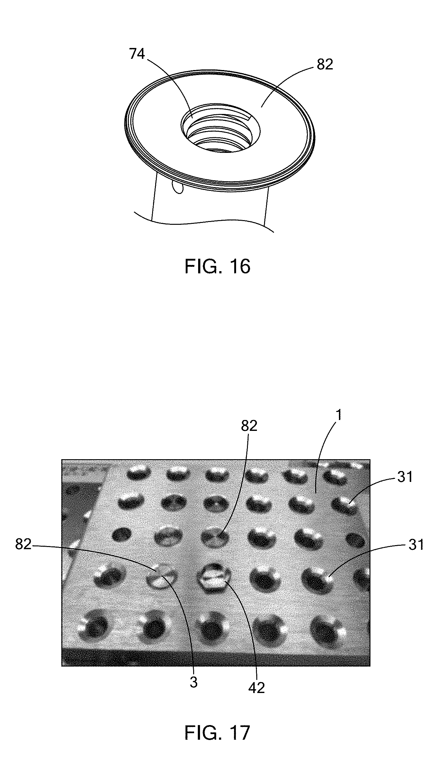
[0053] Referring to FIGS. 14 to 16, the fastener 30 is shown to be in a completely installed state with the second tool engagement section 42 of the core nut 5 and the front portion of the core bolt 3 broken off. The panels 1 and 3 being connected are not shown for clarity. As shown, the end surface 82 of the main body 40 becomes the outermost end of the fastener 30 in its completely installed state, and the end surface 82 is flush with a surface of the core bolt 3 that is formed after the front portion of core bolt 3 breaks off at the break-off notch 14. In FIG. 16, the core bolt 3 is removed to show the threaded part 74 of the core nut 5.
[0054] Referring to FIG. 17, a plurality of countersunk holes 31 are shown to be formed through a front panel 1. Fasteners are installed in some of the countersunk holes 31. After the front portions of the core bolts 3 and the second tool engagement section 42 of the core nuts 5 break off, flat end surfaces are formed on the core bolts 3 to be flush with the front surface 16 of the front panel 1. Also, the end surfaces 82 of the core nuts 5, which are preformed and configured to be flush with the front surface 16 of the front panel 1 during installation, are exposed. In one countersunk hole 31 of FIG. 17, the front portion of the core bolt 3 breaks off but the second tool engagement section 42 of the core nut 5 remains on the fastener 30, resulting in an uneven appearance.
[0055] Referring to FIGS. 18 to 20, a blind fastener 90 according to a second form of the present disclosure has a structure similar to the blind fastener 30 of the first form except that the sleeve and the core nut are integrally formed as a one-piece component. In the following, like elements are indicated by like reference numerals and the detailed description thereof is omitted herein for clarity.
[0056] More specifically, the blind fastener 90 includes a core bolt 3 and an outer member 92 surrounding the core bolt 3. The core bolt 3 includes a core bolt head 9 at a rear end. The core bolt 3 is inserted into the outer member 92 with the core bolt head 9 disposed outside the outer member 92 and abutting against a rear end of the outer member 92.
[0057] Referring to FIG. 21A, the outer member 92 includes a sleeve 96 and a nut 98 connected to the sleeve 96 at a breakable interface 100. The sleeve 96 and the nut 98 are integrally formed. The sleeve 96 is structurally similar to the sleeve 4 of the first form. The nut 98 is structurally similar to the core nut 5 of the first form. Therefore, the detailed description of the sleeve 96 and the nut 98 is omitted herein for clarity.
[0058] Referring to FIGS. 21A and 21B, when the core bolt 3 is rotated relative to the one-piece outer member 92 to screw the core bolt 3 out of the outer member 92 in a forward direction Y, a force is applied on the outer member 92 and causes the breakable interface 100 between the sleeve 96 and the nut 98 to break, thereby separating the sleeve 96 from the nut 98. The breakable interface 100 may be configured to break at a stress level of 20-30 in-lbs, though other configurations can be used. After the breakable interface 100 breaks, the blind fastener 90 is structurally similar to the blind fastener 30 of the first form. As the force continues to be applied on the core bolt 3, the sleeve 96 that is disposed between the nut 98 and the core bolt head 9 slides over the nut 98 and is compressed and deformed to form a bulb portion. After the breakable interface 100 breaks, the blind fastener 90 has the same operation as that of the blind fastener 30 and thus the detailed description thereof is omitted herein.
[0059] Referring to FIGS. 21A and 21C, a stress diagram of a part of the blind fastener 90 and the panels 1 and 2 is shown. Under the same load/force, the panels 1 and 2 and the nut 98 of the outer member 92 have the lowest stress, whereas the sleeve 96 of the outer member 92 has the highest stress. The core bolt 2 has a stress level between the nut 98 and the sleeve 96 of the outer member 92 under the same load/force. Therefore, using the blind fastener 90 of the present disclosure, the panels 1 and 2 will not be undesirably deformed by excessive force because the core bolt 3 will break before the panels 1 and 2 are deformed. On the other hand, the sleeve 96 of the outer member 92 has the highest stress under the same load/force and is first to be deformed, making the blind fastener 90 relatively easily installed in the panels 1 and 2.
[0060] Referring to FIGS. 22A to 22E, a series of breakage and deformation actions of the blind fastener 90 caused by a torsional force applied to the core bolt 3 are described. FIG. 22A shows the position of the outer member 92 relative to the core bolt 3 during initial installation, where the sleeve 96 remains connected to the nut 98 of the outer member 92. The sleeve 96 includes a front end 102 and a rear end 104. The panels 1 and 2 may be made of aluminum. The core bolt 3 may be made of A286 stainless steel and can withstand a stress of 177-196 ksi. The different portions of the outer member 92, due to its varied thickness, can withstand different stress. The front end 102 of the sleeve 96 of the outer member 92 can withstand a stress of 75-78 ksi. The rear end 104 of the sleeve 96 of the outer member 92 can withstand a stress of 130-140 ksi. The nut 98 of the outer member 92 can withstand a stress of 177-196 ksi.
[0061] FIG. 22B shows the breakable interface 100 between the sleeve 96 and the nut 98 is the first break point to break during installation of the blind fastener 90, causing the sleeve 96 to be separated from the nut 98. The breakable interface 100 can withstand a stress of 20-30 in-lbs.
[0062] Referring to FIG. 22C, after the sleeve 96 is separated from the nut 98, the sleeve 96, which is disposed between the core bolt head 9 and the nut 98, is compressed therebetween as the core bolt 3 (and consequently the core bolt head 9) continues to move in the forward direction Y. As a result, a bulb portion is created in the sleeve 96.
[0063] Referring to FIG. 22D, as the core bolt 3 continues to be moved in the forward direction Y, the sleeve 96 slides over the nut 98 and the core bolt stop shoulder 10 is moved toward the stop shoulder 15 of the nut 98 until the two stop shoulders 10 and 15 contact each other. After the stop shoulder 10 of the core bolt 3 abuts against the stop shoulder 15 of the nut 98, continuing application of force will cause the core bolt 3 to break at the break-off notch 14, which is configured to break at a stress level of 40-45 in-lbs. It is understood that the stop shoulders 10 and 15 do not have to be present to make the core bolt 3 breaks at the break-off notch 14.
[0064] Referring to FIG. 22E, after the front portion of the core bolt 3 breaks off at the break-off notch 14, a second tool engagement section 42 of the nut 98 may break off at the break-off groove 52, which is configured to break at a stress level of 75-95 in-lbs.
[0065] Therefore, the blind fastener 90 of the second form may initially be a two-piece blind fastener that breaks at three different break points at different stages of installation and results in three separate pieces holding the panels 1 and 2 together. During initial installation, the sleeve 96 is separated from the nut 98 of the outer member 92 at the breakable interface 100 at a stress level of 20-30 in-lbs. After the sleeve 96 is deformed to have a bulb portion and the first panel 1 and the second panel 2 are clamped between the second tool engagement section 42 of the nut 98 and the bulb portion of the sleeve 96, the front portion of the core bolt 3 can break off at a stress level of 40-45 in-lbs, creating a flush surface 108 at the core bolt 3. Thereafter, the second tool engagement section 42 of the nut 98 can break at the break-off groove at a stress level of 75-90 in-lbs, thereby exposing the end surface 82 of the nut 98, which is another flush surface created by blind fastener 90.
[0066] Referring to FIG. 23, the blind fastener 90 on the right hand side is shown to be in its initial installation position where the sleeve 96 has yet to be deformed to form a bulb portion, whereas the blind fastener 90 on the left hand side is shown to be in its final installation position where the front portion of the core bolt 3 breaks off at the break-off notch 14 to form a flush surface 108 on the core bolt 3 and the second tool engagement section 42 of the nut 98 breaks off at the break-off groove 52 to form a flush surface 82 on the nut 98 of the outer member 92.
[0067] A typical fastener (not shown) may result in a break-off end being disposed inside the countersunk end of the core nut 5 or protruding outside the countersunk end of the core nut 5. Therefore, the secondary work to grind, shave, sand and fill in the front side of the fastener is typically required. This process requires a lot of labor time and costs, thereby increasing manufacturing costs, which is particularly significant in the aerospace industry where approximately 8,000 to 10,000 fasteners are used in each commercial aircraft.
[0068] In contrast, the fastener of the present disclosure is configured to create a flush surface with the front surface of the front panel after the blind fastener is completely installed. Therefore, the fasteners 30, 90 of the present disclosure can shorten the manufacturing time and reduce the manufacturing costs since no secondary work is required to treat the front surface of the fastener.
[0069] The fastener of the present disclosure also provides an aesthetic flush mounting and optimizes aerodynamic appearance. The fastener of the present disclosure provides a higher preload (compression pressure of the sandwiched mounting panels) with a minimum 50% of the tensile strength. Current blind fasteners on the market are fully compressed/deformed, which offers less preload value. Higher preload values are significantly beneficial in handling the high frequency vibrations of aircraft, in both threaded-type blind fasteners and pull-type blind rivets. The fastener of the present disclosure prevents over torque/pulling that creates a lower preload value, and defective installation due to a tulip configuration.
[0070] It should be noted that the disclosure is not limited to the form described and illustrated as examples. A large variety of modifications have been described and more are part of the knowledge of the person skilled in the art. These and further modifications as well as any replacement by technical equivalents may be added to the description and figures, without leaving the scope of the protection of the disclosure and of the present patent.
[0071] As used herein, the phrase at least one of A, B, and C should be construed to mean a logical (A OR B OR C), using a non-exclusive logical OR, and should not be construed to mean "at least one of A, at least one of B, and at least one of C.
[0072] Unless otherwise expressly indicated, all numerical values indicating mechanical/thermal properties, compositional percentages, dimensions and/or tolerances, or other characteristics are to be understood as modified by the word "about" or "approximately" in describing the scope of the present disclosure. This modification is desired for various reasons including industrial practice, manufacturing technology, and testing capability.
[0073] The terminology used herein is for the purpose of describing particular example forms only and is not intended to be limiting. The singular forms "a," "an," and "the" may be intended to include the plural forms as well, unless the context clearly indicates otherwise. The terms "including," and "having," are inclusive and therefore specify the presence of stated features, integers, steps, operations, elements, and/or components, but do not preclude the presence or addition of one or more other features, integers, steps, operations, elements, components, and/or groups thereof. The method steps, processes, and operations described herein are not to be construed as necessarily requiring their performance in the particular order discussed or illustrated, unless specifically identified as an order of performance. It is also to be understood that additional or alternative steps may be employed.
[0074] The description of the disclosure is merely exemplary in nature and, thus, examples that do not depart from the substance of the disclosure are intended to be within the scope of the disclosure. Such examples are not to be regarded as a departure from the spirit and scope of the disclosure. The broad teachings of the disclosure can be implemented in a variety of forms. Therefore, while this disclosure includes particular examples, the true scope of the disclosure should not be so limited since other modifications will become apparent upon a study of the drawings, the specification, and the following claims.
* * * * *
D00000
D00001
D00002
D00003
D00004
D00005
D00006
D00007
D00008
D00009
D00010
D00011
D00012

D00013

D00014

XML
uspto.report is an independent third-party trademark research tool that is not affiliated, endorsed, or sponsored by the United States Patent and Trademark Office (USPTO) or any other governmental organization. The information provided by uspto.report is based on publicly available data at the time of writing and is intended for informational purposes only.
While we strive to provide accurate and up-to-date information, we do not guarantee the accuracy, completeness, reliability, or suitability of the information displayed on this site. The use of this site is at your own risk. Any reliance you place on such information is therefore strictly at your own risk.
All official trademark data, including owner information, should be verified by visiting the official USPTO website at www.uspto.gov. This site is not intended to replace professional legal advice and should not be used as a substitute for consulting with a legal professional who is knowledgeable about trademark law.