Tensioning Cylinder Device
KLOFT; Peter ; et al.
U.S. patent application number 16/316704 was filed with the patent office on 2019-05-30 for tensioning cylinder device. The applicant listed for this patent is HYDAC TECHNOLOGY GMBH. Invention is credited to Herbert BALTES, Peter KLOFT.
| Application Number | 20190162209 16/316704 |
| Document ID | / |
| Family ID | 59313187 |
| Filed Date | 2019-05-30 |


| United States Patent Application | 20190162209 |
| Kind Code | A1 |
| KLOFT; Peter ; et al. | May 30, 2019 |
TENSIONING CYLINDER DEVICE
Abstract
The invention relates to a tensioning cylinder device, comprising a housing (2) and and at least partly longitudinally movable piston-rod unit (30, 34) arranged therein, and comprising a compensating element in the form of a bellows body (18) having bellows folds, which is longitudinally variable and has a media-carrying connection to a compressible medium accommodated in a medium chamber (12) in the housing (2).
| Inventors: | KLOFT; Peter; (Ransbach-Baumbach, DE) ; BALTES; Herbert; (Losheim, DE) | ||||||||||
| Applicant: |
|
||||||||||
|---|---|---|---|---|---|---|---|---|---|---|---|
| Family ID: | 59313187 | ||||||||||
| Appl. No.: | 16/316704 | ||||||||||
| Filed: | June 29, 2017 | ||||||||||
| PCT Filed: | June 29, 2017 | ||||||||||
| PCT NO: | PCT/EP2017/000775 | ||||||||||
| 371 Date: | January 10, 2019 |
| Current U.S. Class: | 1/1 |
| Current CPC Class: | F15B 15/1476 20130101; F15B 1/103 20130101; B23Q 3/082 20130101; F15B 2201/205 20130101; F16L 37/62 20130101; B23Q 3/08 20130101; B23Q 2703/04 20130101; F15B 2201/3153 20130101 |
| International Class: | F15B 15/14 20060101 F15B015/14; F15B 1/10 20060101 F15B001/10; B23Q 3/08 20060101 B23Q003/08; F16L 37/62 20060101 F16L037/62 |
Foreign Application Data
| Date | Code | Application Number |
|---|---|---|
| Jul 20, 2016 | DE | 10 2016 008 882.6 |
Claims
1. A tensioning cylinder device, having a housing (2) and a piston-rod unit (30, 34) at least partially displaceable longitudinally therein and having a compensating element in the form of a bellows body (18) having bellows folds, which bellows body is variable in length and in media-conveying connection with a compressible medium in a media chamber (12) in the housing (2).
2. The tensioning cylinder device according to claim 1, characterized in that the bellows body (18) in the housing (2) is clamped between an attachment point (22) located at the latter and a movable guide plate (26), which separates a second media chamber (42) holding incompressible medium from the media chamber (12) holding the compressible medium.
3. The tensioning cylinder device according to claim 1, characterized in that the outside of the bellows folds of the bellows body (18) is guided along the inside of the cylindrical housing (2).
4. The tensioning cylinder device according to claim 1, characterized in that within the housing (2) the piston rod unit (30, 34) separates the second media chamber (42) holding the incompressible medium from a further, third media chamber (44) holding a likewise incompressible medium.
5. The tensioning cylinder device according to claim 1, characterized in that the pressure existing in the media chamber (12) holding the compressible medium is transmitted to the piston-rod unit (30, 34) via the guide plate (26) of the bellows body (18) and via the second media chamber (42) holding the incompressible medium.
6. The tensioning cylinder device according to claim 1, characterized in that the further, third media chamber (44) is provided with a control port (46), which, pressurized with a fluid pressure, which is greater than the pressure of the compressible medium, permits the retraction of the piston rod unit (30, 34) in the direction of the guide plate (26).
7. The tensioning cylinder device according to claim 1, characterized in that in the fully extended state of the piston-rod unit (30, 34), an end-side piston surface rests against a residual volume of incompressible medium in the third media chamber (44).
8. The tensioning cylinder device according to claim 1, characterized in that the rod (34) of the piston-rod unit (30, 34) has an outwardly closable passage opening (40), which opens into the second media chamber (42) and which serves to accommodate the incompressible medium.
9. The tensioning cylinder device according to claim 1, characterized in that the housing (2) is cup-shaped having a closing head (6), which has the control port (46).
10. The tensioning cylinder device according to claim 1, characterized in that the attachment point of the bellows body (18) is formed from a securing ring (22), which stationarily engages with a recess (24) in the inner wall of the housing (2).
11. A collet, in particular for attaching two flange halves to each other using a pre-determinable tensioning force, which is maintained over a long period of use, having two tensioning jaws (58, 60, 64), which in particular limit a tensioning space (62) for receiving the two flange halves (58, 50), wherein one tensioning jaw (60, 64) can be moved towards and away from the other tensioning jaw (58) characterized in that at least one tensioning jaw (60, 64) can be moved by means of a tensioning cylinder device (2, 34) according to claim 1.
Description
[0001] The invention relates to a tensioning cylinder device, comprising a housing and an at least partially longitudinally displaceable piston-rod unit arranged therein. Furthermore, the invention relates to a collet, in particular for attaching two flange halves to each other.
[0002] Tensioning cylinder devices having a longitudinally movable piston-rod unit for generating an actuating force are state of the art. Such cylinder devices are often used as holding cylinders or as actuating cylinders, for example in power plants. In particular in applications as holding cylinders, it must be ensured that the generated tensioning force does not decrease over a long period of time. This requirement must be met especially in off-shore applications of tensioning cylinder devices. In this case, tensioning cylinder devices are used to keep flange halves together using a predetermined force, for example on underwater housings or pipelines or the like. Several tensioning cylinder devices are frequently arranged at the periphery of flanges in such systems.
[0003] For example, DE 10 2011 009 276 A1 has already proposed a device for transmitting a hydraulic working pressure in a pressure fluid for pressure actuation of hydraulic devices of deep-sea installations, wherein a first pressure chamber for the pressure fluid, a movable piston arrangement for changing the volume of this pressure chamber and at least a second pressure chamber are present in a cylinder arrangement, which second pressure chamber can be pressurized with the ambient pressure of the deep sea to generate a movement of the piston assembly generating a working pressure in the first pressure chamber. In this known solution, the working pressure in the cylinder assembly is not generated or transmitted by means of seawater acting directly on the piston assembly but a pressure accumulator is located upstream of the cylinder assembly, from which pressure accumulator an actuating fluid, which is at the deep sea pressure, can be fed to the cylinder assembly, in order to generate the required working pressure.
[0004] Based on this prior art, the invention addresses the problem of providing a tensioning cylinder device, by means of which a permanent operating force can be safely generated over long periods of operation.
[0005] According to the invention this problem is solved by a tensioning cylinder device having the features of claim 1 in its entirety.
[0006] Because a media chamber holding a compressible medium, such as a working gas, such as N.sub.2, is provided in the housing, which is in connection with a variable-length bellows body, a compressed gas volume is available as energy storage. As this is enclosed by a variable-length bellows body, preferably in the form of a metal bellows, and thus hermetically closed, reliability over long periods of time is ensured. The tensioning cylinder device according to the invention is therefore particularly suitable for underwater use. As the variable length bellows body can serve as a transmission element for the operating force on the piston-rod unit generated by the energy storage, the tensioning cylinder device according to the invention is also characterized by a simple, compact and reliable construction.
[0007] In advantageous exemplary embodiments the bellows body is clamped in the housing between an attachment point located there and a movable guide plate, which separates a second media chamber holding an incompressible medium from the media chamber holding the compressible medium. The guide plate may be welded to the adjacent last bellows fold as the end closure plate of the bellows body. A commercial metal bellows closed on at least one side can also be used, however.
[0008] Advantageously, the bellows body may be dimensioned such that the outside of its bellows folds is guided along the inside of the cylindrical housing, which increases the stability against buckling.
[0009] With particular advantage, the arrangement can be made such that within the housing the piston-rod unit separates the second media chamber holding the incompressible medium from a further, third media chamber holding a likewise incompressible medium. In this way, a compact, tradable physical unit is created.
[0010] In this arrangement, the pressure existing in the first media chamber holding the compressible medium acts on the piston-rod unit via the guide plate of the bellows body and via the second media chamber holding the incompressible medium. The incompressible medium, which forms the intermediate transformer for actuating forces effective between the guide plate and piston rod unit in the second media chamber, may be a highly viscous oil, the viscosity of which forms a kind of damping pad between the guide plate and the adjacent end face of the piston-rod.
[0011] The further, third media chamber can be provided with a control port, which, pressurized with a fluid pressure that is greater than the pressure of the compressible medium, permits the retraction of the piston-rod unit in the direction of the guide plate.
[0012] The pressure supply by means of the control port can be designed such that an end-side piston surface is supported on a residual volume of incompressible medium in the third media chamber in the fully extended state of the piston-rod unit. In the fully extended state, a damping fluid cushion is therefore present also between this end face of the piston and the facing wall of the housing delimiting the third media chamber, which aids in preventing the direct contact of metallic surfaces.
[0013] In advantageous embodiments, the rod of the piston-rod unit has an outwardly closable passage opening, which opens into the second media chamber and which serves to receive the incompressible medium, which, as mentioned above, is preferably a highly viscous oil.
[0014] The housing may be cup-shaped, having a closing head having the control port. The rod of the piston-rod assembly may extend outwardly through a central bore in the closing head, wherein sealing members located within the drilled hole form the seal of the third media chamber located on the rod side of the piston.
[0015] The attachment point for the bellows body can be formed in an advantageous manner from a securing ring, which stationarily engages with a recess in the inner wall of the housing.
[0016] Subject matter of the invention is according to claim 11 also a collet, in particular for attaching two flange halves to each other using a pre-determinable tensioning force, which is maintained over a long period of use, having two tensioning jaws, which in particular limit a tensioning space for receiving the two flange halves, wherein one tensioning jaw can be moved towards and away from the other jaw and wherein the collet is characterized in that at least one tensioning jaw can be moved by means of a tensioning cylinder device according to one of the claims 1 to 10.
[0017] The invention is explained in detail with reference to the drawings below.
[0018] In the drawings:
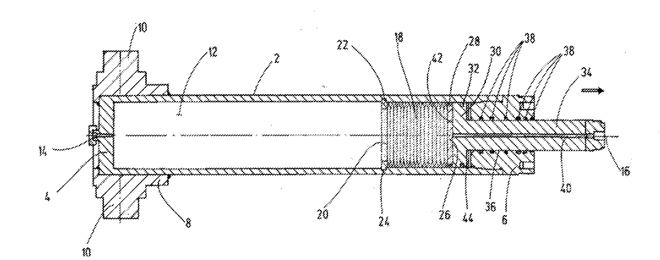
[0019] FIG. 1 shows a longitudinal section of an exemplary embodiment of the tensioning cylinder device according to the invention, wherein the tensioning state is shown, in a representation reduced by approx. factor 61/2 in comparison to the size of a practical embodiment;
[0020] FIG. 2 shows a longitudinal section of the exemplary embodiment shown, rotated by 90.degree. with respect to FIG. 1, wherein the release state is shown; and
[0021] FIG. 3 shows a mainly schematically drawn longitudinal section of the tensioning cylinder device according to the invention actuatable by means of the collet.
[0022] The exemplary embodiment of the tensioning cylinder device shown has a circular cylindrical housing 2, which is closed by a bottom 4 to form a cup at the end on the left in FIGS. 1 and 2. A screwed-in closing head 6 is provided as a housing closure at the opposite end of the housing 2. In the area of the bottom 4, the housing 2 is welded to a holding body 8 having fasteners 10 projecting on two opposite sides as an attachment for installation in a relevant system.
[0023] The part of the housing 2 adjacent to the bottom 4 serves as a first media chamber 12, which can be filled with a highly pressurized, for instance at 250 to 300 bar, working gas, such as N.sub.2, via a filling port 14, which is arranged at the bottom 4 coaxially to the housing longitudinal axis 16. The end of the media chamber 12 opposite the bottom 4 is formed by a bellows body 18, which is formed as a metallic bellows and the outside of its bellows folds is guided longitudinally variably on the inner wall of the housing 2. The open end of the bellows body 18 facing the bottom 4 is attached to an attachment point of the housing 2. It is designed in the example shown by a securing ring 22, to which the last bellows fold of the bellows body 18 is welded, or only rests against, and which, in the manner of a snap ring, sits in a recessed indentation 24 in the inner wall of the housing 2. At the other end the bellows body 18 is closed by a guide plate 26 welded to the adjacent last fold of the bellows, or even only resting against the latter, which is longitudinally movable in the housing 2 and guided on the housing inner wall by a guide 28.
[0024] As shown in FIGS. 1 and 2, the securing ring 22 is fixed to the inner wall of the housing 2 in a position, in which the length of the first media chamber 12 containing the pressurized gas is substantially larger than the remaining length of the housing 2 in the housing 2 from the attachment point on the securing ring 22 to the outer end of the closing head 6. In the example shown in FIGS. 1 and 2, the securing ring 22 is disposed at a position where the distance from the bottom 4 is about 1.6 times the distance from the outer end of the closing head 6. In the housing section between the guide plate 26 and the closing head 6, a piston-rod unit is arranged, the piston 30 of which is longitudinally movable in the housing 2 and sealed by a piston seal 32. The rod 34 of the piston rod unit extends from side of the piston 30 facing the closing head 6 through a through bore 36 formed in the closing head 6 coaxial to the cylinder axis 16 to the outside, wherein sealing elements 38 form the seal between the rod 34 and the closing head 6.
[0025] The rod 34 has a channel 40 coaxial to the axis 16, which extends from the flat piston side of the piston 30 facing the guide plate 26 to the outer free end of the rod 34. The channel 40 can be used to fill a highly viscous oil as an incompressible medium into a second media chamber 42, which is located between the flat piston side of the piston 30 and the guide plate 26. The annular space surrounding the rod side of the piston 30 and extending to the facing end of the closing head 6 forms a third media chamber 44 for an incompressible medium. The incompressible medium, such as hydraulic oil, which is supplied to this third media chamber 44 via a control port 46 (FIG. 2) of the closing head 6 and via a control channel 48, forms the control medium for a release operation of the tensioning cylinder device.
[0026] FIG. 1 shows the tensioning state of the device, in which no effective control pressure exists in the third media chamber 44, which would counteract the gas pressure existing in the first media chamber 12. The pressure of the first media chamber 12 functioning as an energy storage has therefore extended the bellows body 18, wherein the guide plate 26 acts upon the piston 30 with displacement force, such that the rod side of the piston 30 has moved against the closing head 6 and the rod 34 is extended into the tensioning position. In doing so, the viscous oil acts as a pad cushioning the metallic contact in the gap-like second media chamber 42 between the guide plate 26 and piston 30. A residual volume of hydraulic oil serving as a control medium in the third media chamber 44 again acts as a cushioning pad in the third media chamber 44 against direct mechanical contact between the rear side of the piston 30 and the closing head 6.
[0027] FIG. 2 shows the released state when the control pressure is supplied via the control port 46. For the smaller rod-side pressure-effective piston surface in the media chamber 44, the control pressure is supplied at a far higher pressure level in relation to the working gas pressure existing in the first media chamber 12, for instance at a release oil pressure of 700 bar, for a gas pressure of 250 up to 300 bar existing in the energy storage (media chamber 12).
[0028] The highly viscous oil introduced via the channel 40 in the media chamber 42 that establishes the power coupling between the bellows guide plate 26 and the bottom of the piston 30 may preferably be provided at a correspondingly larger amount to compensate for possible losses through the individual sealing system. Furthermore, the pressure at the pressure port 46 may be permanently monitored by a pressure sensor (not shown). Upon detection of a pressure increase in the media chamber 44 in the tensioning state of the device, i.e. in the absence of the control pressure in the media chamber 44, a leak at the piston 30 can be detected, such that a scheduled maintenance can be performed including the replacement of sealing elements. Such monitoring is not possible for the tensioning devices in the prior art that use spring force.
[0029] FIG. 3 shows a simplified schematic representation of a collet 52 for fixating flange halves 54 and 56, drawn in a schematized manner, between two tensioning jaws 58 and 60, which define a tensioning space 62 for receiving the flange halves 54, 56. In doing so, the piston rod 34 of the tensioning cylinder device according to the invention forms a movable part of the tensioning jaw 60 in the form of a pressure piece 64, which is movable upon actuation by means of the tensioning cylinder device having a tensioning stroke of 100 mm shown in the example in FIGS. 1 and 2. The flange halves 54, 56 shown are solely held to each other in the fixed state by means of the tensioning jaws 58 and 60 of the collets 52 via the gas pressure in the first media chamber 12. As the metal bellows 18 is designed to be media-tight and the guide plate 26 sealed by the seal 28 is pressed against the high pressure oil volume of the media chamber 42 as shown in the pertinent FIG. 1, which oil volume also forms a kind of seal, gas losses are prevented and a long-lasting positive connection is achieved.
* * * * *
D00000
D00001
D00002
XML
uspto.report is an independent third-party trademark research tool that is not affiliated, endorsed, or sponsored by the United States Patent and Trademark Office (USPTO) or any other governmental organization. The information provided by uspto.report is based on publicly available data at the time of writing and is intended for informational purposes only.
While we strive to provide accurate and up-to-date information, we do not guarantee the accuracy, completeness, reliability, or suitability of the information displayed on this site. The use of this site is at your own risk. Any reliance you place on such information is therefore strictly at your own risk.
All official trademark data, including owner information, should be verified by visiting the official USPTO website at www.uspto.gov. This site is not intended to replace professional legal advice and should not be used as a substitute for consulting with a legal professional who is knowledgeable about trademark law.