Method For Detecting A Gas Amount
HUBER; Johannes ; et al.
U.S. patent application number 16/097768 was filed with the patent office on 2019-05-30 for method for detecting a gas amount. This patent application is currently assigned to GE Jenbacher GmbH & Co. OG. The applicant listed for this patent is GE JENBACHER GMBH & CO. OG. Invention is credited to Friedrich GRUBER, Johannes HUBER.
| Application Number | 20190162127 16/097768 |
| Document ID | / |
| Family ID | 58699153 |
| Filed Date | 2019-05-30 |
| United States Patent Application | 20190162127 |
| Kind Code | A1 |
| HUBER; Johannes ; et al. | May 30, 2019 |
METHOD FOR DETECTING A GAS AMOUNT
Abstract
A method for detecting the quantity of gas (m) which is supplied by means of a gas supply device to an antechamber of an internal combustion engine, whereby a targeted disturbance (.DELTA.u) of the gas quantity (m) supplied by the gas supply device is performed and a change (.DELTA.T) resulting from the target disturbance (.DELTA.u) in an exhaust gas temperature (T) of an exhaust gas generated in a combustion chamber connected to the antechamber is measured, whereby, by comparison with a target value of the change (.DELTA.Ttarget) of the exhaust gas temperature (T), the gas quantity (m) supplied by means of the gas supply device is deduced.
| Inventors: | HUBER; Johannes; (Hippach, AT) ; GRUBER; Friedrich; (Kramsach, AT) | ||||||||||
| Applicant: |
|
||||||||||
|---|---|---|---|---|---|---|---|---|---|---|---|
| Assignee: | GE Jenbacher GmbH & Co.
OG Jenbach AT |
||||||||||
| Family ID: | 58699153 | ||||||||||
| Appl. No.: | 16/097768 | ||||||||||
| Filed: | May 11, 2017 | ||||||||||
| PCT Filed: | May 11, 2017 | ||||||||||
| PCT NO: | PCT/EP2017/061292 | ||||||||||
| 371 Date: | October 31, 2018 |
| Current U.S. Class: | 1/1 |
| Current CPC Class: | Y02T 10/32 20130101; F02D 41/1446 20130101; F02D 41/2438 20130101; F02B 19/00 20130101; F02D 19/026 20130101; F02D 41/0027 20130101; F02D 41/0085 20130101; F02D 19/025 20130101; F02D 41/2467 20130101; F02D 19/024 20130101; Y02T 10/125 20130101; Y02T 10/30 20130101; Y02T 10/12 20130101 |
| International Class: | F02D 41/14 20060101 F02D041/14; F02D 41/00 20060101 F02D041/00; F02B 19/00 20060101 F02B019/00; F02D 19/02 20060101 F02D019/02; F02D 41/24 20060101 F02D041/24 |
Foreign Application Data
| Date | Code | Application Number |
|---|---|---|
| May 11, 2016 | AT | A 50434/2016 |
Claims
1. A method for detecting the quantity of gas (m) which is supplied by means of a gas supply device to an antechamber of an internal combustion engine, wherein a targeted disturbance (.DELTA.u) of the gas quantity (m) supplied by the gas supply device is performed and a change (.DELTA.T) resulting from the target disturbance (.DELTA.u) in an exhaust gas temperature (T) of an exhaust gas generated in a combustion chamber connected to the antechamber is measured, whereby, by comparison with a setpoint value of the change (.DELTA.Ttarget) of the exhaust gas temperature (T), the gas quantity (m) supplied by means of the gas supply device is deduced.
2. Method according to claim 1, whereby a gradient (dT/dm) of the exhaust gas temperature (T) with respect to the quantity of gas (m) is calculated taking account the change (.DELTA.m) in the quantity of gas (m) resulting from the targeted disturbance (.DELTA.u).
3. Method according to claim 2, whereby the calculated gradient (dT/dm) is compared with a target value of the gradient (dT/dmtarget) to make the deduction of the quantity of gas (m) supplied by means of the gas supply device.
4. Method for detecting the quantity of gas (m) which is supplied to at least two antechambers of an internal combustion engine by means of associated gas supply devices, wherein a targeted disturbance (.DELTA.u) of the supplied quantity of gas (m) is performed, and individually for combustion chambers connected to at least two antechambers, a change (.DELTA.T) of an exhaust gas temperature (T) of an exhaust gas resulting from the targeted disturbance (.DELTA.u) is measured, whereby, by comparing the resulting changes (.DELTA.T) in the exhaust gas temperatures (T), a difference between the quantities of gas (m) supplied by means of the different gas supply devices is deduced.
5. Method for equalization of the quantity of gas (m) which is supplied to at least two antechambers of an internal combustion engine by means of associated gas supply devices, wherein a targeted disturbance (.DELTA.u) of the supplied quantity of gas (m) is performed, and individually for combustion chambers connected to at least two antechambers, a change (.DELTA.T) of an exhaust gas temperature (T) of an exhaust gas resulting from the targeted disturbance (.DELTA.u) is measured, whereby, by comparing the resulting changes (.DELTA.T) in the exhaust gas temperatures (T), a difference is determined and an actuation of at least one of the at least two antechambers occurs such that the difference disappears.
6. Method according to claim 1, whereby the gas supply device(s) is or are formed as a channel or channels connected to an antechamber gas line, and the targeted disturbance (.DELTA.u) is performed--individually for each gas supply device--by changing a gas pressure in the antechamber gas line and/or by changing a quantity of air supplied to the antechamber gas line.
7. Method according to claim 1, whereby the gas supply device(s) is/are formed as an active antechamber gas valve(s) connected to an antechamber gas line, and the targeted disturbance (.DELTA.u) is performed by changing an opening duration and/or an opening time of the antechamber gas valve(s).
8. Method according to claim 1, whereby the targeted disturbance (.DELTA.u) is performed in the direction of a reduced quantity of gas (m).
9. An internal combustion engine with: at least one combustion chamber an antechamber connected to the at least one combustion chamber a gas supply device for the antechamber a control unit for controlling the gas supply device, a temperature sensor assigned to the at least one combustion chamber to measure an exhaust gas temperature (T) of an exhaust gas generated in the at least one combustion chamber, whereby the temperature sensor is connected to the control unit, wherein the control unit is designed to perform a targeted disturbance (.DELTA.u) of the quantity of gas (m) supplied by means of the gas supply device and by means of the temperature sensor, to measure a change (.DELTA.T) of the exhaust gas temperature (T) resulting from the targeted disturbance (.DELTA.u), and by comparison with a stored target value of the change (.DELTA.Ttarget) in the exhaust gas temperature (T), to deduce the quantity of gas (m) supplied by means of the gas supply device.
10. An internal combustion engine with: at least two combustion chambers at least two antechambers which are each connected to one of the at least two combustion chambers a gas supply device for each of the at least two antechambers a control unit for controlling the gas supply devices, at least two temperature sensors which are each assigned to one of the at least two combustion chambers, to measure an exhaust gas temperature (T) of an exhaust gas generated in the at least one combustion chamber, whereby each temperature sensor is connected to the control unit, wherein the control unit is designed to perform, for each of the at least two antechambers, a targeted disturbance (.DELTA.u) of the quantity of gas (m) supplied by means of each gas supply device, and by means of the assigned temperature sensor, to measure a change (.DELTA.T) of the exhaust gas temperature (T) of each combustion chamber resulting from the targeted disturbance (.DELTA.u), and by comparison of the resulting changes (.DELTA.T) of the exhaust gas temperatures (T), to calculate a difference.
11. An internal combustion engine according to claim 10, whereby the control unit is designed to actuate at least one of the at least two antechambers in such a way that the difference disappears.
12. An internal combustion engine according to claim 9, whereby the gas supply device(s) is/are designed as an antechamber gas line, and the control unit is designed to perform the targeted disturbance (.DELTA.u) by changing a gas pressure in the antechamber gas line and/or by changing a quantity of air supplied to the antechamber gas line.
13. An internal combustion engine according to claim 9, whereby the gas supply device(s) is/are designed as (an) active antechamber gas valve(s), and the control unit is designed to perform the targeted disturbance (.DELTA.u) by changing an opening duration and/or an opening time of the antechamber gas valve(s).
Description
TECHNOLOGY FIELD
[0001] This invention relates to a method for detecting the quantity of gas which is supplied by means of a gas supply device to an antechamber of an internal combustion engine, a method for detecting the quantity of gas which is supplied to at least two antechambers of an internal combustion engine by means of associated gas supply devices, a method for equalizing the quantity of gas which is supplied to at least two antechambers of an internal combustion engine by means of associated gas supply devices, and internal combustion engines.
BACKGROUND
[0002] In the prior art, it is not directly measured which quantity of gas is supplied to an antechamber of an internal combustion engine by means of a gas supply device. The monitoring of a functional state of the gas supply device of an individual antechamber is therefore not possible. The same problem arises when an equalization of the quantity of gas, which is supplied to at least two antechambers of an internal combustion engine by means of assigned gas supply devices, is to be undertaken.
SUMMARY OF THE DISCLOSURE
[0003] The object of the invention is to provide generic methods and internal combustion engines with which the functional state of the gas supply device of an individual antechamber can be checked without directly measuring the quantity of gas and/or the equalization of different antechambers can be performed.
[0004] This object is achieved by methods having the features of claim 1, 4 or 5 and internal combustion engines having the features of claim 9 or 10. The embodiments of the invention are defined in the dependent claims.
[0005] In a first variant of the invention, a comparison is performed of the change in the exhaust gas temperature resulting from the targeted disturbance of an exhaust gas generated in a combustion chamber connected to the antechamber with a target value of the change in the exhaust gas temperature. Since only the changes are compared, the knowledge of an absolute value of the quantity of gas or the exhaust gas temperature is not required. Although the quantity of gas supplied via the gas supply device(s) is not measured directly, the invention permits an indirect determination of this quantity of gas when it is known, from a theoretical model or by measurements as a ratio, how the exhaust gas temperature relates to the quantity of gas. In this case, it is of course also known how a change in the exhaust gas temperature relates to a change in the quantity of gas (by differentiating the exhaust gas temperature as a function of the quantity of gas). Thus, in the known context, it is possible to search for the change in the exhaust gas temperature which corresponds to the measured change. However, it is also known (via the analytically or graphically determined inverse function), at which function value of the function of the exhaust gas temperature, i.e. at which quantity of gas, this change occurs.
[0006] If the gas supply device is actively designed in such a way that it can be controlled by the control unit (e.g. active antechamber gas valve), then when a deviation is detected, a correction of the quantity of gas supplied can be performed if necessary, e.g. by the control unit modifying an opening duration and/or an opening time of the antechamber gas valve.
[0007] It is provided that a gradient of the exhaust gas temperature with respect to the quantity of gas is calculated taking account the change in the quantity of gas resulting from the targeted disturbance. Then the calculated gradient is compared with a target value of the gradient to make the deduction of the quantity of gas supplied by means of the gas supply device.
[0008] To detect the quantity of gas which is supplied to at least two antechambers of an internal combustion engine by means of assigned gas supply devices and a possible equalization, it is sufficient if, in a second variant of the invention, the changes in the exhaust gas temperatures of the different combustion chambers resulting from the disturbances made are compared with one another.
[0009] Then, at least one of the at least two antechambers can be actuated in such a way that any difference between the changes in the exhaust gas temperatures disappears. A difference equal to zero means that the quantity of gas is equalized. The determination of the quantities of gas supplied to the individual antechambers by the respective gas supply devices is therefore not required, but can be performed.
[0010] Of course, as described above, the change in the exhaust gas temperature in response to a disturbance with a target value could also be compared individually for each antechamber, and the quantities of gas supplied via the respective gas supply devices indirectly determined in this manner can be adjusted to one another by the control unit.
[0011] If the gas supply device(s) is or are designed as a channel or channels connected to an antechamber gas line, the targeted disturbance can be performed--individually for each gas supply device--by changing a gas pressure in the antechamber gas line and/or by changing a quantity of air supplied to the antechamber gas line.
[0012] If the gas supply device(s) is or are designed as (an) active antechamber gas valve(s) connected to an antechamber gas line, the targeted disturbance can be performed by changing an opening duration and/or an opening time of the antechamber gas valve(s).
[0013] It is provided that the targeted disturbance is performed in the direction of a reduced quantity of gas. Irrespective of the selected direction of the disturbance, it should ideally be selected to be so small that the operation of the internal combustion engine is not significantly disturbed.
[0014] All of the methods described above can be performed during the assembly or maintenance of an internal combustion engine. However, it is provided that a control unit of the internal combustion engine is designed in order to: [0015] perform a targeted disturbance of the quantity of gas supplied by means of the gas supply device and [0016] by means of the temperature sensor, to measure a change of the exhaust gas temperature resulting from the targeted disturbance, and [0017] by comparison with a stored target value of the change in the exhaust gas temperature, to deduce the quantity of gas supplied by means of the gas supply device. and/or [0018] for each of the at least two antechambers, to perform a targeted disturbance of the quantity of gas supplied by means of each gas supply device, and [0019] by means of the assigned temperature sensor, to measure a change of the exhaust gas temperature of each combustion chamber resulting from the targeted disturbance, and [0020] to determine a difference by comparing the resulting changes in the exhaust gas temperatures, and if necessary [0021] to actuate at least one of the at least two antechambers such that the difference disappears.
[0022] The above-described methods can then be performed automatically during the operation of the internal combustion engine after initiation by an operator or according to a predetermined maintenance schedule. If the operating state of a gas supply device is critical, a corresponding message can be issued. An equalization of the quantities of gas for all antechambers or combustion chambers of the internal combustion engine can be performed automatically.
[0023] The invention can be used in a stationary internal combustion engine, for marine applications or mobile applications such as the so-called "non-road mobile machinery" (NRMM). The internal combustion engine can be used as a mechanical drive, e.g. for operating compressor systems or coupled with a generator to a genset for generating electrical energy.
BRIEF DESCRIPTION OF THE DRAWINGS
[0024] Exemplary embodiments of the invention are discussed with reference to the figures. Description:
[0025] FIG. 1 shows schematically an internal combustion engine according to the invention
[0026] FIG. 2 shows schematically a further internal combustion engine according to the invention
[0027] FIG. 3 shows a change of the exhaust gas temperature implementing a targeted disturbance
[0028] FIG. 4 Relationship between exhaust gas temperature and quantity of gas
DETAILED DESCRIPTION
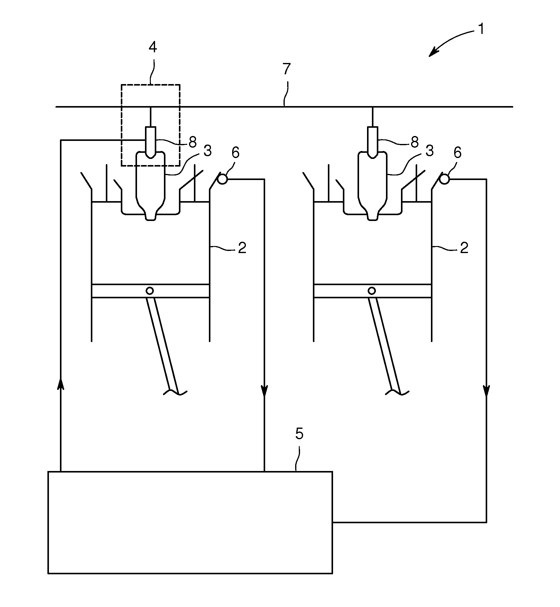
[0029] FIG. 1 shows an internal combustion engine 1 with several combustion chambers 2, each of which is connected to an antechamber 3. Each antechamber 2 has a gas supply device 4, which is designed here in the form of active antechamber gas valves 8 connected to an antechamber gas line 7. A control unit 5 (which is normally designed as a motor control device of the internal combustion engine) controls the gas supply to the antechambers 2. For each combustion chamber 2, there is a temperature sensor 6 for measuring an exhaust gas temperature T of an exhaust gas generated in the combustion chamber 2, whereby the temperature sensors 6 are connected to the control unit 5.
[0030] The control unit 5 is designed to perform a targeted disturbance .DELTA.u of the quantity of gas m supplied by means of the gas supply devices 4 to the individual antechambers 3 (e.g. by a slight change in the pressure in the antechamber gas line 7 or a change in an opening duration and/or an opening time of the antechamber gas valves 8) and by means of the temperature sensors 6 to measure the change .DELTA.T in the exhaust gas temperature T resulting from the targeted disturbance .DELTA.u for each combustion chamber 2. By a comparison with a stored target value of the change .DELTA.T.sub.target in the exhaust gas temperature T, the control unit 5 can deduce the quantity of gas m supplied by means of the gas supply device 4.
[0031] Alternatively or additionally, it could be provided that the control unit 5 is designed to determine a difference by comparing the resulting changes .DELTA.T in the exhaust gas temperatures T and to actuate at least one of the antechambers 3 such that the difference disappears. If the internal combustion engine has a common antechamber gas line 7 and passive gas valves which connect the individual antechambers 3 to the common antechamber gas line 7, the targeted disturbance .DELTA.u can only be performed globally (i.e. equally for all antechambers 3). In this case, after detecting a deviation in the quantity of gas supplied, no individual actuation can be performed in order to achieve equalization, but an exchange of the passive gas valve concerned would have to be performed. If active antechamber gas valves are provided, it is also possible to perform an equalization in the case of a common antechamber gas line 7 by individual actuation of at least one of the gas valves.
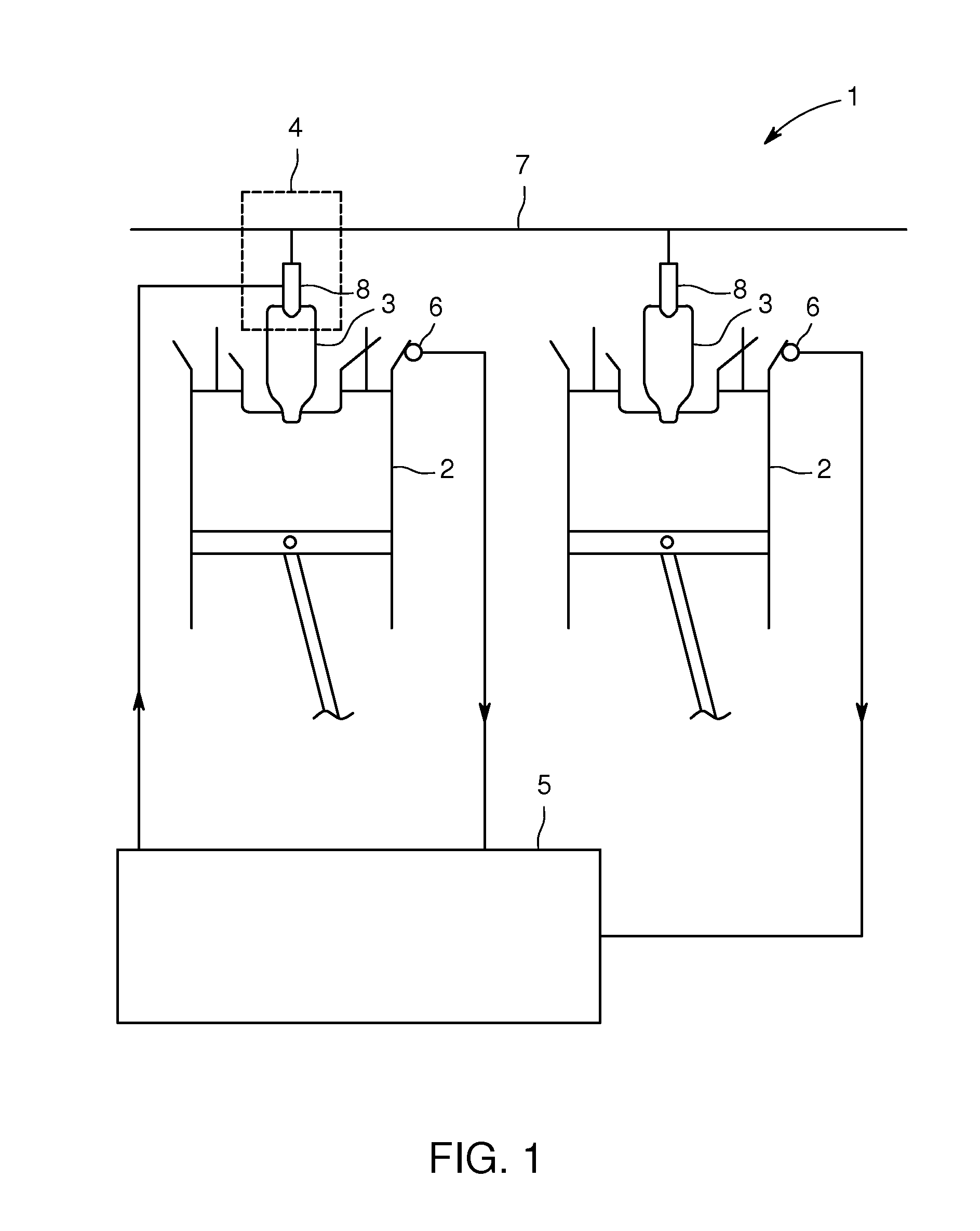
[0032] FIG. 2 shows an internal combustion engine 1 which differs from that of FIG. 1 only in that, here, the gas supply devices 4 are designed as channels which are closed with a nonreturn valve and connected to an antechamber gas line 7. The control unit 5 can vary the pressure in the antechamber gas line 7 via actuators (not shown).
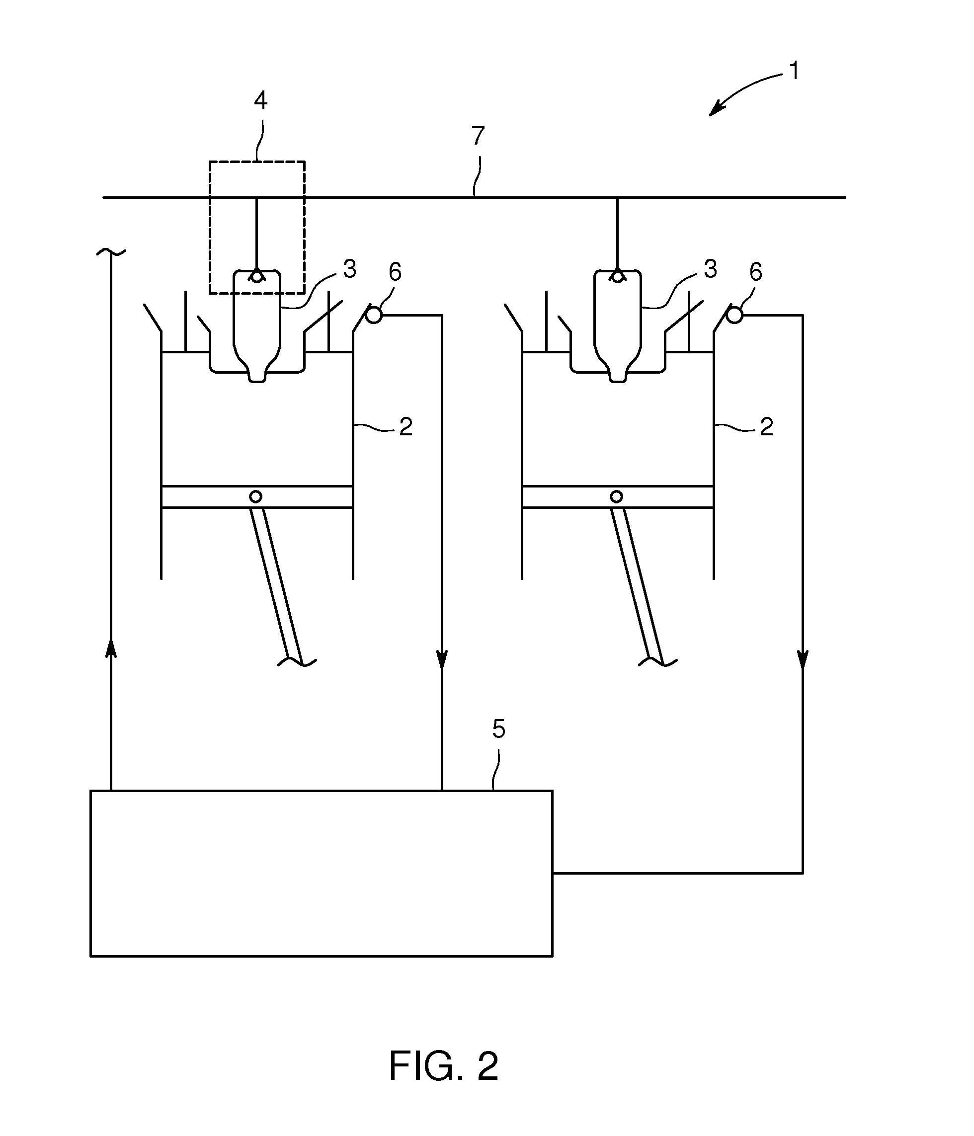
[0033] FIG. 3 shows a change in the exhaust gas temperature To which occurs in the case of a targeted disturbance .DELTA.u.sub.1 (here in the direction of a smaller quantity of gas m), which existed before the disturbance .DELTA.u.sub.1, to a value T.sub.1 which results from the disturbance .DELTA.u.sub.1, so that the disturbance .DELTA.u.sub.1 is connected to a change in the exhaust gas temperature .DELTA.T.
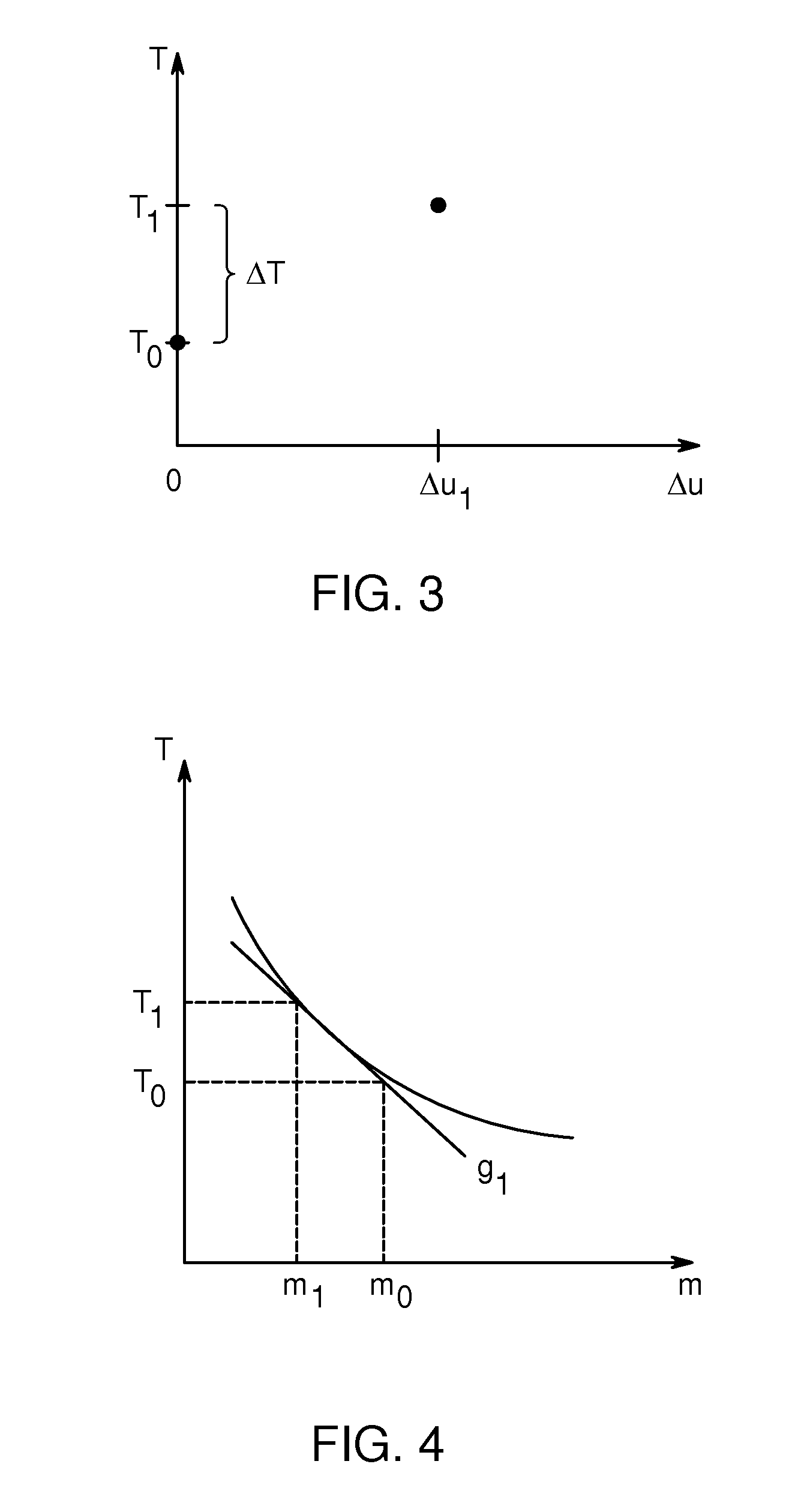
[0034] FIG. 4 shows schematically a relationship between the exhaust gas temperature T of an exhaust gas produced in the combustion chamber 2 connected to the antechamber 3 and the quantity of gas m which is supplied to the antechamber 3 by means of the gas supply device 4.
[0035] The tangent existing at a point m with a slope corresponding to the gradient dT/dm can be approximated by the drawn secant with the slope g.sub.1=(T.sub.0-T.sub.1)/(m.sub.0-m.sub.1). If the change in the exhaust gas temperature .DELTA.T resulting from the disturbance .DELTA.u.sub.1 is known, then it is possible to calculate the quotient .DELTA.T/.DELTA.u.sub.1 and determine the point m.sub.0 at which an identical slope or an identical gradient is present. This point m.sub.0 corresponds to the quantity of gas m which is supplied to the antechamber 3 of the internal combustion engine 1 by means of the gas supply device 4.
* * * * *
D00000
D00001
D00002
D00003
XML
uspto.report is an independent third-party trademark research tool that is not affiliated, endorsed, or sponsored by the United States Patent and Trademark Office (USPTO) or any other governmental organization. The information provided by uspto.report is based on publicly available data at the time of writing and is intended for informational purposes only.
While we strive to provide accurate and up-to-date information, we do not guarantee the accuracy, completeness, reliability, or suitability of the information displayed on this site. The use of this site is at your own risk. Any reliance you place on such information is therefore strictly at your own risk.
All official trademark data, including owner information, should be verified by visiting the official USPTO website at www.uspto.gov. This site is not intended to replace professional legal advice and should not be used as a substitute for consulting with a legal professional who is knowledgeable about trademark law.