Steam Generator Turbine
Vandigriff; John Edward ; et al.
U.S. patent application number 15/998025 was filed with the patent office on 2019-05-30 for steam generator turbine. The applicant listed for this patent is Einar Arvid Orbeck, JR., John Edward Vandigriff. Invention is credited to Einar Arvid Orbeck, JR., John Edward Vandigriff.
| Application Number | 20190162081 15/998025 |
| Document ID | / |
| Family ID | 66634956 |
| Filed Date | 2019-05-30 |
| United States Patent Application | 20190162081 |
| Kind Code | A1 |
| Vandigriff; John Edward ; et al. | May 30, 2019 |
STEAM GENERATOR TURBINE
Abstract
A turbine-generator system that uses high pressure steam to turn a turbine connected to a power generator. High pressure steam is generated by a continuous flow of pressurized water. The pressure steam generator can be configured as a separate unit, or as a part of the turbine. Steam is applied to the turbine from one high pressure steam unit through at least one nozzle, applying the steam against the turbine blades.
| Inventors: | Vandigriff; John Edward; (Carrollton, TX) ; Orbeck, JR.; Einar Arvid; (Las Vegas, NV) | ||||||||||
| Applicant: |
|
||||||||||
|---|---|---|---|---|---|---|---|---|---|---|---|
| Family ID: | 66634956 | ||||||||||
| Appl. No.: | 15/998025 | ||||||||||
| Filed: | June 15, 2018 |
Related U.S. Patent Documents
| Application Number | Filing Date | Patent Number | ||
|---|---|---|---|---|
| 15732321 | Oct 24, 2017 | |||
| 15998025 | ||||
| Current U.S. Class: | 1/1 |
| Current CPC Class: | F22B 1/30 20130101; F01K 11/02 20130101; F01K 9/003 20130101; F01K 7/165 20130101 |
| International Class: | F01K 7/16 20060101 F01K007/16; F01K 11/02 20060101 F01K011/02; F22B 1/30 20060101 F22B001/30; F01K 9/00 20060101 F01K009/00 |
Claims
1. A turbine-generator system including a high pressure steam unit which supplies steam to turn a turbine which is connected to a power generator, the high pressure steam unit is controlled by a control unit, the control unit controls the amount and pressure of the water supplied to the steam generator, the water being a continuous stream of high pressure water, and the control unit controls the amount of power supplied to the high pressure steam unit, the steam in the steam unit is created by passing an electrical current between electrical elements in the steam unit and through the high pressure water passed through the steam unit.
2. A turbine-generator system according to claim 1, wherein the high pressure water passed through the steam generator is supplied from a source outside and not included in turbine-generator system.
3. A turbine-generator system according to claim 1, wherein the high pressure steam unit is powered by a power source including one of a three phase 480 volt AC power, three phase 208 volt AC power, 120 volt three phase AC, 120 volt AC single phase, 240 volt AC single phase, 12 volt DC and 24 volt DC one of which is applied to the high pressure steam unit and controlled by the control unit.
4. A turbine-generator system according to claim 3, wherein the high pressure steam unit is one of a single phase unit, and a three phase unit, the two phase unit has two electrical elements and the three phase unit input uses three electrical elements.
5. A turbine-generator system according to claim 1 in which the turbine has multiple blades against which the high pressure steam produced in the high pressure steam unit is applied, and after the steam condenses back to water, the water is recycled and is directed back into the high pressure steam unit.
6. The turbine-generator system according to claim 5, where the recycled water flows through a one way valve to prevent a back flow of water into the turbine.
7. A high pressure steam unit which supplies high pressure steam to rotate a turbine, the turbine rotating a generator which supplies power, a portion of which is returned to the high pressure steam unit through a control unit which controls the pressure and temperature of the produced steam and a current that flows through water in the steam unit between electrical elements in the steam unit.
8. The high pressure steam unit according to claim 7, wherein a high pressure flow of water, supplied by a water pump from an outside source, is applied to the high pressure steam unit, the high pressure flow of water is controlled by a control unit which regulates the steam out to maintain a constant flow of steam at a desired pressure and temperature.
9. A turbine-generator system that uses a high pressure steam unit to turn a turbine which is connected to a power generator, the high pressure steam unit is controlled by a control unit, the control unit controls the amount and pressure of the water supplied to the high pressure steam unit and the amount of power supplied to the high pressure steam unit, the power supplied to the high pressure steam unit being one of DC voltage, single phase AC voltage, and three phase AC voltage.
10. A turbine-generator system according to claim 9, wherein a single phase unit has two electrical elements and a three phase input uses three electrical elements, a voltage that is applied to the electrical elements passes between the electrical elements and through water supplied to the steam unit to produce steam in the high pressure steam unit.
Description
FIELD OF THE INVENTION
[0001] The invention relates to a steam turbine system for generating power, and more particularly to a high pressure stream generator that rotates a turbine and power generator.
BACKGROUND OF THE INVENTION
[0002] Steam generator systems generally have a boiler in which water is heated to produce steam. The large boilers take up a large space. New technology uses electrodes to which a voltage is applied to heat the water in which the electrodes are placed to produce steam. In these systems, the water in which the electrodes are placed has to be replaced periodically to continue the production of steam. The steam generated is used to drive a turbine. In some prior art systems, there is a flow of water, but it is not a direct pressurized flow between and around electrical elements.
SUMMARY OF THE INVENTION
[0003] The technical advance represented by the invention as well as the objects thereof will become apparent from the following description of a preferred embodiment of the invention when considered in conjunction with the accompanying drawings, and the novel features set forth in the appended claims.
BRIEF DESCRIPTION OF THE DRAWINGS
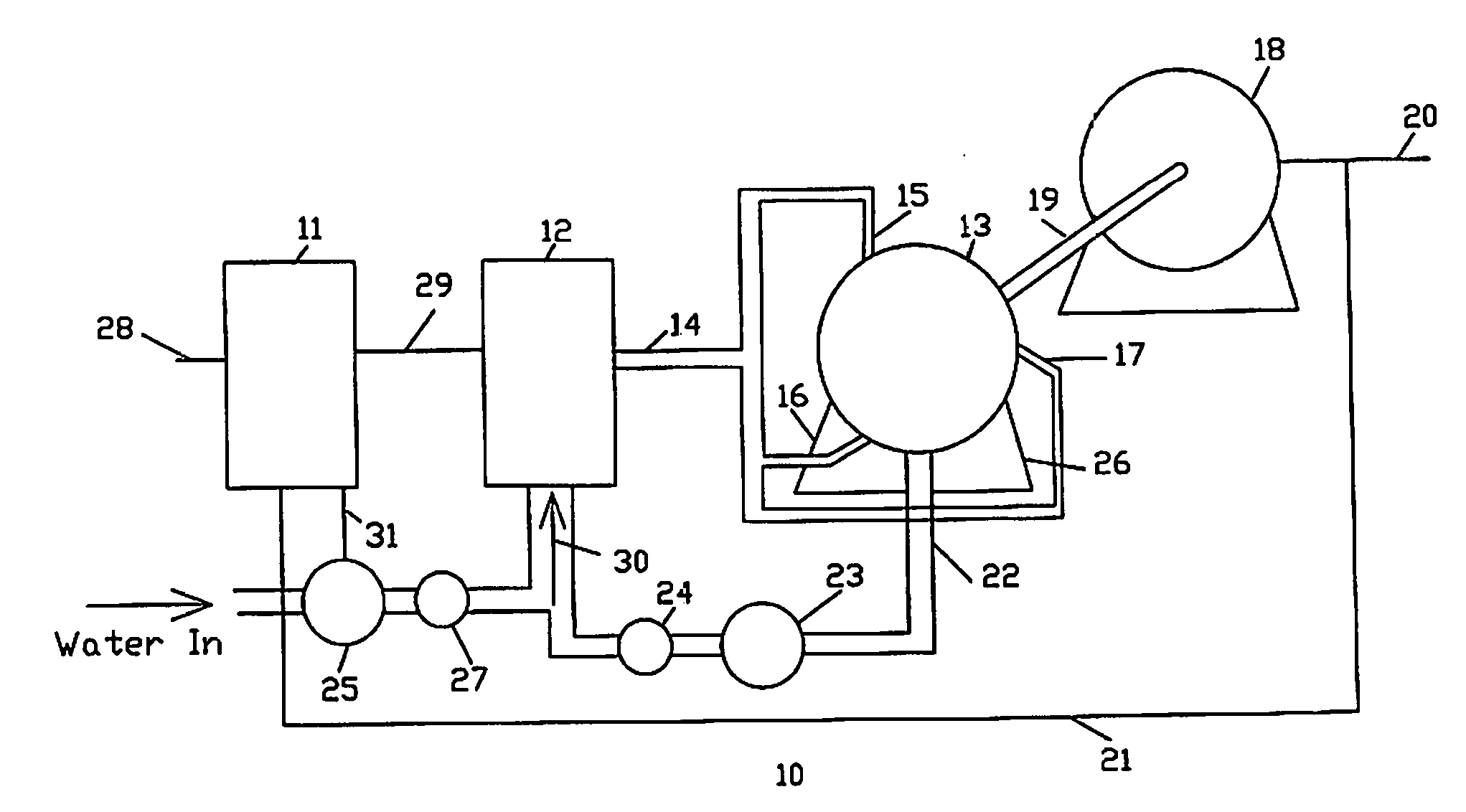
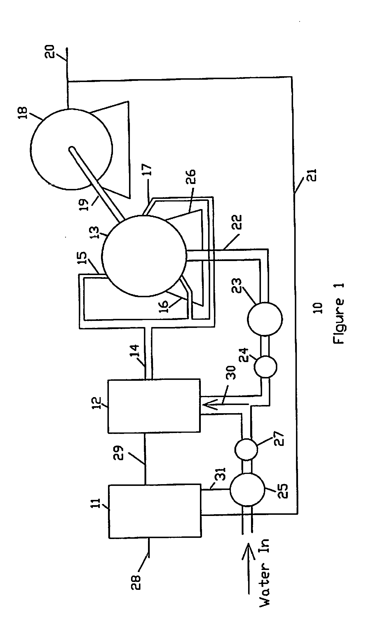
[0004] FIG. 1 illustrates the steam turbine system wherein the high pressure steam generator is separate from the turbine.
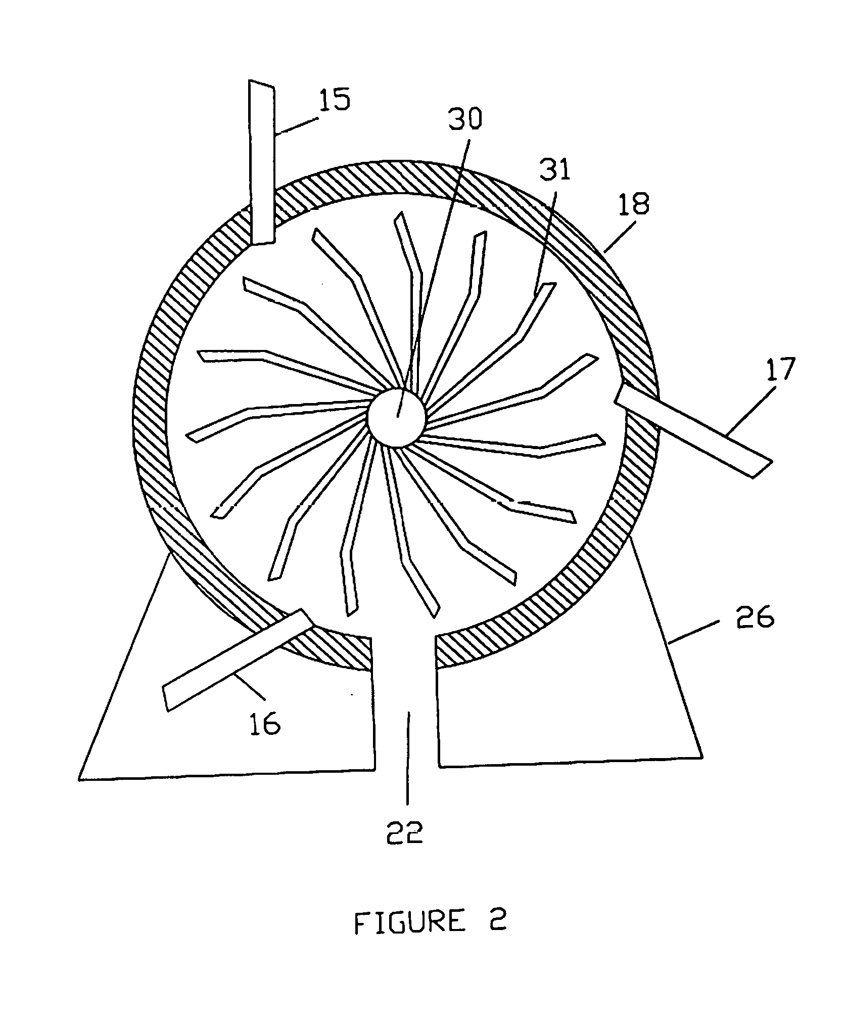
[0005] FIG. 2 shows a basic configuration of the turbine where high pressure steam in inserted into the turbine at three places to drive the turbine.
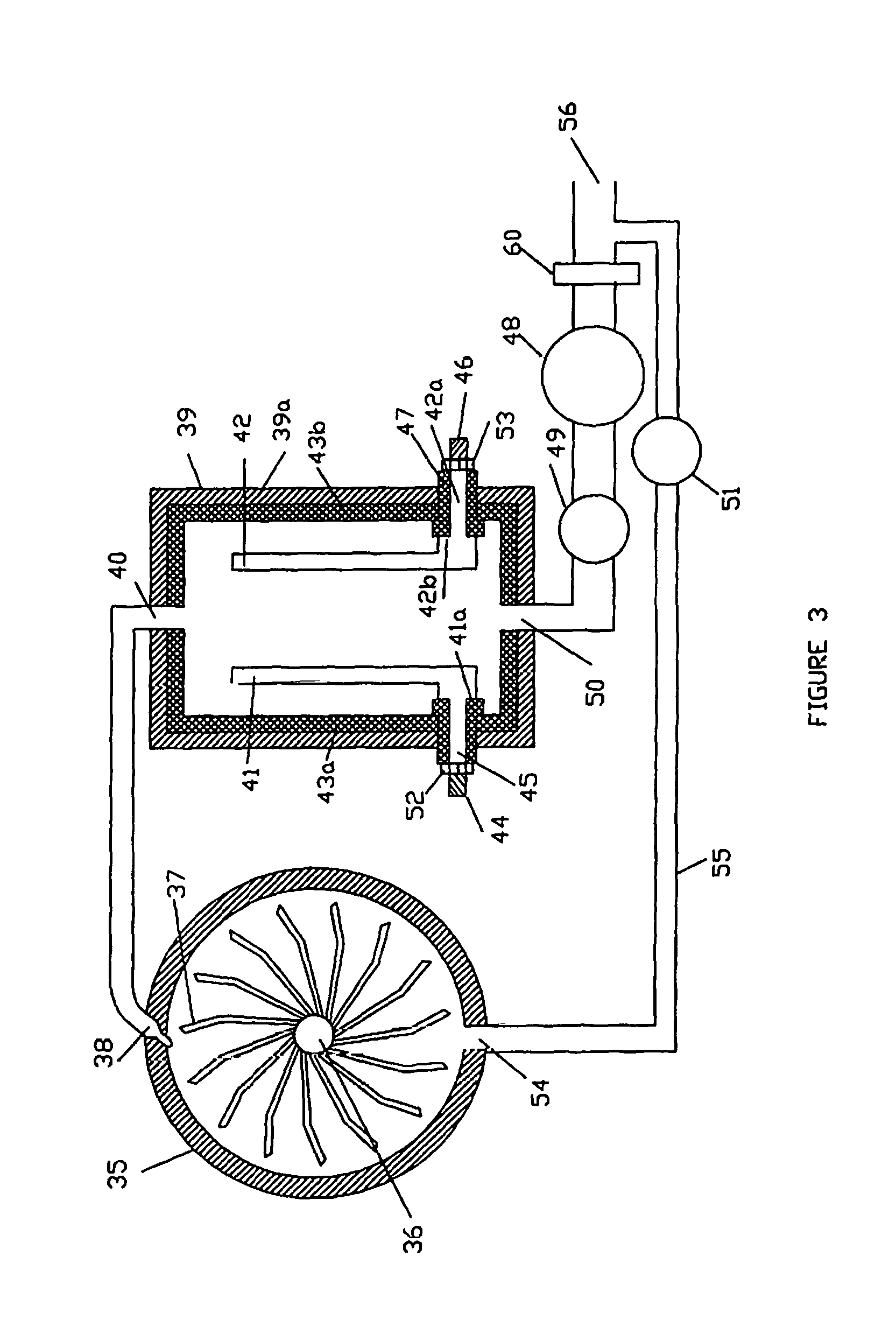
[0006] FIG. 3 shows one example of a steam unit connected to a turbine.
DESCRIPTION OF A PREFERRED EMBODIMENT
[0007] FIG. 1 illustrates a power generation system that utilizes a high pressure steam stream to run a turbine that turns a power generator. The system 10 has a controller unit 11 into which power is supplied at 28 and the control unit 11 supplies and controls the amount of power to the steam generator unit 12 by input 29. A continuous supply of pressurized water is input to the steam unit 12 by pump 25 and through a one way valve 27. Pump 25 is controlled by control unit 11 by control line 31 to regulate the pressure and amount of water flow.
[0008] Steam is produced in steam unit 12 by converting the continuous pressurized flow of water 30 into high pressure steam by passing the water between and around electrical elements in the steam unit 12 (FIG. 3), the power supplied and regulated by the control unit 11 by connection 29. The flow of current between the electrical elements passes through the water turning it into high pressure steam.
[0009] Steam passes through connection 14 and through nozzles 15, 16 and 17 (FIG. 2) into the turbine 13, rotating the turbine and rotating shaft 19 which turns the generator 18. Nozzles 15, 16 and 17 direct the high pressure steam against multi rotating blades which, with the pressure of steam against them, rotate the turbine.
[0010] The turbine 13 is mounted on base 26. At the bottom of the turbine there is an outlet 22 which passes water resulting from the condensed steam. This water passes through a pump 23 and one way valve 24 back into the steam system 12. This reduces the amount of water required through pump 25 after the turbine system is up and running.
[0011] Power output of the turbine 18 is at 20. This output is also returned to the control unit by connection 21. When the steam unit 12 first starts up producing steam, a large current is required. After the steam unit has been operating for a while, the amount of current to maintain the high pressure stream decrease because the steam is less conductive than the water. This allows the steam unit 12 to produce and maintain the stream of steam at a lower current. The current returned 21 from the turbine 18 can then be used to power a high percent of the current needed to power the steam unit.
[0012] FIG. 2 shows a sectional view of one example of turbine 18. Steam is supplied to nozzles 15, 16 and 17 and is directed against the upper part of the turbine rotating elements 31. These elements 31 extend up from the rotating shaft 30. The force of the high pressure steam against the elements 31 turning the turbine and the generator 18 (FIG. 1) connected by shaft 19 (FIG. 1).
[0013] FIG. 3 illustrates a sectional view of a turbine 35 and a steam generation unit 39. The turbine is similar to the turbine in FIG. 2, but is supplied with the driving steam only at one point, however multiple points could be used. Steam from generation unit 39 is inserted into turbine 35 through nozzle 38 which is directed directly at the turbine rotors 37, rotating them around rotating shaft 36. When the steam is condensed to water is exits the turbine at opening 54, rotating shaft 36 which extends and also rotate a generator as illustrated in FIG. 1.
[0014] The steam unit 39 consists of a metal housing 39a which has an internal insulation of ceramic 43a and 43b. Two electrical elements are mounted in steam unit 39 with long portions 41 and 42 extending inside partially along, but spaced apart from the inter ceramic coating. Each electrical element has an L-shaped end, 41a and 42a which extend through the metal housing wall 39. The part 41a extends though the metal housing through a ceramic part 45 and part 42a extends through the metal housing through a ceramic part 47. The electrical elements are then secured in place by bolts 52 and 53. It is necessary that the extension of the electrical elements must be hermetically sealed to prevent steam from exiting out around the portions of the electrical elements extending through the housing wall. The seal is created by the interface 42b of element 42 with the ceramic part 47 and the interface 42b with the internal ceramic wall 43b. Similarly, the interface between 41a and ceramic part 45 and the interface between the ceramic 43a with the ceramic part 45 provide the seal at that point.
[0015] Steam within the steam unit 39 is produced by inserting pressurized water through pump 48 and one way valve 49 into the steam unit opening 50. Power is applied to the terminals 44 and 46. In this example of a steam unit, single phase power is used. In the unit is FIG. 1, a three phase power in used. Power can be supplied by one of 12 volts DC, 120 volts AC single phase, 240 volt AC single phase, 208 AC volt 3-phase and 480 volts AC 3-phase. In the DC and two phase systems, only two electrical elements are used. In the three phase system, three electrical elements are used. The power applied depends upon the desired output pressure and temperature of the steam. When the pressurized water is inserted into the steam unit, the water flows upward and around the electrical elements. The conductive property of the water conducts currents between the electrical elements, heating the water and causes it to become steam. The water used does not have to be pure water, but may be brine water and other forms of contaminate water. The water directed into the pump 48 may be filtered by a filter 60 to removed particulate matter.
* * * * *
D00000
D00001
D00002
D00003
XML
uspto.report is an independent third-party trademark research tool that is not affiliated, endorsed, or sponsored by the United States Patent and Trademark Office (USPTO) or any other governmental organization. The information provided by uspto.report is based on publicly available data at the time of writing and is intended for informational purposes only.
While we strive to provide accurate and up-to-date information, we do not guarantee the accuracy, completeness, reliability, or suitability of the information displayed on this site. The use of this site is at your own risk. Any reliance you place on such information is therefore strictly at your own risk.
All official trademark data, including owner information, should be verified by visiting the official USPTO website at www.uspto.gov. This site is not intended to replace professional legal advice and should not be used as a substitute for consulting with a legal professional who is knowledgeable about trademark law.