Method And Apparatus For Washing An Upper Completion
WOIE; Rune
U.S. patent application number 16/196207 was filed with the patent office on 2019-05-30 for method and apparatus for washing an upper completion. The applicant listed for this patent is ConocoPhillips Company. Invention is credited to Rune WOIE.
| Application Number | 20190162049 16/196207 |
| Document ID | / |
| Family ID | 66630774 |
| Filed Date | 2019-05-30 |


| United States Patent Application | 20190162049 |
| Kind Code | A1 |
| WOIE; Rune | May 30, 2019 |
METHOD AND APPARATUS FOR WASHING AN UPPER COMPLETION
Abstract
The invention relates to the cleaning of a wellbore including a reservoir liner 3 and an upper portion 2 of the wellbore, by running in only one string into the wellbore and performing a reservoir liner cementing operation, displacing the cement 7 with completion fluid 8, followed using the same string to circulate mud in the upper completion, perform an inflow test on the reservoir liner 3, wash the upper completion and displace it to completion fluid 8.
| Inventors: | WOIE; Rune; (Tananger, NO) | ||||||||||
| Applicant: |
|
||||||||||
|---|---|---|---|---|---|---|---|---|---|---|---|
| Family ID: | 66630774 | ||||||||||
| Appl. No.: | 16/196207 | ||||||||||
| Filed: | November 20, 2018 |
Related U.S. Patent Documents
| Application Number | Filing Date | Patent Number | ||
|---|---|---|---|---|
| 62591025 | Nov 27, 2017 | |||
| Current U.S. Class: | 1/1 |
| Current CPC Class: | E21B 37/02 20130101; E21B 47/117 20200501; E21B 34/06 20130101; E21B 47/005 20200501; E21B 33/14 20130101; E21B 2200/04 20200501 |
| International Class: | E21B 37/02 20060101 E21B037/02; E21B 47/10 20060101 E21B047/10; E21B 33/14 20060101 E21B033/14 |
Claims
1. A process for washing a wellbore, the process comprising: a) passing a drill string, including a reservoir liner hanger running tool, down a cased wellbore to install a reservoir liner in an uncased distal portion of the wellbore; b) displacing cement into the reservoir liner annulus by passing completion fluid through the drill string and reservoir liner; c) without first removing the drill string from the wellbore, performing an inflow test on the reservoir liner; and d) washing the interior of the casing by passing wash fluid through the drill string and into the casing, whilst rotating the drill string.
2. A process as claimed in claim 1 comprising, prior to step (c), circulating drilling mud through the drill string and cased wellbore.
3. A process as claimed in claim 1 comprising, prior to step (c), scraping a portion of the interior surface of the casing of the wellbore to prepare it to have a production packer set.
4. A process as claimed in claim 1 wherein the step of performing an inflow test comprises partly filling the drill string with a fluid, such as base oil, having a lower density than the completion fluid in the reservoir liner and then forming a sealed connection between the drill string and reservoir liner, relieving pressure on the drill string fluid and testing for backflow of fluid from the reservoir liner.
5. A process as claimed in claim 4 wherein the sealed connection between the drill string and reservoir liner is made by inserting a tool at the distal end of the drill string into a polished bore receptacle of the reservoir liner hanger.
6. A process as claimed in claim 1 wherein, after step (b) a seal is placed at the top of the reservoir liner to prevent solid material falling into the reservoir liner.
7. Apparatus for washing a cased wellbore comprising a drill pipe having an assembly fitted to a distal end thereof, the assembly comprising: a) a reservoir liner hanger and reservoir liner hanger running tool; and b) an inflow test tool capable of forming a sealed connection between the drill string and the reservoir liner or reservoir liner hanger, for performing an inflow test on the reservoir liner.
8. Apparatus as claimed in claim 7 wherein the inflow test tool makes a sealed connection with a component of a reservoir liner or a component of the reservoir liner hanger, such as a polished bore receptacle of the reservoir liner hanger.
9. Apparatus as claimed in claim 7 further comprising a scraper for cleaning a portion of the interior of the casing to receive a production packer.
Description
CROSS-REFERENCE TO RELATED APPLICATIONS
[0001] This application is a non-provisional application which claims benefit under 35 USC .sctn. 119(e) to U.S. Provisional Application Ser. No. 62/591,025 filed Nov. 27, 2017, entitled "METHOD AND APPARATUS FOR WASHING AN UPPER COMPLETION," which is incorporated herein in its entirety.
STATEMENT REGARDING FEDERALLY SPONSORED RESEARCH OR DEVELOPMENT
[0002] None.
FIELD OF THE INVENTION
[0003] This invention relates to the washing of a cased length of a hydrocarbon production well or water injector well, above the reservoir liner and in particular to a method and apparatus for achieving such washing efficiently and making savings on the amount of time needed for the washing operation.
BACKGROUND OF THE INVENTION
[0004] When a hydrocarbon well, or water injector well is drilled, casing is installed in the upper region of the well and then, normally, a reservoir liner is run into the well on drill pipe equipped with a reservoir liner hanger. Once the reservoir liner hanger is in place, cement is displaced into the reservoir liner and back up the annulus outside the reservoir liner, cementing it in position, and the liner left filled with drilling mud. At this stage mud is circulated in the casing to remove residual cement, metal swarf, etc. The drill string is removed and a special cleanout string run in to the end of the reservoir liner. The casing and reservoir liner are then washed out with various fluids, and the portion of the casing in which the production packer is to be set is further cleaned with a scraper device. The well is thereby put into a suitable state to be filled with completion fluid and completed. The well cleanout string is relatively delicate since it must be narrow enough to extend through the reservoir liner. Because it is delicate it needs to be run in slowly.
[0005] Casing wash tooling is specially designed for the operation. It is designed to be rotated in the well; this is necessary in order to achieve effective washing. Since the well may be highly deviated, the string tends to lie on the lower side of the casing and, in the absence of rotation, only the region above the string will be effectively washed.
[0006] The casing wash tooling is also specially designed to carry out a so-called inflow test to check that there is no leakage of fluid from the reservoir liner or into the reservoir or production casing/liner. The casing wash process takes many days with associated cost and it is desirable to reduce this. The process is also risky since the thin cleanout string which passes down the reservoir liner is delicate and easily damaged.
BRIEF SUMMARY OF THE DISCLOSURE
[0007] According to the invention a process for washing a wellbore comprises passing a drill string, including a reservoir liner hanger running tool, down a cased wellbore to install a reservoir liner in an uncased distal portion of the wellbore; displacing cement into the reservoir liner annulus by passing completion fluid through the drill string and reservoir liner; without first removing the drill string from the wellbore, performing an inflow test on the reservoir liner; and washing the interior of the casing by passing wash fluid through the drill string and into the casing, whilst rotating the drill string.
[0008] Also according to the invention, an apparatus for washing a cased wellbore comprises a drill pipe having an assembly fitted to a distal end thereof, the assembly comprising: a reservoir liner hanger and reservoir liner hanger running tool; and an inflow test tool capable of forming a sealed connection between the drill string and the reservoir liner or reservoir liner hanger, for performing an inflow test on the reservoir liner.
BRIEF DESCRIPTION OF THE DRAWINGS
[0009] A more complete understanding of the present invention and benefits thereof may be acquired by referring to the follow description taken in conjunction with the accompanying drawings in which:
[0010] FIG. 1 is a schematic sectional view of a wellbore comprising a cased upper region above a reservoir liner, prior to a reservoir liner cementing operation;
[0011] FIG. 2 is a schematic sectional view of the wellbore after cementing of the liner;
[0012] FIG. 3 is a schematic sectional view of the wellbore with drilling mud being circulated in the upper region of the well;
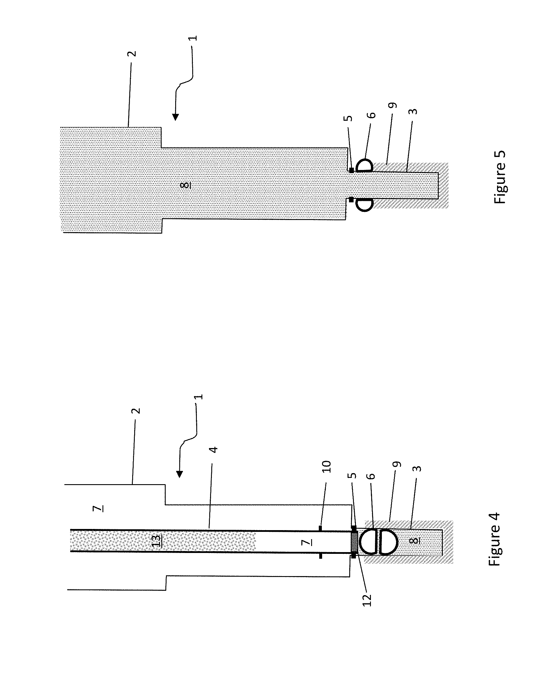
[0013] FIG. 4 is a schematic sectional view of the wellbore showing the configuration for an inflow test
[0014] FIG. 5 a schematic sectional view of the wellbore showing the entire wellbore filled with completion fluid.
DETAILED DESCRIPTION
[0015] Turning now to the detailed description of the preferred arrangement or arrangements of the present invention, it should be understood that the inventive features and concepts may be manifested in other arrangements and that the scope of the invention is not limited to the embodiments described or illustrated. The scope of the invention is intended only to be limited by the scope of the claims that follow.
[0016] Referring firstly to FIG. 1, a wellbore 1 comprises an upper, cased part 2 underneath which is a reservoir liner 3. Extending through the wellbore approximately to the junction between the upper part 2 and reservoir liner 3 is a drill string 4. At the distal end of the drill string is an assembly comprising a reservoir liner hanger 5, associated reservoir liner hanger running tool 10, which in FIG. 1 is connected to the reservoir liner hanger, and a ball valve 6. The assembly also comprises a scraper tool for cleaning a section of the interior of the casing above the reservoir liner hanger 5. At the distal end of the reservoir liner is a burst disc. The scraper tool and burst disc are omitted from the drawings for clarity. They are standard components whose design and functionality will be familiar to anyone of ordinary skill in this field. The function of all these components will be described below. At the distal end of the drill string 4 is an inflow test seal, also omitted from the drawings for clarity and whose function will be explained below.
[0017] At the stage illustrated in FIG. 1, the reservoir liner 3 has been placed by the drill string 4 at a desired depth. The reservoir liner hanger 5 has not yet been set. The wellbore is filled with drilling mud 7 to balance/control the well pressures. In an alternative method, the reservoir liner hanger is set before the cement is displaced.
[0018] Referring to FIG. 2, a cementing job is now performed by introducing cement into the drill string 4. A volume of cement sufficient to fill the annulus around the reservoir liner 3 is introduced into the drill string 4, immediately followed by a cleaning plug and completion fluid 8 (in this case, brine). As the completion fluid displaces the cement through the reservoir liner 3, the cleaning plug substantially prevents cement being left on the reservoir liner interior wall.
[0019] An appropriate volume of completion fluid 8 is pumped down the drill string 4 to displace all the cement into the annulus of 3. Cement filling the annulus is shown at 9 in FIG. 2. At this point the drill string 4 and the entire length of the internal bore of the reservoir liner 3 are filled with brine 8. The reservoir liner hanger will now be set, anchoring the reservoir liner 3 to the upper, cased part 2 and creating a continuous seal between these.
[0020] The drill string 4 is then withdrawn slightly so that its distal end, with the reservoir liner hanger running tool 10, is detached from and right above the reservoir liner hanger 5. This action closes the ball valve 6 by pulling a shifting tool past a shifting profile (a technique for actuating down-hole components which is well known in this field). This state is shown in FIG. 3. The ball valve 6 keeps the completion fluid 8 in the reservoir liner 3 separated from the upper, cased well volume 2 above, i.e. prevents debris from the upper part of the well from falling into the reservoir liner. The closing of the valve 6 is not limited to pulling a shifting tool past a shifting profile, but could also be achieved by a clock timer, pressure pulses, or any other technique known generally in this field. The ball valve 6 could be replaced by any suitable type of mechanical valve, e.g. a flapper valve, but a ball valve is preferred because the ball valve can also act to prevent fluid flow in the opposite sense, e.g. as a barrier in case of a leak in the reservoir liner.
[0021] The ball valve 6 is actuated by the drill string being withdrawn, and this helps prevent the completion fluid in the reservoir liner from becoming contaminated with solid material from above.
[0022] In a modified apparatus and method, the ball valve 6 is not present, nor circulation is started. The inventor believes that the process for cleaning of the upper completion, as described below, is so short (perhaps of the order of 2 hours) that this will give rise to very little, if any, solid material falling into the reservoir liner even if no valve is present. The short time for the cleaning operation means that there may be insufficient time for the drilling mud to heat up appreciably; it is when the drilling mud becomes hot (i.e. is heated to the temperature of the formation which can be around 150 degrees Celsius or more) that solids (e.g. barite) tend to settle out of the mud, so for this reason also the valve 6 may not be necessary. With circulation started any debris from upper part of the well will not permitted entering the reservoir liner 3.
[0023] The casing scraper tool (not shown in the drawings) that was previously collapsed in the reservoir liner expands to scrape the production casing string that hosts the reservoir liner hanger 5. The drill string 4 is rotated and/or reciprocated, which causes the scraper tool to scrape clean a portion of the interior of the casing--the portion which will be received a production packer at a later stage in the completion of the well.
[0024] Drilling mud is continuously circulated, with the drill string rotating, to clean heavy debris from the upper part of the well, above the reservoir liner hanger. Debris such as cement and metal swarf can be removed by the heavy drilling mud. Rotation of the drill string ensures that the entire inner surface of the casing above the reservoir liner hanger is cleaned.
[0025] After circulation of mud, the rotation of the string is stopped and an underbalanced fluid is circulated down the drill string. This is shown in FIG. 4. The inflow seal is stung into a polished bore receptacle ("PBR") of the reservoir liner hanger. Although the inflow seal and PBR are not shown as such in the drawings, in FIG. 4 it can be seen that the end of the drill string is engaged once more with the liner hanger and a seal at the end of the drill string is schematically shown at 12.
[0026] The PBR need not be part of the liner hanger and may alternatively be provided on another part, above or below the liner hanger assembly. PBRs are well known in themselves and their structure and function will be apparent to one of ordinary skill in this field.
[0027] Together the inflow seal and PBR provide a temporary seal between the drill string and reservoir liner, isolating the interior of the drill string 4 and reservoir liner 3 from the annulus between the drill string and casing 2.
[0028] Once the seal between the drill string and PBR/reservoir liner engaged, the underbalanced fluid causes the reservoir liner to be underbalanced to the reservoir allowing the inflow test of the reservoir liner.
[0029] The underbalanced fluid in the drill string is created by displacing some of the mud in the string with a light oil or base oil, shown at 13 in FIG. 4, having a density lower than the completion fluid. If fluid in the drill string is detected coming to surface, this is an indication of a leak in the reservoir liner. It is important to conduct such an inflow test prior to completing the well.
[0030] In an alternative method, which saves time but is less safe because the degree of underbalance cannot be controlled, the mud in the drill string is simply displaced to completion fluid and the inflow test then done.
[0031] After the inflow test, the inflow seal is disengaged from the PBR and the underbalanced fluid in the drill pipe is circulated out of the well. The upper part of the wellbore washed with a wash train comprising a sequence of different fluids as is well known in this field. During this process the drill string is rotated. Rotation of the drill string throughout the washing provides for efficient displacement. The casing scraper tool may be employed again (or alternatively for the first time) at this point in the process. Reciprocation of the drill string causes the scraper to scrape the casing where the production packer for the upper completion will be placed and set after the drill string is retrieved.
[0032] Finally the upper part of the wellbore is displaced to completion fluid 8 and the drill string withdrawn. This is shown in FIG. 5.
[0033] The process described avoids the running of a separate cleanout string either to clean the reservoir liner or to clean out the upper part of the wellbore. Several days of rig time can be saved as well as avoiding the hazardous process of running a narrow cleanout string into the reservoir liner, which is prone to failure by buckling.
[0034] In closing, it should be noted that the discussion of any reference is not an admission that it is prior art to the present invention, especially any reference that may have a publication date after the priority date of this application. At the same time, each and every claim below is hereby incorporated into this detailed description or specification as a additional embodiments of the present invention.
[0035] Although the systems and processes described herein have been described in detail, it should be understood that various changes, substitutions, and alterations can be made without departing from the spirit and scope of the invention as defined by the following claims. Those skilled in the art may be able to study the preferred embodiments and identify other ways to practice the invention that are not exactly as described herein. It is the intent of the inventors that variations and equivalents of the invention are within the scope of the claims while the description, abstract and drawings are not to be used to limit the scope of the invention. The invention is specifically intended to be as broad as the claims below and their equivalents.
* * * * *
D00000
D00001
D00002
XML
uspto.report is an independent third-party trademark research tool that is not affiliated, endorsed, or sponsored by the United States Patent and Trademark Office (USPTO) or any other governmental organization. The information provided by uspto.report is based on publicly available data at the time of writing and is intended for informational purposes only.
While we strive to provide accurate and up-to-date information, we do not guarantee the accuracy, completeness, reliability, or suitability of the information displayed on this site. The use of this site is at your own risk. Any reliance you place on such information is therefore strictly at your own risk.
All official trademark data, including owner information, should be verified by visiting the official USPTO website at www.uspto.gov. This site is not intended to replace professional legal advice and should not be used as a substitute for consulting with a legal professional who is knowledgeable about trademark law.