Well Bladder System
O'Hare; Mark S. ; et al.
U.S. patent application number 16/205079 was filed with the patent office on 2019-05-30 for well bladder system. The applicant listed for this patent is Bleeding Edge EnSys LLC, Star Innovative Global Solutions Inc.. Invention is credited to Mark S. O'Hare, Susan Schmidt, George Sturmon.
| Application Number | 20190162043 16/205079 |
| Document ID | / |
| Family ID | 64665424 |
| Filed Date | 2019-05-30 |


View All Diagrams
| United States Patent Application | 20190162043 |
| Kind Code | A1 |
| O'Hare; Mark S. ; et al. | May 30, 2019 |
WELL BLADDER SYSTEM
Abstract
A well bladder is used to seal wellbores from intrusion. The well bladder is inserted, threaded, or otherwise arranged into the wellbore or an opening into the wellbore, and then expanded against the wellbore to seal against intrusion. The well bladder includes one or more layers, one or more axial sections, and one or more azimuthal sections. For example, the well bladder may be constructed from polyurethane, reinforcement, fabric, rubber, plastic, a composite material, or other flexible material. In a further example, the well bladder may include layers, mesh, fibers, stitching, or other suitable construction. In some embodiments, the well bladder may include a port configured to allow pressurization of the inner volume, a sensor configured to sense one or more properties of the well bladder, or both. A system may be configured to monitor the well bladder over time to ensure that the well bladder maintains the seal.
| Inventors: | O'Hare; Mark S.; (Coto De Caza, CA) ; Sturmon; George; (St. Charles, MO) ; Schmidt; Susan; (Sullivan, MO) | ||||||||||
| Applicant: |
|
||||||||||
|---|---|---|---|---|---|---|---|---|---|---|---|
| Family ID: | 64665424 | ||||||||||
| Appl. No.: | 16/205079 | ||||||||||
| Filed: | November 29, 2018 |
Related U.S. Patent Documents
| Application Number | Filing Date | Patent Number | ||
|---|---|---|---|---|
| 62593078 | Nov 30, 2017 | |||
| 62656298 | Apr 11, 2018 | |||
| Current U.S. Class: | 1/1 |
| Current CPC Class: | E21B 33/127 20130101; E21B 33/1285 20130101; E21B 47/00 20130101; E21B 33/1277 20130101 |
| International Class: | E21B 33/127 20060101 E21B033/127; E21B 47/00 20060101 E21B047/00 |
Claims
1. A well bladder for sealing a wellbore from intrusion, the well bladder comprising: a sidewall having a radial thickness configured to provide structural rigidity, the sidewall comprising: an inner surface that interfaces to an inner volume; and an outer surface that interfaces to a surface of the wellbore and configured to seal against the surface of the wellbore to prevent intrusion into the wellbore.
2. The well bladder of claim 1, further comprising a pressurized fluid in the inner volume, the pressurized fluid having a pressure greater than each of an atmospheric pressure and an intrusion pressure, wherein the pressurized fluid is configured to apply an outward pressure on the inner surface.
3. The well bladder of claim 1, further comprising a hardened foam in the inner volume, wherein the hardened foam is configured to apply an outward pressure on the inner surface.
4. The well bladder of claim 1, wherein the sidewall comprises one or more layers.
5. The well bladder of claim 4, wherein the sidewall comprises an inner layer and an outer layer, wherein the inner layer comprises the inner surface and the outer layer comprises the outer surface.
6. The well bladder of claim 5, wherein the outer layer comprises an aramid fiber material.
7. The well bladder of claim 5, wherein the inner layer comprises at least one material selected from the group: a plastic material; a polyurethane material; and a rubber material.
8. The well bladder of claim 1, wherein the sidewall comprises a reinforcement configured to provide rigidity to the sidewall.
9. The well bladder of claim 8, wherein the reinforcement comprises a fiber reinforcement.
10. The well bladder of claim 9, wherein the fiber reinforcement comprises one or more fibers comprising a tensile strength sufficient to strengthen the sidewall.
11. The well bladder of claim 10, wherein the fiber reinforcement is configured to not shear off or leak into a pre-existing fracture of the wellbore.
12. The well bladder of claim 8, wherein the reinforcement comprises a mesh reinforcement.
13. The well bladder of claim 1, further comprising a reinforcement configured to provide additional rigidity to the sidewall.
14. The well bladder of claim 13, wherein the reinforcement comprises a fiber reinforcement.
15. The well bladder of claim 14, wherein the fiber reinforcement comprises one or more fibers comprising a tensile strength sufficient to strengthen the well bladder.
16. The well bladder of claim 15, wherein the fiber reinforcement is configured to not shear off or leak into a pre-existing fracture of the wellbore.
17. The well bladder of claim 13, wherein the reinforcement comprises a mesh reinforcement.
18. The well bladder of claim 1 wherein the sidewall comprises one or more axial sections.
19. The well bladder of claim 1, wherein the sidewall comprises one or more azimuthal sections.
20. The well bladder of claim 1, further comprising one or more internal walls, wherein the inner surface defines the inner volume, wherein the inner volume is partitioned into two or more chambers by the one or more internal walls, and wherein the two or more chambers are configured to be pressurized independently from one another.
21. The well bladder of claim 1, configured to be contracted in size.
22. The well bladder of claim 21, wherein the sidewall comprises a pleat configured to allow the well bladder to be contracted in size.
23. The well bladder of claim 21, wherein the sidewall comprises a fold configured to allow the well bladder to be contracted in size.
24. The well bladder of claim 21, wherein the sidewall comprises a twist configured to allow the well bladder to be contracted in size.
25. The well bladder of claim 1, further comprising a port configured to be coupled to an auxiliary system for pressurizing the inner volume.
26. The well bladder of claim 1, having a length of between 100 and 5000 feet.
27. The well bladder of claim 1, wherein the outer surface comprises an outer diameter in a compressed state of less than 2 inches.
28. The well bladder of claim 1, wherein the outer surface comprises an outer diameter in an expanded state of between 1.5 and 4 inches.
29. The well bladder of claim 1, wherein the sidewall comprises a fabric material.
30. The well bladder of claim 1, further comprising an aramid fiber material.
31. The well bladder of claim 30, wherein the sidewall comprises the aramid fiber material.
32. The well bladder of claim 1, wherein the sidewall comprises a plastic material.
33. The well bladder of claim 1, wherein the sidewall comprises a rubber material.
34. The well bladder of claim 1, wherein the sidewall comprises a thermosetting polymer material.
35. The well bladder of claim 34, wherein the thermosetting polymer material comprises a polyurethane material.
36. The well bladder of claim 1, further comprising a weighted section having a density greater than an average density of the well bladder.
37. The well bladder of claim 1, further comprising a wrap configured to: restrain the well bladder to cause the well bladder to contract in size during installation; and release the well bladder at a predetermined stress to cause the well bladder to expand in the well bore when a pressurized medium is provided to the inner volume.
38. A method for deploying a well bladder for sealing a wellbore from intrusion, wherein the well bladder comprises: a sidewall having a radial thickness configured to provide structural rigidity, the sidewall comprising: an inner surface that interfaces to an inner volume; and an outer surface, the method comprising: arranging the well bladder in the wellbore to axially align with fractures of the wellbore; and providing a pressurized medium to the inner volume of the well bladder, wherein the pressurized medium causes a radially outward force to act on the sidewall, and wherein the radially outward force causes the sidewall to seal against the wellbore.
39. The method of claim 38, wherein providing the pressurized medium further comprises generating a control signal, using control circuitry, that causes an auxiliary system to provide the pressurized medium to the inner volume.
40. The method of claim 38, further comprising monitoring, using a sensor, at least one property of the well bladder over time.
41. The method of claim 40, wherein the at least one property comprises a pressure of the inner volume.
42. The method of claim 40, further comprising adjusting the at least one property of the well bladder using an auxiliary system based at least in part on the monitoring.
43. The method of claim 38, wherein the pressurized medium comprises a pressurized gas, the method further comprising compressing a gas to create the pressurized gas.
44. The method of claim 38, wherein the pressurized medium comprises a hardened foam.
45. The method of claim 38, wherein the pressurized medium comprises a pressurized liquid, the method further comprising pumping a liquid to create the pressurized liquid.
46. The method of claim 38, wherein the well bladder comprises a port coupled to the inner volume and to a valve, wherein providing the pressurized medium further comprises opening the valve.
47. The method of claim 46, further comprising closing the valve when at least one property of the well bladder exceeds a threshold value.
48. The method of claim 38, wherein arranging the well bladder in the wellbore comprises threading the well bladder through an opening in the wellbore.
49. The method of claim 38, wherein the well bladder is initially folded, and wherein arranging the well bladder in the wellbore comprises unfolding the well bladder within the wellbore.
50. The method of claim 38, wherein the well bladder is pleated, and wherein arranging the well bladder in the wellbore comprises unfolding the pleats of the well bladder within the wellbore.
51. The method of claim 38, wherein the well bladder is initially twisted, and wherein arranging the well bladder in the wellbore comprises untwisting the well bladder within the wellbore.
52. The method of claim 38, wherein the well bladder is initially arranged on a spool outside of the wellbore, and wherein arranging the well bladder in the wellbore comprises unspooling the well bladder into the wellbore.
53. The method of claim 38, wherein the well bladder is initially laid-out outside of the wellbore, and wherein arranging the well bladder in the wellbore comprises feeding the well bladder into the wellbore.
54. The method of claim 38, wherein the well bladder is initially rolled outside of the wellbore, and wherein arranging the well bladder in the wellbore comprises unrolling the well bladder into the wellbore.
55. The method of claim 38, wherein the well bladder further comprises a wrap configured to restrain the well bladder to maintain the well bladder contracted in size, and wherein providing the pressurized medium to the inner volume of the well bladder causes the wrap to rupture.
56. The method of claim 38, wherein the well bladder is initially coiled outside of the wellbore, and wherein arranging the well bladder in the wellbore comprises uncoiling the well bladder into the wellbore.
Description
[0001] The present disclosure is directed to a well bladder system and more particularly to a well bladder system configured to reduce intrusion. This application claims the benefit of U.S. Provisional Patent Application No. 62/593,078 filed Nov. 30, 2017, and U.S. Provisional Patent Application No. 62/656,298 filed Apr. 11, 2018, the disclosures of which are hereby incorporated by reference herein in their entireties.
BACKGROUND
[0002] Oil drilling and service companies sometimes place hydraulic fracturing ("fracking") wells in close proximity to existing productive wells. For example, when horizontal or vertical wells are drilled too close to one another within a shale field, they may have a negative impact on the recovery rates of the shale field. When stimulating new oil and gas wells, surrounding legacy wells may be impacted. For example, wells may be fracked-into from nearby hydraulic fracturing processes, wherein frack fluid, proppant and reservoir rock may enter into the corresponding wellbores. Accordingly, oil and gas companies can be subject to losing millions of dollars fixing the damages to existing wells caused by the frack-into interference. Because of the frack-into issue, thousands of wells are being plugged and abandoned each year, leaving oil and gas reserves stranded.
SUMMARY
[0003] It would be desirable to protect existing wellbores from frack-into issues, or other intrusion of material (e.g., gas, liquid, or solid), such that the wellbores may be used again.
[0004] In some embodiments, the present disclosure is directed to a well bladder for sealing a wellbore from intrusion. The well bladder also includes a sidewall having a radial thickness configured to provide structural rigidity. The sidewall includes an inner surface configured to interface to an inner volume. In some embodiments, the sidewall further may-include an outer surface configured to interface to a surface of the wellbore and to seal against the surface to prevent intrusion into the wellbore.
[0005] In some embodiments, the well bladder includes a pressurized gas or liquid in the inner volume having a pressure greater than each of an atmospheric pressure and an intrusion pressure. The pressurized gas or liquid is configured to apply an outward pressure on the inner surface.
[0006] In some embodiments, the well bladder includes a hardened foam in the inner volume. The hardened foam is configured to apply an outward pressure on the inner surface.
[0007] In some embodiments, the sidewall includes one or more layers. In some embodiments, the sidewall includes an inner layer and an outer layer, in which the inner layer includes the inner surface and the outer layer includes the outer surface.
[0008] In some embodiments, the sidewall includes a reinforcement configured to provide rigidity to the sidewall. For example, the reinforcement is strong enough to not shear off or leak into pre-existing fractures in a wellbore. In some embodiments, the reinforcement includes a fiber reinforcement. In some embodiments, the reinforcement includes a mesh reinforcement. In some embodiments, the reinforcement includes a non-fiber, non-mesh reinforcement.
[0009] In some embodiments, the well bladder includes a reinforcement configured to provide rigidity to the sidewall. For example, the reinforcement is strong enough to not shear off or leak into pre-existing fractures in a wellbore. In some embodiments, the reinforcement includes a fiber reinforcement. In some embodiments, the reinforcement includes a mesh reinforcement. In some embodiments, the reinforcement includes a non-fiber, non-mesh reinforcement.
[0010] In some embodiments, the sidewall includes one or more axial sections.
[0011] In some embodiments, the sidewall includes one or more azimuthal sections.
[0012] In some embodiments, the well bladder includes one or more internal walls. The inner surface defines an inner volume, which is partitioned into two or more chambers by the one or more internal walls. The two or more chambers are configured to be pressurized independently from one another.
[0013] In some embodiments, the well bladder is configured to be contracted in size. For example, in some circumstances, a well bladder is contracted in size for installation.
[0014] In some embodiments, the well bladder includes a port configured to be coupled to an auxiliary system for pressurizing the inner volume.
[0015] In some embodiments, the well bladder includes a length of between 100 and 5000 feet. In some embodiments, the length is greater than 5000 feet.
[0016] In some embodiments, the outer surface includes an outer diameter in a compressed state of less than 2 inches.
[0017] In some embodiments, the outer surface includes an outer diameter in an expanded state of between 2 and 4 inches. In some embodiments, the outer surface includes an outer diameter in an expanded state of greater than 4 inches.
[0018] In some embodiments, the sidewall includes a fabric material.
[0019] In some embodiments, the well bladder includes an aramid fiber material. In some embodiments, the well bladder does not, and need not, include an aramid fiber material.
[0020] In some embodiments, the sidewall includes the aramid fiber material.
[0021] In some embodiments, the sidewall includes a plastic material. In some embodiments, the plastic material includes a polyurethane material.
[0022] In some embodiments, the well bladder includes a weighted section having a density greater than an average density of the well bladder.
[0023] In some embodiments, the well bladder includes a wrap configured to restrain the well bladder to cause the well bladder to contract in size during installation and release the well bladder at a predetermined stress to cause the well bladder to expand in the well bore when a pressurized medium is provided to the inner volume.
[0024] In some embodiments, the present disclosure is directed to a method for deploying a well bladder for sealing a wellbore from intrusion. The well bladder includes a sidewall having a radial thickness configured to provide structural rigidity. The sidewall includes an inner surface that interfaces to an inner volume and an outer surface. The method includes arranging the well bladder in the wellbore to axially align with fractures of the wellbore. The method also includes providing a pressurized medium to the inner volume of the well bladder, wherein the pressurized medium causes a radially outward force to act on the sidewall, and wherein the radially outward force causes the sidewall to seal against the wellbore.
[0025] In some embodiments, providing the pressurized medium includes, that causes an auxiliary system to provide the pressurized medium to the inner volume. In some embodiments, providing the pressurized medium includes generating a control signal using analog control that causes an auxiliary system to provide the pressurized medium to the inner volume.
[0026] In some embodiments, the method includes monitoring, using a sensor, at least one property of the well bladder over time. In some embodiments, the method need not include monitoring at least one property of the well bladder over time.
[0027] In some embodiments, the at least one property includes a pressure of the inner volume. For example, in some embodiments, the method includes equalizing enough pressure in the inner volume to prevent external material to leach or flow into the well. The leaching or flowing can occur under normal conditions or can be caused by an external pressure outside the well that could cause leakage or damage to the internals of the existing well that is being protected.
[0028] In some embodiments, the method includes adjusting at least one property of the well bladder using an auxiliary system based at least in part on the monitoring.
[0029] In some embodiments, the pressurized medium includes a pressurized fluid such as gas, liquid, slurry, foam, or a combination thereof, and the method includes compressing or pressurizing the fluid to create the pressurized fluid.
[0030] In some embodiments, the pressurized medium includes a hardened foam, or stabilizing liquid or gas.
[0031] In some embodiments, the well bladder includes a port coupled to the inner volume and to a valve, and providing the pressurized medium includes opening the valve.
[0032] In some embodiments, the method includes closing the valve when at least one property of the well bladder exceeds a threshold value.
[0033] In some embodiments, arranging the well bladder in the wellbore includes threading the well bladder through an opening in the wellbore.
[0034] In some embodiments, the well bladder is initially folded, and wherein arranging the well bladder in the wellbore includes unfolding the well bladder within the wellbore.
[0035] In some embodiments, the well bladder is pleated, and wherein arranging the well bladder in the wellbore includes unfolding the pleats of the well bladder within the wellbore.
[0036] In some embodiments, the well bladder is initially twisted, and wherein arranging the well bladder in the wellbore includes untwisting the well bladder within the wellbore.
[0037] In some embodiments, the well bladder is initially arranged on a spool outside of the wellbore, and wherein arranging the well bladder in the wellbore includes unspooling the well bladder into the wellbore.
[0038] In some embodiments, the well bladder is initially laid-out outside of the wellbore, and wherein arranging the well bladder in the wellbore includes feeding the well bladder into the wellbore.
[0039] In some embodiments, the well bladder is initially rolled outside of the wellbore, and wherein arranging the well bladder in the wellbore includes unrolling the well bladder into the wellbore.
[0040] In some embodiments, the well bladder further comprises a wrap configured to restrain the well bladder to maintain the well bladder contracted in size and providing the pressurized medium to the inner volume of the well bladder causes the wrap to rupture.
BRIEF DESCRIPTION OF THE DRAWINGS
[0041] The present disclosure, in accordance with one or more various embodiments, is described in detail with reference to the following figures. The drawings are provided for purposes of illustration only and merely depict typical or example embodiments. These drawings are provided to facilitate an understanding of the concepts disclosed herein and shall not be considered limiting of the breadth, scope, or applicability of these concepts. It should be noted that for clarity and ease of illustration these drawings are not necessarily made to scale.
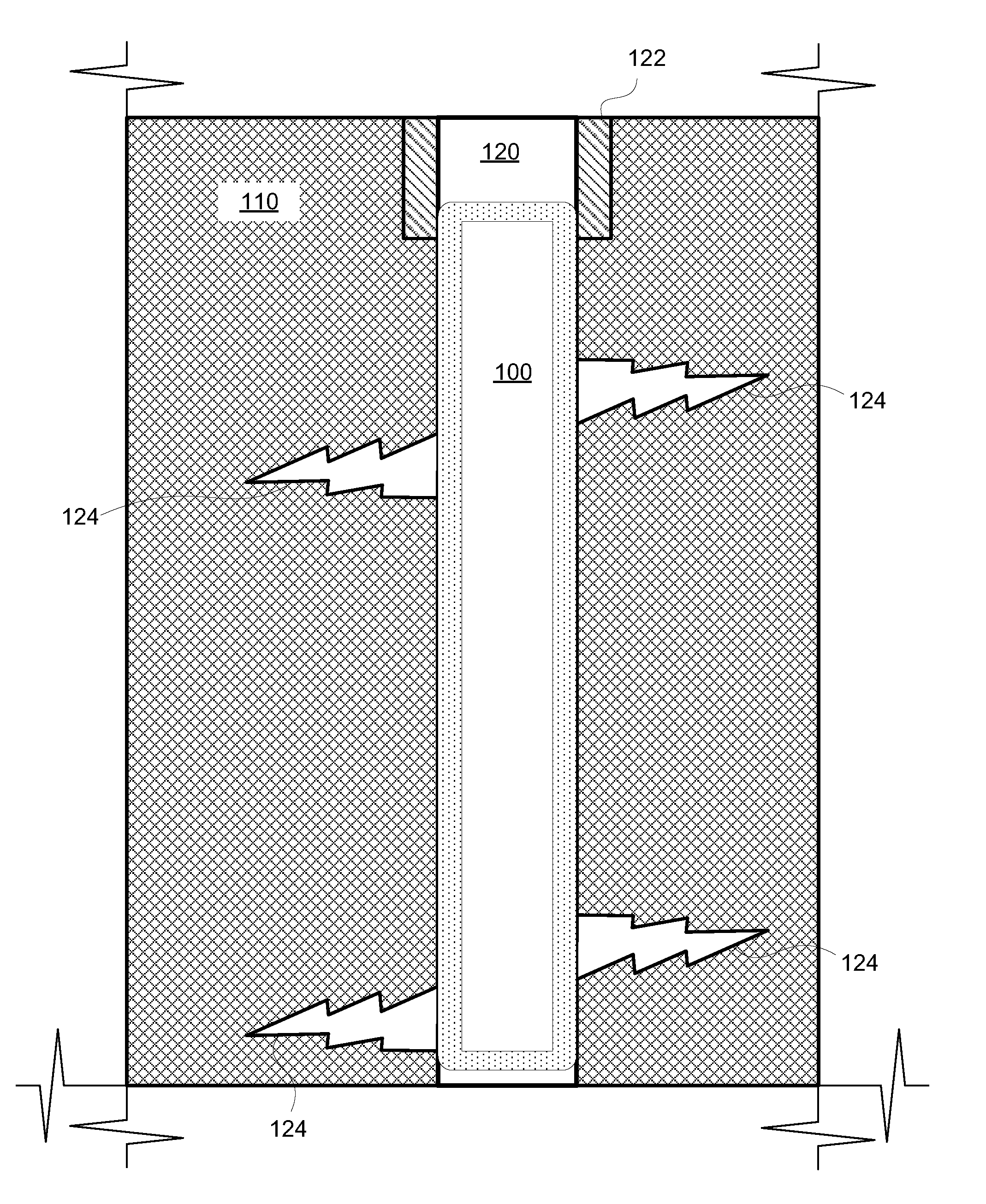
[0042] FIG. 1 shows a longitudinal cross-sectional view of an existing wellbore having fractures, and an illustrative well bladder partially installed, in accordance with some embodiments of the present disclosure;
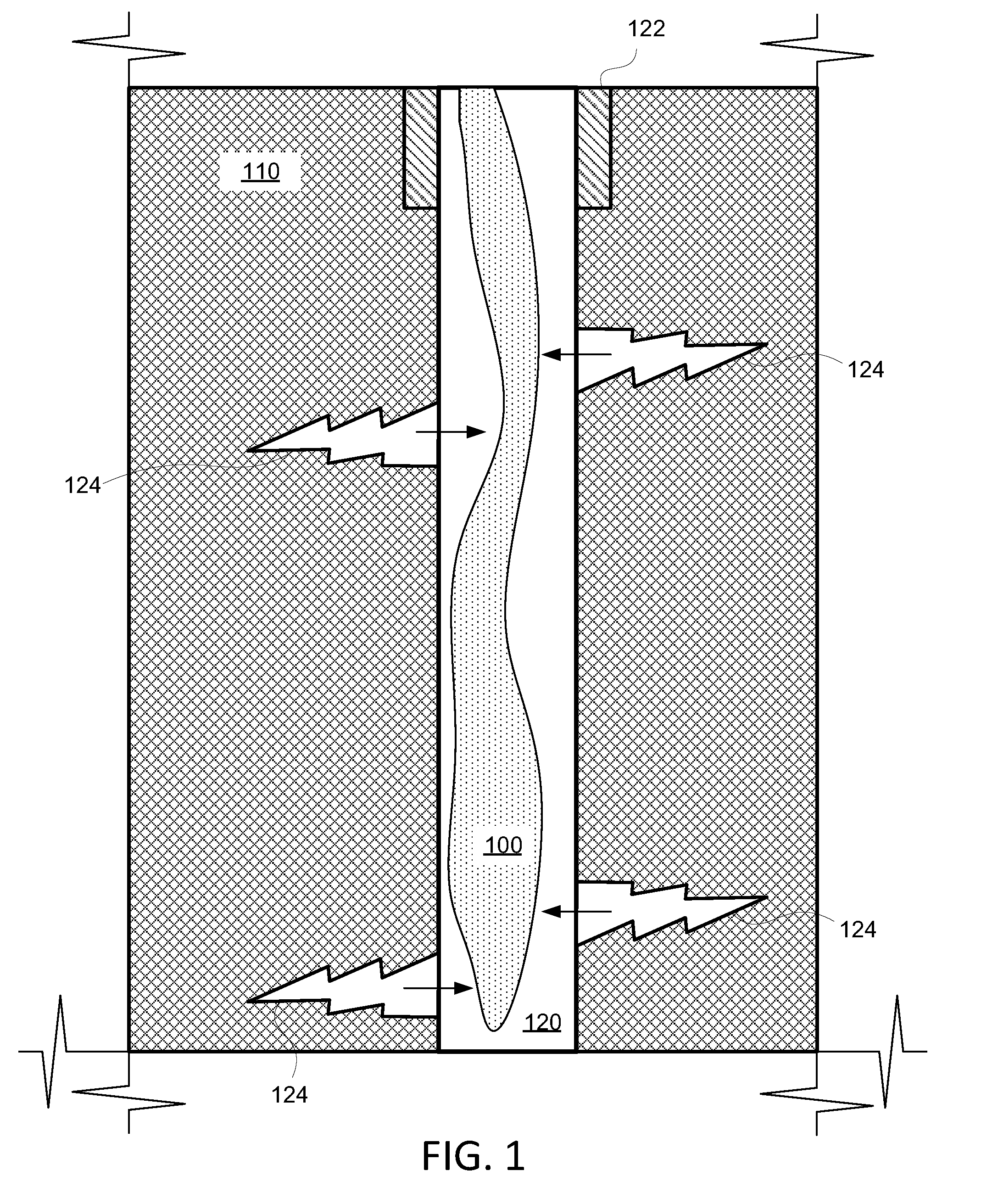
[0043] FIG. 2 shows a longitudinal cross-sectional view of the existing wellbore of FIG. 1, and an illustrative well bladder fully installed, in accordance with some embodiments of the present disclosure;
[0044] FIG. 3 shows a cross-sectional view of an illustrative well bladder, in accordance with some embodiments of the present disclosure;
[0045] FIG. 4 shows a cross-sectional view of an illustrative well bladder having two layers, in accordance with some embodiments of the present disclosure;
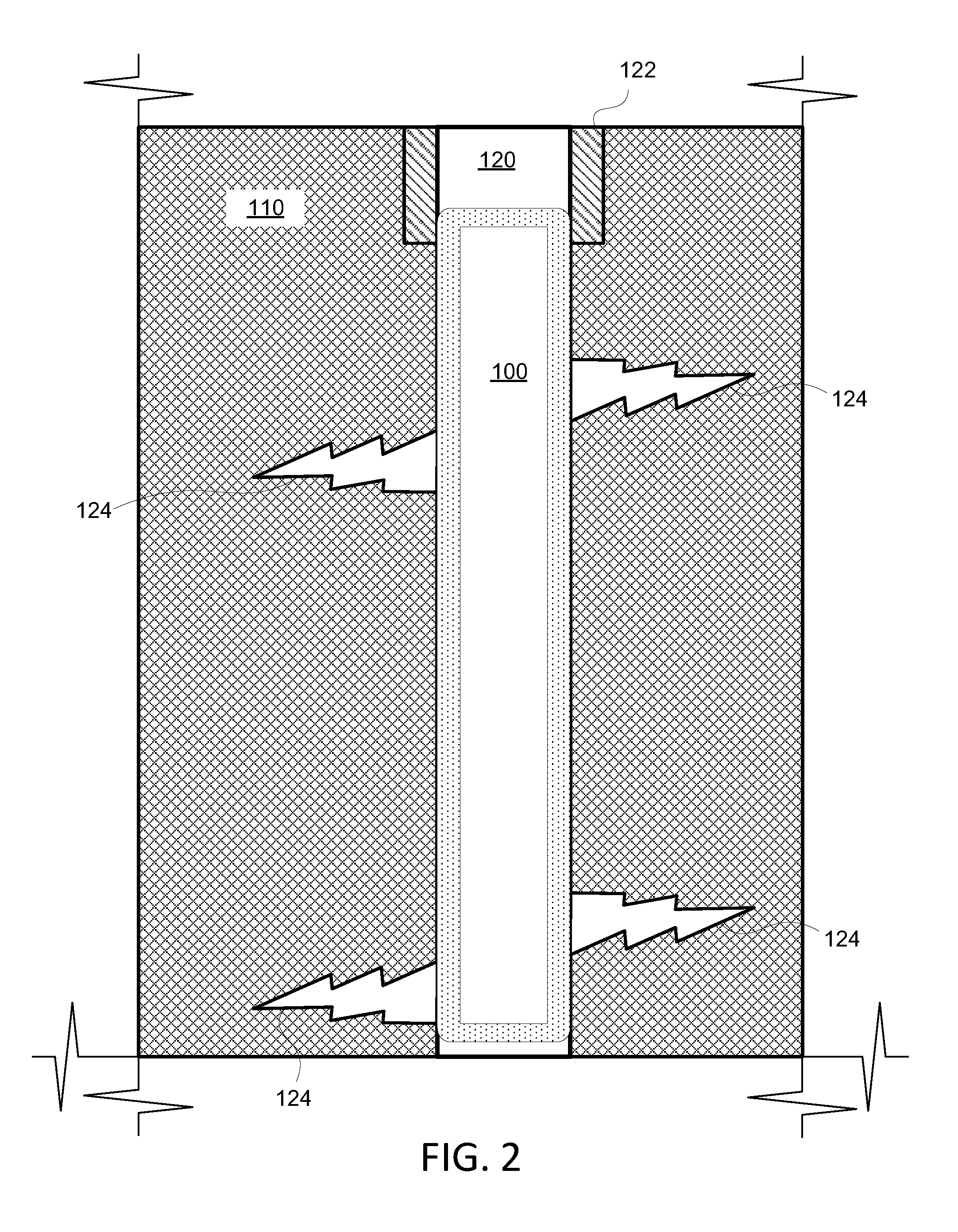
[0046] FIG. 5 shows a cross-sectional view of an illustrative well bladder having three layer-groupings, in accordance with some embodiments of the present disclosure;
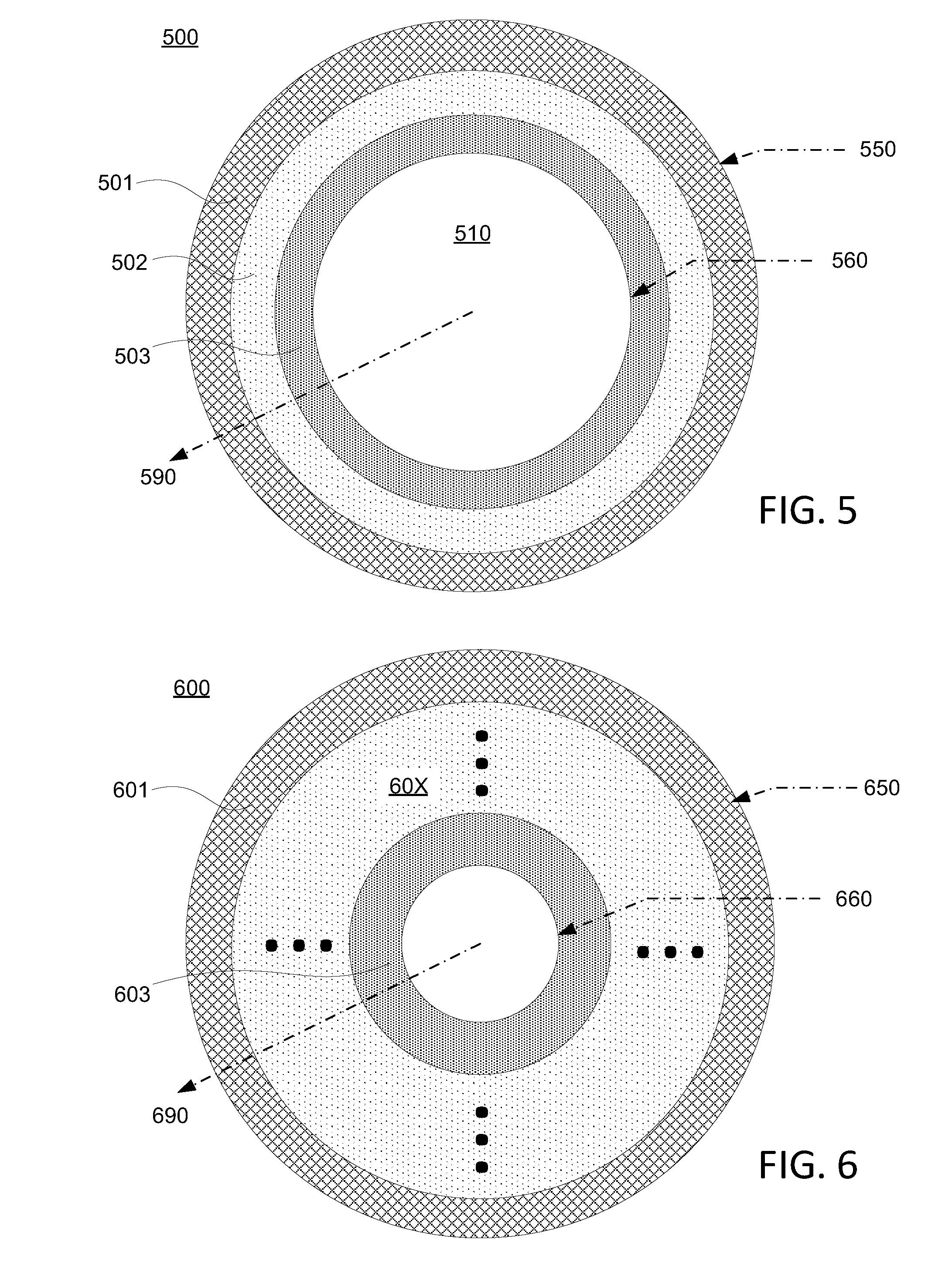
[0047] FIG. 6 shows a cross-sectional view of an illustrative well bladder having a plurality of layers, in accordance with some embodiments of the present disclosure;
[0048] FIG. 7 shows a side view of an illustrative well bladder having a single axial section, in accordance with some embodiments of the present disclosure;
[0049] FIG. 8 shows a side view of an illustrative well bladder having two axial sections, in accordance with some embodiments of the present disclosure;
[0050] FIG. 9 shows a side view of an illustrative well bladder having three axial sections, in accordance with some embodiments of the present disclosure;
[0051] FIG. 10 shows a side view of an illustrative well bladder having a plurality of sections, in accordance with some embodiments of the present disclosure;
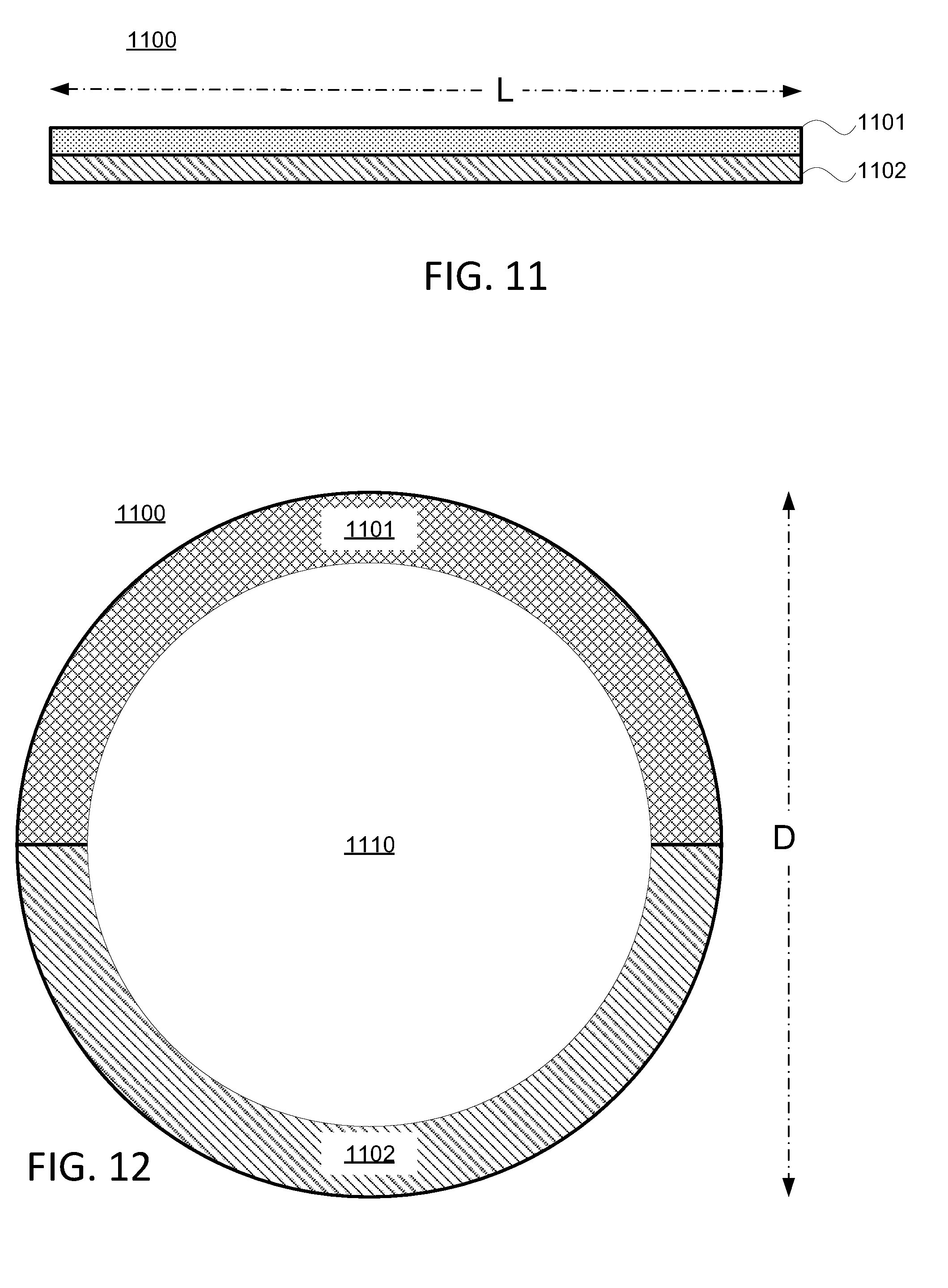
[0052] FIG. 11 shows a side view of an illustrative well bladder having two azimuthal sections, in accordance with some embodiments of the present disclosure;
[0053] FIG. 12 shows a cross-sectional view of the illustrative well bladder of FIG. 11 having two azimuthal sections, in accordance with some embodiments of the present disclosure;
[0054] FIG. 13 shows a perspective cross-sectional view of an illustrative well bladder having axial sections, azimuthal sections, and radial layers, in accordance with some embodiments of the present disclosure;
[0055] FIG. 14 shows a perspective cross-sectional view of an illustrative well bladder with reinforcement, in accordance with some embodiments of the present disclosure;
[0056] FIG. 15 shows a perspective cross-sectional view of an illustrative well bladder having internal passages, in accordance with some embodiments of the present disclosure;
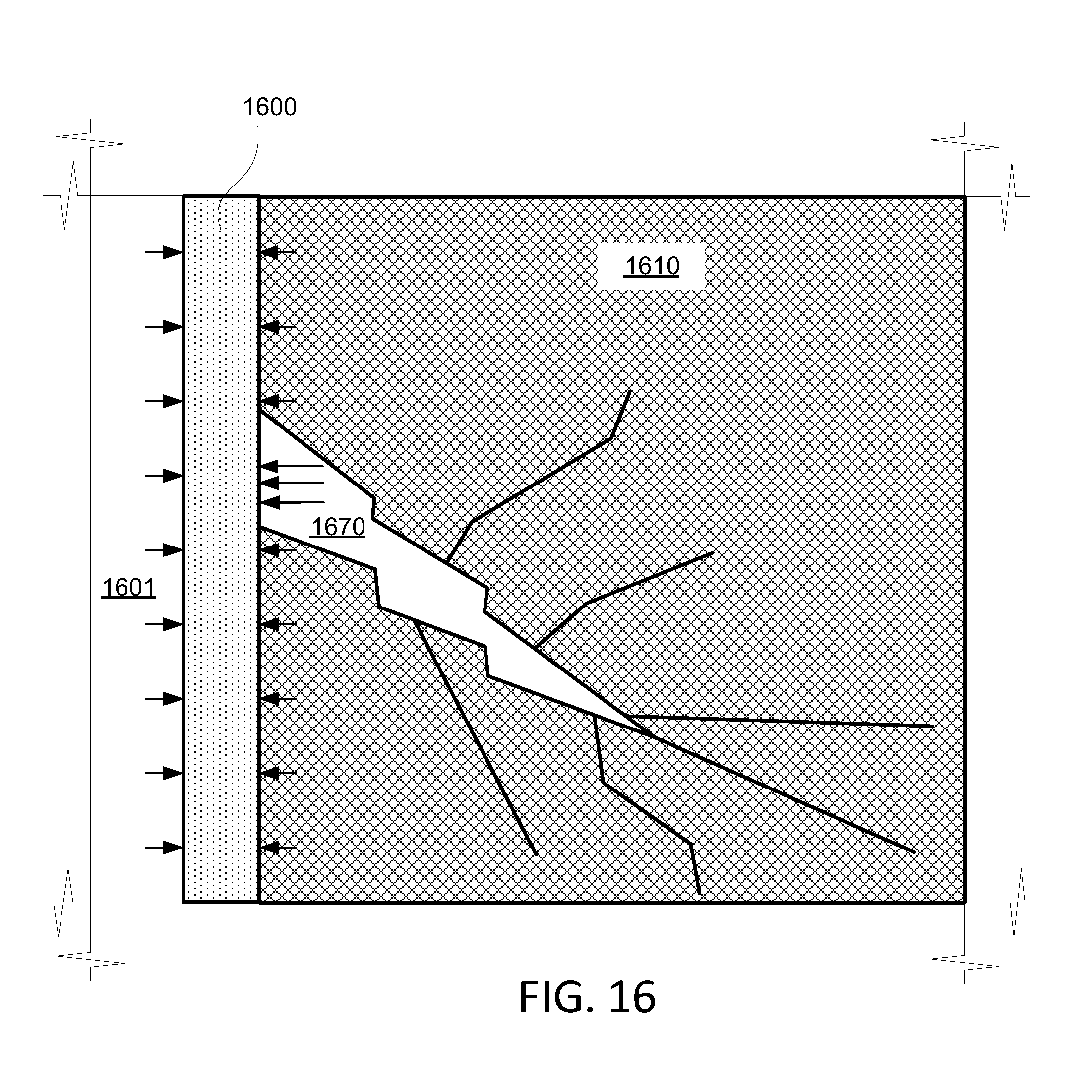
[0057] FIG. 16 shows a cross-sectional view of an illustrative well bladder installed in a wellbore exposed to internal and external forces, in accordance with some embodiments of the present disclosure;
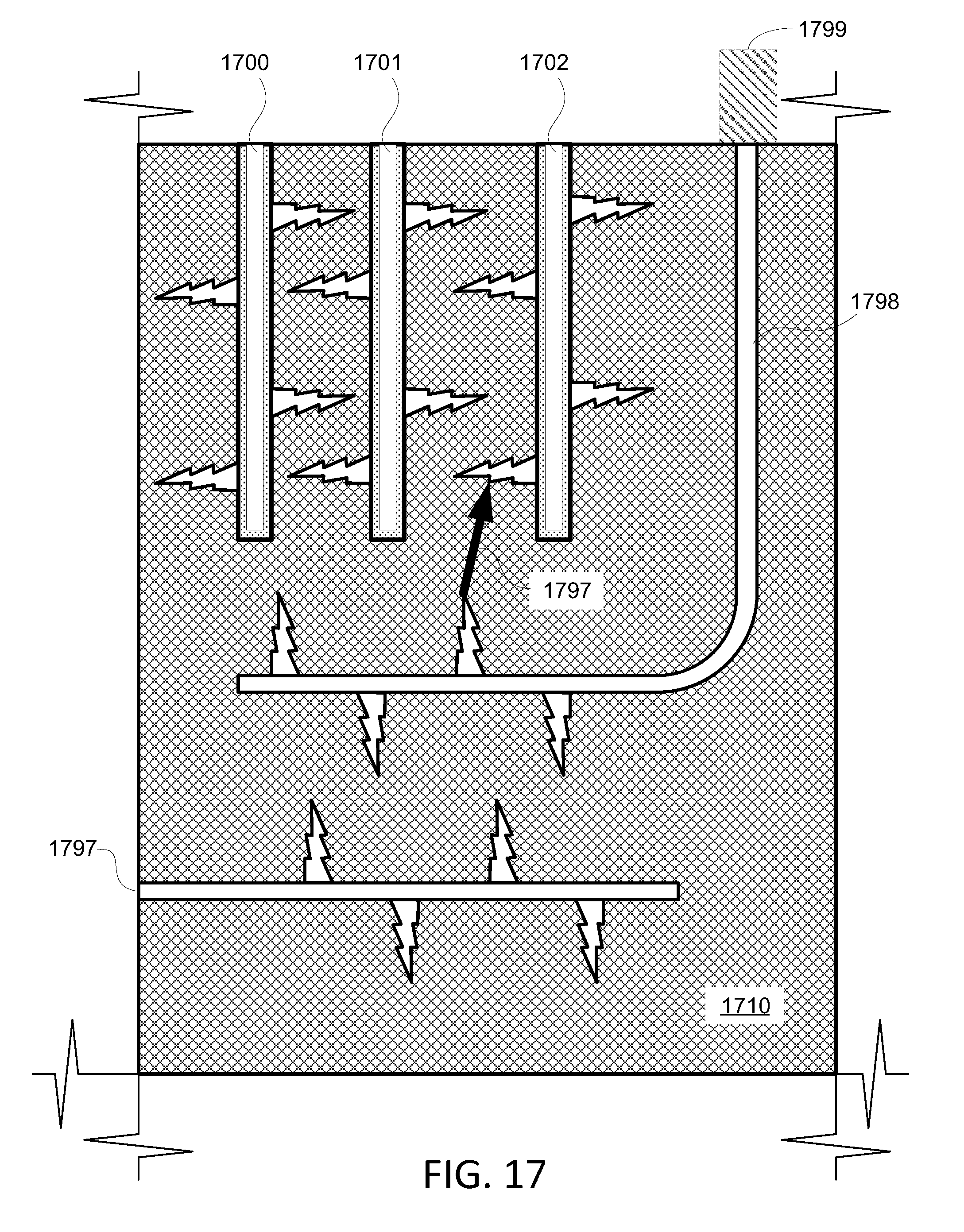
[0058] FIG. 17 shows a cross-sectional view of a producing field, and several illustrative well bladders installed in respective horizontal or vertical capped wellbores, in accordance with some embodiments of the present disclosure;
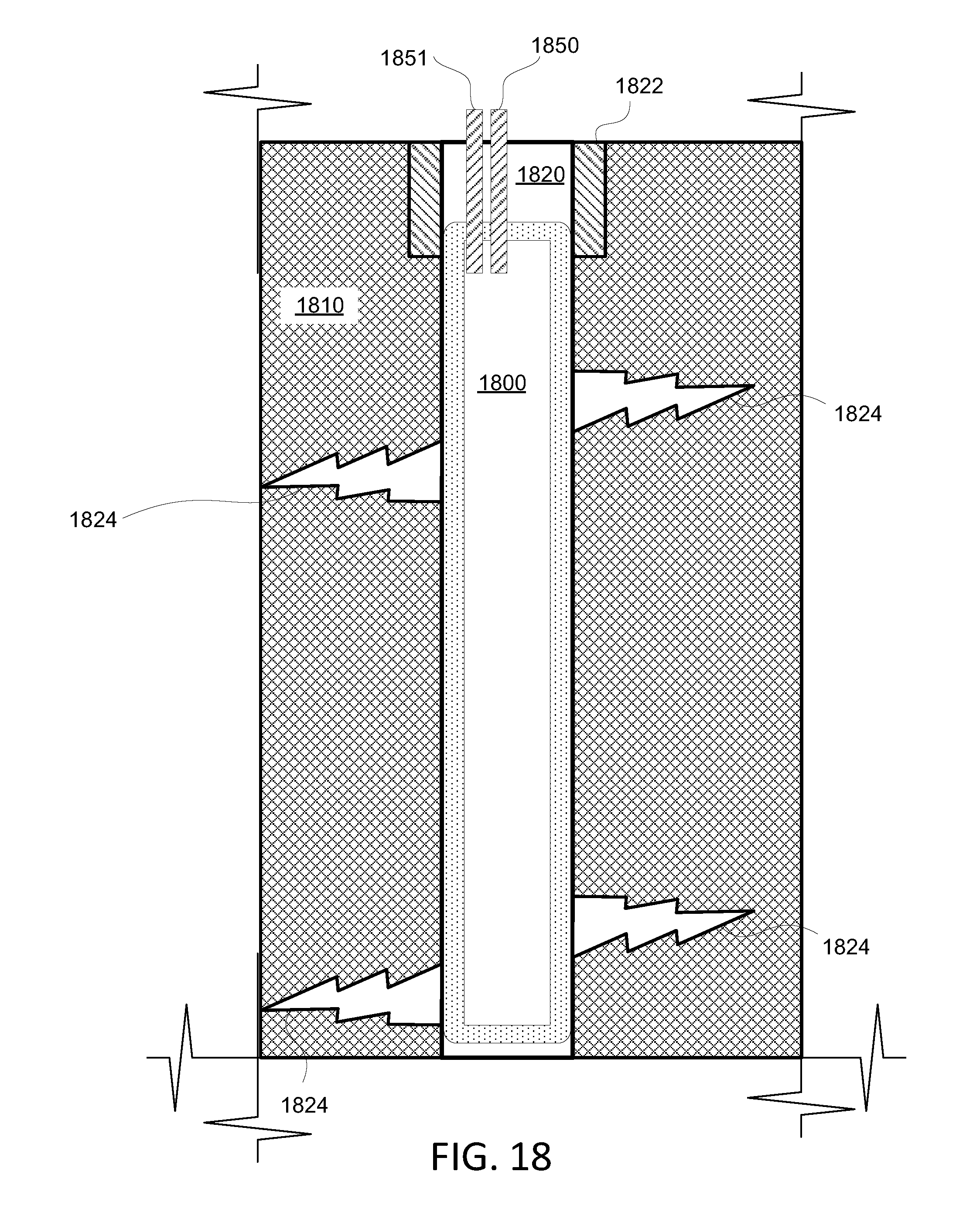
[0059] FIG. 18 shows a longitudinal cross-sectional view of an illustrative well bladder having a port and a sensor, in accordance with some embodiments of the present disclosure;
[0060] FIG. 19 shows a block diagram of an illustrative system for managing and monitoring a well bladder, in accordance with some embodiments of the present disclosure;
[0061] FIG. 20 shows a flowchart of an illustrative process for managing and monitoring a well bladder, in accordance with some embodiments of the present disclosure;
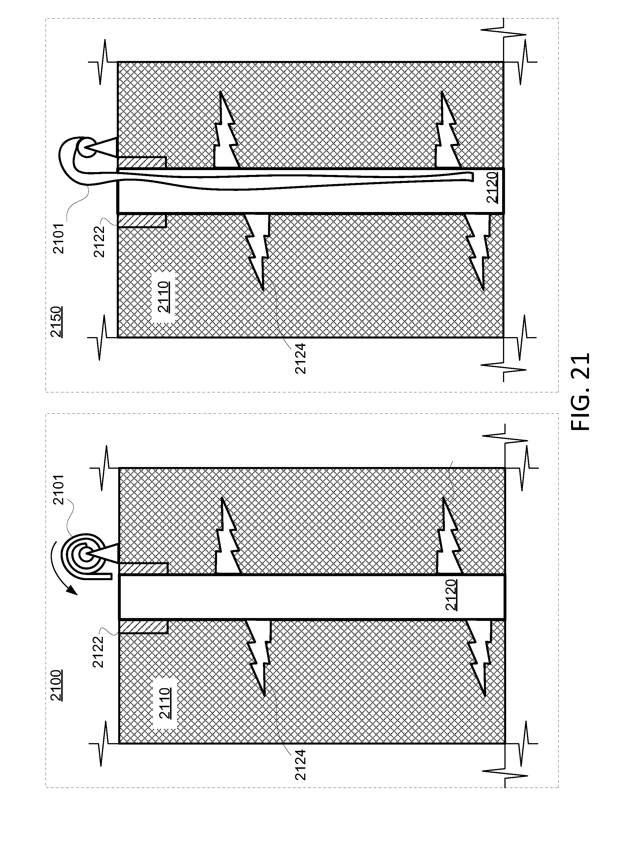
[0062] FIG. 21 shows panels of cross-sectional views of a wellbore and a spooled well bladder, in accordance with some embodiments of the present disclosure;
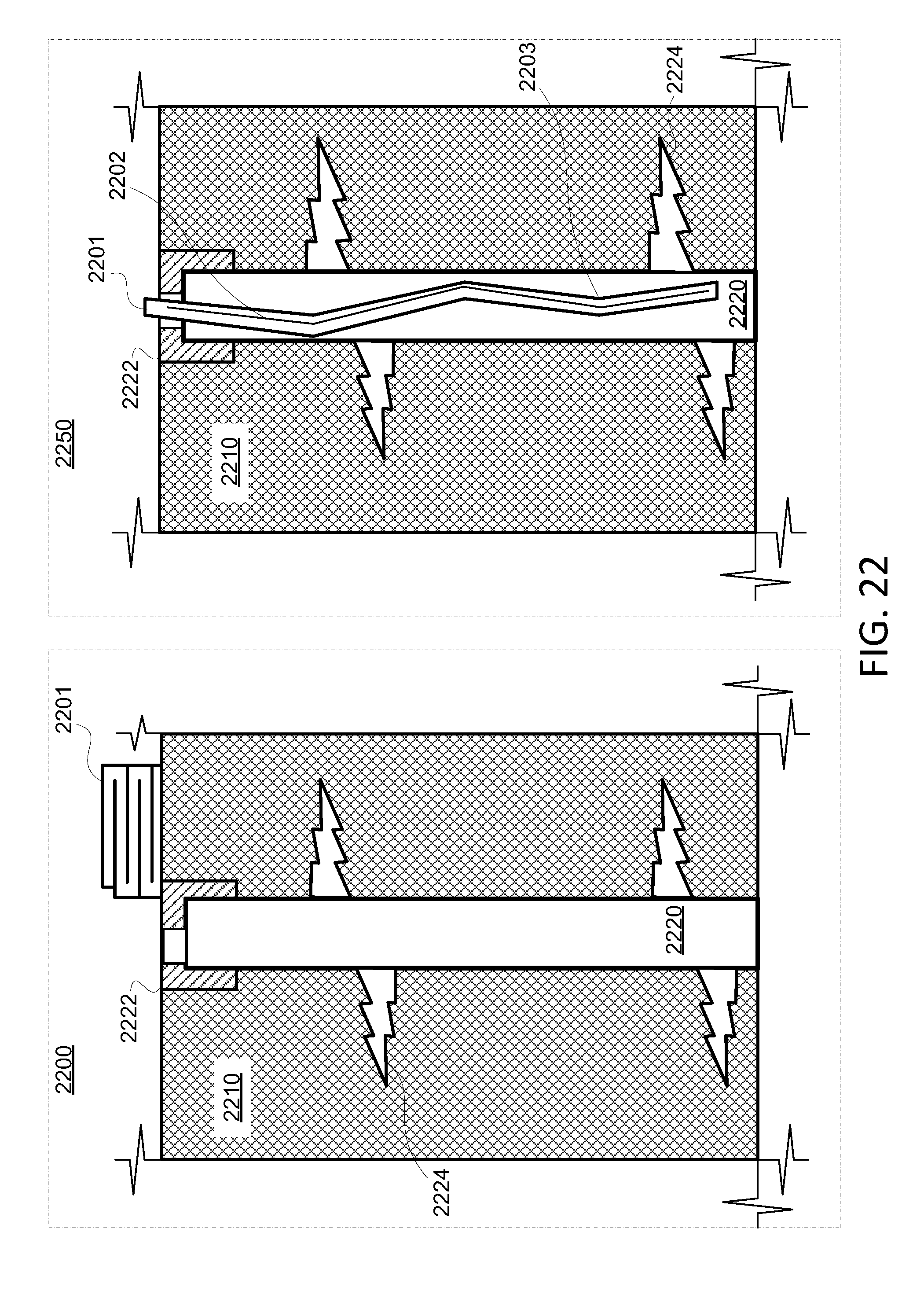
[0063] FIG. 22 shows panels of cross-sectional views of a wellbore and a folded/pleated well bladder, in accordance with some embodiments of the present disclosure;
[0064] FIG. 23 shows panels of cross-sectional views of a wellbore and a well bladder having two layers, in accordance with some embodiments of the present disclosure; and
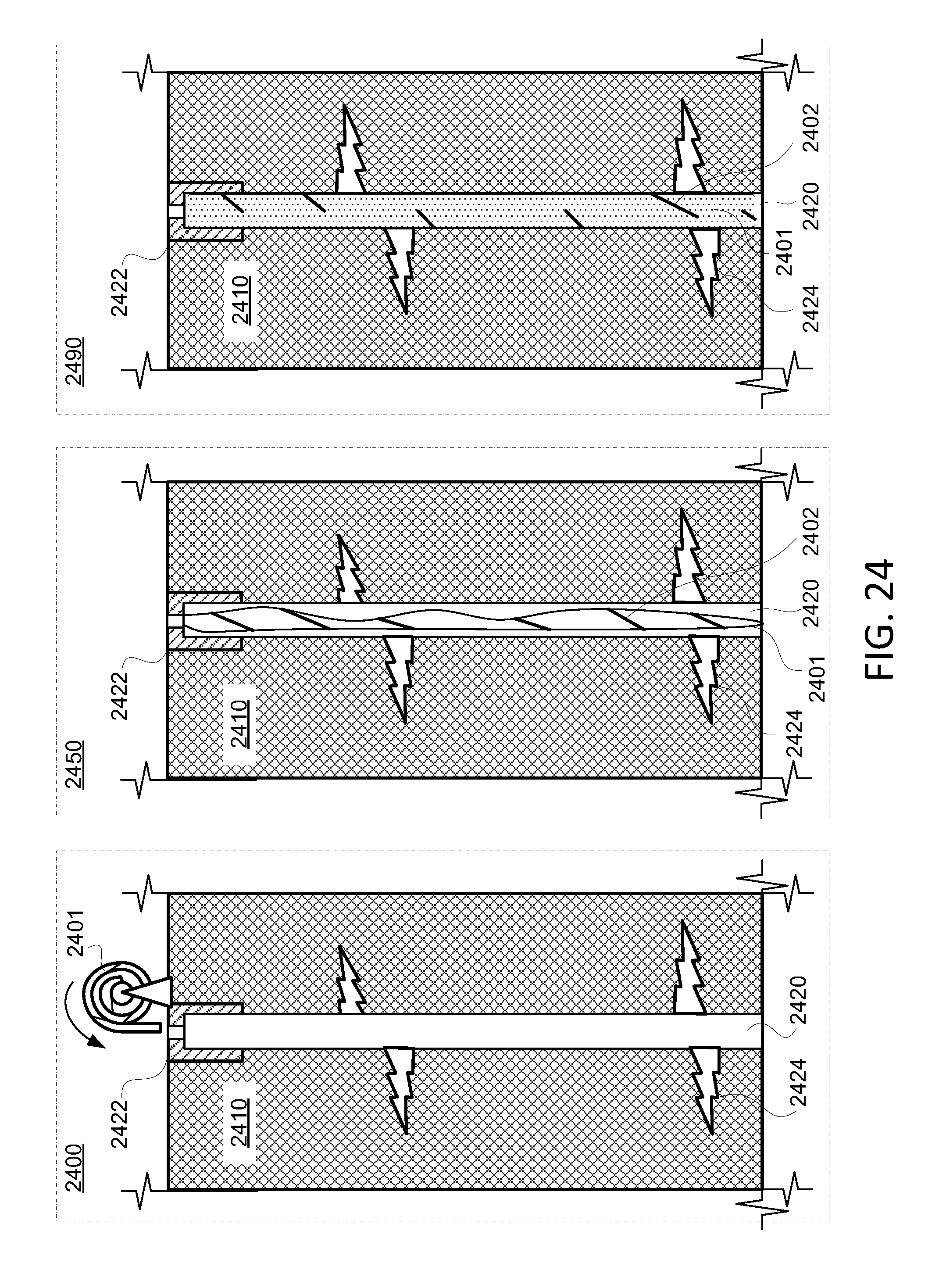
[0065] FIG. 24 shows panels of cross-sectional views of a wellbore and a well bladder having a wrap, in accordance with some embodiments of the present disclosure.
DETAILED DESCRIPTION
[0066] The present disclosure describes a bladder for sealing a wellbore from outside intrusion. For example, when drilling activities are occurring nearby, there may be an increased risk of intrusion. A well (e.g., an oil well, a gas well, a water well, a sampling well, or any other suitable well) may include a wellbore having a first section have a cement-encased pipe (e.g., a 4'' metal seamed or seamless pipe surrounded by cement to up to a 7.5'' or greater diameter), and a second section having perforations into a surrounding rock formation. The perforations may have been purposely formed to increase production of the well (e.g., by increasing effective permeability of the surrounding rock to allow more fluid to flow into the well). Fluids, or rock, may enter the wellbore via perforations, for example. Whether the wellbore is being used or not (e.g., an active well, a capped well, an abandoned well, or an inactive well), activity in surrounding rock formations may cause fluid, for example, to enter the wellbore. For example, if hydraulic fracturing were occurring nearby (e.g., within a mile or even greater), the corresponding pressure (e.g., from the fracking fluid) may force fluid into the wellbore. This may be undesirable, and may render the well unusable, require a significant cleanup effort, or introduce contamination, any or all of which can cause the well to reduce overall production or to stop producing all together. The well bladder of the present disclosure is configured to provide a seal against intrusion into a wellbore, thus allowing nearby activity to continue with reduced, or no, ill-effects in the wellbore with the well bladder. In some circumstances, for example, once activity in an adjacent well, or wells, is completed and external leaching and or leaking of external material into the protected well has been ceased, then the protecting well bladder may be removed to allow that well to continue, resume, or begin production.
[0067] FIG. 1 shows a longitudinal cross-sectional view of existing wellbore 120 having fractures 124, and illustrative well bladder 100 partially installed, in accordance with some embodiments of the present disclosure. FIG. 2 shows a longitudinal cross-sectional view of existing wellbore 120 of FIG. 1, and illustrative well bladder 100 fully installed, in accordance with some embodiments of the present disclosure. Well bladder 100 may be inserted into wellbore 120. In some embodiments, well bladder 100 may be inserted into wellbore 120 and expanded to prevent material from intruding. Well bladder 100 may be expanded (e.g., by pressurization of the interior of the bladder) in the wellbore, thus covering perforations (e.g., fractures 124) or any entrance points on the surface of wellbore 120 that connect to the surrounding reservoir. Well bladder 100 is configured to divert, or block, a fluid (e.g., oil, water, natural gas), proppant (e.g., sand, ceramic particles) or reservoir elements that could previously enter the wellbore (e.g., as shown in FIG. 1 by the arrows). With well bladder 100 expanded in wellbore 120, as shown in FIG. 2, the structural integrity of the well may be increased, and may prevent or reduce the likelihood of wellbore 120 parting if the subsurface structure suddenly shifts. The "sidewall" of a well bladder refers to the material used to give the well bladder structure and shape. For example, a sidewall may include radially stacked layers, axial sections, azimuthal sections, interior reinforcements or structures, external reinforcements, any other suitable structural components forming the bladder, or any combination thereof.
[0068] Well bladder 100 may be constructed from one or more materials, or a combination of materials, that may have, but need not have, a composite structure. For example, a bladder may be constructed from polyurethane, polyurethane composite, polyurethane with fiber (e.g., fiber reinforced), polyurethane with a foam filling, plastic, plastic composite, plastic with fiber (e.g., fiber reinforced), plastic with foam filling, rubber, rubber composite, rubber with fiber (e.g., fiber reinforced), rubber with foam filling, any other suitable material, or any combination thereof. In an illustrative example, a bladder may be constructed from a polyurethane composite, with a Kevlar fiber reinforcement. In a further illustrative example, a bladder may be constructed of a polyurethane composite, and be filled with a foam that hardens after injection into the bladder (e.g., thus creating a porous internal reinforcement in the interior of the well bladder). In some embodiments, a bladder includes one or more layers include any suitable fibers, include any suitable additives, or a combination thereof. In a further example, a well bladder may include more than one layer (e.g., an inner layer, an outer layer, and optionally one or more intermediate layers), with each layer having corresponding properties (e.g., each layer having the same or different materials).
[0069] In some embodiments, a well bladder includes two or more layers with the outer layer, inner layer, one or more intermediate layers, or any combination thereof, being made of carbon fiber fabric such as, for example, 1K, 3K, 6K, 12K, UNI carbon, Carbon/Kevlar, Carbon/Fiberglas, Carbon/Innegra, Carbon/Zylon, Caerpon/rubber, Carbon/Polyurethane, Carbon with any type of composite material, or any other suitable carbon type with or without additional material and or fabric added to it. In some embodiments, a sell bladder may include a steel mesh material of any suitable type, which may be used alone or with any other material or fabric (e.g., steel mesh with any type carbon fiber, steel mesh with any type of composite material, steel mesh with any type Kevlar, steel mesh with any type of fabric). In some embodiments, an aramid fiber material (e.g., any suitable type of meta-aramid, para-aramid such as Kevlar or Nomex or other material), including any suitable form of material (e.g., any fabric, fiber, or any other suitable form made of an aramid fiber, or any combination thereof) may be included in a well bladder. Some illustrative examples of Kevlar materials include; Kevlar K-29, Kevlar K49, Kevlar K100, Kevlar K119, Kevlar K129, Kevlar AP, Kevlar XP, and Kevlar KM2.
[0070] In some embodiments, a well bladder includes one or more layers made from a fabric (e.g., woven or non-woven material as well as knitted fabrics and netting fabrics, and technical fabrics such as Gore-Tex and Gannex). A fabric can be 100% of a particular fabric type or be a blend of two or more fabric types. A fabric may share the name of the fiber from which it is made if its content is derived entirely from the fiber (e.g., such as angora fabric made of 100% angora fiber). Although not an all-inclusive list, illustrative examples of fabrics and fabric types that can be used include: Aertex, Airdura, Airguard, Alencon lace, Antique satin, Argentan lace, Argentella lace, Armenian needlelace, Baize, Ballistic nylon, Bamboo, Banarasi sari, Ban-Lon, Barathea, Barkcloth, Batik, Batiste, Battenberg lace, Bedford cord, Bengaline silk, Beta cloth, Bobbinet, Boiled wool, Bombazine, Boucle, Braid , Brilliantine, Broadcloth, Brocade, Broderie Anglaise, Buckram, Bunting, Burano lace, Buratto lace, Burlap, C change, Calico, Cambric, Camel's hair, Camlet, Canvas, Capilene, Carbon fiber, Carrickmacross lace, Casement, Cashmere, Cavalry twill, Cedar bark, Challis, Chambray, Chantilly lace, Char cloth, Charmeuse, Charvet, Cheesecloth, Chenille, Chiengora, Chiffon, Chino, Chintz, Cloque, Cloth of gold, Conductive, Coolmax, Coir, Cordura, Corduroy, Cotton duck, Coutel, Crape (i.e., Cr pe), Cr pe-back satin, Cr pe de Chine, Cretonne, Crimplene, Crinoline, Crochet, Cotton, Damask, Darlexx, Dazzle, Delaine wool, Denim, Dimity, Dobby, Doeskin, Donegal tweed, Dotted Swiss, Double cloth, Double niting, Double weeve, Down feather , Dowlas, Drill, Drugget, Duck, Dupioni silk, Dungarees, Dyneema. Eyelet, Egyptian cotton, E-textiles, Faille, Faux fur, Felt, Filet/Lacis lace, Fishnet, Flannel, Flannelette, Fleece, Foulard, Fustian, Gabardine, Gannex, Gauze, Gazar, Georgette, Ghalamkar, Gingham, Gore-Tex, Grenadine, Grenfell Cloth, Grosgrain, Habutai, Halas lace, Haircloth, Harris Tweed, Heather knit, Hemp, Herringbone, Himroo, Hodden, Holland cloth, Hollie Point lace, Hopsack, Houndstooth check, Indian cotton, Intarsia, Interlock Jersey, Irish linen, Jacquard, Jacquard knit, Jamdani, Jersey, Jute, Jaconet, Lace, Lame, Lampas, Lantana, Lanon, Lawn cloth, Lazzer, Leather, Leatherette, Leno, Limerick lace, Linen, Linsey-woolsey, Loden, Longcloth, Loop knit, Lumalive, Mackinaw, Madapolam, Madras, Malimo, Marquisette, Matelasse, Melton, Merino, Mesh, Microfibre, Milliskin, Mockado, Mohair, Moire, Moleskin, Monk's cloth, Moquette, Mouflon, Mousseline, Muslin, Nankeen, Neoprene, Nomex, Nylonm, Net, Oilskin, Organdy, Organza, Osnaburg, Ottoman, Oxford, Omran, Paduasoy, Paisley, Panne velvet, Peau de Soie, Percale, Pique, Plisse, Plush, Point de France lace, Point de Gaze lace, Point de Venise lace, Pointelle, Polar fleece, Pongee, Poplin, Punto in Aria lace, Qiviut, Quilting, Qiana, Raschel knit, Rakematiz, Rayadillo, Rep, Reticella lace, Ribbon lace, Rib knit, Rib weave, Rinzu, Ripstop, Ripstop nylon, Russell cord, Saga Nishiki, Sailcloth, Samite, Sateen, Satin, Saye, Scarlet, Scrim, Seersucker, Serge, Shantung, Sharkskin, Shot silk, Silnylon, Smartwool, Songket, Steel mesh, Stockinette, Stub-tex, Stuff, Suede, Surah, SympaTex, Taffeta, Tais, Tammana, Tambour lace, Tapestry, Tartan, Teneriffe lace, Terrycloth, Terry velour, Ticking, Toile, Tricot knit, Tulle netting, Tussar silk, Tweed, Twill, terrywool, terrycotton, terrysilk, Ultrasuede, Velour, Velours du Kasai, Velvet, Velveteen, Venetian Lace, Venetian Wool, Ventile, Vinyl coated polyester (PVC), Viyella, Voile, Wadmal, Whipcord, Wigan, Windstopper, Worcester, Worsted wool, Youghal lace, Yarn, Zephyr, Zibeline, Zorbeez, Zoya silk, or any suitable combination thereof. A fabric may include any suitable thread count, thread density, weaving, thickness, or other suitable property. Further, a fabric may be included in any suitable form. For example, in some embodiments, a layer of a bladder includes a contiguous layer of fabric (e.g., a fabric sheet). In a further example, in some embodiments, a layer of a bladder includes strips, fibers, or otherwise portions, of fabric.
[0071] A well bladder may include a uniform or varied composition. In some embodiments, a bladder includes layers of different materials formed from different fabrics, polyurethane materials, Kevlar material, or any other suitable material blended or "sandwiched" together in one or more layers. For example, FIGS. 3-6 show cross-sectional views of illustrative well bladders.
[0072] FIG. 3 shows a cross-sectional view of illustrative well bladder 300, in accordance with some embodiments of the present disclosure. Well bladder 300 includes single layer 301, which may include a homogeneous or composite material. In some embodiments, single layer 301 includes a single, contiguous material. In some embodiments, single layer 301 includes a composite material, constructed of two or more materials interspersed or otherwise combined. In some embodiments, single layer 301 may be of anisotropic construction, having different properties in each direction (e.g., axial, radial, and azimuthal). For example, a bladder may be made of a first material, with fibers of a second material arranged to extend axially, radially, or azimuthally within the first material (e.g., a fiber-reinforcement). Well bladder 300 includes outer surface 350 configured to interface to a wellbore. Well bladder 300 includes inner surface 360 configured to interface to inner volume 310. In some embodiments, inner face 360 is configured to interface to a pressurized gas that exerts an outward force (e.g., in the radial direction along axis 390). In some embodiments, inner face 360 is configured to interface to a foam that exerts an outward force (e.g., in the radial direction along axis 390). For example, well bladder 300 may be inserted into a wellbore, and an expanding foam may be injected into inner volume 310 to expand and exert the outward force. Although shown having an inner face (e.g., inner face 360), a well bladder need not have a defined inner face. For example, a well bladder may include a porous, partitioned, or otherwise structed interior, without a well-defined inner surface.
[0073] FIG. 4 shows a cross-sectional view of illustrative well bladder 400 having two layers 401 and 402, in accordance with some embodiments of the present disclosure. In some embodiments, each layer of layers 401 and 402 includes a single, contiguous material. In some embodiments, layer 401, layer 402, or both, are constructed as composites of two or more materials. In some embodiments, one or both of layers 401 and 402 may be of anisotropic construction, having different material properties in each direction (e.g., axial, radial, and azimuthal). For example, a bladder may include a polyurethane layer (e.g., layer 402) affixed to an outer Kevlar layer (e.g., layer 401). In some embodiments, one or more materials may cross (e.g., extend across) layers 401 and 402. For example, a fiber reinforcement may be stitched between layers 401 and 402 (e.g., stitched into and through each layer). In some embodiments, layers 401 and 402 may be bonded (e.g., adhered, welded), fastened (e.g., stitched, riveted), or otherwise affixed to each other. Well bladder 400 includes outer surface 450 configured to interface to a wellbore. Well bladder 400 includes inner surface 460 configured to interface to inner volume 410. In some embodiments, inner face 460 is configured to interface to a pressurized gas that exerts an outward force (e.g., in the radial direction along axis 490). In some embodiments, inner face 460 is configured to interface to a foam that exerts an outward force (e.g., in the radial direction along axis 490). For example, well bladder 400 may be inserted into a wellbore, and an expanding foam may be injected into inner volume 410 to expand and exert the outward force. In an illustrative example of well bladder 400 of FIG. 4, layer 402 may be polyurethane, and layer 401 may be Kevlar.
[0074] FIG. 5 shows a cross-sectional view of illustrative well bladder 500 having three layer-groupings 501, 502, and 503, in accordance with some embodiments of the present disclosure. The inner layer grouping (e.g., layer 503), intermediate layer grouping (e.g., layer 502), and outer layer grouping (e.g., layer 501) may each include one or more layers. In some embodiments, well bladder 500 may include a plurality of layers, grouped into a lesser set of layer groupings, with each layer grouping including one or more layers of the plurality of layers. For example, a bladder may include an inner protective layer grouping (e.g., layer grouping 503), an intermediate layer grouping (e.g., layer grouping 502, which may be leakproof, or nearly leakproof), and an outer protective layer grouping (e.g., layer grouping 501). Each of layer groupings 501-503 may include one or more layers of any suitable material. In some embodiments, layer groupings, layers, or both, may be affixed to adjacent layers (e.g., unable to move axially, azimuthally, or radially relative to each other). In some embodiments, adjacent layers are free to slide or move relative to each other in at least one direction. A bladder may include any suitable number of layer groupings, in accordance with the present disclosure. In some embodiments, one or more materials may cross (e.g., extend across) layers 501, 502 and 503. For example, a fiber reinforcement may be stitched between layers 501, 502, and 503 (e.g., stitched into and through each layer). In some embodiments, layers 501 and 502, layers 502 and 503, or both pairs may be bonded (e.g., adhered, welded), fastened (e.g., stitched, riveted), or otherwise affixed to each other. Well bladder 500 includes outer surface 550 configured to interface to a wellbore. Well bladder 500 includes inner surface 560 configured to interface to inner volume 510. In some embodiments, inner face 560 is configured to interface to a pressurized gas that exerts an outward force (e.g., in the radial direction along axis 590). For example, well bladder 500 may be inserted into a wellbore, and a gas under pressure (e.g., a pressure greater than atmospheric pressure, an intrusion pressure, or other suitable pressure) may be introduced into inner volume 510 to expand and exert the outward force. In some embodiments, inner face 560 is configured to interface to a foam that exerts an outward force (e.g., in the radial direction along axis 590).
[0075] FIG. 6 shows a cross-sectional view of illustrative well bladder 600 having a plurality of layers, in accordance with some embodiments of the present disclosure. Layer 603 is an inner layer. Layer 601 is an outer layer. Layers 60X includes more than one layer (e.g., radially stacked). For example, well bladder 600 may include N layers having multiple layer groupings, with each layer grouping including a subset of the N layers. For example, a bladder having N layers may include two layer-groupings, each including N/2 layers, wherein N is an even integer in this example. In some embodiments, each of layers 601, 60X, and 603 includes a single, contiguous material. In some embodiments, one or more of layers 601, 60X, and 603 are constructed as composites of two or more materials. In some embodiments, one or more of layers 601, 60X, and 603 may be of anisotropic construction, having different properties in each direction (e.g., axial, radial, and azimuthal). In some embodiments, one or more materials (e.g., which may the same or different from materials of the layers) may cross the layers. For example, a fiber reinforcement may be stitched between the any or all of the layers. In some embodiments, the layers may be bonded (e.g., adhered, welded), fastened (e.g., stitched, riveted), or otherwise affixed to each other (e.g., to adjacent layers).
[0076] FIG. 7 shows a side view of illustrative well bladder 700 having single axial section 701, in accordance with some embodiments of the present disclosure. Well bladder 700 has a total length L, which may be any suitable distance, configured to follow along any suitable path (e.g., a wellbore path that may be straight or curve). For example, in some circumstances, well bladder 700 may be arranged in a relatively straight line in a wellbore. In a further example, in some circumstances, well bladder 700 may be arranged along a curved path (e.g., in a horizontally drilled well having a wellbore with at least one curved section).
[0077] FIG. 8 shows a side view of illustrative well bladder 800 having two axial sections 801 and 802, in accordance with some embodiments of the present disclosure. Well bladder 800 has a total length L, which may be any suitable distance, along any suitable path. Section 801 has length L1 and section 802 has length L2, with the sum of L1 and L2 being equal to L, the total length. Section 801 and section 802 may, but need not, include similar materials, layers, or both. For example, in some embodiments, section 801 and section 802 have the same construction, and are affixed to each other end to end (e.g., as shown in FIG. 8). In a further example, in some embodiments, section 801 and section 802 have different construction (e.g., different number of layers and/or materials), and are affixed to each other end to end (e.g., as shown in FIG. 8).
[0078] FIG. 9 shows a side view of illustrative well bladder 900 having three axial sections 901, 902, and, 903, in accordance with some embodiments of the present disclosure. Well bladder 900 has a total length L, which may be any suitable distance, along any suitable path. Section 901 has length L1, section 902 has length L2, and section 903 has length L3 with the sum of L1, L2, and L3, being equal to L, the total length. Sections 901, 902, and 903 may, but need not, include similar materials, layers, or both, as one another. For example, in some embodiments, two or more of sections 901, 902, and 903 have the same construction, and are affixed to each other end to end (e.g., as shown in FIG. 9). In a further example, in some embodiments, sections 901, 902, and 903 have different construction (e.g., different number of layers and/or materials), and are affixed to each other end to end (e.g., as shown in FIG. 9).
[0079] FIG. 10 shows a side view of an illustrative well bladder having a plurality of axial sections 1001, 100X, and 1003, in accordance with some embodiments of the present disclosure. Well bladder 1000 includes M longitudinal (i.e., lengthwise) sections, wherein M is an integer greater than 3, in accordance with the embodiments of the present disclosure. For example, section 100X includes more than one axial section. Well bladder 1000 has a total length L, which may be any suitable distance, along any suitable path. Each section has a corresponding length, with the sum of the lengths being equal to L, the total length. The sections may, but need not, include similar materials, layers, or both.
[0080] In some embodiments, a well bladder may include any suitable length. The length of the well bladder may depend on, for example, a length of the wellbore to be sealed, a distance between perforations, a material constraint, any other constraint or parameter, or any combination thereof. For example, a well bladder may have a length ranging from 100 feet long to 5000 feet long, or longer. In a further example, one or more bladders may be arranged end to end such that a series of bladders may seal a wellbore that is longer than any one bladder. In an illustrative example, a well bladder may include several axial sections, each identical to one another, and optionally affixed to each other end-to-end. Accordingly, a single design of well bladder may be modular, and may be extended axially in a discrete number of sections to adapt the length of the wellbore being sealed against intrusion.
[0081] FIG. 11 shows a side view of illustrative well bladder 1100 having two azimuthal sections 1101 and 1102, in accordance with some embodiments of the present disclosure. FIG. 12 shows a cross-sectional view of illustrative well bladder 1100 of FIG. 11 having azimuthal sections 1101 and 1102, in accordance with some embodiments of the present disclosure. A well bladder may include any suitable number of azimuthal sections, in accordance with the present disclosure. Referencing FIGS. 11-12, sections 1101 and 1102 may, but need not, include the same material, layers, or both.
[0082] In some embodiments, a well bladder may include more than one longitudinal section and more than one azimuthal section, with each section including one or more layers, in accordance with the present disclosure.
[0083] FIG. 13 shows a perspective cross-sectional view of illustrative well bladder 1300 having axial sections, azimuthal sections, and radial layers, in accordance with some embodiments of the present disclosure. Well bladder 1300 includes inner layer 1302, and an outer layer having three azimuthal sections (i.e., sections 1301, 1311, and 1321). Well bladder 1300 also includes axial sections 1313 and 1303, which are arranged axially end-to-end. Inner layer 1302 may extend along axial section 1313, both axial sections 1313 and 1303, or any suitable portion thereof. Layer 1302 includes a radially inner surface that interfaces to inner volume 1310. Inner volume 1310 is configured to house pressurized gas, pressurized liquid (e.g., water), foam, solid reinforcement (e.g., fill such as sand, plastic, rubber, or any other suitable solid), any other suitable medium that may exert an outward force and/or maintain shape, or any combination thereof.
[0084] FIG. 14 shows a perspective cross-sectional view of illustrative well bladder 1400 with reinforcement 1402, in accordance with some embodiments of the present disclosure. Well bladder 1400 as illustrated includes a single layer 1401, although any suitable number of layers and sections may be included. Reinforcement 1402 is illustrated as a spiral wound cord configured to provide a compressive force (e.g., with a component directed radially inwards) to layer 1401 to provide structural rigidity. A reinforcement may include an inner layer, an outer layer, a mesh (e.g., a netting or weave), one or more fibers (e.g., wrapped or embedded), a solid fill in inner volume 1410, any other suitable feature that provides structural rigidity or strength, or any combination thereof. A reinforcement may be integrated into one or more layers or be applied to a surface of one or more layers. For example, reinforcement 1402 may be wound around layer 1401 (e.g., from separate cord-stock), or formed as part of layer 1401 (e.g., as a spiral rib). A reinforcement may include the same material of one or more layers of a well bladder, or a different material than the well bladder.
[0085] FIG. 15 shows a perspective cross-sectional view of illustrative well bladder 1500 having internal passages 1510, in accordance with some embodiments of the present disclosure. Well bladder 1500 includes sidewall 1501 having internal passages 1510, which are configured to each include an inner volume. The portions of sidewall 1501 interior to well bladder 1500 (e.g., radially inward of the outmost portions of passages 1510) form a web, or otherwise internal structure to well bladder 1500. In some embodiments, an outer layer may be included in well bladder 1500 to seal against a wellbore, while sidewall 1501 is configured to accept pressure at inner surfaces interfacing with passages 1510. Passages 1510 may be, but need not be, axially straight and accordingly may spiral, follow a tortuous path (e.g., to form a porous well bladder), or otherwise follow a non-linear path. The sum of the inner volume corresponding to passage 1510 may be any suitable fraction of the total volume of well bladder 1500 (e.g., as determined by the outer boundary of well bladder 1500).
[0086] In some embodiments, a well bladder may be configured to compress, or fold, to within an outside diameter of between 1 to 2 inches, or greater. For example, a compressed polyurethane bladder may be passed down the bore of a seemed or un-seemed pipe having an inside diameter of 1 inch or greater (e.g., a 1'' pipe, 2'' pipe, or larger pipe).
[0087] In some embodiments, a well bladder may be configured to be expanded from a compressed state to a relatively larger outside diameter. For example, a well bladder may be folded, pleated, twisted or otherwise formed, and may be held in shape as folded, pleated, twisted or otherwise formed by an external wrap or binding. For example, a compressed bladder may be expanded by air, water, foam, any other medium capable of transmitting force, or any combination thereof, to a larger outside diameter. In an illustrative example, a well bladder may be expanded to a maximum outside diameter of 4 inches or greater. In a further example, the internal pressure of the bladder, when expanded, may be monitored (e.g., to ensure no leaks are present). In some embodiments, a well bladder may be configured to be inserted through a 1 inch pipe, or larger pipe, into a wellbore. A well bladder may be configured to be pulled out of a 1 inch pipe, or larger pipe (e.g., to be removed from a wellbore). In some embodiments, a well bladder may be completely retrievable from a wellbore (e.g., upon compressing the well bladder to a smaller outside diameter).
[0088] In some embodiments, a well bladder may have any suitable wall thickness, or wall thickness profile (e.g., a radial thickness at each axial and azimuthal position), in accordance with the present disclosure. For example, in some embodiments, a well bladder may have a corresponding wall thickness of between 0.030 inch to 0.75 inch. For example, the thickness of a well bladder may depend on an expected exterior pressure, an expected interior pressure, one or more other dimensions of the bladder, one or more dimensions of a wellbore, any other suitable parameter, or any combination thereof. For example, a thicker well bladder may be used if higher pressures are expected in surrounding rock formations (e.g., from fracking).
[0089] FIG. 16 shows a cross-sectional view of illustrative well bladder 1600 installed in a wellbore exposed to internal and external forces, in accordance with some embodiments of the present disclosure. Well bladder 1600 is expanded by pressure in inner volume 1601. External forces act on the exterior surface of well bladder 1600. For example, contact pressure from the surface of the wellbore may act radially inward on well bladder 1600 (e.g., creating a seal). In a further example, fluid pressure in fracture 1670 may act radially inward on well bladder 1600 (e.g., being sealed by the contact between well bladder 1600 and the wellbore surface). In some embodiments, a pressurized medium in inner volume 1601 pressure (e.g., gas, foam, liquid), reinforcement, or both, may be used to help well bladder 1600 maintain its shape and a seal against the wellbore.
[0090] In some embodiments, well bladder 1600 is configured to withstand the wall shear stress caused by being pressurized against fracking holes (e.g., perforations such as fracture 1670 or other openings in the wellbore) in the wellbore regardless of size of the fracking holes. For example, pressurized fluid on the outside of well bladder 1600 in an area of a few square inches may cause a local stress in the sidewall of well bladder 1600. If well bladder 1600 is not sufficiently strong, local stress may cause a nippling (e.g., local deformation) to form into interior volume 1601, fracture 1670, or both. In a further example, well bladder 1600 may hold firm and not rupture when pressed against by fluid in a 0.1 inch to 2 inch hole in a wall of the wellbore that well bladder 1600 is seated against (e.g., in an expanded state). Well bladder 1600 may be configured to withstand external pressures from adjacent fracked wells in surrounding, or nearby, rock formations. The external pressure acting on well bladder 1600 may, in some circumstances, be unknown. For example, the external pressure may be estimated to be between 500 psi to 1,000 psi typically but could be as high as 3,000 psi or possibly higher. In a further example, well bladder 1600 may be configured to withstand a maximum pressure of fluids used in hydraulic fracturing (e.g., up to 9,000 psi or greater in some instances). Well bladder 1600 may be configured to withstand internal pressures from a pressurized medium in inner volume 1601, especially in the absence of a significant external pressure.
[0091] FIG. 17 shows a cross-sectional view of a producing field 1710, and illustrative well bladders 1700, 1701, and 1702 installed in respective capped wellbores, in accordance with some embodiments of the present disclosure. Field 1710 includes unused wellbores into which respective well bladders 1700, 1701, and 1702 are installed. Field 1710 also includes active wells 1797 and 1798. For example, active well 1798 may be a horizontal-drilled oil well undergoing hydraulic fracturing (e.g., from processing system 1799). Increased pressure in formations of field 1710 may increase the likelihood of intrusion of fracking fluid into the inactive wellbores (e.g., as shown illustratively by arrow 1797). Well bladders 1701-1703 are configured to prevent intrusion in the respective wellbores from activity in wellbores 1797 and 1798.
[0092] In some embodiments, a well bladder may include fittings, components, sensors, any other components, or any combination thereof that may be used during installation, use, monitoring, removal, or a combination thereof. For example, in some embodiments, a well bladder end connection(s) may be configured to support a type of device it will be attached to. In some embodiments, for example, the bottom of the well bladder is constricted as to be able to be threaded through the well piping and be able to support the required expansion and pressures when in full use. In some embodiments, the bladder can be weighted if needed. Two or more well bladders may also be able to be coupled together by end fittings to extend the overall length of the effective bladder as necessary.
[0093] FIG. 18 shows a longitudinal cross-sectional view of illustrative well bladder 1800 having port 1850 and sensor 1851, in accordance with some embodiments of the present disclosure. Port 1850 is configured to allow fluid (e.g., gas, liquid, slurry, foam), or any other suitable material, to be added or removed from the inner volume of well bladder 1800. In some embodiments, port 1850 may be used during installation to expand well bladder 1800 to seal against wellbore 1820. In some embodiments, port 1850 may be used after installation to maintain the seal against wellbore 1820. Sensor 1851 is configured to sense one or more properties of well bladder 1800 during installation, after installation, during removal, or a combination thereof. For example, sensor 1851 may include a pressure sensor (e.g., a piezoelectric sensor, a strain-gage based sensor), a flow sensor (e.g., to determine a total volume), a chemical sensor (e.g., configured to detect a constituent of intruding fluid, or the fluid used to pressurize the inner volume), a strain sensor (e.g., configured to sense strain in the sidewall of well bladder 1800), any other suitable sensor or any combination thereof. In an illustrative example, well bladder 1800 may include one or more end fittings configured to accommodate sensor 1851, port 1850, or both.
[0094] FIG. 19 shows a block diagram of illustrative system 1900 for managing and monitoring a well bladder, in accordance with some embodiments of the present disclosure. System 1900 including control circuitry 1910, sensors 1951, and auxiliary system 1950, in accordance with some embodiments of the present disclosure. Control circuitry 1910 may include a processor 1912, communication hardware 1914 ("COMM"), memory 1916, and power supply 1918.
[0095] Control circuitry 1910 may include hardware, software, or both, implemented on one or more modules configured to provide control, monitoring, or both, of a well bladder system. In some embodiments, processor 1912 may include one or more microprocessors, microcontrollers, digital signal processors, programmable logic devices, field-programmable gate arrays (FPGAs), application-specific integrated circuits (ASICs), etc., and may include a multi-core processor. In some embodiments, processor 1912 may be distributed across multiple separate processors or processing units, for example, multiple of the same type of processing units or multiple different processors. In some embodiments, control circuitry 1910 may execute instructions stored in memory for managing a well bladder system. Memory 1916 may be an electronic storage device that is part of control circuitry 1910. For example, memory may be configured to store electronic data, computer software, or firmware, and may include random-access memory, read-only memory, hard drives, optical drives, solid state devices, or any other suitable fixed or removable storage devices, and/or any combination of the same. Nonvolatile memory may also be used (e.g., to launch a boot-up routine and other instructions).
[0096] In some embodiments, control circuitry 1910 may be powered by power supply 1918. Power supply 1918 may include, for example, a battery, an AC power supply (e.g., receiving power from an AC grid), a DC power supply (e.g., a DC-AC inverter configured to rectify and regulate AC power), any other power supply, any corresponding components (e.g., terminals, switches, fuses, and cables), or any combination thereof In some embodiments, power supply 1918 may supply power to sensors 1951, auxiliary system 1950, any other suitable systems or components, or any combination thereof.
[0097] Sensor(s) 1951 may include one or more pressure sensors, flow sensors, chemical sensors, strain sensors, any other suitable sensors, or any combination thereof. For example, sensor 1951 may include a pressure sensor powered by power supply 1918 and configured to provide a sensor signal to control circuitry 1910. The pressure sensor may be configured to sense a pressure of an inner volume of a well bladder. In a further example, sensor 1951 may include a chemical sensor configured to detect a constituent of intrusion fluid. A chemical sensor may include an optical sensor (e.g., for spectral absorption measurements, or other optical measurements), an electrochemical sensor (e.g., for detecting gaseous or liquid electrochemically-active species), any other suitable chemical sensor, or any combination thereof. In some embodiments, sensor 1951 includes a probe, sampling system, or other components for performing sensing. For example, sensor 1951 may include a gas sampling system, a liquid or gas chromatograph, and an electronic output coupled to control circuitry 1910.
[0098] Auxiliary system 1950 may include a fluid pressurization system that is controlled by control circuitry 1910. For example, auxiliary system 1950 may include a gas compressor system configured to pressurize a gas for pumping into an inner volume of a well bladder. In a further example, auxiliary system 1950 may include a liquid pump system configured to pressurize a liquid for pumping into an inner volume of a well bladder. In a further example, auxiliary system 1950 may include a hardening-foam dispensing system configured to generate and handle a foam for pumping into an inner volume of a well bladder.
[0099] FIG. 20 shows a flowchart of an illustrative process for managing and monitoring a well bladder, in accordance with some embodiments of the present disclosure. At least some steps of illustrative process 2000 may be performed by illustrative system 1900 of FIG. 19, for example.
[0100] Step 2002 includes inserting and configuring a well bladder in a wellbore. In some embodiments, configuring the well bladder includes selecting one or more well bladder materials. In some embodiments, configuring the well bladder includes selecting one or more well bladder sizes (e.g., outer diameters, lengths, number of sections, reinforcement). Inserting the well bladder in the wellbore may include, for example, unfolding (e.g., at folds or pleats), unrolling, pushing, or otherwise arranging the well bladder in the wellbore for subsequent expansion. For example, a well bladder may include pleating, wrapping (e.g., shrink wrapping), rolling, compaction, compression, any other suitable reduction of size, or any combination thereof. In a further example, the reduced well bladder may be secured in the reduced state (e.g., by tying, cinching, or otherwise constraining from expanding), and allowed to unfold, unroll, or otherwise expand, when pressurized (e.g., a pressurized medium add provided to the inner volume). In some embodiments, the size-reduced well bladder is threaded down the wellbore and then allowed to expand sufficiently to protect the wellbore from intrusion due to external pressure (e.g., from fracking nearby). For example, the well bladder may be reduced in size by rolling, and arranged in a long pipe, which is inserted into the wellbore. The pipe may then be removed leaving reduced well bladder in the wellbore, to be subsequently expanded. In some embodiments, a rod arranged inside of the well bladder (e.g., in the inner volume) may be used to push the well bladder into the wellbore. For example, the rod may then be removed from the well bladder and the well bladder may be subsequently expanded. In a further example, the rod may be hollow and coupled to a port and may be used to provide a pressurized medium to expand the well bladder (e.g., the rod may but need not remain fully in place axially during expansion). In some embodiments, the end of the well bladder may be weighted to aid in inserting the well bladder (e.g., for a vertical wellbore). In some embodiments, a pressurized medium may be used to aid in inserting the well bladder in the wellbore. For example, a pressurized gas may be used to unfurl an internal passage of the well bladder (e.g., the inner volume or a different internal passage) to cause the well bladder to axially insert into the wellbore.
[0101] In some embodiments, the well bladder has outer dimensions that correspond, when expanded, to the size of a wellbore. For example, the outer diameter of an expanded well bladder that is free of the wellbore may be slightly larger than the wellbore (e.g., in terms of diameter or volume), such that is presses against the wellbore when arranged in the wellbore and expanded. In some embodiments, the length of the well bladder may be such that the well bladder extends axially along the entire wellbore or a portion of the wellbore (e.g., an axial section having fractures).
[0102] Step 2004 includes pressurizing an inner volume of the well bladder when the well bladder is arranged in the wellbore. In some embodiments, system 1900 is configured to apply pressure to the inner volume. In some embodiments, pressurizing the inner volume includes reaching a pressure threshold in the inner volume, thus causing at least a minimum sealing force against the wellbore. In an illustrative example, system 1900 may include auxiliary system 1950 configured to pressurize the inner volume. In some embodiments, step 2004 includes opening a valve. For example, the well bladder may include a port coupled to a valve, and system 1900 causes the valve to open to provide the pressurized medium. In some embodiments, step 2004 includes closing the valve, after the well bladder is sufficiently pressurized. For example, if the pressure, or other suitable property, of the well bladder exceeds a threshold (e.g., the pressure in the inner volume reaches a threshold pressure), then system 1900 may close the valve to seal the well bladder.
[0103] Step 2006 includes monitoring one or more properties of the well bladder. In some embodiments, control circuitry 1910 is configured to sense, measure, or otherwise determine one or more properties of the well bladder based on input from one or more sensors 1951. For example, in some embodiments, control circuitry 1910 is configured to monitor a pressure of the inner volume of the well bladder over time. Changes in the monitored pressure may indicate a leak out (e.g., the pressure decreases, or the well bladder has ruptured), a leak in (e.g., the pressure increases), nearby fracking activity (e.g., the pressure increases around the exterior of the well bladder), damage to at least a portion of the well bladder or sensor, or a combination thereof.
[0104] Step 2008 includes adjusting one or more properties of the well bladder. In some embodiments, control circuitry 1910 is configured to increase, decrease, or otherwise change one or more properties of the well bladder. In some embodiments, control circuitry 1910 may perform step 2008 in response to step 2006. For example, in some embodiments, control circuitry 1910 is configured to monitor a pressure of the inner volume of the well bladder over time and adjust the pressure to remain within a predetermined range. In some embodiments, for example, system 1900 is configured to maintain the pressure in the inner volume above a threshold. In some embodiments, system 1900 may repeat steps 2006 and 2008 to maintain a sealed wellbore to prevent intrusion.
[0105] FIG. 21 shows panels 2100 and 2150 of cross-sectional views of wellbore 2120 and a spooled well bladder 2101, in accordance with some embodiments of the present disclosure. Panel 2100 illustrates well bladder 2101 spooled, and not installed in wellbore 2120. Panel 2150 illustrates well bladder 2101 unspooled and arranged in wellbore 2120. For example, as shown in panel 2150, an inner volume of well bladder 2101 may be subsequently pressurized to seal against fractures 2124 into rock 2110 to seal wellbore 2120 from intrusion. In some embodiments, when well bladder 2101 is to be removed from wellbore 2120 (e.g., after nearby activity has stopped or wellbore 2120 is to be productive), well bladder 2101 may be de-pressurized and re-spooled. In some embodiments, wellbore head 2122 includes an opening, a fitting, a port, any other suitable passage open to wellbore 2120, or any combination thereof to allow well bladder 2101 to be arranged in wellbore 2120 and be removed from wellbore 2120.
[0106] FIG. 22 shows panels 2200 and 2250 of cross-sectional views of wellbore 2220 and folded/pleated well bladder 2201, in accordance with some embodiments of the present disclosure. Panel 2200 illustrates well bladder 2201 folded and pleated, and not installed in wellbore 2220. Panel 2250 illustrates well bladder 2101 unfolded (e.g., to expand folds and pleats) and arranged in wellbore 2220. For example, as shown in panel 2250, an inner volume of well bladder 2201 may be subsequently pressurized to seal against fractures 2224 into rock 2210 to seal wellbore 2220 from intrusion. In some embodiments, when well bladder 2201 is to be removed from wellbore 2220 (e.g., after nearby activity has stopped or wellbore 2220 is to be productive), well bladder 2201 may be de-pressurized and optionally re-folded along the folds and pleats (e.g., pleat 2202 and fold 2203). In some embodiments, wellbore head 2222 includes an opening, a fitting, a port, any other suitable passage open to wellbore 2220, or any combination thereof to allow well bladder 2201 to be arranged in wellbore 2220 and be removed from wellbore 2220.
[0107] FIG. 23 shows panels 2300, 2350, and 2390 of cross-sectional views of wellbore 2320 and well bladder 2301 having two layers 2301 and 2302, in accordance with some embodiments of the present disclosure. Panel 2300 illustrates well bladder 2301 being threaded into wellbore 2320. Panel 2350 illustrates well bladder 2301 arranged in wellbore 2320. For example, as shown in panel 2350, an inner volume of well bladder 2301 may be subsequently pressurized to seal against fractures 2324 into rock 2310 to seal wellbore 2320 from intrusion. Panel 2390 shows inner layer 2302 arranged on the inside of layer 2301 (i.e., the layers in this example are not affixed to each other). Layer 2302 is configured to be pressurized by a pressurized medium and is configured to apply contact pressure to layer 2301, forcing layer 2301 against fractures 2324 and wellbore 2320 to create a seal. For example, layer 2302 may include a polyurethane material (e.g., for fluid-tightness), and layer 2301 may include a Kevlar material (e.g., for strength). In some embodiments, wellbore head 2322 includes an opening, a fitting, a port, any other suitable passage open to wellbore 2320, or any combination thereof to allow layers 2301 and 2302 to be arranged in wellbore 2320 and be removed from wellbore 2320.
[0108] FIG. 24 shows panels 2400, 2450, and 2490 of cross-sectional views of wellbore 2420 and well bladder 2401 having wrap 2402, in accordance with some embodiments of the present disclosure. Panel 2400 illustrates well bladder 2401 on a spool outside of wellbore 2420. Panel 2450 illustrates well bladder 2401, with wrap 2402 maintaining a compaction in size, arranged in wellbore 2420. For example, as shown in panel 2450, an inner volume of well bladder 2401 may be subsequently pressurized to seal against fractures 2424 into rock 2410 to seal wellbore 2420 from intrusion. Panel 2490 shows well bladder 2401 while pressurized, with wrap 2402 released (e.g., wrap 2402 is broken by tensile stress from expansion of well bladder 2401 as illustrated). Well bladder 2401 is configured to be pressurized by a pressurized medium and is configured to apply contact pressure to wrap 2402, forcing wrap 2402 to expand, rupture, or both, as well bladder 2401 seals against fractures 2324 and wellbore 2320. In some embodiments, wellbore head 2422 includes an opening, a fitting, a port, any other suitable passage open to wellbore 2420, or any combination thereof to allow well bladder 2401 to be arranged in wellbore 2420 and be removed from wellbore 2420. In some embodiments, for example, well bladder 2401 may be twisted instead of, or in addition to, being rolled, prior to being arranged in wellbore 2420.
[0109] Wrap 2402 may be a fiber, a mesh, a shrink wrap, any other suitable wrapping or binding, or any combination thereof. In some embodiments, for example, shrink wrap may be applied to all or some of the well bladder for installation. For example, once installed, upon pressurizing the well bladder (e.g., causing expansion), the shrink wrap material will fall away (e.g., split, tear, or otherwise stop binding or compressing the well bladder).
[0110] While the well bladders of the present disclosure are provided in the context of an oil fracking well, it will be understood that a well bladder can be applied in any suitable context, including a gas well, a liquid well (e.g., to prevent contaminants from entering a water supply), any other suitable well, or any combination thereof. It will also be understood that the present disclosure may be applied to a well having any suitable orientation including a vertical well, a horizontal well, or a well having both vertical and horizontal sections.
[0111] The foregoing is merely illustrative of the principles of this disclosure and various modifications may be made by those skilled in the art without departing from the scope of this disclosure. The above described embodiments are presented for purposes of illustration and not of limitation. The present disclosure also can take many forms other than those explicitly described herein. Accordingly, it is emphasized that this disclosure is not limited to the explicitly disclosed methods, systems, and apparatuses, but is intended to include variations to and modifications thereof, which are within the spirit of the following claims.
* * * * *
D00000
D00001
D00002
D00003
D00004
D00005
D00006
D00007
D00008
D00009
D00010
D00011
D00012
D00013
D00014

D00015
XML
uspto.report is an independent third-party trademark research tool that is not affiliated, endorsed, or sponsored by the United States Patent and Trademark Office (USPTO) or any other governmental organization. The information provided by uspto.report is based on publicly available data at the time of writing and is intended for informational purposes only.
While we strive to provide accurate and up-to-date information, we do not guarantee the accuracy, completeness, reliability, or suitability of the information displayed on this site. The use of this site is at your own risk. Any reliance you place on such information is therefore strictly at your own risk.
All official trademark data, including owner information, should be verified by visiting the official USPTO website at www.uspto.gov. This site is not intended to replace professional legal advice and should not be used as a substitute for consulting with a legal professional who is knowledgeable about trademark law.