Sealed Tabbed Asphalt Shingle System And Method
Strickland; Chad
U.S. patent application number 15/823815 was filed with the patent office on 2019-05-30 for sealed tabbed asphalt shingle system and method. The applicant listed for this patent is Chad Strickland. Invention is credited to Chad Strickland.
| Application Number | 20190161970 15/823815 |
| Document ID | / |
| Family ID | 66634967 |
| Filed Date | 2019-05-30 |


| United States Patent Application | 20190161970 |
| Kind Code | A1 |
| Strickland; Chad | May 30, 2019 |
SEALED TABBED ASPHALT SHINGLE SYSTEM AND METHOD
Abstract
A sealed tabbed asphalt shingle system and method of sealing around the slots defining the tabs of the installed shingles, prevent the intrusion of water and preventing the lifting of installed shingles by wind forces.
| Inventors: | Strickland; Chad; (Many, LA) | ||||||||||
| Applicant: |
|
||||||||||
|---|---|---|---|---|---|---|---|---|---|---|---|
| Family ID: | 66634967 | ||||||||||
| Appl. No.: | 15/823815 | ||||||||||
| Filed: | November 28, 2017 |
| Current U.S. Class: | 1/1 |
| Current CPC Class: | E04D 1/26 20130101; E04D 2001/005 20130101; E04D 1/36 20130101; E04D 2001/3435 20130101 |
| International Class: | E04D 1/36 20060101 E04D001/36; E04D 1/26 20060101 E04D001/26 |
Claims
1. A sealed tabbed asphalt shingle system for shingles having top and bottom faces, upper and lower areas when installed, and tabs in the lower areas defined by slots having a closed end, two parallel legs, and an open end, and a granular coating on the top face, the sealed tabbed asphalt shingle comprising: a sealant layer formed in a U-shaped configuration extending from immediately above the closed end and along two parallel legs of each slot on the bottom face of each shingle; where, in use, upon installation, said sealant layer on an upper shingle bonds to the upper area of the top face of a shingle below, creating a seal, preventing intrusion of water and preventing lifting by wind forces.
2. The sealed tabbed asphalt shingle system of claim 1, wherein said sealant layer comprises a sealant substance adapted to form a bond extending through the granular coating to the top face of the shingle below.
3. The sealed tabbed asphalt shingle system of claim 1, wherein said sealant layer comprises a manufacturer-applied sealant substance.
4. The sealed tabbed asphalt shingle system of claim 1, further comprising a detachable shielding tape positioned atop a manufacturer-applied sealant substance on the bottom face, said shielding tape being adapted to prevent bonding between stacked shingles during storage and transportation, when shingles are stacked directly one atop the other.
5. The sealed tabbed asphalt shingle system of claim 1, further comprising a moisture- and photo-degradable shielding tape positioned atop a manufacturer-applied sealant substance on the bottom face, said shielding tape being adapted to prevent bonding between stacked shingles during storage and transportation, when shingles are stacked directly one atop the other.
6. The sealed tabbed asphalt shingle system of claim 1, wherein said sealant layer is formed upon an area of the bottom face of the shingle corresponding to a location of nailing of a shingle below.
7. The sealed tabbed asphalt shingle system of claim 1, wherein said system further comprises a sealant applicator for depositing the sealant layer along the closed end and two parallel legs of each slot on the bottom face of each shingle at a time of installation of the shingle.
8. The sealed tabbed asphalt shingle system of claim 1, wherein said system further comprises a sealant activator and an activator applicator, said sealant activator being applied to said sealant layer at a time of installation with the activator applicator.
9. The sealed tabbed asphalt shingle system of claim 1, wherein said system further comprises a sealant activator and an activator applicator, said sealant activator being applied to said sealant layer at a time of installation with the activator applicator, where said sealant activator further comprises one part of a two-part epoxy.
10. The sealed tabbed asphalt shingle system of claim 1, wherein said system further comprises a sealant activator and an activator applicator, said sealant activator being applied to said sealant layer at a time of installation with the activator applicator, where said sealant activator further comprises a solvent acting upon said sealant layer.
11. A sealed tabbed asphalt shingle installation method, comprising: (i) providing shingles having top and bottom faces, upper and lower areas when installed, and tabs in the lower areas defined by slots having a closed end, two parallel legs, and an open end, and a granular coating on the top face; (ii) forming a sealant layer in a U-shaped configuration extending from immediately above the closed end and along two parallel legs of each slot on the bottom face of each shingle; and (iii) installing said shingles; where, in use, upon installation, said sealant layer on an upper shingle bonds to the upper area of the top face of a shingle below, creating a seal, preventing intrusion of water and preventing lifting by wind forces.
12. The sealed tabbed asphalt shingle method of claim 11, wherein said sealant layer comprises a sealant substance adapted to form a bond extending through the granular coating to the top face of the shingle below.
13. The sealed tabbed asphalt shingle method of claim 11, further comprising a step of forming the sealant layer during manufacturing.
14. The sealed tabbed asphalt shingle method of claim 11, further comprising a step of providing a detachable shielding tape positioned atop a manufacturer-formed sealant substance on the bottom face, said shielding tape being adapted to prevent bonding between stacked shingles during storage and transportation, when shingles are stacked directly one atop the other, said shielding tape being adapted to be removed after installation.
15. The sealed tabbed asphalt shingle method of claim 11, further comprising a step of providing a moisture- and photo-degradable shielding tape positioned atop a manufacturer-formed sealant substance on the bottom face, said shielding tape being adapted to prevent bonding between stacked shingles during storage and transportation, when shingles are stacked directly one atop the other, said shielding tape being adapted to be easily degradable after installation and exposure to the elements.
16. The sealed tabbed asphalt shingle method of claim 11, wherein said sealant layer is placed upon an area of the bottom face of the shingle corresponding to a location of nailing of a shingle below.
17. The sealed tabbed asphalt shingle method of claim 11, further comprising steps of forming the sealant layer with a sealant applicator for depositing the sealant layer along the closed end and two parallel legs of each slot on the bottom face of each shingle at a time of installation of the shingle.
18. The sealed tabbed asphalt shingle method of claim 11, further comprising steps of providing a sealant activator and an activator applicator, and applying the sealant activator to said sealant layer with the activator applicator at a time of installation.
19. The sealed tabbed asphalt shingle method of claim 11, further comprising steps of providing a sealant activator and an activator applicator, said activator comprising one part of a two-part epoxy, and applying the sealant activator to said sealant layer with the activator applicator at a time of installation.
20. The sealed-tabbed asphalt shingle method of claim 11, further comprising steps of providing a sealant activator and an activator applicator, said activator comprising a solvent acting upon said sealant layer, and applying the sealant activator to said sealant layer with the activator applicator at a time of installation.
Description
BACKGROUND
[0001] This invention provides a sealed tabbed asphalt shingle system, and method of sealing around the slots defining the tabs of the installed shingles, preventing intrusion of water and preventing the lifting of the installed shingles by wind forces.
[0002] Tabbed asphalt shingles are commonly used on roofs because they are relatively inexpensive and relatively simple to install. The shingles most often used are "3-tab" shingles, which have three tabs and measure one foot by three feet. Additionally, shingles with seven tabs are also used in residential and commercial properties, and architectural, or dimensional, shingles may also be used in roofing. Each of the above shingles feature the discussed tabs, and are subject to the same issues regarding sealant of the tabbed shingles discussed below.
[0003] For sealant of the shingles along a roof of structures, tabbed shingles are usually provided with a line of heat-activated adhesive along the middle of the top face of the shingle. When the shingles are installed in the usual manner, the line of heat-activated adhesive on the top of a lower shingle is placed in contact with the lower edges of the tabs of an upper shingle, and, with post-installation activation by the heat of the sun, or from another source, such as a blowtorch, the lower edges of the tabs are sealed to the underlying shingles.
[0004] If a tab of a shingle is lifted by the wind, the tab acts as a sail and tends to pull upward on the rest of the shingle and on adjacent shingles. Wind-driven water can be forced up underneath the shingle tabs, and can ultimately rust, degrade, or loosen the nails holding the shingles to the roof.
[0005] The construction of a tabbed asphalt shingle provides for tabs that are defined by slots cut into the asphalt, to a point below the midline of the shingle. Typically, a half-slot is placed at the side edges of a shingle so that when the shingles are installed butted together, the pattern and spacing of tabs and slots is maintained. Presently, the bottom face around these slots is not sealed to the underlying shingle. This lack of sealing leads to a number of environmentally-driven problems, which in turn lead to significant damage to the shingles and, ultimately, premature failure of the roof. For example, wind-driven water can be forced under the shingle at the slots. Additionally, where the shingles meet an obstruction, such as a chimney, debris, or an ice dam, water will pool and seep under the shingle at the slots, whether by capillary action or otherwise. The water can lead to degradation or rotting of the shingle and of the underlayment, cladding, or structure such as rafters, which leads to larger leaks and to failure of the roof. The water can further leak into and cause damage on the inside of the building. Lastly, water seepage can locally weaken a shingle to the point where a subsequent high wind might lift that shingle and start a chain effect, peeling multiple shingles off of the roof.
[0006] While there have been systems that apply adhesive in varied ways to attachment areas of shingles, there remains a need to achieve better sealing of installed tabbed shingles, without losing the lower cost and simple installation advantages of tabbed asphalt shingles.
[0007] U.S. Pat. No. 5,895,536, issued on Apr. 20, 1999, covers a "Method of Adhering Roof Tiles Using One-Component Adhesive and Roof Construction Obtained Thereby." The method of adhering the roof tiles, invented by Cris Damon Starr et al. and assigned to Insta-Foam Products, utilizes a one-component adhesive and particularly a one-component polyurethane adhesive foam applied to the undersurfaces of the roof tiles in discontinuous patterns. The adhesive is applied in the form of separate deposits at opposing corners of the undersurfaces of the roof tiles, and those roof tiles are laid on the roof in serial fashion and overlapping courses.
[0008] U.S. Pat. No. 6,936,329 issued on Aug. 30, 2005 to assignee ElkCorp for a "Fastener-Free Composite Roofing Product." The roofing product, developed by inventors Matti Kiik et al., includes a roofing material and an inter-ply material attached to this roofing material, wherein the inter-ply material includes an adhesive coating on one side. The inter-ply material is attached adjacent to an edge of the roofing material to permit a major portion of the inter-ply material to be folded away from the roofing material for application to a roof. The adhesive is effective to secure the roofing product to the roof without the use of nails or other fasteners. The roofing material may be a roofing shingle or roll roofing, and the inter-ply material is comprised of a water-resistant material. In applying the shingle product, the release film is removed and the inter-ply layer folded back, initially to be essentially coplanar with the shingle layer. The shingle product is then positioned at the roof edges to overlap the preceding product along the hid and ridge, and pressed down against the opposite roof surfaces to secure it in place. The lowermost product is installed with the bottom edge of its shingle layer even with, or extending slightly beyond, the roof edge, and is secured to the opposite roof surfaces by the adhesive on the inter-ply layer and sealant strips.
[0009] U.S. Pat. No. 9,511,566, issued to assignee Polyglass USA, Inc. on Dec. 6, 2016, covers a "Building Construction Material with High Solar Reflectivity." The concept, invented by Louis Lynn Grube et al., covers a coating composition for granular roofing with a liquid phase, such as water, vinyl copolymer, or a modified acrylic, and a material with a high reflectance, such as CaCO.sub.3, TiO.sub.2, ceramic microspheres, nanoparticles or so forth dispersed therein to yield a low-viscosity coating. The coating is applied to a granular surface in a thin layer that does not significantly disturb the granular aesthetics, but covers the base material (such as modified bitumen) at least partially, to increase the overall reflectivity of the material. In some embodiments, the coating improves the physical integrity of the granular surface and increases resistance to environmental effects, and may perform a pigment function. In one embodiment, the coating is applied as a powder, followed by the application of a liquid. In another embodiment, the coating includes a water repellant. Physically, the roofing membrane has an inner sheet or mat composed of polyester, fiberglass, or similar material. Bottom and top layers of asphalt compound are laminated to opposing sides of the fabric mat. The top layer has a plurality of granules disposed over the upper surface thereof, forming a granular surface. Optionally, the peripheral edges may be left smooth, without granules, to form a substrate for beads or adhesive.
[0010] U.S. Pat. No. 4,731,284 was issued on Mar. 15, 1998 to inventors Dieter Hailer and Kurt Schult for a "Thermally Bondable Roofing Material." The patent covers a roofing material comprised of a polybitumen sealing web, composed of a thermally weldable closed homogeneous sealing layer. The sealing layer is formed along an underside with parting and pressure equalizing means, allowing for fluid communication over an internal region of juxtaposition of the web with a roof surface. Also provided is a support of a filamentary web, impregnated with a polymerbitumen on an upper surface of the substantially fluid-impermeable web. In the system, the sealing layer may be provided with planar adhesive borders for the overlapping bonding of adjacent strips. Those flat edges can be free from longitudinal and transverse grooves so that a flat contact of overlapping edge portions of the strips can be ensured.
[0011] U.S. Pat. No. 5,050,357 was issued to inventor Gregory E. Lawson on Sep. 24, 1991, covering a "Sheet Roofing Organization." The patent discloses a sheet-like member with a plurality of rows of patterned shingle construction, defined by shingle face members separated by associated grooves defined within a forward surface of the sheet, with a rear surface of the sheet featuring spaced parallel adhesive strips. A modification of the invention further includes engagement ribs directed between the adhesive strips to enhance positioning and gripping of a roof surface during securing of the system thereon.
[0012] U.S. Publication No. 2009/0220720 was published on Sep. 3, 2009, following a Jan. 9, 2006 filing, by inventors Shaik Mohseen and Natalino Zanchetta, disclosing a "Roofing Material with Release Liner Having Adhesive." The concept covers a roofing material with release tape having a substrate with adhesive capable of transfer from the substrate to the roofing material, as well as a method of producing same. The adhesive may be applied in varied forms to the substrate.
[0013] U.S. Pat. No. 6,924,015, also invented by Shaik Mohseen and Natalino Zanchetta, issued to assignee Polyglass, U.S.A. on Aug. 2, 2005 for a "Modified Bitumen Roofing Membrane with Enhanced Sealability." The patent covers a self-adhering modified bituminous roof covering composite that comprises a thermoplastic (APP), elastomeric (SBS) or TPO modified bitumen compound on the front side, and a factory-applied self-adhesive compound on the back side of a reinforcement carrier sheet, with factory-applied tracts of adhesive on the side lap and end lap sections of each roll, to enhance adhesion. A method of manufacturing such a composite is also disclosed, comprising coating an APP or SBS or TPO compound on the upper surface and affixing a self-adhesive compound to the lower surface of a reinforcement carrier support sheet, coating an adhesive on the side lap and end lap areas, applying a release liner to the tacky self-adhesive layer, and applying release films to the side and end laps during manufacture, stripping the release liner, selvage release film, and end lap film from the membrane immediately prior to use, subsequently placing the exposed self-adhesive side of the membrane directly on to the end lap areas and side lap areas of adjacent rolls and applying force directly to the sheet to enhance the bond between the two sheets, resulting in a continuous roof covering.
[0014] U.S. Publication No. 2011/0041466, published Feb. 24, 2011 by inventors James Stephens and Gaylen Blosser, discloses a "Shingle and Method of Using the Shingle." The shingle comprises an upper surface with an attachment area and an exposed area having a coating and an inkling. The attachment area is in a plane lower than a plane of the exposed area, and extends longitudinally along a top of the exposed area and horizontally along a side of the exposed area. The shingle comprises a bottom surface opposite the upper surface, and an adhesive layer applied to a length of the attachment area adjacent the exposed area. The shingles are in turn attached to each other by the adhesive layer.
[0015] There thus remains a need for a system that allows for better sealing of installed tabbed shingles, while still allowing for the lower cost and simple installation advantages of tabbed asphalt shingles.
SUMMARY OF THE INVENTION
[0016] This invention provides a sealed tabbed asphalt shingle system and method of sealing around the slots defining the tabs of the installed shingles, preventing intrusion of water and preventing lifting by wind forces. A sealant is applied to the bottom face of the shingle around the slots defining the tabs. This sealant can be pre-applied, or applied at time of installation. The sealant can be a single-component adhesive or an adhesive using a second part such as an epoxy or using an activator, applied at time of installation. Where the sealant is pre-applied, shielding tape can be pre-applied to the corresponding areas of the top faces to prevent bonding during storage and transportation.
BRIEF DESCRIPTION OF DRAWINGS
[0017] Reference will now be made to the drawings, wherein like parts are designated by like numerals, and wherein:
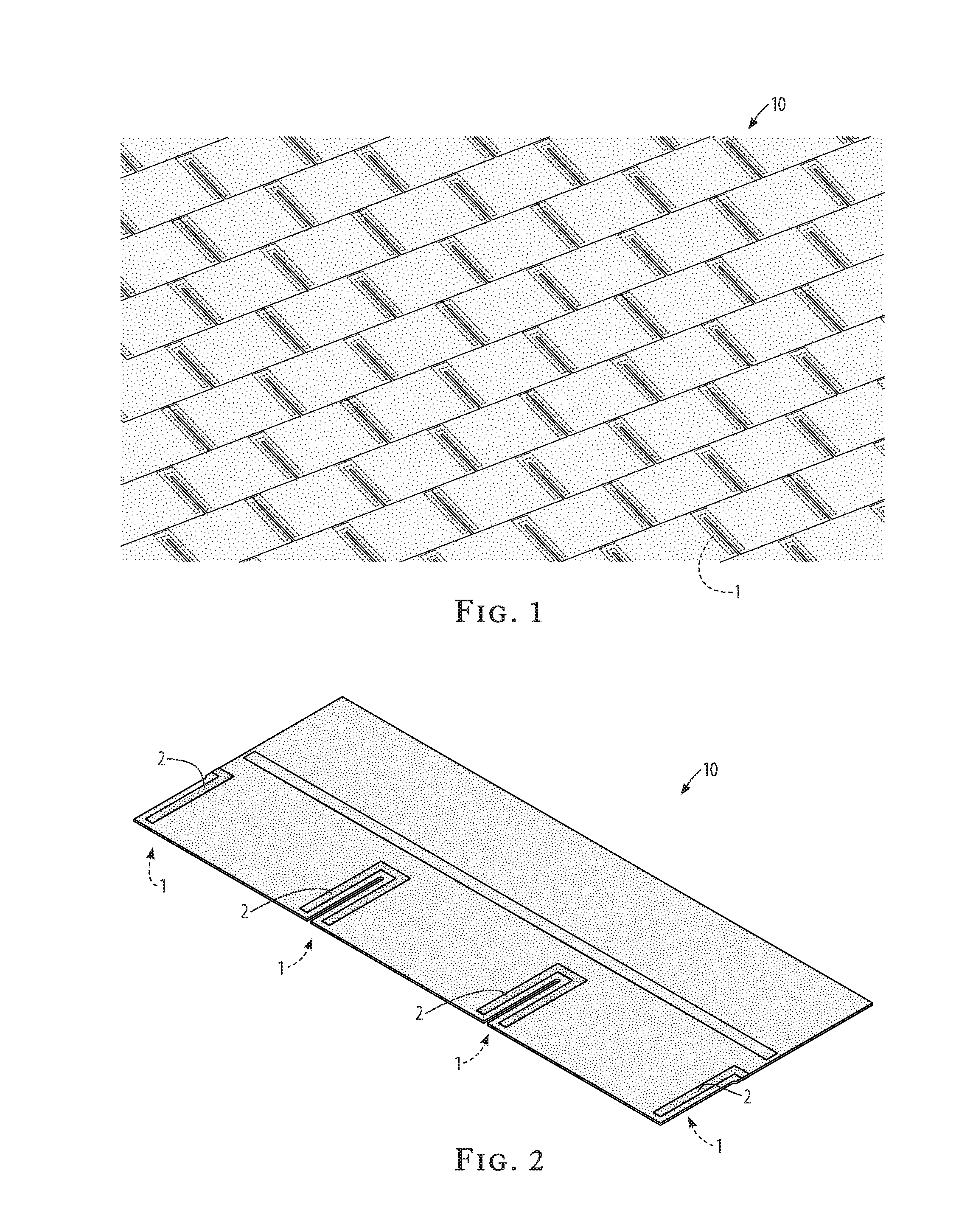
[0018] FIG. 1 is a schematic view of the sealed tabbed asphalt shingle system of the invention, in use;
[0019] FIG. 2 is a perspective view of the sealed tabbed asphalt shingle of the invention;
[0020] FIG. 3 is a top view of the sealed tabbed asphalt shingle of the invention;
[0021] FIG. 4 is a side view of the sealed tabbed asphalt shingle of the invention;
[0022] FIG. 5 is a bottom view of the sealed tabbed asphalt shingle of the invention;
[0023] FIG. 6 is a schematic view of improved tabbed asphalt shingles stacked one upon another for storage and transport;
[0024] FIG. 7 is a schematic view of the sealed tabbed asphalt shingles as installed, with an offset overlap;
[0025] FIG. 8 is a schematic view of removal of shielding tape from installed improved tabbed asphalt shingles;
[0026] FIG. 9 is a schematic view of an embodiment of the improved tabbed asphalt shingle of the invention utilizing adhesive applied at the time of installation; and
[0027] FIG. 10 is a schematic view of an embodiment of the improved tabbed asphalt shingle of the invention utilizing an activating substance applied to a pre-placed adhesive strip at the time of installation.
DETAILED DESCRIPTION OF THE INVENTION
[0028] Referring to FIG. 1, the sealed tabbed asphalt shingle system 10 of the invention is shown schematically in use on a building's roof. A sealant 1 is placed underneath and around the slots between tabs of the shingle. This sealant 1 prevents intrusion of water and wind through the slots and underneath the tabs of the shingle. In relation to the shingle as installed, the shingle is already sealed along the bottoms of the tabs, so there is no need to seal the bottom or open end of the slot. The sealant 1 is placed to seal the closed end of the slot and the two parallel legs of the slot, which, in existing tabbed-shingle methods, is not sealed, and would allow the intrusion of wind-driven water and of pooled water behind an obstruction such as a chimney, debris, or an ice dam on the roof.
[0029] Additionally, the sealant 1, placed above the closed end of the slot, is placed at the specified or recommended place for nailing the shingle to the underlayment. Therefore, the nail head will be directly covered by and protected by the sealant 1 against rust or corrosion from water and water vapor.
[0030] Referring to FIG. 2, FIG. 3, FIG. 4, & FIG. 5, different views of an exemplary shingle are provided, of an embodiment having pre-applied sealant 1 applied by the manufacturer. The sealant 1 is placed around each slot, on the bottom face of the shingle as installed. Optionally, in this embodiment, shielding tape 2 can be pre-applied to the corresponding top face of the shingle in order to prevent unwanted sealing when stacked for storage or transport. The sealant 1 should be capable of binding not only to the granular coated surface of the shingle, but also through that granular surface to the underlying main asphalt structure of the shingle.
[0031] Referring to FIG. 6, when the optional storage shield 2 is used in conjunction with pre-applied sealant 1, when shingles are stacked one upon another for storage or transportation, the sealant 1 on the bottom of an upper shingle rests upon the shielding tape 2 of the shingle beneath, and therefore the two shingles do not adhere to each other during storage and transportation.
[0032] Referring to FIG. 7, when the sealed tabbed asphalt shingles 10 are installed at the standard offset for such shingles, the sealant 1 areas are placed in contact with, and become sealed to, the upper, unexposed area of the shingle.
[0033] Referring to FIG. 8, after installation of an embodiment of the sealed tabbed asphalt shingle system 10, having optional shielding tape 2, the pieces of shielding tape 2 can be removed by brushing or sweeping, and discarded, or can be left to fall off in the first rainstorm, with the resulting liter picked up from the ground or cleaned out of the gutters. Optionally, the shielding tape 2 can be made of a material which is stable during storage and transportation of the shingles, but is easily degradable to eco-safe material after installation and exposure to the elements, which can be safely allowed to degrade and be blown and washed off of the roof.
[0034] Referring to FIG. 9, in an install-time embodiment 20 of the sealed tabbed asphalt shingle system and method, the sealant 1 can be applied to the proper areas on the underside of a standard tabbed shingle from an install-time sealant applicator 3.
[0035] Referring to FIG. 10, in a two-part sealant embodiment 30, the basic sealant 1 is activated or otherwise enhanced by an activator 4 from an activator applicator 5 at installation time. This two-part sealant can be an epoxy, or can be a sealant-and-solvent or sealant-and-activator combination. This two-part embodiment can provide a stronger bond overall, and can provide for installation under conditions such as extreme cold, where the heat of sunshine cannot be relied upon to set the seal, or where heating with a device such as a blowtorch cannot be utilized.
[0036] Many other changes and modifications can be made in the system and method of the present invention without departing from the spirit thereof. I therefore pray that my rights to the present invention be limited only by the scope of the appended claims.
* * * * *
D00000
D00001
D00002
D00003
D00004
D00005
D00006
XML
uspto.report is an independent third-party trademark research tool that is not affiliated, endorsed, or sponsored by the United States Patent and Trademark Office (USPTO) or any other governmental organization. The information provided by uspto.report is based on publicly available data at the time of writing and is intended for informational purposes only.
While we strive to provide accurate and up-to-date information, we do not guarantee the accuracy, completeness, reliability, or suitability of the information displayed on this site. The use of this site is at your own risk. Any reliance you place on such information is therefore strictly at your own risk.
All official trademark data, including owner information, should be verified by visiting the official USPTO website at www.uspto.gov. This site is not intended to replace professional legal advice and should not be used as a substitute for consulting with a legal professional who is knowledgeable about trademark law.