Method For Installing Rotary Machine, And Rotary Machine
Miyoshi; Tatsuya
U.S. patent application number 16/321273 was filed with the patent office on 2019-05-30 for method for installing rotary machine, and rotary machine. This patent application is currently assigned to MITSUBISHI HEAVY INDUSTRIES COMPRESSOR CORPORATION. The applicant listed for this patent is MITSUBISHI HEAVY INDUSTRIES COMPRESSOR CORPORATION. Invention is credited to Tatsuya Miyoshi.
| Application Number | 20190161934 16/321273 |
| Document ID | / |
| Family ID | 62490906 |
| Filed Date | 2019-05-30 |


| United States Patent Application | 20190161934 |
| Kind Code | A1 |
| Miyoshi; Tatsuya | May 30, 2019 |
METHOD FOR INSTALLING ROTARY MACHINE, AND ROTARY MACHINE
Abstract
A method for installing a compressor includes a preparing step of preparing a base plate that supports a support leg onto a foundation, a level adjusting member disposing step of disposing a plurality of level adjusting members having a wedge shape onto the base plate along an outline of a lower end portion of the support leg, an adjusting step of adjusting a horizontal level of a rotary machine main body by adjusting pushing amounts of the level adjusting members to the lower end portion of the support leg, and a fixing step of fixing positions of the support leg and the level adjusting members with respect to the base plate by welding the support leg to the plurality of level adjusting members.
| Inventors: | Miyoshi; Tatsuya; (Hiroshima-shi, JP) | ||||||||||
| Applicant: |
|
||||||||||
|---|---|---|---|---|---|---|---|---|---|---|---|
| Assignee: | MITSUBISHI HEAVY INDUSTRIES
COMPRESSOR CORPORATION Tokyo JP |
||||||||||
| Family ID: | 62490906 | ||||||||||
| Appl. No.: | 16/321273 | ||||||||||
| Filed: | December 7, 2016 | ||||||||||
| PCT Filed: | December 7, 2016 | ||||||||||
| PCT NO: | PCT/JP2016/086413 | ||||||||||
| 371 Date: | January 28, 2019 |
| Current U.S. Class: | 1/1 |
| Current CPC Class: | E02D 27/44 20130101; F04C 2230/60 20130101; F04B 39/121 20130101; F04B 39/14 20130101; F04B 35/04 20130101 |
| International Class: | E02D 27/44 20060101 E02D027/44; F04B 39/14 20060101 F04B039/14; F04B 39/12 20060101 F04B039/12 |
Claims
1. A method for installing a rotary machine that includes a plurality of support legs extending in a vertical direction and a rotary machine main body fixed to upper end portions of the support legs, the method comprising: a preparing step of preparing a base plate that supports the support legs onto a foundation; a level adjusting member disposing step of disposing a plurality of level adjusting members having a wedge shape onto the base plate along an outline of each of lower end portions of the support legs; a placing step of placing each of the support legs onto the plurality of level adjusting members; an adjusting step of adjusting a horizontal level of the rotary machine main body by adjusting pushing amounts of the level adjusting members to each of the lower end portions of the support legs; and a fixing step of fixing positions of each of the support legs and the level adjusting members with respect to the base plate by welding each of the support legs to the plurality of level adjusting members.
2. The method for installing a rotary machine according to claim 1, further comprising: a liner member disposing step of disposing a flat plate-shaped liner member onto the base plate before the level adjusting member disposing step, wherein in the level adjusting member disposing step, the plurality of level adjusting members are disposed onto the liner member fixed to the base plate, and in the fixing step, each of the support legs and the plurality of level adjusting members are welded to the liner member.
3. The method for installing a rotary machine according to claim 1, wherein in the preparing step, the existing support legs fixed on the base plate are removed from the base plate.
4. A rotary machine, comprising: a base plate installed on a foundation; a plurality of wedge-shaped level adjusting members provided on the base plate; a plurality of support legs which are placed on the plurality of level adjusting members and extend toward a vertical direction; a fixing unit which is formed by each of lower end portions of the support legs and the plurality of level adjusting members being welded to each other and fixes positions of each of the support legs and the level adjusting members with respect to the base plate; and a rotary machine main body supported by the plurality of support legs.
5. The method for installing a rotary machine according to claim 2, wherein in the preparing step, the existing support legs fixed on the base plate are removed from the base plate.
Description
TECHNICAL FIELD
[0001] The invention relates to a method for installing a rotary machine and a rotary machine.
BACKGROUND ART
[0002] For example, in a rotary machine disclosed in Patent Document 1, a rotary machine main body having a rotary shaft is supported by support legs. When installing such a rotary machine, the plurality of support legs are fixed on a base plate installed on a foundation. After then, the rotary machine is installed by installing the rotary machine main body onto the fixed support legs.
[0003] However, it is necessary to horizontally dispose the rotary shaft of the rotary machine main body in order to install such a rotary machine. For example, there is a method of adjusting the levelness of the rotary machine main body by adjusting the position or the height of the rotary machine main body with respect to upper end portions of the support legs in order to horizontally dispose the rotary shaft.
CITATION LIST
Patent literature
[0004] [Patent Document 1] Japanese Unexamined Patent Application, First Publication No. 2016-75194
SUMMARY OF INVENTION
Technical Problem
[0005] However, in a case where the support legs are already fixed to the rotary machine main body, it is impossible to adopt the method described above. For this reason, it is necessary to ensure the levelness of the rotary machine by adjusting the positions of the support legs with respect to the base plate.
[0006] An object of the present invention is to provide a method for installing a rotary machine and a rotary machine, in which the levelness of the rotary machine can be ensured by adjusting the positions of support legs with respect to a base plate.
Solution to Problem
[0007] According to a first aspect of the present invention, there is provided a method for installing a rotary machine that includes a plurality of support legs extending in a vertical direction and a rotary machine main body fixed to upper end portions of the support legs. The method for installing a rotary machine includes a preparing step of preparing a base plate that supports the support legs onto a foundation, a level adjusting member disposing step of disposing a plurality of level adjusting members having a wedge shape onto the base plate along an outline of each of lower end portions of the support legs, a placing step of placing each of the support legs onto the plurality of level adjusting members, an adjusting step of adjusting a horizontal level of the rotary machine main body by adjusting pushing amounts of the level adjusting members to each of the lower end portions of the support legs, and a fixing step of fixing positions of each of the support legs and the level adjusting members with respect to the base plate by welding each of the support legs to the plurality of level adjusting members.
[0008] According to such a configuration, the horizontal level adjustment of the upper end portions of the support legs can be performed by adjusting the pushing amounts of the wedge-shaped level adjusting members to the lower end portions of the support legs. Therefore, the level adjustment of the rotary machine main body fixed to the support legs with respect to the base plate can be easily and reliably performed.
[0009] According to a second aspect of the present invention, in the method for installing a rotary machine of the first aspect, a liner member disposing step of disposing a flat plate-shaped liner member onto the base plate before the level adjusting member disposing step may be further included. In the level adjusting member disposing step, the plurality of level adjusting members may be disposed onto the liner member fixed to the base plate, and in the fixing step, each of the support legs and the plurality of level adjusting members may be welded to the liner member.
[0010] According to such a configuration, even in a case where an upper surface of the base plate is not smooth, the level adjusting members can be disposed on a smooth surface of the flat plate-shaped liner member. Therefore, the level adjusting members can be easily moved when adjusting the pushing amounts of the level adjusting members to lower sides of the support legs.
[0011] According to a third aspect of the present invention, in the method for installing a rotary machine of the first or second aspect, in the preparing step, the existing support legs fixed on the base plate may be removed from the base plate.
[0012] According to such a configuration, a new rotary machine main body and new support legs can be installed with the use of the base plate to which the existing support legs had been fixed after removing the existing support legs. Therefore, work efficiency improvement and cost reduction can be achieved without a need for reinstalling the base plate.
[0013] According to a fourth aspect of the present invention, there is provided a rotary machine including a base plate installed on a foundation, a plurality of wedge-shaped level adjusting members provided on the base plate, a plurality of support legs which are placed on the plurality of level adjusting members and extend toward a vertical direction, a fixing unit which is formed by each of lower end portions of the support legs and the plurality of level adjusting members being welded to each other and fixes positions of each of the support legs and the level adjusting members with respect to the base plate, and a rotary machine main body supported by the plurality of support legs.
Advantageous Effects of Invention
[0014] According to the present invention, the levelness of the rotary machine main body with respect to the base plate can be easily and reliably adjusted when installing the rotary machine.
BRIEF DESCRIPTION OF DRAWINGS
[0015] FIG. 1 is an elevation showing a schematic configuration of a first compressor before being replaced, to which a method for installing a rotary machine of the embodiment is applied.
[0016] FIG. 2 is a flow chart showing flow of the method for installing a rotary machine of the embodiment.
[0017] FIG. 3 is a perspective view showing a state where a first compressor main body is removed from a first support leg in the method for installing a rotary machine of the embodiment.
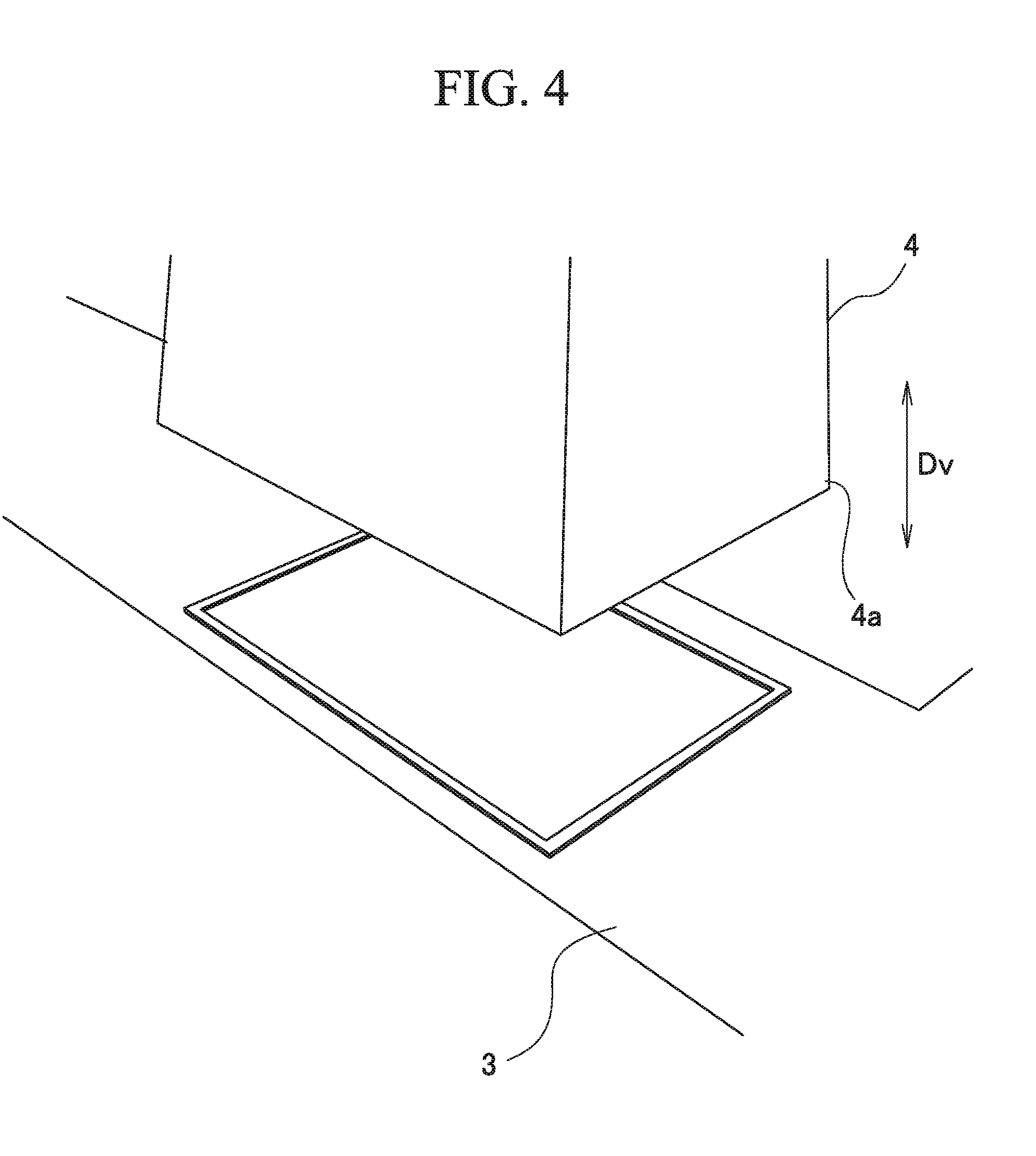
[0018] FIG. 4 is a perspective view showing a state where the first support leg is removed from a base plate in the method for installing a rotary machine of the embodiment.
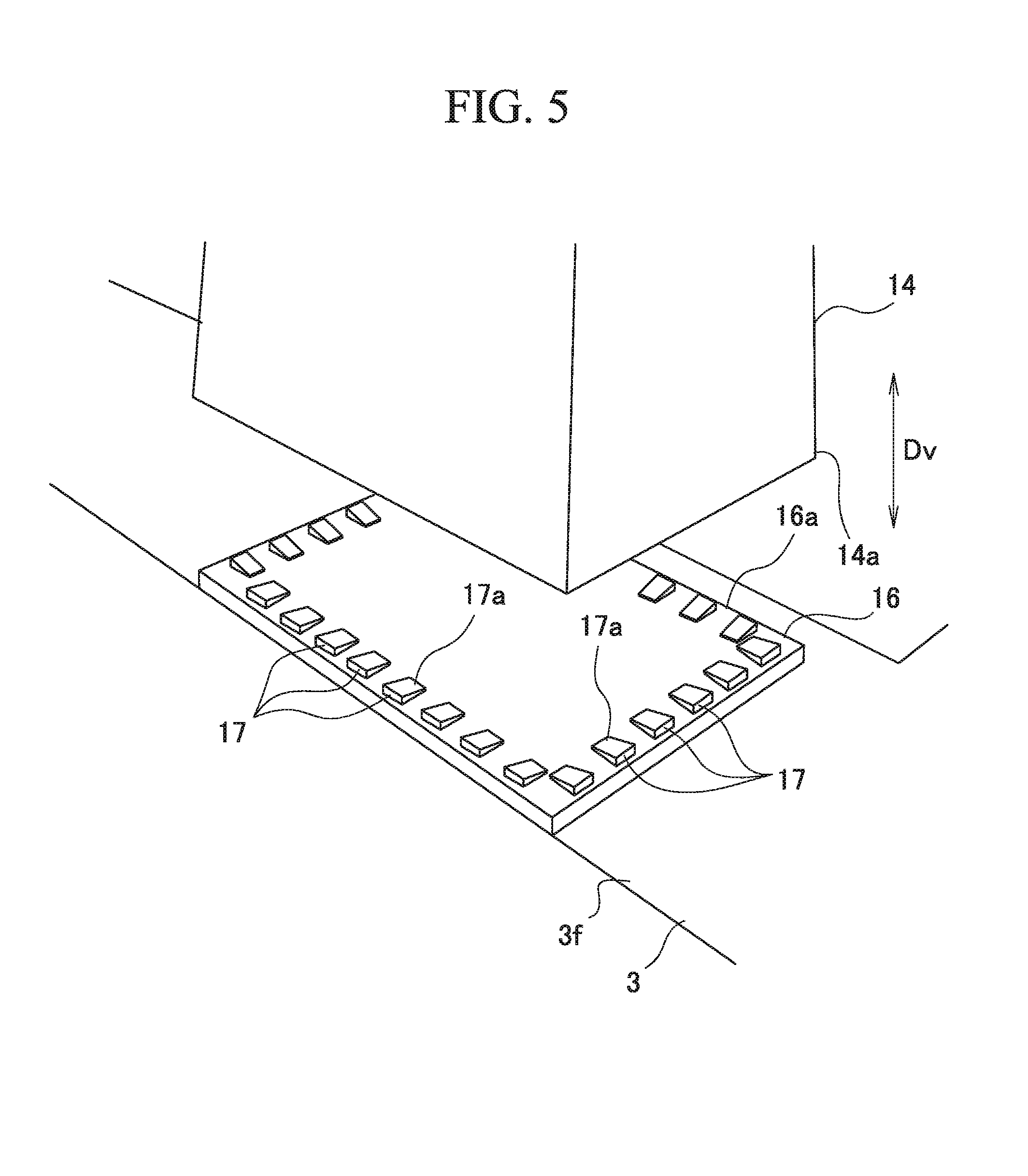
[0019] FIG. 5 is a perspective view showing a state where a level adjusting member is set on a liner plate in the method for installing a rotary machine of the embodiment.
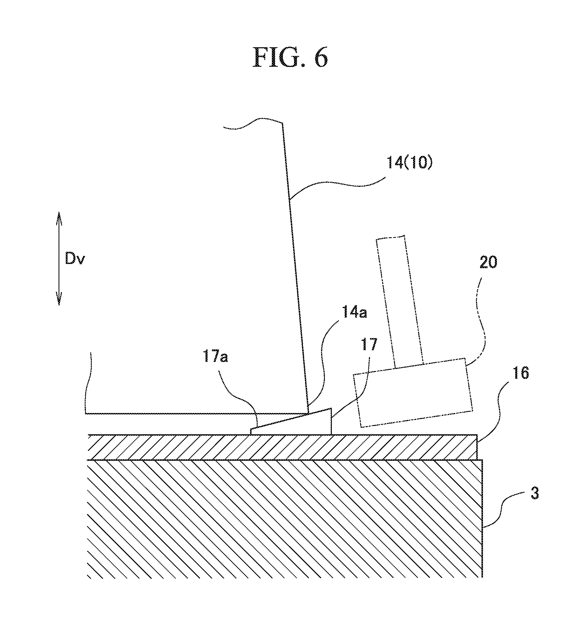
[0020] FIG. 6 is a perspective view showing a state where horizontal level adjustment of a second compressor main body is performed by pushing the level adjusting member so as to be placed under a second support leg in the method for installing a rotary machine of the embodiment.
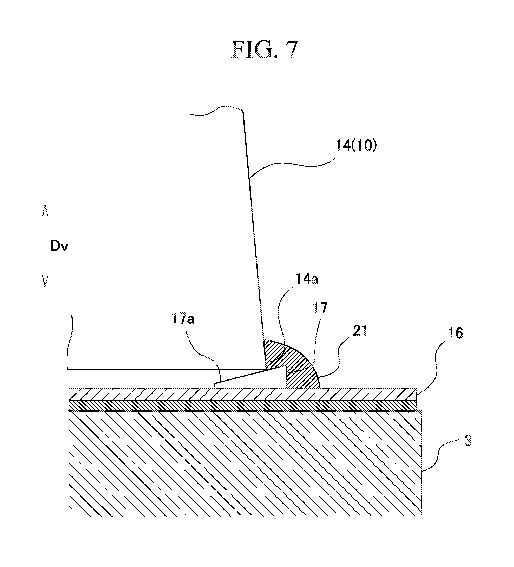
[0021] FIG. 7 is a perspective view showing a state where the second support leg is welded to the level adjusting member and the liner plate in the method for installing a rotary machine of the embodiment.
[0022] FIG. 8 is an elevation showing the second compressor installed in accordance with the method for installing a rotary machine of the embodiment.
DESCRIPTION OF EMBODIMENTS
[0023] Hereinafter, a method for installing a rotary machine and a rotary machine of the present invention will be described with reference to the drawings. In this embodiment, a case where an already installed compressor (rotary machine) is replaced with a new compressor (rotary machine) and the new compressor is installed will be described as an example of the method for installing a rotary machine.
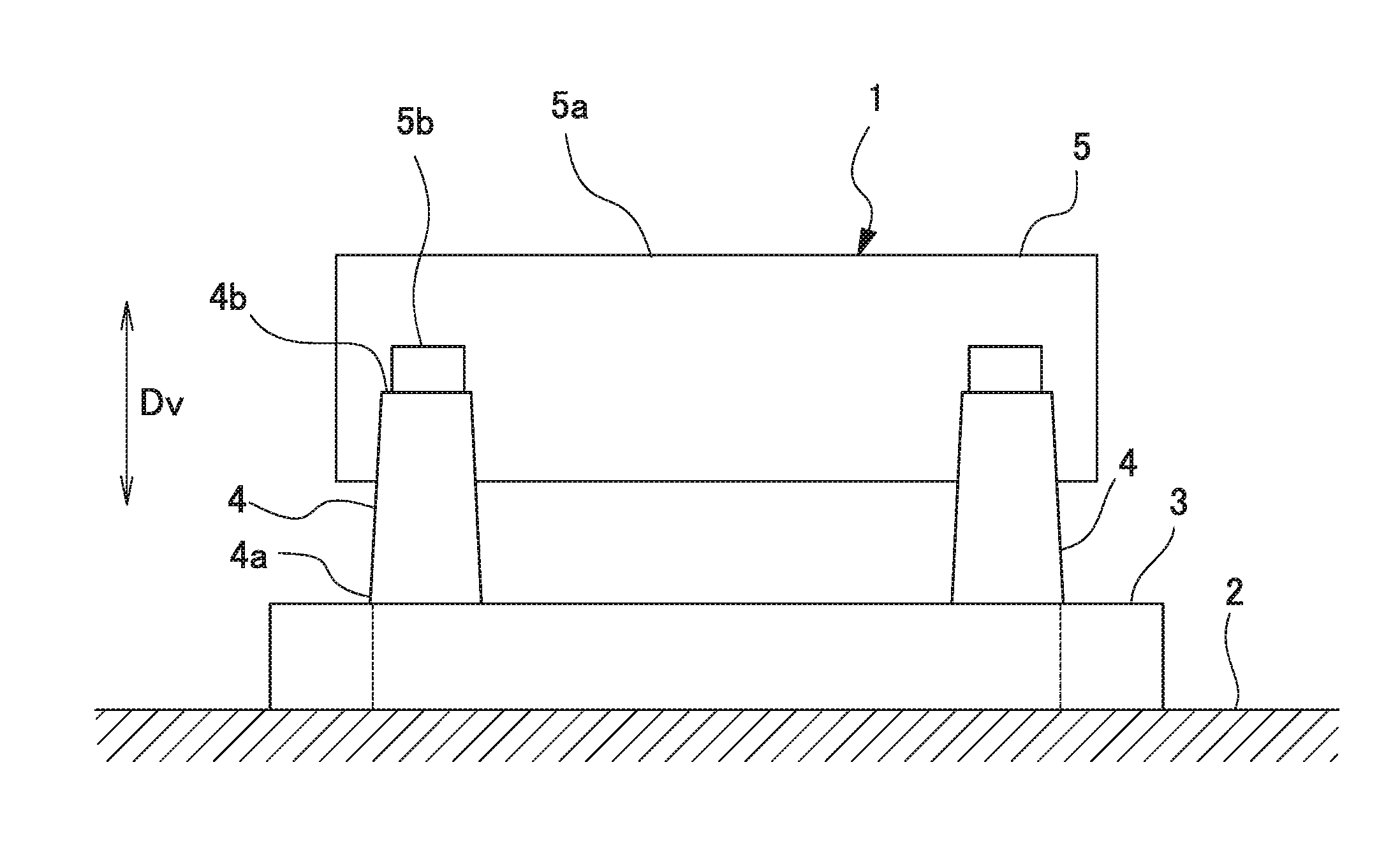
[0024] As shown in FIG. 1, a first compressor 1, which is the already installed compressor, includes a base plate 3, a plurality of (for example, four in the embodiment) first support legs (support legs) 4, and a first compressor main body (compressor main body) 5.
[0025] The base plate 3 is provided on a foundation 2 built on the ground. The base plate 3 can support the first support legs 4. The base plate 3 forms a rectangular frame in plan view, for example, by a plurality of steel materials being combined.
[0026] The first support legs 4 are bonded and fixed onto the base plate 3. The first support legs 4 extend toward a vertical direction Dv. Lower end portions 4a of the first support legs 4 are directly welded onto the base plate 3. The first support legs 4 extend to an upper side in the vertical direction Dv from the lower end portions 4a toward upper end portions 4b.
[0027] The first compressor main body 5 has a casing 5a forming a shell thereof and supported portions 5b protruding outwards from an outer peripheral surface of the casing 5a. The first compressor main body 5 is integrally formed with the plurality of first support legs 4 by the supported portions 5b being bonded in a state of being placed on the upper end portions 4b of the first support legs 4 respectively.
[0028] In order to replace the first compressor 1 described above with a second compressor 10, which is the new compressor, work is performed step by step in accordance with flow shown in FIG. 2. First, as shown in FIG. 3, the first compressor main body 5 is removed from the plurality of first support legs 4 (compressor main body removing step S1). Specifically, portions between the upper end portions 4b of the first support legs 4 and the supported portions 5b are cut by fusion cutting or the like, and thus the first support legs 4 and the first compressor main body 5 are separated from each other. After then, the first compressor main body 5 is removed from the first support legs 4.
[0029] Next, as shown in FIG. 4, the base plate 3 is prepared on the foundation by removing each of the first support legs 4 fixed on the base plate 3 from the base plate 3 (preparing step S2). Specifically, a portion between each of the lower end portions 4a of the first support legs 4 and the base plate 3 is cut, for example, by fusion cutting or the like. After then, the plurality of first support legs 4 are removed from the base plate 3. After the first support legs 4 are removed from the base plate 3, portions of the base plate 3 which had been bonded to the first support legs 4 are polished to eliminate unevenness. Accordingly, the preparation of the base plate 3 supporting the support legs is completed. After then, second support legs 14 and a second compressor main body (rotary machine main body) 15 of the second compressor 10 which is the new compressor (refer to FIG. 8) are installed onto the base plate 3.
[0030] As shown in FIG. 8, the second support legs 14 extend toward the vertical direction Dv as the first support legs 4 do. The second support legs 14 extend to the upper side in the vertical direction Dv from lower end portions 14a toward upper end portions 14b.
[0031] The second compressor main body 15 has a casing 15a forming a shell thereof and supported portions 15b protruding outwards from an outer peripheral surface of the casing 15a, like the first compressor main body 5.
[0032] As shown in FIG. 5, after removing the first support legs 4 and before a level adjusting member disposing step S4 to be described later, new liner plates (liner members) 16 are installed onto portions on the base plate 3 where the second support legs 14, which are new support legs, are to be installed (liner member disposing step S3). The liner plates 16 have a rectangular plate shape. The liner plates 16 are formed of a steel material that is the same as the base plate 3. The liner plates 16 are disposed at an installing position of the second compressor 10, which is the new compressor to be described later. The liner plates 16 are integrally fixed to the base plate 3 by outer peripheral portions 16a of the liner plates 16 being welded to an upper surface 3f of the base plate 3. The liner plates 16 may be disposed so as to overlap portions of the base plate 3, to which the first support legs 4 had been bonded.
[0033] Next, a plurality of level adjusting members 17 are disposed onto the base plate 3 along each of outlines of the lower end portions 14a of the second support legs 14 (level adjusting member disposing step S4). In the embodiment, the plurality of level adjusting members 17 are disposed onto each of the liner plates 16 fixed to the base plate 3. Each of the level adjusting members 17 has a wedge shape of which a height dimension gradually decreases toward a tip portion 17a. The level adjusting members 17 are formed of a steel material that is the same as the base plate 3. It is preferable to dispose the plurality of level adjusting members 17 at equal intervals in a peripheral direction along each of the outlines of the lower end portions 14a of the second support legs 14. In addition, each of the level adjusting members 17 is disposed such that the tip portion 17a faces an inner side of the second support leg 14 when seen from the upper side in the vertical direction Dv.
[0034] After then, the second support legs 14 and the second compressor main body (rotary machine main body) 15 of the second compressor 10 which is the new compressor (refer to FIG. 8) are placed (placing step S5). Specifically, each of the second support legs 14 is placed onto the plurality of level adjusting members 17. At this time, the tip portions 17a of the level adjusting members 17 come into a state of being sandwiched between the second support leg 14 and the liner plate 16, and part of each of the level adjusting members 17 comes into a state of projecting from the second support leg 14 to an outer side.
[0035] The second support legs 14 may be integrally attached to the second compressor main body 15 in advance, or the second support legs 14 may be attached to the second compressor main body 15 after fixing the second support legs 14 to the base plate 3. In a case where the second support legs 14 and the second compressor main body 15 are integrally attached to each other in advance, the second compressor main body 15 to which the plurality of second support legs 14 are attached is lifted, and each of the second support legs 14 is put onto the plurality of level adjusting members 17 set on each of the liner plates 16. Accordingly, the plurality of level adjusting members 17 are interposed between each of the liner plates 16 and each of the second support legs 14.
[0036] Next, as shown in FIG. 6, the horizontal level of the second compressor main body 15 is adjusted by adjusting the pushing amounts of the level adjusting members 17 to the lower end portions 14a of the second support legs 14 (adjusting step S6). Specifically, as for each of the second support legs 14, the level adjusting members 17 are hit into an interior between the liner plate 16 and the second support leg 14 by a hammer 20 or the like. Accordingly, the pushing amounts of the level adjusting members 17 with respect to the lower end portion 14a of the second support leg 14 are adjusted. Since the level adjusting members 17 have a wedge shape, the height of the upper end portion 14b of the second support leg 14 is adjusted by the adjustment of the pushing amounts. As a result, the height of the supported portion 15b of the second compressor main body 15 placed onto the upper end portion 14b of the second support leg 14 is adjusted. Accordingly, the horizontal level adjustment of the second compressor main body 15 is performed such that a rotary shaft (not shown) provided in the second compressor main body 15 becomes horizontal.
[0037] As shown in FIG. 7, after the adjusting step S6, each of the lower end portions 14a of the second support legs 14, the liner plate 16, and the level adjusting members 17 are welded to each other. Accordingly, the positions of the second support leg 14 and the level adjusting members 17 are fixed with respect to the base plate 3 (fixing step S7). The lower end portion 14a of the second support leg 14 and the liner plate 16 are continuously welded to each other over the entire periphery of the lower end portion 14a of the second support leg 14 so as to engulf the level adjusting members 17. Accordingly, a weld bead (fixing unit) 21 is formed so as to cover the lower end portion 14a of the second support leg 14 from the peripheral direction. The plurality of level adjusting members 17 interposed between each of the liner plates 16 and each of the second support legs 14 are bonded to the liner plate 16 by the weld bead 21 so as to be integrally attached to the second support leg 14.
[0038] The weld bead 21 is formed by the lower end portion 14a of the second support leg 14 being welded to the plurality of level adjusting members 17. The weld bead 21 fixes the positions of the second support leg 14 and the level adjusting members 17 with respect to the base plate 3 via the liner plate 16.
[0039] Accordingly, as shown in FIG. 8, the already installed first compressor 1 can be replaced with the new second compressor 10 and the second compressor 10 can be installed. Therefore, the second compressor 10 includes the base plate 3, the liner plates 16, the level adjusting members 17, the second support legs 14, the weld beads 21, and the second compressor main body 15.
[0040] In the method for installing a rotary machine and the rotary machine of the embodiment described above, the horizontal level adjustment of the upper end portions 14b of the second support legs 14 with respect to the base plate 3 can be performed by adjusting the pushing amounts of the wedge-shaped level adjusting members 17 to each of the lower end portions 14a of the second support legs 14. Therefore, the horizontal level adjustment of the second compressor main body 15, which is fixed to the upper end portions 14b of the second support legs 14 via the supported portions 15b, can be performed. Accordingly, the levelness of the second compressor main body 15 with respect to the base plate 3 can be easily and reliably adjusted. Therefore, the levelness of the second compressor 10 can be ensured by adjusting the positions of the second support legs 14 with respect to the base plate 3.
[0041] In addition, the flat plate-shaped liner plates 16 are provided on the base plate 3, and the plurality of level adjusting members 17 are disposed on each of the liner plates 16. For this reason, even in a case where the upper surface of the base plate 3 is not smooth, the level adjusting members 17 can be disposed on each of smooth surfaces of the flat plate-shaped liner plates 16. Therefore, regardless of the state of the base plate 3, the level adjusting members 17 can be easily moved when adjusting the pushing amounts of the level adjusting members 17 to lower sides of the second support legs 14.
[0042] In addition, after the existing first compressor main body 5 and the existing first support legs 4 are removed, the new second compressor main body 15 and the new second support legs 14 are installed with the use of the base plate 3 to which the existing first support legs 4 had been fixed. Therefore, work efficiency improvement and cost reduction can be achieved without a need for reinstalling the base plate 3 when newly installing a compressor.
[0043] Although the embodiment of the present invention has been described in detail with reference to the drawings hereinbefore, respective configurations, combinations of the configurations of the embodiment, and the like are merely examples. It is possible to make addition, omission, replacement, and other modifications of a configuration without departing from the scope of the present invention. In addition, the present invention is not limited by the embodiment, and is limited only by claims.
[0044] For example, although a case where the already installed first compressor 1 is replaced with the new second compressor 10 is given as an example in the embodiment, the invention is not limited thereto. For example, even in a case where the new second compressor 10 is installed at a place where there is no first compressor 1, it is possible to apply the present invention. In this case, it is sufficient to newly install the base plate 3 onto the foundation in the step of preparing the base plate 3.
[0045] In addition, although the compressor is given as an example of a rotary machine in the embodiment, without being limited thereto, the method for installing a rotary machine of the present invention is applicable even when various turbines, electric motors, or the like are applied as a rotary machine.
INDUSTRIAL APPLICABILITY
[0046] In the method for installing a rotary machine and the rotary machine, the levelness of the rotary machine can be ensured by adjusting the positions of the support legs with respect to the base plate.
REFERENCE SIGNS LIST
[0047] 1: first compressor (rotary machine)
[0048] 2: foundation
[0049] 3: base plate
[0050] 3f: upper surface
[0051] 4: first support leg (support leg)
[0052] 4a: lower end portion
[0053] 4b: upper end portion
[0054] 5: first compressor main body (rotary machine main body)
[0055] 5a: casing
[0056] 5b: supported portion
[0057] 10: second compressor (rotary machine)
[0058] 14: second support leg (support leg)
[0059] 14a: lower end portion
[0060] 14b: upper end portion
[0061] 15: second compressor main body (rotary machine main body)
[0062] 16: liner plate (liner member)
[0063] 16a: outer peripheral portion
[0064] 17: level adjusting member
[0065] 17a: tip portion
[0066] 20: hammer
[0067] 21: weld bead (fixing unit)
[0068] S1: compressor main body removing step
[0069] S2: preparing step
[0070] S3: liner member disposing step
[0071] S4: level adjusting member disposing step
[0072] S5: placing step
[0073] S6: adjusting step
[0074] S7: fixing step
* * * * *
D00000
D00001
D00002
D00003
D00004
D00005
D00006
D00007
D00008
XML
uspto.report is an independent third-party trademark research tool that is not affiliated, endorsed, or sponsored by the United States Patent and Trademark Office (USPTO) or any other governmental organization. The information provided by uspto.report is based on publicly available data at the time of writing and is intended for informational purposes only.
While we strive to provide accurate and up-to-date information, we do not guarantee the accuracy, completeness, reliability, or suitability of the information displayed on this site. The use of this site is at your own risk. Any reliance you place on such information is therefore strictly at your own risk.
All official trademark data, including owner information, should be verified by visiting the official USPTO website at www.uspto.gov. This site is not intended to replace professional legal advice and should not be used as a substitute for consulting with a legal professional who is knowledgeable about trademark law.