Packing Material Including Cushion
HASHIMOTO; Takeshi ; et al.
U.S. patent application number 16/185532 was filed with the patent office on 2019-05-30 for packing material including cushion. This patent application is currently assigned to KONICA MINOLTA INC.. The applicant listed for this patent is KONICA MINOLTA INC.. Invention is credited to Takeshi HASHIMOTO, Hiromi MIZUGUCHI, Narutaka YOSHIDA.
| Application Number | 20190161264 16/185532 |
| Document ID | / |
| Family ID | 66634267 |
| Filed Date | 2019-05-30 |


| United States Patent Application | 20190161264 |
| Kind Code | A1 |
| HASHIMOTO; Takeshi ; et al. | May 30, 2019 |
PACKING MATERIAL INCLUDING CUSHION
Abstract
An air cushion having first and second rooms bends at a partition at a corner of a multi-function peripheral (MFP) and contacts a first face of the MFP at a first room outer surface and a second face of the MFP at an second room outer surface. An outer case applies pressure to the outer surfaces of the first and second rooms and presses the first and second rooms to the MFP. When the first room receives a force from outside the outer case, gas moves from the first room to the second room against pressure the outer case applies to the second room, such that a side wall of the outer case contacting the second room deforms. Upon removal of the force, the side wall returns to an original flat state and presses the second room, such that the gas returns from the second room to the first room.
| Inventors: | HASHIMOTO; Takeshi; (Okazaki-shi, JP) ; YOSHIDA; Narutaka; (Toyokawa-shi, JP) ; MIZUGUCHI; Hiromi; (Toyokawa-shi, JP) | ||||||||||
| Applicant: |
|
||||||||||
|---|---|---|---|---|---|---|---|---|---|---|---|
| Assignee: | KONICA MINOLTA INC. Tokyo JP |
||||||||||
| Family ID: | 66634267 | ||||||||||
| Appl. No.: | 16/185532 | ||||||||||
| Filed: | November 9, 2018 |
| Current U.S. Class: | 1/1 |
| Current CPC Class: | B65D 85/68 20130101; B65D 81/052 20130101; B65D 77/061 20130101; B65D 2585/689 20130101; B65D 2585/6892 20130101; B65D 81/054 20130101 |
| International Class: | B65D 81/05 20060101 B65D081/05; B65D 85/68 20060101 B65D085/68; B65D 77/06 20060101 B65D077/06 |
Foreign Application Data
| Date | Code | Application Number |
|---|---|---|
| Nov 24, 2017 | JP | 2017-225759 |
Claims
1. A packing material comprising: an outer case allowing a to-be-packed object to be put inside; and a cushion arranged in a gap between the outer surface of the object and the inner wall of the outer case, including: a bag containing gas and hermetically sealed; a partition linearly dividing the inside of the bag into first and second rooms of the same capacity; and a duct connecting between the first and second rooms, wherein when the partition is placed along an edge of the object that is shared by first and second outer faces of the object, the cushion can bend at the partition and contact the first outer face of the object at the outer surface of the first room of the bag and the second outer face of the object at the outer surface of the second room of the bag, the outer case, when containing the object and the cushion, applies pressure to the outer surfaces of the first and second rooms of the bag through the inner wall contacting the outer surfaces of the first and second rooms, and the pressure includes a first component pressing the first room to the first outer face of the object and a second component pressing the second room to the second outer face of the object, and when the outer surface of the first room of the bag receives a force through the outer case from its outside, gas moves from the first room through the duct to the second room against the pressure applied by the outer case to the second room, and when the force from the outside of the outer case is removed, gas returns from the second room through the duct to the first room due to the pressure applied by the outer case to the second room.
2. The packing material according to claim 1, wherein the bag is made of a soft plastic sheet, and the partition is an area where two inner surfaces of the bag, which are placed across a space inside of the bag, are welded or adhered to each other.
3. The packing material according to claim 1, wherein the outer case has a higher stiffness than the cushion, and the pressure applied by the outer case to the first and second rooms of the bag is based on a stress of the outer case preventing its deformation caused by the gas pressure of the first and second rooms.
4. The packing material according to claim 1, wherein a filling ratio of the gas in the bag is higher than 50% but lower than 100%.
5. The packing material according to claim 4, wherein the filling ratio of the gas in the bag is 55-85%.
6. The packing material according to claim 1, wherein the ratio of the width of the duct to the length of the boundary between the first and second rooms of the bag is 5-30%.
7. The packing material according to claim 1, wherein at least one of the first and second rooms of the bag includes a thickness limiter, a collapsed area included in the two inner surfaces of the bag placed across the space inside of the bag, preventing the first or second room from swelling by the contained gas to limit the thickness of the first or second room.
8. The packing material according to claim 7, wherein the bag is made of a soft plastic sheet, and the thickness limiter is an area where the two inner surfaces of the bag placed across the space inside of the bag are welded or adhered to each other.
9. The packing material according to claim 7, wherein the thickness limiter is arranged in both the first and second rooms in a manner symmetric with respect to the partition.
10. The packing material according to claim 7, wherein, with respect to a line parallel to the partition and passing through the edge of the thickness limiter closest to the partition, a portion of the first or second room on the opposite side of the partition has a capacity ratio to the entirety of the first or second room, and the capacity ratio is equal to the filling ratio of the gas in the bag.
11. The packing material according to claim 1, further comprising a protect sheet placed between the bag of the cushion and the outer case or the object, wherein, the partition includes a coupler coupling the protect sheet with the bag.
12. The packing material according to claim 1, wherein the cushion further includes a bar, when the bag bends at the partition, connecting between the edges of the first and second rooms on the same side in the longitudinal direction of the partition to fix an angle of the bag.
Description
[0001] This application claims priority to Japanese Patent Application No. 2017-225759 filed Nov. 24, 2017, the contents of which are hereby incorporated herein by reference in its entirety.
BACKGROUND
Technical Field
[0002] The present disclosure relates to packing technology, and in particular to cushions.
Description of the Related Art
[0003] Cushions are indispensable for transportation of components or products vulnerable to external vibrations and shocks, such as high-precision molded components, precision machines, and electronic appliances. Cushions are each a member having high elasticity or plasticity and are placed around an object to be transported, i.e. a package. Specifically, when a package is stored in an outer case made of cardboard, wood, or the like, cushions surround the package or fill gaps between the package and the outer case to support the package inside the outer case. When the outer case receives a vibration or shock from the outside during transportation of the package, the cushions are deformed by the vibration or shock and absorb the vibration or shock. This enables the cushions to mitigate vibration and shock actually transmitted to the package and prevent it from being damaged by the vibration and shock.
[0004] There are various kinds of cushions, and cushions relatively often used are roughly classified into block and separate types. Block-type cushions are molded in advance to fit the shape of the package, and often have a role of supporting and fixing the package inside the outer case. Separate-type cushions are made of, for example, foamed plastic such as sponge or foam, paper, or wood. Separate-type cushions have a form of sheets or chips, and are wrapped around the package, crumpled, and packed into gaps between the outer case and the package, or filled into the entirety of the gaps when packing. Separate-type cushions are made of, for example, paper, cloth, foamed plastic, or bubble films (also referred to as bubble wraps, composite films between which many cells containing air are sandwiched.)
[0005] Increase in quantity of disposed packing materials is considered problematic, following the increase of interest toward environmental problems such as global warming. Since a significant amount of disposed packing materials are incinerated, there is a strong demand for reduction in an amount of both harmful gas generated and carbon dioxide emitted in the incineration. As a measure for responding to such demand, reduction of foamed plastic used as packing materials is considered. Use of foamed plastic, specifically as block-type cushions has problems such as difficulty in downsizing (being voluminous,) difficulty in recycling, and a significant amount of heat emission and generation of various kinds of harmful gases when burned. Accordingly, reduction of foamed plastic is effective for dealing with environmental problems.
[0006] Reduction of foamed plastic requires cushions substituted for them. One candidate for the substitution is air cushions, which typically consist of a series of bags made of, for example, soft plastic sheets (for example, see JP 1995-285581 and JP 1995-291358.) The bags are filled with gas such as air, and when receiving an external force, allows the gas to be compressed to absorb and mitigate the external force.
[0007] However, air cushions are disadvantageous in that their bags easily rupture when receiving an external shock, which requires a measure for further improving their buffering effects. One known example of such measures is a structure described in JP 2003-341739 and JP 2004-323048. In this structure, two or more bags are interconnected to allow gas to be movable therebetween. In this case, when one of the bags is compressed by an external force, gas moves from the one bag to the other. This reduces the risk of rupture of the one bag by the external force and improves its buffering effect because resistance such as friction that the moving gas receives converts energy of the external force into diffused heat or the like.
SUMMARY
[0008] The kinds of air cushions that allow gas to move between their bags by external forces have structures devised to cause the gas to receive greater resistance when passing through a communication path between the bags in order to achieve sufficiently high buffering effects. For example, the structure described in JP 2003-341739 has a source bag from which gas moves and a sink bag into which the gas moves with a smaller capacity than the source bag. The structure described in JP 2004-323048 has two communication paths between the bags, which each have unidirectionality by a check valve that allows gas to pass in opposing directions. However, such devices increase the number of components and complicate the structures, and therefore, are disadvantageous in production cost reduction. Further, gas that an external force moved from one bag to the other is returned into the original bag by gas pressure difference between the bags when the external force is removed from the bags. However, the gas pressure difference is often too low to surely return all the gas to the original bag. Accordingly, it is difficult to ensure that the bag having received the external force fully restores its buffering capability after the bag is released from the external force. If the bag has a smaller amount of gas due to the insufficient restoration, problems caused by lowering of the buffering effect may occur when the bag receives an external force again; for example, the package may be damaged by a collapse of the bag (a phenomenon in which the gas pressure of the bag fails to resist the external force, and consequently, the film on one side of the bag by receiving the external force falls down and collides with the film on the other side.)
[0009] The present disclosure aims at solving the above-described problems, and specifically, at providing packing material enabling cushions to exert sufficiently high resistance against gas moved between the bags by external forces, and to restore their buffering capacity by release from the external forces, without increase in number of their components or complicating their structures.
[0010] A packing material reflecting at least one aspect of the present disclosure includes an outer case allowing a to-be-packed object to be put inside; and a cushion arranged in a gap between the outer surface of the object and the inner wall of the outer case. The packing material includes: a bag containing gas and hermetically sealed; a partition linearly dividing the inside of the bag into first and second rooms of the same capacity; and a duct connecting between the first and second rooms. When the partition is placed along an edge of the object that is shared by first and second outer faces of the object, the cushion can bend at the partition and contact the first outer face of the object at the outer surface of the first room of the bag and the second outer face of the object at the outer surface of the second room of the bag. The outer case, when containing the object and the cushion, applies pressure to the outer surfaces of the first and second rooms of the bag through the inner wall contacting the outer surfaces of the first and second rooms, and the pressure includes a first component pressing the first room to the first outer face of the object and a second component pressing the second room to the second outer face of the object. When the outer surface of the first room of the bag receives a force through the outer case from its outside, gas moves from the first room through the duct to the second room against the pressure applied by the outer case to the second room. When the force from the outside of the outer case is removed, gas returns from the second room through the duct to the first room due to the pressure applied by the outer case to the second room.
BRIEF DESCRIPTION OF THE DRAWINGS
[0011] The advantages and features provided by one or more embodiments of the invention will become more fully understood from the detailed description given hereinbelow and the appended drawings which are given by way of illustration only, and thus are not intended as a definition of the limits of the invention. In the drawings:
[0012] FIG. 1A is a perspective diagram illustrating an external view of an MFP that is an image forming device to be packed, FIG. 1B is a perspective diagram illustrating an external view of components of a packing material used for the MFP in FIG. 1A that are placed around an upper portion of the MFP, and FIG. 1C is a perspective diagram illustrating an external view of components of the packing material used for the MFP in FIG. 1A that are placed around a lower portion of the MFP;
[0013] FIG. 2A is a perspective diagram illustrating an external view in a state in which the components of the packing material in FIGS. 1B and 1C are placed around the MFP, FIG. 2B is a perspective diagram illustrating an external view of an outer case that is a component of the packing material used for the MFP, and FIG. 2C is a perspective diagram illustrating an external view in a state in which the packing material and the MFP in FIG. 2A are covered by the outer case in FIG. 2B;
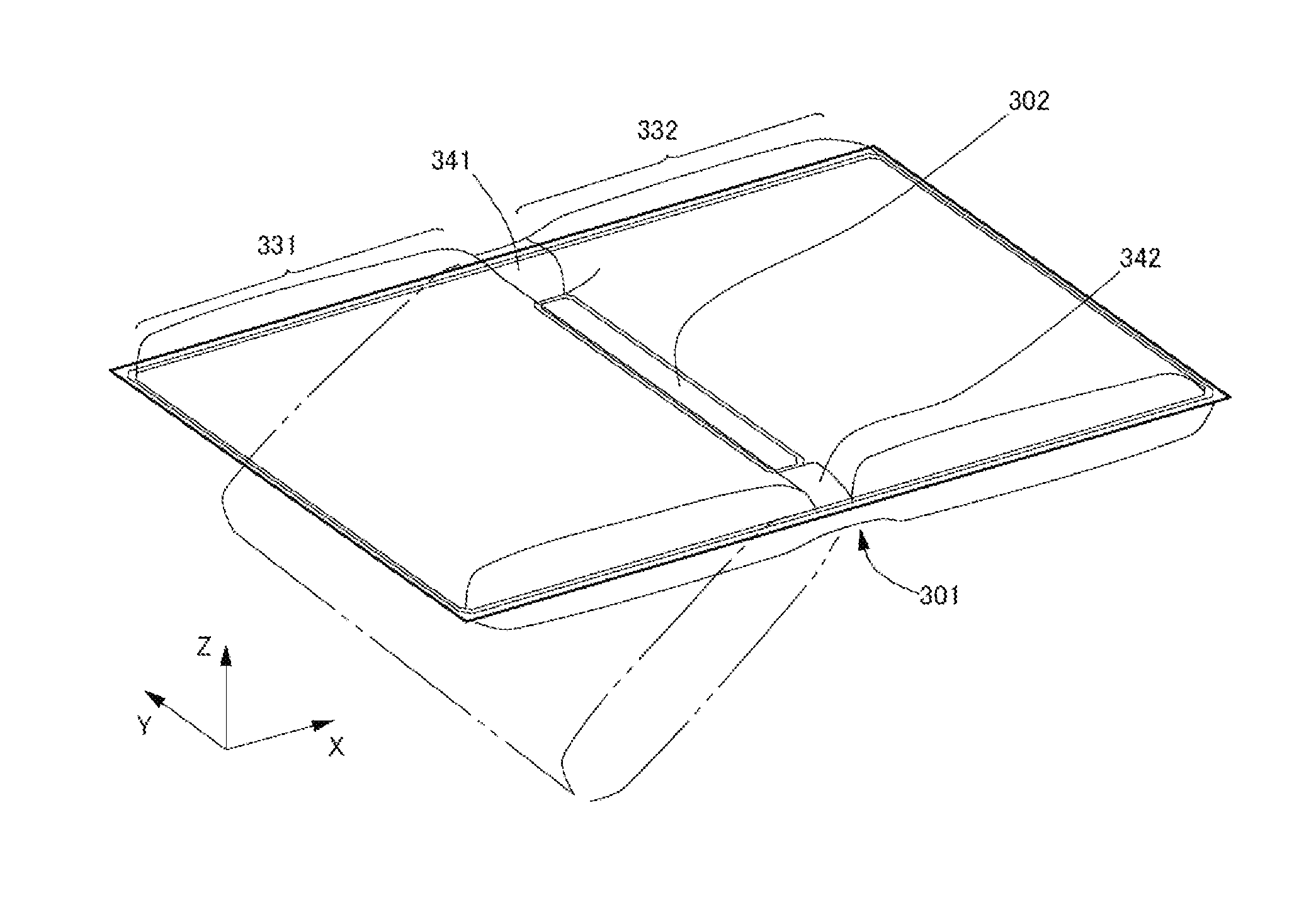
[0014] FIG. 3A is a diagram illustrating a plan view of a third air cushion, and FIG. 3B is a perspective diagram of the third air cushion;
[0015] FIG. 4A is a cross-sectional diagram of the outer case and the third air cushion, taken along line IV-IV in FIG. 2A, and FIG. 4B is a cross-sectional diagram of the outer case and the third air cushion in a state after a shock force in FIG. 2A has been removed;
[0016] FIG. 5 is a graph of buffering capability of the third air cushion in a state in FIG. 4A;
[0017] FIG. 6A is an elevation diagram that is common to a first air cushion and a second air cushion, and FIG. 6B is a perspective diagram illustrating an external view after the first air cushion (the second air cushion) has been assembled;
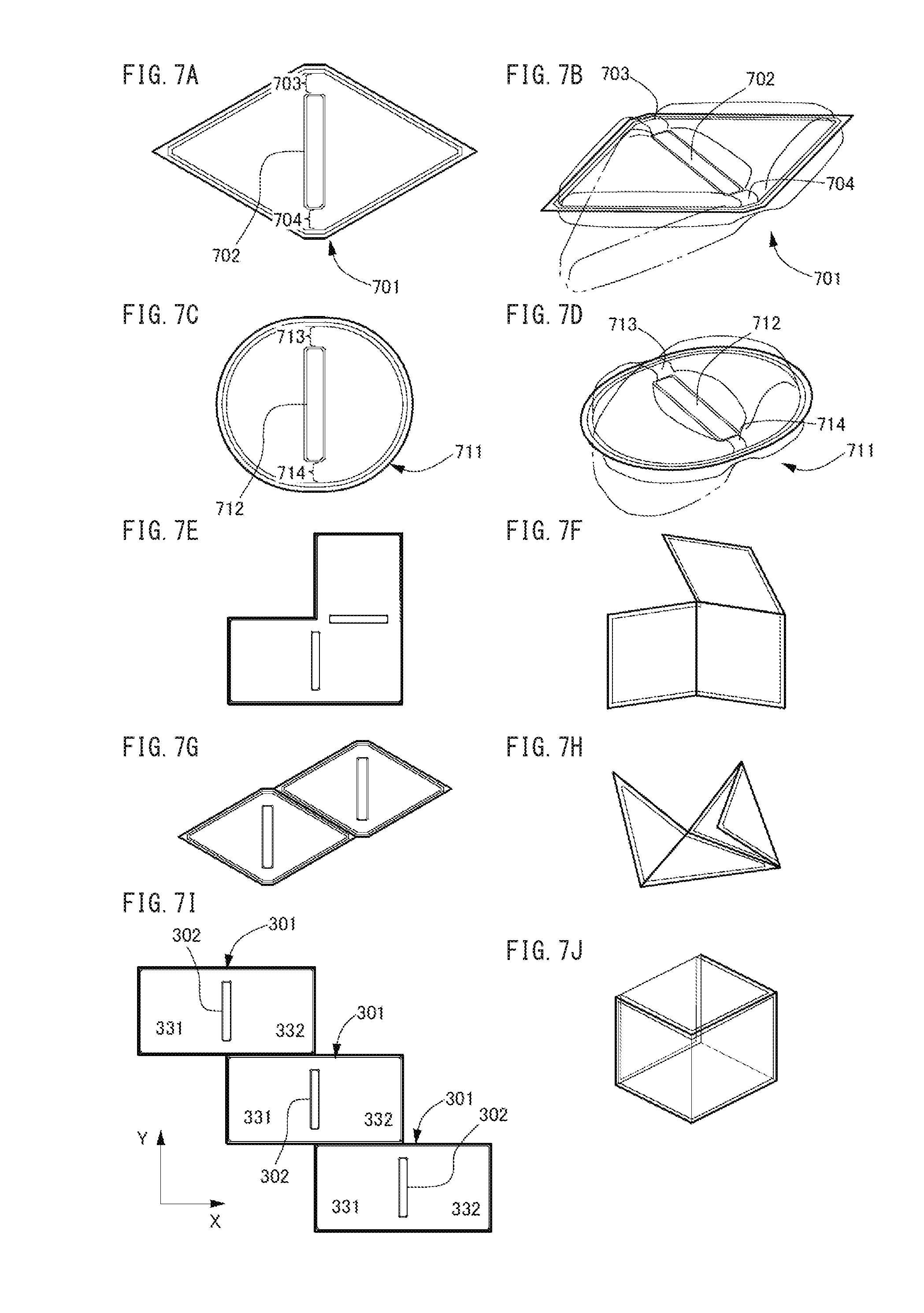
[0018] FIG. 7A is a plan diagram illustrating a case in which the bag has a triangular shape in plan view, FIG. 7B is a perspective diagram illustrating a case in which the bag has a triangular shape in plan view, FIG. 7C is a plan diagram illustrating a case in which the bag has a semi-circular shape in plan view, FIG. 7D is a perspective diagram illustrating a case in which the bag has a semi-circular shape in plan view, FIG. 7E is a plan diagram illustrating a case in which rooms of the bag have rectangular shapes in plan view, FIG. 7F is a perspective diagram illustrating a case in which the rooms have rectangular shapes in plan view, FIG. 7G is a plan diagram illustrating a case in which the rooms have triangular shapes in plan view, FIG. 7H is a perspective diagram illustrating a case in which the rooms have triangular shapes in plan view, FIG. 7I is an elevation diagram in which three bags in FIG. 3A are connected, and FIG. 7J is a perspective view in which the three bags in FIG. 7I are bent at partitions;
[0019] FIGS. 8A, 8B, 8C, and 8D are diagrams in plan view of a case in which the bag has only one duct;
[0020] FIGS. 9A, 9B, and 9C are diagrams in plan view in a case in which the bag includes thickness limiters, and FIG. 9D is a perspective view of the bag in FIG. 9A; and
[0021] FIG. 10A is a diagram illustrating a plan view of the bag, FIG. 10B is a diagram illustrating a plan view of a protect sheet, and FIG. 10C is a perspective view of an air cushion including the bag in FIG. 10A and the protect sheet in FIG. 10B.
DETAILED DESCRIPTION
[0022] Hereinafter, one or more embodiments of the present invention will be described with reference to the drawings. However, the scope of the invention is not limited to the disclosed embodiments.
[0023] The following describes an embodiment of the present disclosure, with reference to the drawings.
[Appearance of Image Forming Device]
[0024] FIG. 1A is a perspective view of an appearance of an image forming device to be packed. The image forming device 100 is an in-body sheet-ejection type multi-function peripheral (MFP) that has functions of a scanner, a color copier, and a color printer. On an upper face of a housing containing the MFP 100, the MFP 100 has an auto document feeder (ADF) 110 that is mounted in an openable and closable manner. At an upper portion of the housing immediately below the ADF 110 is contained a scanner 120; at a lower portion of the housing is contained a printer 130; and at a bottom portion below the printer 130, the MFP 100 has a plurality of paper cassettes 133 that are mounted in a drawable manner. The MFP 100 has a gap DSP between the scanner 120 and the printer 130, and inside the gap DSP is disposed a sheet ejection tray 44. The MFP 100 has, in an innermost portion of the gap DSP, an ejection outlet (not illustrated) from which a sheet is ejected onto the sheet ejection tray 44. The MFP 100 has an operation panel 51 at a portion of a front of the housing adjacent to the gap DSP, a touch panel embedded in a front face of the operation panel 51, and various mechanical push buttons arranged around the touch panel. The touch panel displays graphical user interface (GUI) screens such as an operation screen and a screen for inputting various information. The operation panel 51 receives user input through gadgets such as icons, virtual buttons, menus, tool bars, or the like displayed on the touch panel and the push buttons around the touch panel.
[Packing of Image Forming Device]
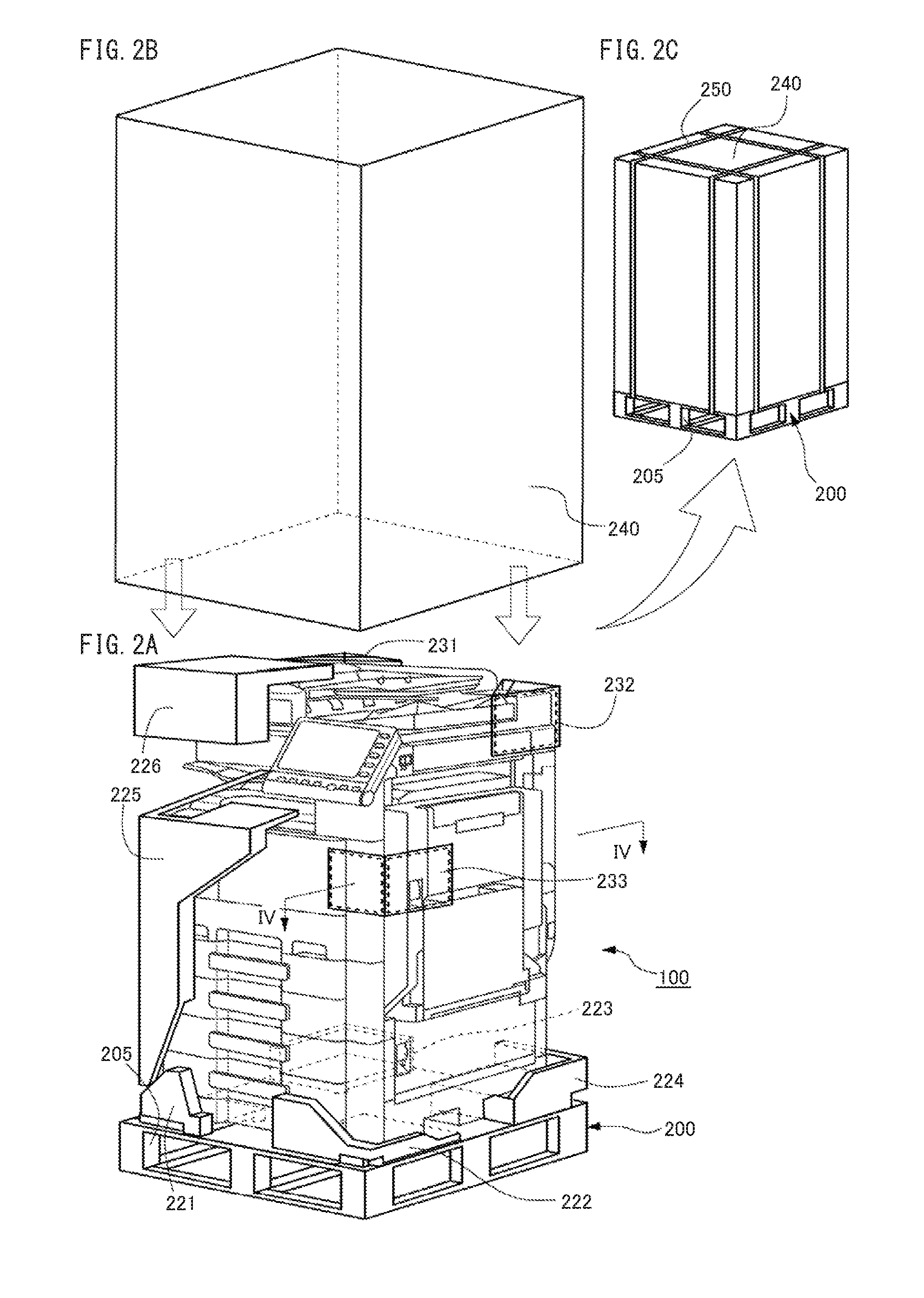
[0025] FIG. 1B is a perspective view of an appearance of components of the packaging material that are placed around an upper portion of the MFP 100 in FIG. 1A. FIG. 1C is a perspective view of an appearance of components of the packing material that are placed around a lower portion of the MFP 100 in FIG. 1A. FIG. 2A a perspective view of an appearance of the MFP 100 with the packaging material placed therearound. The packing material includes a palette 200, a pad 210, block-shaped cushions 221-226, and air cushions 231-233 in the order from the bottom to the top of the MFP 100. The palette 200 is a member commonly used in logistics industry for a platform on which a package is placed, when loaded, unloaded, transported, and stored. The palette is a rectangular plate made of wood, hard plastic, or metal, which has a unified size of 1100 mm.times.1100 mm.times.144 mm according to the Japanese Industrial Standards (JIS). The MFP 100 has the bottom face smaller than the top face of the palette 200, and therefore, the palette 200 allows the MFP 100 to be placed thereon. The pad 210 is a cushion in a thin-plate shape, and is substantially the same size as the top face of the palette 200. The pad 210 is made of high elasticity or plasticity material, such as cardboard, plywood, hard plastic, or foamed plastic. The pad 210 has cutouts 211-214 at its four corners; when the pad 210 is fit onto the top face of the palette 200, the cutouts 211-214 abut on the side faces of positioning pieces 201-204, which protrude upwards from four corners of the top face of the palette 200. The block-shaped cushions 221-226 are made of foamed plastic such as styrene foam, and are molded in advance according to the profile of the MFP 100 such that the block-shaped cushions 221-226 are closely attached to the surface of the MFP 100. Specifically, as illustrated in FIG. 2A, the first through fourth cushions 221-224 completely cover the four corners of the bottom face of the MFP 100 one by one. Each cushion 221-224 has a protrusion 22T downwards from its bottom face. The protrusions 22T are inserted into holes 21H in the top face of the pad 210 to fix the cushions 221-224 to the pad 210. The fifth cushion 225 covers a vertical edge 102 of the MFP 100 that extend directly below from an outer corner of the ejection tray 44 of the MFP 100; the fifth cushion 225 also covers, throughout the vertical edge 102, rims of the front and side faces of the MFP 100 that share the vertical edge 102. Above the vertical edge 102, the sixth cushion 226 covers the entirety of a corner shared by the ADF 110 and the scanner 120. The first air cushion 231 and the second air cushion 232 are disposed at two different corners of the ADF 110 near the back of the MFP 100. Since the operation panel 51 is located at a remaining corner of the ADF 110, the third air cushion 233 covers, instead of this corner of the ADF 110, an upper portion of the vertical edge 103 of the MFP 100 extending directly under the corner of the ADF 110; the third air cushion 233 also covers upper rims of the front and side faces of the MFP 100 that share the vertical edge 103.
[0026] FIG. 2B is a perspective view of an appearance of an outer case 240, which is a component of the packing material used for the MFP 100. FIG. 2C is a perspective view of an appearance of the MFP 100 over which the outer case 240 in FIG. 2B is covered. Around the MFP 100 are arranged other components 200, 210, 221-226, and 231-233 of the packing material in FIG. 2A. The outer case 240 is a box that is separate wall members assembled or a single wall member bent into a shape of cuboid. The wall members are made of high-strength and light-weight material such as hard cardboard, wood, or hard plastic. The outer case 240 is bottomless, and its hollow has a size (length.times.width.times.height) slightly larger than the MFP 100. Accordingly, when the outer case 240 is covered over the MFP 100 in FIG. 2A, and then the palette 200 closes the opening of the outer case 240, as illustrated in FIG. 2C, the entirety of the MFP 100 is hidden inside the outer case 240 and cannot be seen from the outside. In this state, the outer case 240 is bound to the palette 200 with fixing bands 250, which are belts or straps made of metal or soft plastic, such as a steel belt or a wire. Packing of the MFP 100 is thus completed. Then, the MFP 100 is conveyed by application of a force to the palette 200, for example, by hanging with forks of a forklift or a carriage inserted into holes 205 in side faces of the palette 200. On the top face of the outer case 240, another outer case containing another MFP (without a palette) may be loaded. The upper MFP weights the palette 200 through the lower outer case 240. The lower outer case 240 has a stiffness high enough to enable the two MFPs to be transported without being deformed; i.e. the lower outer case 240 can bear the weight of two or more MFPs.
[0027] The first through sixth cushions 221-226 have sizes designed as follows. As illustrated in FIG. 2A, the cushions put the outer surfaces on the inner walls of the outer case 240, when contained in the outer case 240 along with the MFP 100. The cushions receive, from portions of the inner walls of the outer case 240 contacting the outer surfaces of the cushions, pressure to the outer faces of the MFP 100, which is based on stress in the outer case 240 due to contact with the outer surfaces of the cushions. This stress prevents the outer case 240 from deformation caused by the contact with the outer surfaces of the cushions, due to the high stiffness of the outer case 240. The first through fourth cushions 221-224 bear the weight of the MFP 100 and support the bottom face of the MFP 100 at its four corners. At the same time, the cushions 221-224 are horizontally fixed due to pressure from the inner walls of the outer case 240, therefore stabilizing the MFP 100 inside the outer case 240, specifically in the horizontal direction. Further, the cushions 221-224, in cooperation with the pad 210, absorb external vibrations and shocks that the palette 200 receives, specifically in the vertical direction, and mitigate components of the vibrations and shocks transmitted to the MFP 100. The fifth cushion 225 uses the pressure from the inner wall of the outer case 240 to press the paper cassettes 133 and front doors of the MFP 100 from outside and prevent them from accidentally opening due to external vibrations and shocks. The fifth cushion 225 also absorbs external vibrations and shocks that the outer case 240 receives, and mitigates components of the vibrations and shocks transmitted to the MFP 100. The sixth cushion 226 uses the pressure from the inner walls of the outer case 240 to press the ADF 110 from above and prevent the ADF 110 from accidentally opening due to external vibrations and shocks. The sixth cushion 226 also absorbs external vibrations and shocks that the outer case 240 receives, and mitigates components of the vibration and shocks transmitted to the MFP 100. As described above, the first through sixth cushions 221-226 have roles of supporting and fixing the MFP 100 within the outer case 240. Accordingly, the cushions 221-226 need to have a high stiffness in addition to their buffering capability, and therefore are made of foamed plastic, like conventional ones.
[0028] The air cushions 231-233 include rooms containing gas such as air. This causes the cushions 231-233 to contact both the surface of the MFP 100 and the inner wall of the outer case 240, when contained in the outer case 240 along with the MFP 100, as illustrated in FIG. 2A. Under these conditions, the cushions 231-233 receive, from portions of the inner wall of the outer case 240 that the outer surfaces of the cushions 231-233 contact, pressure to the outer surface of the MFP 100. This pressure is based on stress in the outer case 240 caused by gas pressure of the rooms. This stress prevents the outer case 240 from deformation caused by the gas pressure of the rooms by the high stiffness of the outer case 240. The pressure from the outer case 240 keeps the cushions 231-233 in contact with both the MFP 100 and the outer case 240 in gaps therebetween without displacement. When the side faces of the outer case 240 receive external vibrations and shocks, gas inside the air cushions 231-233 not only decreases its volume but also flows within the cushions by increase in pressure from the inner wall of the outer case 240 caused by the vibrations and shocks. The volume decrease and gas flow convert a part of energy of the vibrations and shocks into heat to be dissipated into the environment, thus mitigating the component of the vibrations and shocks transmitted to the MFP 100.
[Structure of Air Cushions]
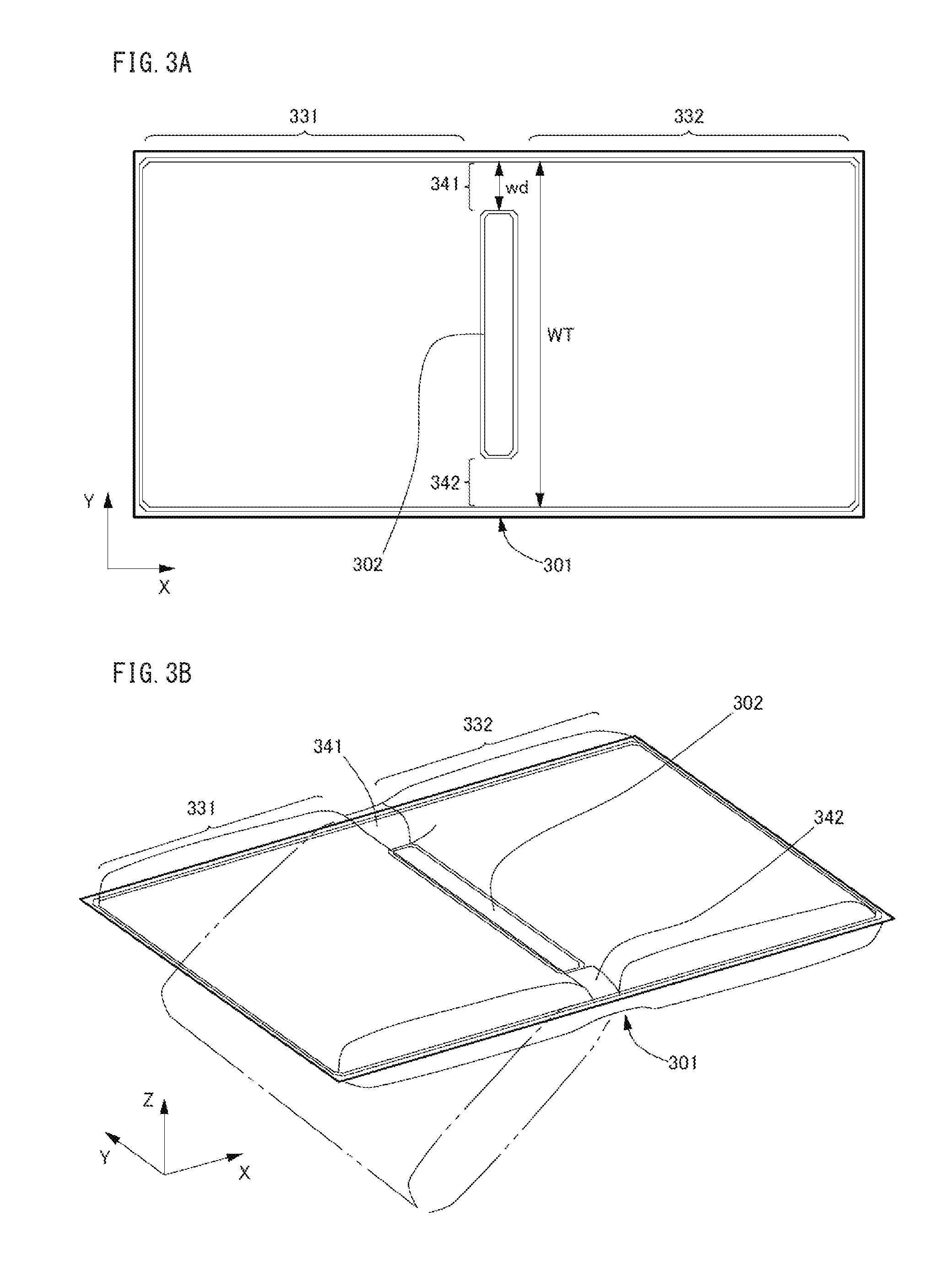
[0029] FIG. 3A is a plan view of the third air cushion 233, and FIG. 3B is a perspective view of the third air cushion 233. Other air cushions 231 and 232 each have a structure similar to that of the third air cushion 233 except for a bar described later. The third air cushion 233 includes a bag 301, which has a structure of two overlaid sheets having the same size and rectangular shape. The sheets are made of soft plastic, for example, laminate sheets of nylon and polyethylene layers. The bag 301 has, for example, the nylon layer in its inside and the polyethylene layer in its outside, and the entirety of circumferences of the sheets is hermetically heat-sealed. Since the nylon layer has great gas shielding property and strength, and the polyethylene layer has great thermal processability, the bag 301 is easily processed through heat-sealing and has great strength and air-tightness. The bag 301 seals therein gas such as air, and a filling ratio of the gas is higher than 50% but lower than 100%. The term "filling ratio" means the ratio of the cross-section area of the bag hermetically containing gas (including its inner space) to the area of a perfect circle whose circumferential length is the same as that of the cross-section of the bag to which no tension is applied. Inside the bag 301, a linear partition 302 extends at the central portion in the longer-edge direction of the bag 301 (X-axis direction in FIG. 3A and FIG. 3B) along its shorter-edge direction (Y-axis direction). The partition 302 is a region where the two inner faces of the bag 301 opposed to each other across the space inside the bag 301 are partially heat-sealed. The partition 302 divides the space inside the bag 301 into a first room 331 and a second room 332, which are of the same capacity. The partition 302 is shorter than the shorter edge of the bag 301, and therefore, gaps 341 and 342 between the longitudinal edges of the partition 302 and the longer edges of the bag 301 function as ducts connecting between the first room 331 and the second room 332. As illustrated in FIG. 3B, the partition 302 is thinner than both the first room 331 and the second room 332 (shorter in Z-axis direction). Accordingly, the bag 301 easily bends at the partition 302.
[0030] FIG. 4A is a cross-sectional diagram of the outer case 240 and the third air cushion 233, taken along line IV-IV in FIG. 2A. When the third air cushion 233 is used as a packing material for the MFP 100, as illustrated in FIG. 2A, its bag 301 bends at the partition 302 placed along the vertical edge 103 of the MFP 100, and then contacts the front face 104 and a side face 105 of the MFP 100, which share a vertical edge 103 of the MFP 100, at the outer surface of the first room 331 and the outer surface of the second room 332, respectively. The outer surfaces of the rooms 331 and 332 are further pressed onto the front face 104 and the side face 105 of the MFP 100, respectively, through pressure from the inner wall of the outer case 240, and therefore, the rooms 331 and 332 are compressed until the gas pressure of the rooms 331 and 332 is balanced with the pressure from the inner wall of the outer case 240. Under this condition, for example, the front wall 241 of the outer case 240 receives a shock force FSH from the outside, and is compressed by the shock force FSH. Then, the first room 331 is compressed by increasing pressure from an inner face of the front wall 241 to decrease the volume of the gas inside. Thus, the energy applied from the outside by the shock force FSH is absorbed by the front wall 241 of the outer case 240 as its elastic energy, and further, dissipates from the gas inside the first room 331 as heat generated by its volume decrease. When the shock force FSH is stronger, a portion PGS of the gas flows from the first room 331 into the ducts 341 and 342, and, against frictional forces that the gas PGS receives inside the ducts 341 and 342, and pressure that a side wall 242 of the outer case 240 applies to the outer surface of the second room 332, flows through the ducts 341 and 342 into the second room 332. Accordingly, the pressure PRS inside the second room 332 increases and pushes back the side wall 242 of the outer case 240, thereby causing the side wall 242 to elastically deform. Thus, the energy applied from the outside by the shock force FSH further dissipates as frictional heat generated when gas flow PGS passes through the ducts 341 and 342, and in addition, is absorbed by the side wall 242 of the outer case 240 as its elastic energy. This buffering function by cooperation of the third air cushion 233 and the outer case 240 mitigates, of the energy applied from the outside by the shock force FSH, a portion reaching the front face 104 of the MFP 100.
[0031] FIG. 4B is a cross-sectional diagram of the outer case 240 and the third air cushion 233, illustrating a state after removal of the shock force FSH in FIG. 4A. When the shock force FSH is removed, the front wall 241 and the side wall 242 of the outer case 240 each release the elastic energy stored therein and return from deformed states to original flat states. Since the second room 332 is then compressed by the restoring force RCF of the side wall 242, a portion PGS of the gas returns from the second room 332 through the ducts 341 and 342 to the first room 331. Thus, the rooms 331 and 332 return to states with the same pressure and volume of the gas. This restoration function by cooperation of the third air cushion 233 and the outer case 240 enables them to completely regain their buffering capacity even after the removal of the shock.
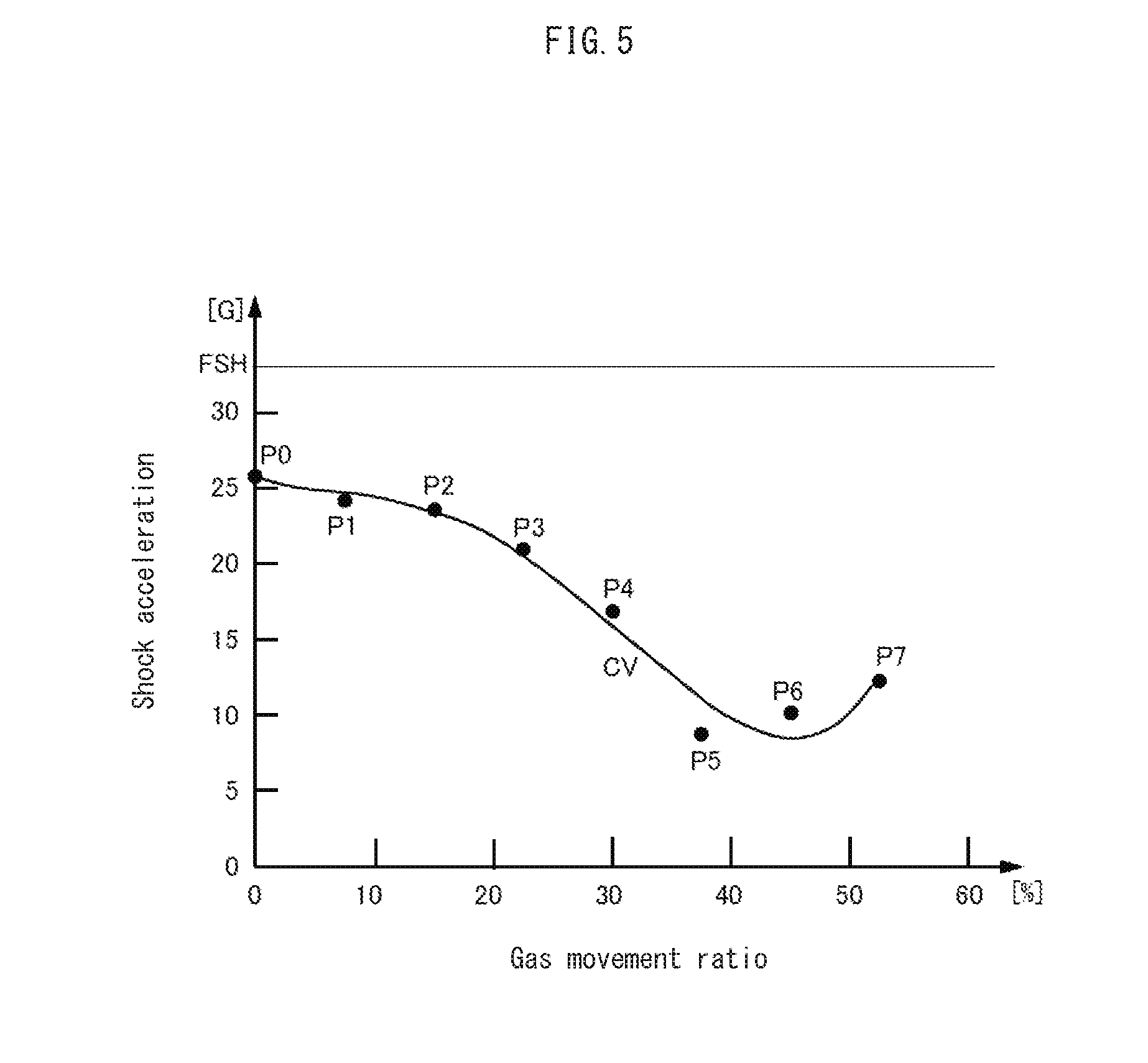
[0032] FIG. 5 is a graph of the buffering capacity of the third air cushion 233 in the state in FIG. 4A. The vertical axis of this graph expresses an acceleration that the front face 104 of the MFP 100 receives by a certain shock force FSH (hereinafter referred to as "shock acceleration") as a ratio to the gravitational acceleration (1 G.apprxeq.9.8 m/s.sup.2). The horizontal axis of this graph expresses a rate of the gas that moves from the first room 331 to the second room 332 in response to the shock force FSH, i.e. a movement ratio of the gas, as a change of the filling ratio of the gas inside the first room 331. Each point P0, P1, . . . , or P7 plotted in this graph is a measurement point whose coordinates are measurement values of the movement ratio and shock acceleration. The measurement points P0-P7 are obtained through experiments performed at the ratios, which are increased from 0% by 5% increments, of the width wd of the duct 341 to the length WT of a boundary between the first room 331 and the second room 332 in the longitudinal direction (Y-axis direction) of the partition 302 (see FIG. 3A.) The curve CV expressed by the graph smoothly interpolates the measurement points P0-P7. In the experiments, air is used as the gas inside the bag 301, and the filling ratio of the air in the bag 301 is set to 60%. Accordingly, 60% is the common initial value of the filling ratios of the air in the first room 331 and the second room 332.
[0033] The points P0-P2 show that, since the width of the duct 341 is 10% or less of the length WT of the longitudinal boundary between the rooms 331 and 332, the shock acceleration is mitigated to 25 G even when the air moving from the first room 331 to the second room 332 is 15% or less of the entirety of the gas inside the first room 331. This shows that air compression alone provides the first room 331 with a relatively high buffering capacity. The points P3-P6 show that, as the width of the duct 341 increases from 15% to 30%, the air moving from the first room 331 to the second room 332 has amounts increasing from 20% to 45%, and the shock acceleration rapidly falls to less than 10 G. This shows movement of the air from the first room 331 to the second room 332 greatly improves the buffering capacity of the first room 331. The range from the point P6 to the point P7 shows that, since the width of the duct 341 increases from 30% to 35%, the air moving from the first room 331 to the second room 332 has amounts exceeding 50%, and the shock acceleration regains 10 G or more. This shows that the first room 331 loses its buffering capacity by air compression since the first room 331 has a remaining amount of the air reduced to 10% or less.
[0034] The graph in FIG. 5 proves the following. The width wd of the duct 341 moderately larger than the length WT of the boundary between the first room 331 and the second room 332 and the moderately high movement ratio of the air from the first room 331 to the second room 332 can sufficiently improve the buffering capacity by cooperation of the third air cushion 233 and the outer case 240. Specifically, the ratio, 5%-30%, of the width wd of the duct 341 to the length WT of the boundary between the rooms and the movement ratio, 15%-45%, of the air between the rooms enhance the buffering capacity by cooperation of the third air cushion 233 and the outer case 240 to a level equal to or greater than the buffering capacity of a block-shaped cushion made of foamed plastic. Maintenance of the movement ratio of the air between the rooms within the range of 15-45% can be achieved when the initial value of the filling ratio of the air in the bag 301, i.e. the common initial value of the filling ratios of the air in the rooms 331 and 332 is set to 55%-85%.
[Bar]
[0035] FIG. 6A is an elevation view that is common to the first air cushion 231 and the second air cushion 232. FIG. 6B is a perspective view of the first air cushion 231 (the second air cushion 232) after assembly. The cushions 231 and 232, except for the third air cushion 233, have bars 234 and 235. The bars are each combination of a tab 234 and a skew portion 235. The tab 234 is a small piece that protrudes from one edge of the first room 331 in the longitudinal (Y-axis) direction of the partition 302. The skew portion 235 is a straight belt that extends obliquely to the longer edge of the bag 301 from the edge of the second room 332 in the longitudinal (Y-axis) direction of the partition 302 on the same side as the tab 234. The tab 234 and the skew portion 235 are both, for example, cut out from an extended portion of one of the two laminate sheets that form the bag 301. The skew portion 235 may be shaped as a bag by another sheet overlaid on the extended portion and hermetically heat-sealed along the periphery of it. The skew portion 235 may contain gas therein. The tab 234 has a hole 236 to engage with a tip protrusion 237 of the skew portion 235. In a state of the bag 301 bending at the partition 302, as illustrated in FIG. 6B, the protrusion 237 of the skew portion 235 engages with the hole 236 of the tab 234. Such a combination 234, 235 forming the bar fixes a bending angle of the bag 301 between the edges of the first room 331 and the second room 332 like an angle brace. As illustrated in FIG. 2A, when the first air cushion 231 and the second air cushion 232 are placed at the corners of the ADF 110, the bar 234, 235 is placed on the top face of the ADF 110 and pressed down on it by the outer case 240. This enables the first air cushion 231 and the second air cushion 232 to be stably held at the corners of the ADF 110.
[Merits of Embodiment]
[0036] As described above, the packing material pertaining to the embodiment of the present disclosure includes the air cushions 231-233. The air cushions 231-233 are placed, for example, at three of eight corners of the MFP 100 to be packed, the three corners of the top face of the MFP 100. These three corners do not require relatively high strength. The air cushions each bend at the partition 302 to contact one face of the MFP 100 at the outer surface of the first room 331 of the bag 301, and to contact the other face of the MFP 100 at the outer surface of the second room 332. To these outer surfaces of the rooms 331 and 332, the outer case 240 applies pressure in the directions towards the respective faces of the MFP 100. Since the filling ratio of the gas in the bag 301 is lower than 100%, a shock force FSH that the first room 331 receives from the outside of the outer case 240 moves the gas PGS from the first room 331 to the second room 332 against the pressure applied by the outer case 240 to the second room 332. This movement causes the pressure inside the second room 332 to increase and push back the side wall 242 of the outer case 240, thereby deforming the side wall 242 elastically. Thus, energy applied from the outside by the shock force FSH dissipates as frictional heat when the gas flow PGS passes through the ducts 341 and 342, and is absorbed by the side wall 242 of the outer case 240 as its elastic energy. This buffering function by cooperation of the air cushions and the outer case 240 mitigates, of the energy from the outside, a portion transmitted to the front face of the MFP 100. When the shock force FSH is removed, the side wall 242 of the outer case 240 releases the elastic energy stored therein and returns from a deformed state to an original flat one. The restoring force RCF of the outer case 240 compresses the second room 332, and therefore, gas returns from the second room 332 to the first room 331. This restoration function by cooperation of the air cushions and the outer case 240 causes the first room 331 to surely regain its buffering capacity even after the shock was received. As described above, the packing material pertaining to the embodiment of the present disclosure ensures that gas receives sufficiently high resistance when moving between the rooms 331 and 332 of the cushions 231-233 by external forces, and that the cushions 231-233 restore their buffering capacities when released from the external forces without increase in number of components and complication of the structure.
[0037] In addition to the above-mentioned merits, the packing material pertaining to the embodiment has the following merits. Firstly, if the air cushions 231-233 have the same thickness as a block-shaped cushion made of foamed plastic, the packing material can achieve buffering capacity larger than the block-shaped cushion; if the packing material have the same buffering capacity as the block-shaped cushion, the air cushions 231-233 can consume a smaller amount of resin than the block-shaped cushion. In this sense, the air cushions 231-233 are environmentally friendly. Secondly, when disposed, the air cushions 231-233 allow their volume to be reduced up to around 1%, by letting out the air of the bag 301. Accordingly, the air cushions 231-233 are advantageous to reduction of packing materials to be disposed. Thirdly, being made of soft plastic and in a sheet-like shape as illustrated in FIG. 3A, the air cushions 231-233 can be stored in a compact manner, for example, by being rolled into a cylinder. Accordingly, the packing material of the present disclosure has an advantage in reduction of its storage space. Fourthly, the ducts 331 and 332 need no components for increasing air resistance such as check valves, and therefore the air cushions 231-233 still have a small number of components and a simple structure. Fifthly, the air cushions 231-233 allow the buffering capacity of the packing material to be controlled by merely adjusting the ratio of the width wd of the duct 341 to the length WT of the boundary between the first room 331 and the second room 332, as illustrated by the measurement points P0-P7 in FIG. 5. Accordingly, the air cushions 231-233 have great flexibility in design.
MODIFICATIONS
[0038] (A) The image forming device 100 in FIG. 1 is the MFP. Alternatively, the image forming device to be packed may be a single-function machine such as a printer, a copier, or a facsimile, or an optional machine such as a sheet feeder or a finisher. An object to be packed may be, for example, an electronic device such as a personal computer, a server, or the like, a large electrical home appliance such as a laundry machine or refrigerator, a machine tool such as a lathe, or a part or finished product of industrial robots.
[0039] (B) In the air cushion 233 in FIG. 3A, the planar shape of the bag 301 is a rectangle. Alternatively, the planar shape of a bag may be a polygon such as a triangle, or include a curve in its circumference, such as a semi-circle.
[0040] FIGS. 7A and 7B are plan and perspective views of a bag whose planar shape is a triangle, respectively. FIGS. 7C and 7D are plan and perspective views of a bag whose planar shape is a semi-circle, respectively. In either of the bags, a linear partition 702 or 712 extends at the center of the bag 701 or 711 to divide the inside of the bag into two rooms of the same capacity. Gaps 703, 704, or 713, 714 between the circumference of the bag and longitudinal ends of the partition function as ducts connecting between the adjacent rooms. As illustrated in FIG. 7B, the bag 701 easily bends at the partition 702; as illustrated in FIG. 7D, the bag 711 easily bends at the partition 712. Even when the bag has such planar shapes, the air cushion can achieve a great buffering capacity due to cooperation with the outer case, in a manner similar to the above-described embodiment.
[0041] (C) The bars 234, 235 in FIGS. 6A and 6B have a shape of a belt. Alternatively, the bar may be a triangular or rectangular film, and may connect the entirety of an edge of the first room 331 with the entirety of an edge of the second room 332.
[0042] Instead of the bar, a third room may be provided. The third room, for example, may have the same size as the first room 331 and the second room 332, share an edge with either of the first and second rooms and, through a duct in the shared edge, be connected to the room.
[0043] FIGS. 7E and 7F are plan and perspective views of the rooms whose planar shapes are rectangles, respectively. FIGS. 7G and 7H are plan and perspective views of rooms whose planar shapes are triangles, respectively. In any of the rooms, each edge shared by two adjacent rooms includes a linear partition heat-sealed. Further, one or both of the two partitions may include a duct connecting between the adjacent rooms.
[0044] A plurality of the bags 301 may be connected in a bendable manner in order to protect a face in a shape more complex than the corners of the ADF 110.
[0045] FIG. 7I is an elevation view of a connection of three of the bags 301 in FIG. 3A, and FIG. 7J is a perspective view of the three bags 301 in FIG. 7I bent at partitions. As illustrated in FIG. 7I, the second room 332 of each bag and the first room 331 of an adjacent bag are connected such that they share an edge in the longer-edge (X-axis) direction of the bags. This enables, as illustrated in FIG. 7J, the six rooms to cover a space from all the three orthogonal directions: back-forth, up-down, and left-right directions. Each joint between the bags may be entirely hermetic by heat-seal to divide the two adjacent rooms, or may include a duct to connect between the two adjacent rooms in a manner similar to the partition.
[0046] (D) The bag 301 in FIG. 3A has the ducts 341 and 342 at the ends of the partition 302. Alternatively, the bag 301 may have a single duct, or three or more ducts. Irrespective of the number of ducts, cooperation of the third air cushion 233 and the outer case 240 achieves sufficiently high buffering capacity as long as the ratio of the total widths of the ducts to the length of the boundary between the first room 331 and the second room 332 is 5%-30% and the movement ratio of air between the rooms is 15%-45%.
[0047] FIGS. 8A, 8B, 8C, and 8D are plan views of bags with a single duct. In FIGS. 8A and 8B, a partition 802 has an end 803 in one longer edge of the bag 301, and has a duct 841 between the other end of the partition 802 and the other longer edge of the bag 301. The end 803 of the partition 802 may be heat-sealed, as illustrated in FIG. 8A, or may be open, as illustrated in FIG. 8B. In FIGS. 8C and 8D, one partition 812 has a base end 813 in one longer edge of the bag 301, and another partition 822 has a base end 823 in the other longer edge of the bag 301. The partitions 812 and 822 extend from their respective longer edges of the bag 301 in its shorter edge direction, and the other ends of the partitions 812 and 822 are placed across a space at the center of the bag 301 to form the duct 842. The base end 813 of the partition 812 and the base end 823 of the partition 822 may be heat-sealed, as illustrated in FIG. 8C, or may be open, as illustrated in FIG. 8D.
[0048] (E) Welded areas inside the bag 301 in FIG. 3A include only the partition 302. In addition to the partition 302, the bag 301 may have a thickness limiter in at least one of the rooms. In this case, the thickness limiter limits thickness of the room.
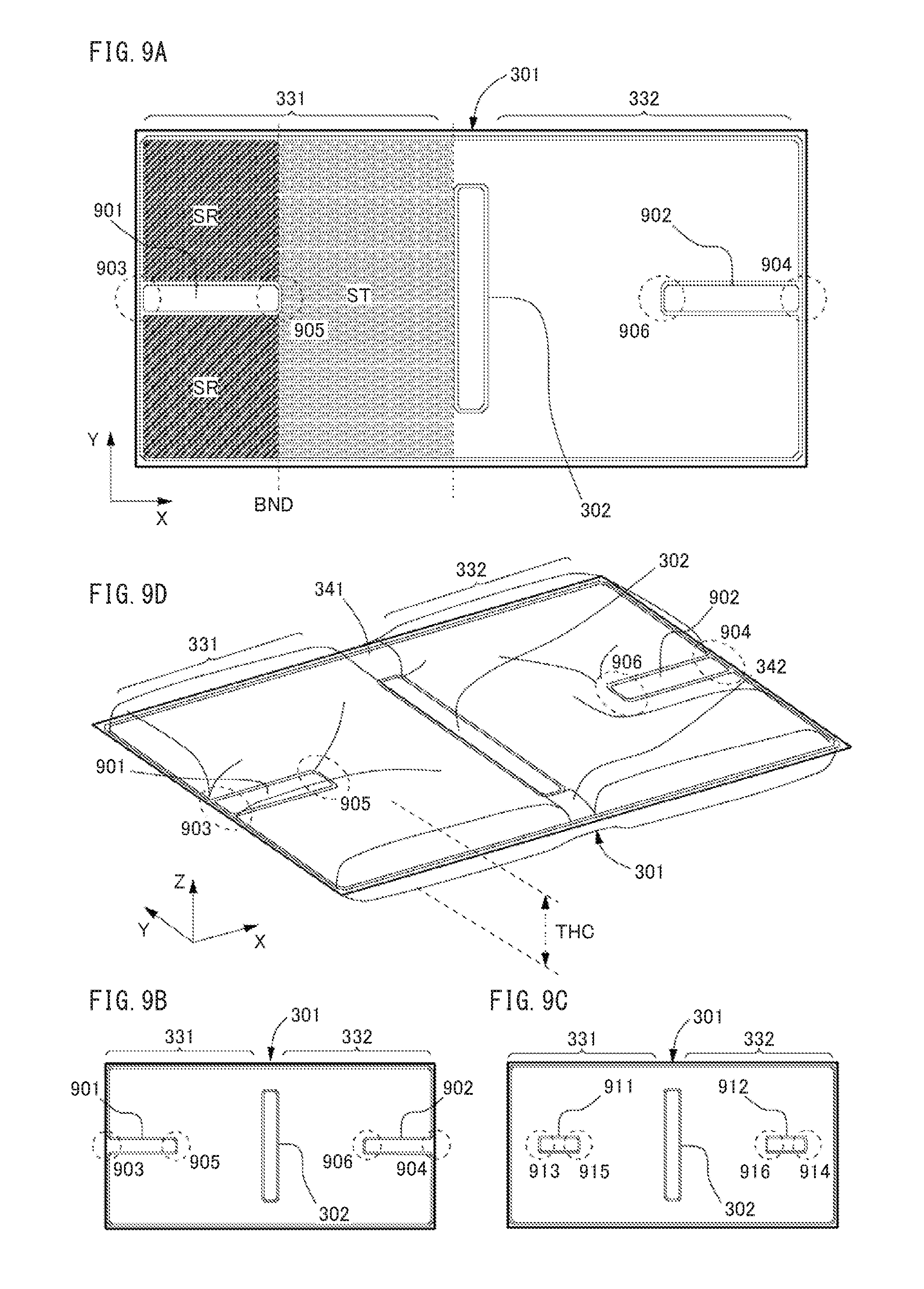
[0049] FIGS. 9A, 9B, and 9C are plan views of the bag 301 including thickness limiters. The thickness limiters are areas in which the bag 301 is compressed and its two inner faces opposed across the space inside the first room 331 or the second room 332 are heat-sealed. The rooms 331 and 332 include thickness limiters one by one, which are symmetric with respect to the partition 302. As illustrated in FIGS. 9A and 9B, the thickness limiters 901, 902 extend in the longer-edge (X-axis) direction of the bag 301 from their respective base ends 903, 904 at the centers of the shorter edges of the bag 301 to their respective tip ends 905, 906 in central portions of the rooms 331, 332. The base ends 903, 904 of the thickness limiters 901, 902 may be heat-sealed or open, as illustrated in FIG. 9A or 9B, respectively. The thickness limiters 911 and 912 in FIG. 9C differ from the thickness limiters 901 and 902 in FIGS. 9A and 9B in that the base ends 913 and 914 are distant from the shorter edges of the bag 301.
[0050] FIG. 9D is a perspective view of the bag 301 in FIG. 9A. The thickness limiters 901 and 902 are heat-sealed to be thin, and therefore, prevent the rooms 331 and 332 from swelling by the gas in the bag 301 and limit the thickness THC of the rooms, which is adjustable by the areas of the thickness limiters 901 and 902. Note that the thickness limiter may be disposed in only one of the rooms.
[0051] Advantageously, the thickness limiters 901 and 902 are designed to have lengths in the longer-edge (X-axis) direction of the bag 301 that satisfy the following conditions. A region SR in the first room 331 is referred to as a "standard region," (see the region expressed by oblique lines in FIG. 9A.) The region SR is located, with respect to the partition 302, on the opposite side of a straight line BND that passes through the end 905 of the thickness limiter 901 closest to the partition 302, i.e. the tip 905 of it, and that is parallel with the partition 302. A capacity ratio of the standard region SR to the entirety ST of the first room 331 (i.e. the region expressed by dots in FIG. 9A,) equals the filling ratio of gas in the bag 301. The thickness limiter 902 of the second room 332 is designed to have a length satisfying the above-described conditions. When these conditions are satisfied, a judgment on whether the filling ratio of gas in the first room 331 is proper or not in the process of sealing gas into the bag 301, can be made by whether the boundary of a swelling, which appears when gas in the first room 331 is pushed from the partition 302 in the longer-edge (X-axis) direction of the bag 301, coincides with the boundary BND of the standard region SR or not.
[0052] Circumferences of the bag 301, the partition 302, and the thickness limiters 901 and 902 are hermetically heat-sealed. Alternatively, the hermetical sealing may be achieved by other welding processes such as ultrasonic welding, or by using adhesive.
[0053] (F) The air cushion 233 pertaining to the present disclosure may further include a protect sheet. The protect sheet is, for example, a sheet-like member made of a high-strength resin such as polyethylene terephthalate (PET).
[0054] FIGS. 10A and 10B are plan views of the bag 301 and a protect sheet A10, respectively. FIG. 10C is a perspective view of an air cushion A33 including the bag 301 and the protect sheet A10. The protect sheet A10, which has the same shape and size as the bag 301, is placed between the bag 301 and an outer face of the outer case 240 or the MFP 100. This provides the bag 301 with an improved abrasion resistance against the inner wall of the outer case 240 or the outer surface of the MFP 100. As illustrated in FIG. 10A, the bag 301 includes angular protrusions A11 in the partition 302 and the thickness limiters 901 and 902. The angular protrusions A11 project from the bag 301 toward the protect sheet A10. As illustrated in FIG. 10B, the protect sheet A10 includes U-shaped protrusions A12 in its one face. The U-shaped protrusions A12 project from the protect sheet A10 toward the bag 301. When the bag 301 and the protect sheet A10 are overlaid, as illustrated in FIG. 10C, the angular protrusions A11 fit inside the U-shaped protrusions A12, as expressed by broken lines in FIG. 10B. This enables the protect sheet A10 to be stably coupled with the bag 301. Note that coupling of the bag 301 and the protect sheet A10 allows alternative known coupling or fitting structures such as a hook or a snap.
[Supplement]
[0055] As described above, the packing material pertaining to the present disclosure has the cushion bending at the partition and putting the outer surfaces of the first and second rooms of the bag onto the two different outer faces of the object. The outer case applies pressure to the outer surfaces of the first and second rooms in directions toward the outer faces of the object. Under these conditions, the first room of the bag receives an external force through the outer case, and then gas moves from the first room to the second room against the pressure applied by the outer case to the second room. When the external force is removed, gas returns from the second room to the first room by the pressure applied by the outer case to the second room. The packing material thus enables the gas that the external force moves between the rooms to receive sufficiently high resistance, and in addition, the cushion to surely restore its buffering capacity by release from the external force, without increase in number of its components and complication of its structure.
[0056] Based on the embodiments described above, the invention may be further characterized as follows.
[0057] In the packing material, the bag may be made of a soft plastic sheet, and the partition may be an area where two inner surfaces of the bag, which are placed across a space inside of the bag, are welded or adhered to each other. In the packing material, the outer case may have a higher stiffness than the cushion, and the pressure applied by the outer case to the first and second rooms of the bag may be based on a stress of the outer case preventing its deformation caused by the gas pressure of the first and second rooms.
[0058] In the packing material, a filling ratio of the gas in the bag may be higher than 50% but lower than 100%. Specifically, this filling ratio may be 55%-85%. In the packing material, the ratio of the width of the duct to the length of the boundary between the first and second rooms of the bag may be 5-30%.
[0059] In the packing material, at least one of the first and second rooms of the bag may include a thickness limiter, a collapsed area included in the two inner surfaces of the bag placed across the space inside of the bag, preventing the first or second room from swelling by the contained gas to limit the thickness of the first or second room. Here, the bag may be made of a soft plastic sheet, and the thickness limiter may be an area where the two inner surfaces of the bag placed across the space inside of the bag are welded or adhered to each other. In the packing material, the thickness limiter may be arranged in both the first and second rooms in a manner symmetric with respect to the partition. In the packing material, with respect to a line parallel to the partition and passing through the edge of the thickness limiter closest to the partition, a portion of the first or second room on the opposite side of the partition may have a capacity ratio to the entirety of the first or second room, and the capacity ratio may be equal to the filling ratio of the gas in the bag.
[0060] The packing material may further include a protect sheet placed between the bag of the cushion and the outer case or the object. Here, the partition may include a coupler coupling the protect sheet with the bag. In the packing material, the cushion may further include a bar. When the bag bends at the partition, the bar connects between the edges of the first and second rooms on the same side in the longitudinal direction of the partition to fix an angle of the bag.
[0061] Although one or more embodiments of the present invention have been described and illustrated in detail, the disclosed embodiments are made for the purposes of illustration and example only and not limitation. The scope of the present invention should be interpreted by the terms of the appended claims.
* * * * *
D00000
D00001
D00002
D00003
D00004
D00005
D00006
D00007
D00008
D00009
D00010
XML
uspto.report is an independent third-party trademark research tool that is not affiliated, endorsed, or sponsored by the United States Patent and Trademark Office (USPTO) or any other governmental organization. The information provided by uspto.report is based on publicly available data at the time of writing and is intended for informational purposes only.
While we strive to provide accurate and up-to-date information, we do not guarantee the accuracy, completeness, reliability, or suitability of the information displayed on this site. The use of this site is at your own risk. Any reliance you place on such information is therefore strictly at your own risk.
All official trademark data, including owner information, should be verified by visiting the official USPTO website at www.uspto.gov. This site is not intended to replace professional legal advice and should not be used as a substitute for consulting with a legal professional who is knowledgeable about trademark law.