Lid Ring
Bauer; Sven ; et al.
U.S. patent application number 16/323047 was filed with the patent office on 2019-05-30 for lid ring. This patent application is currently assigned to Amcor Flexibles Singen GMBH. The applicant listed for this patent is Amcor Flexibles Singen GMBH. Invention is credited to Sven Bauer, Andreas Ziegler.
| Application Number | 20190161263 16/323047 |
| Document ID | / |
| Family ID | 56740049 |
| Filed Date | 2019-05-30 |


| United States Patent Application | 20190161263 |
| Kind Code | A1 |
| Bauer; Sven ; et al. | May 30, 2019 |
LID RING
Abstract
A lid ring (7) for sterilizable containers (1) is proposed which is formed from a metal ring (40) coated on both sides with at least one plastic layer (37, 43), a radially outer cut edge and a radially inner flange (31). The radially inner flange (31) is folded back on itself at least once.
| Inventors: | Bauer; Sven; (Steisslingen, DE) ; Ziegler; Andreas; (Stetten, CH) | ||||||||||
| Applicant: |
|
||||||||||
|---|---|---|---|---|---|---|---|---|---|---|---|
| Assignee: | Amcor Flexibles Singen GMBH Singen DE |
||||||||||
| Family ID: | 56740049 | ||||||||||
| Appl. No.: | 16/323047 | ||||||||||
| Filed: | August 2, 2017 | ||||||||||
| PCT Filed: | August 2, 2017 | ||||||||||
| PCT NO: | PCT/EP2017/025227 | ||||||||||
| 371 Date: | February 4, 2019 |
| Current U.S. Class: | 1/1 |
| Current CPC Class: | B65D 77/202 20130101; B65D 2517/0082 20130101; B65D 51/20 20130101; B65D 2517/5054 20130101; B65D 17/502 20130101; B65D 2517/5048 20130101; B65D 53/08 20130101; B21D 51/44 20130101 |
| International Class: | B65D 77/20 20060101 B65D077/20 |
Foreign Application Data
| Date | Code | Application Number |
|---|---|---|
| Aug 2, 2016 | EP | 16020293.3 |
Claims
1. A lid ring comprising; a metal ring having two sides, the metal ring being coated on both sides with at least one plastic layer, the metal ring having a radially outer cut edge and a radially inner flange delimited by a cut edge, with a peripheral sealing zone (30) arranged on the flange characterized in that the radially inner flange is folded back on itself at least once and the fold forming a lid opening is compressed.
2. The lid ring according to claim 1, characterized in that the radially inner flange is folded back on itself at least twice, and the cut edge is enclosed almost substantially air-free by the plastic layers lying on the fold inside.
3. The lid ring according to claim 2, characterized in that a lid ring core wall is formed radially on an outside on the folded radially inner flange with a peripheral sealing zone arranged thereon.
4. The lid ring according to claim 3, characterized in that the radially inner flange is folded back on a side of the flange opposite the sealing zone.
5. The lid ring according to claim 1, characterized in that a metal of the metal ring is selected from the group consisting of steel, tin plate, black plate, aluminium and aluminium alloys.
6. The lid ring according to claim 1, characterized in that a plastic of the plastic layers is selected from the group consisting of polyethylene, polypropylene, polyethylene terephthalate and polyamide.
7. The lid ring according to claim 1, characterized in that a plastic layer has a layer thickness of 5 .mu.m to 100 .mu.m.
8. The lid ring according to claim 1, characterized in that a lid film closing a lid opening is sealed onto the sealing zone.
9. The lid ring according to claim 8, characterized in that the lid film is a composite film selected from the group consisting of plastic-coated aluminium, laminated aluminium, painted aluminium and aluminium-free composite films.
10. The lid ring according to claim 8, characterized in that the lid film is a composite film and has an embossing.
11. The lid ring according to claim 8, characterized in that the lid ring is connected to a container body by a fold connection.
12. A method of producing a lid ring wherein the lid ring includes two sides, a radially cut outer edge and a radially inner flange comprising: single folding the radially inner flange in a radial direction forming a multi-layer flange having a folded region, and wherein after folding, the folded region is also compressed.
13. The method of producing a lid ring according to claim 12, further including coating both sides with a plastic layer, double folding the radially inner flange in the radial direction, forming a multi-layer flange having an inside and the radially cut outer edge is enclosed substantially air-free by the plastic layer lying on the fold inside, and wherein after folding, the folded region is also compressed.
14. The lid ring according to claim 8 characterized in that the lid film is a composite film and has a printing.
Description
CROSS REFERENCE TO RELATED APPLICATIONS
[0001] This application claims the benefit of the priority filing date of PCT Patent application Serial No. PCT/EP2017/025227, titled "LID RING," which has a priority filing date of Aug. 2, 2017 and which includes the same inventor(s). That application is hereby incorporated by reference as if fully set forth herein.
FIELD OF THE TECHNOLOGY
[0002] The present technology concerns a lid ring. The invention technology furthermore concerns a container with a lid and a method for producing the lid ring.
BACKGROUND OF THE TECHNOLOGY
[0003] When packing cans and tins, it is known to provide these with a metal lid permanently attached at the top on the can or container body. The lid which is attached permanently to the container body is formed by a lid ring and a lid film attached to the lid ring by a hot sealing process. Lid films are metal films or composite films. The lid film closes the extraction opening or lid opening for the packaging contents which is formed by the lid ring until opened for the first time. In some cases, an additional lid, preferably made of plastic, is arranged over the metal lid so that the container is reclosable. The latter is however only necessary if the packaging contents are not completely consumed when the container is first opened.
[0004] The requirements for a lid formed from a lid ring and a lid film are the same as those imposed on conventional lids of containers, in particular metal containers. These include resistance to corrosion and resistance to environmental influences and to the filling product. Such filling products are at least sometimes chemically aggressive. In particular in the case of damp or wet filling products such as occur in the field of foodstuff packaging, in particular for retort foodstuff products, corrosion constitutes a problem in relation to the lengthy storage period. Corrosion of the metal packaging material may lead firstly to visual problems in the form of discolouration and secondly to flavour problems. In particular with preserved fish, the transfer of iron oxide into the filling product, sometimes known as ironing, leads to unacceptable flavour changes of the packed foodstuff. To avoid corrosion, the sheet metal forming the container body or lid ring or applied metal film is coated. The inside of the container facing the filling product is usually coated with polyethylene terephthalate (PET) or a lacquer which resists the mechanical stress from production of the container, and also resists aggressive filling products over the desired life of sometimes several years. The outside the container is usually coated with polypropylene or a polypropylene-containing material, since polypropylene is preferably used as a sealing material for the lid film. This means that the side of the lid film which is coated with polypropylene and facing the filling product is sealed on the outside of the polypropylene-coated lid ring facing away from the filling product.
[0005] When the lid opening or extraction opening is punched out of the lid ring blank, an uncoated cut edge is created. Such a cut edge constitutes a certain risk of injury for the user of a corresponding container. With regard to corrosion, such a rough cut edge does not constitute a significant problem for a dry filling product and short storage life. In such cases, however, corrosion does regularly occur and leads to the disadvantageous changes outlined above in the packed foodstuff. A conventional measure which is known for preventing corrosion is to provide the lid ring on its underside facing the filling product with a rolled edge region at the cut edge, known as a retort curl. The cut edge is bent inward in the form of a curl, i.e. towards the side of the filling product, and hence covered by a surface region of the lid ring. The cut edge is therefore usually no longer exposed to the filling product. This solution however entails relatively high costs in production of the corresponding tooling. It is particularly disadvantageous that even minor deviations in production entail an irregular formation of the retort curl and lead to an irregular covering of the cut edge. Also, the retort process, i.e. the sterilization of the filling product by heating and cooling, may lead to the filling product itself, or liquid from the filling product, entering the retort curl.
[0006] WO 01/07330 proposes coating the lid ring which is formed by the sheet metal by powder coating after punching out of the extraction opening. The powder coating of a geometrically very complex body, such as a lid ring, in the desired quality is however difficult to achieve. Coating methods other than powder coating cannot be used.
[0007] WO 2006/092073 describes coating separately the cut edge of a lid ring with a hot-melt material.
BRIEF SUMMARY OF THE TECHNOLOGY
[0008] The disclosed technology may provide a lid ring, or a corresponding lid and corresponding container, which avoids the above-mentioned disadvantages. The technology may also concern a method for producing a lid ring.
[0009] A lid ring may include a metal ring with a radially outer cut edge and a radially inner cut edge forming a lid opening. The metal ring is coated on both sides with at least one plastic layer. The radially inner cut edge is folded back on itself at least once. The fold is also compressed.
[0010] A lid ring may include a metal ring coated on both sides with at least one plastic layer, with a radially outer cut edge and a radially inner flange delimited by a cut edge. A peripheral sealing zone is arranged on the flange. The radially inner flange is folded back on itself at least once and the fold or folded edge of the flange forms a lid opening. The fold is also compressed.
[0011] One or more embodiments may provide a lid ring including a metal ring with a radially outer cut edge and a radially inner flange forming a lid opening. The metal ring is coated on both sides with at least one plastic layer. The radially inner flange is folded back on itself at least twice, whereby the cut edge is enclosed virtually air-free by the plastic layer lying on the inside of the fold. The inside of the fold is the side of the fold with a smaller fold radius.
[0012] Since the radially inner flange is folded back on itself at least twice, the radially inner cut edge is not exposed to contact with the filling product of the container. The cut edge is enclosed virtually air-free and air-tightly by the multiple fold between the plastic layers lying on the top of the lid ring and the bottom of the lid ring. In this way, in a simple fashion, an almost complete protection from corrosion is achieved. This also gives protection from injury when the user handles the container. The radially inner cut edge may be folded both towards the underside of the lid ring, i.e. towards a side facing the filling product, or towards the top of the lid ring, i.e. the side facing away from the filling product. If the radially inner flange is folded back on itself two or more times, the fold is always made towards the same side. Although it is considered within a scope of the technology that one or more folds may be made towards a different side.
[0013] The radially inner flange may be folded back on itself precisely twice. Furthermore, the single or multiple fold of the radially inner flange may be compressed. This gives a better protection of the radially inner cut edge against air and against the filling product.
[0014] In one or more embodiments, a lid ring core wall is formed radially on the outside on the folded radially inner flange with a peripheral sealing zone arranged thereon. The peripheral sealing zone may be arranged on the side of the flange facing away from the filling product, i.e. on the top of the lid ring.
[0015] In one or more embodiments, the radially inner flange is folded back on the side of the flange which is opposite the sealing zone. This means that the folded part of the radially inner flange, or the radially inner cut edge, lies on the side of the flange or lid ring facing towards the filling product and hence on the underside of the lid ring.
[0016] In one or more embodiments, the metal from which the lid ring is formed is selected from aluminium, aluminium alloys, tin plate, black plate and steel. Tin plate is cold-rolled sheet steel, the surface of which is tin-coated. The metal thicknesses are at present usually between 0.1 and 0.5 mm. Black plate is unalloyed steel and is annealed, wherein it reacts with the oxygen in the ambient air and obtains a dark appearance. On hot-rolling, black plate is produced in thicknesses of 1.5 mm and more. Cold-rolled black plate however may be produced more thinly with thicknesses of 0.4 to 1.5 mm, and with a better surface composition.
[0017] In one or more embodiments, the plastic with which the two sides of the lid ring plate are coated is selected from polyethylene, polypropylene, polyethylene terephthalate and polyamide. The top and underside of the lid ring plate may be coated with the same plastic or with different plastics. Usually they are coated with different plastics. The underside of the lid ring plate or lid ring means a side facing towards the filling product. The top side of the lid ring plate or lid ring means the side of the lid ring plate facing away from the filling product.
[0018] The layer thickness of the plastic layers on the underside and top of the lid ring are usually 5 .mu.m to 100 .mu.m, preferably 10 .mu.m to 50 .mu.m, and particularly preferably 20 .mu.m to 40 .mu.m. The same plastic may be arranged on both sides of the lid ring. The plastic layers which are arranged on the underside and top side of the lid ring are however different, since they may have different requirements. Whereas the plastic layer which is arranged on the underside of the lid ring serves to prevent corrosion of the lid ring plate, the plastic layer which is arranged on the top of the lid ring is sealable since the lid film is sealed onto a surface region on the top side of the lid ring, the sealing zone. Polypropylene (PP) or a polypropylene-containing material is used as a sealable plastic for the plastic layer on the top side of the lid ring. The side of the lid film facing the top side of the lid ring may be coated with PP or a polypropylene-containing material.
[0019] In a further aspect of the technology, a lid with a lid ring is described. The lid may include the lid ring and a lid film which is sealed on in the sealing zone of the lid ring and closes the lid opening. The peripheral sealing zone of the lid ring which is arranged on the radially inner flange adjoining the lid ring core wall is arranged on the top side of the lid ring or on the outside of the flange of the lid ring. The side of the lid film facing the filling product and hence the top side of the lid ring is preferably coated with PP or a polypropylene-containing material. It may, however, also be coated with another sealable material.
[0020] In one or more embodiments the lid film of the lid may be made from a plastic-coated aluminium. The aluminium film is usually plastic-coated on one side, wherein polypropylene (PP) is preferably arranged on the sealable side of the lid film. The side which is opposite the sealable side of the lid film is usually printed and/or painted. As well as plastic-coated aluminium composite films, other composite films may be used as lid films, for example painted aluminium films and laminated aluminium films. Also, aluminium-free composite films may be used as lid films. All lid films must, however, have a sealable side in order to be able to create a seal in the sealing zone of the lid ring arranged on the flange.
[0021] In one or more embodiments, the lid film has an embossing or printing. The lid film may simultaneously have both an embossing and a printing. Also, non-embossed lid films may be used.
[0022] In one or more embodiments, a container is described with a lid or lid ring. The lid or lid ring is connected to the container body preferably by a fold connection. The connection between the lid and body may take place in other ways, purely mechanically by form fit and/or friction fit, or by adhesion or hot sealing, or by a combination of such fixing methods.
[0023] A method for producing the lid ring may contain the step of folding the radially inner flange at least once. This gives a region which is folded in the radial direction. A double or multi-layer flange is formed in this folded region. After folding, the fold or folded region is additionally compressed.
[0024] One or more embodiments of the technology may include a step of folding the radially inner flange. The flange is folded at least twice, wherein a flange which is folded three or more times is formed over the region folded in the radial direction, and the cut edge is enclosed almost air-free by the plastic layers lying on the inside of the fold.
[0025] When folded in the radial direction, the flange is bent over or folded, giving a circumferential fold. The radius of the surface region which is folded in the radial direction is usually only a few millimetres, preferably 1 to 3 mm. Due to the at least double folding, the radially inner cut edge is enclosed almost air-free by the plastic layers lying on the inside of the fold.
[0026] After folding, in a further step, the folded region may be additionally compressed to achieve a better seal of the fold against fluids, moisture and air, and hence to give even better protection of the enclosed cut edge against corrosion.
[0027] Further advantages, features and details arise from the following description of preferred embodiments and with reference to the figures. The drawings show purely diagrammatically:
BRIEF DESCRIPTION OF THE DRAWINGS
[0028] FIG. 1 illustrates a perspective view of a container with a tear-off lid;
[0029] FIG. 2 illustrates a perspective partial view of a lid ring blank;
[0030] FIG. 3 illustrates a perspective partial view of a lid ring blank in a further production stage;
[0031] FIG. 4 illustrates a cross-section through a first embodiment of a flange of a lid ring according to the invention;
[0032] FIG. 5 illustrates a cross-section through a second embodiment of a flange of a lid ring according to the invention;
[0033] FIG. 6 illustrates a cross-section through a further embodiment of a flange of a lid ring according to the invention;
[0034] FIG. 7 illustrates a cross-section through the first embodiment of a flange of a lid ring according to the invention with lid film sealed on;
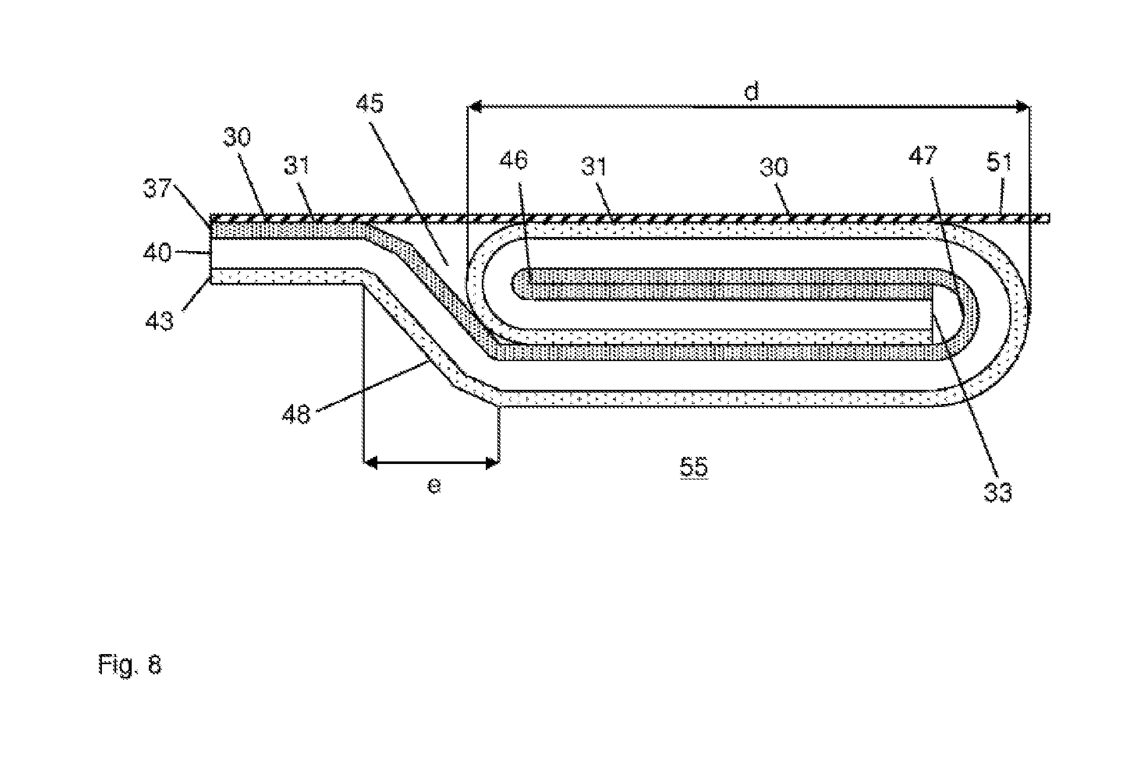
[0035] FIG. 8 illustrates a cross-section through the further embodiment of a flange of a lid ring according to the invention with lid film sealed on.
DETAILED DESCRIPTION OF THE TECHNOLOGY
[0036] FIG. 1 shows a container 1 with a container body 5, a tear-off lid 3 itself comprising a lid ring 7 attached to the container body 5, a lid film 10 and a tear-off tab 15. The lid film 10 closes the extraction opening of the tear-off lid 3. The lid film 10 is provided with a tear-off tab 15 for opening the lid 3.
[0037] FIG. 2 shows a perspective partial view of a lid ring blank 18. For the sake of clarity, only part of a complete lid ring blank 18 is shown. The figure shows the container-side form of the lid ring blank 18 for the fold connection of the lid ring to the container body (not shown). In the radial direction towards the middle of the lid ring blank 18, the folded edge 21 may include a fold radius 22 with which the folded edge 21 transforms into the lid ring core wall 23. The lid ring core wall 23 is followed by the lid ring depth radius 24 which transforms into the lid ring base 27. In this production stage of the lid ring blank, as evident from the figure, no lid or extraction opening has yet been punched out.
[0038] FIG. 3 shows a perspective partial view of a lid ring blank 18 in a further stage of production. The lid ring blank 18 may include, on the container side, a folded edge 21, a fold radius 22, a lid ring core wall 23 and a lid ring depth radius 24. In this production stage, the lid ring blank 18 now has an extraction opening 36. The lid ring depth radius 24 transforms into the flange 31 in the direction of the extraction opening 36. The extraction opening 36 is formed by the radially inner cut edge 33 which is produced during the punching step. A sealing zone 30 is arranged on the flange 31 on the top side of the lid ring.
[0039] FIG. 4 shows in cross-section an extract of a lid ring 7. In particular, the folded region d is shown with the cut edge 33 enclosed virtually air-free. In the embodiment shown, the lid ring has a stacked layer structure with the following layers: a plastic layer 37 arranged on the top side of the lid ring, a metal layer in the form of a metal ring 40, and a plastic layer 43 arranged on the underside of the lid ring. The plastic layer which is arranged on the underside of the lid ring faces the filling product space (not shown), and the plastic layer on the top side of the lid ring is the side of the lid ring 7 facing away from the filling product space and hence towards the outside of the container 1. In this embodiment, the radially inner flange 31 has been folded back on itself twice. Folding took place twice towards the underside of the lid ring, so that the enclosed cut edge 33 comes to lie on the side of the lid ring 7 facing the filling product space. The flange 31 is thus formed in three layers in the folded region d. On the top side of the lid ring, the sealing zone 30 is also arranged which extends beyond the folded region d up to maximally as far as the lid ring core wall (not shown). The cut edge 33 is enclosed almost air-free by the plastic layers 37, 43 lying on the fold inside 46, 47.
[0040] FIG. 5 shows in cross-section an extract of a lid ring 7. In this embodiment, the double fold of the flange takes place towards the lid ring top side, so that the enclosed cut edge 33 comes to lie on the side of the lid ring 7 facing away from the filling product space (not shown). In the folded region d, the flange 31 is again formed in three layers. Since now in the folded region d, the plastic layer 43 which is arranged on the inside of the lid ring facing the filling product space comes to lie on the outside of the lid ring, the plastic selected is preferably also sealable. If the folded region d has a sufficient radius, the sealing zone 30 may be limited to the folded region d. It is, however, also possible for the sealing zone 30 to extend beyond the folded region onto the further part of the flange 31 on the outside in the radial direction, up to maximally as far as the lid ring core wall (not shown). In this variant, the sealing zone 30 is, however, interrupted by a gap 45.
[0041] FIG. 6 shows in cross-section an extract of a lid ring 7. As in the embodiment shown in FIG. 5, the radially inner flange 31 is folded back twice onto the top side of the lid ring. By way of a shoulder 48 in region e, corresponding to double the thickness of the lid ring 7 which is plastic-coated on both sides, in the folded region d the lid ring top side comes to lie in the same plane as the radially outer region of the flange 31. The sealing zone 30 can thus in a simple fashion again extend over the entire radial length of the flange 31 up to maximally as far as the lid ring core wall (not shown). In the region of the shoulder 48, the sealing zone 30 is interrupted by a gap 45.
[0042] FIG. 7 shows lid ring 7 according to FIG. 4, wherein this again is shown in extract. In the sealing zone 30, a lid film 51 is sealed onto the upper plastic layer on the lid ring side and hence onto the top side of the lid ring. In the exemplary embodiment shown, the sealing zone 30 extends over the entire flange 31, i.e. over the folded region d in which the flange 31 is formed in three layers, then over the radially outer region of the flange 31 up to maximally as far as the lid ring core wall (not shown). The double fold of the radially inner flange 31 in this embodiment takes place towards the underside of the lid ring and hence towards the filling product space 55. The cut edge 33, which is enclosed almost air-free by the plastic layers 37 and 43 which are arranged on the metal layer in the form of a metal ring 40 and lying on the fold inside (46, 47), therefore lies on the underside of the lid ring facing the filling product space 55.
[0043] FIG. 8 shows the lid ring 7 according to FIG. 6, wherein this again is shown in extract. In the sealing zone 30, a lid film 51 is sealed onto the upper plastic layer on the lid ring side. Since in this embodiment the double fold of the radially inner flange 31 takes place towards the top side of the lid ring, the cut edge 33 which is enclosed between the plastic layers 37 and 43 lies on the top side of the lid ring facing away from the filling product space 55. Due to the shoulder 48 in region e, the plastic layer 43 lying on the top side of the lid ring in the folded region d lies in a plane with the plastic layer 37, which is arranged on the metal layer 40 on the top side of the lid ring facing away from the filling product space 55. The lid film 51 can therefore easily be sealed in the sealing zone 30 arranged on the flange 31. The sealing zone 30 extends over the folded region d and then over the radially outer region of the flange 31 up to maximally the lid ring core wall (not shown). The lid film 51 seals firstly the extraction opening (not shown) and also the gap 45 formed by the shoulder 48 in region e.
* * * * *
D00000
D00001
D00002
D00003
D00004
D00005
D00006
D00007
D00008
XML
uspto.report is an independent third-party trademark research tool that is not affiliated, endorsed, or sponsored by the United States Patent and Trademark Office (USPTO) or any other governmental organization. The information provided by uspto.report is based on publicly available data at the time of writing and is intended for informational purposes only.
While we strive to provide accurate and up-to-date information, we do not guarantee the accuracy, completeness, reliability, or suitability of the information displayed on this site. The use of this site is at your own risk. Any reliance you place on such information is therefore strictly at your own risk.
All official trademark data, including owner information, should be verified by visiting the official USPTO website at www.uspto.gov. This site is not intended to replace professional legal advice and should not be used as a substitute for consulting with a legal professional who is knowledgeable about trademark law.