Jetty-Less Offshore Terminal Configurations
Hellesmark; Svein Borge
U.S. patent application number 16/204182 was filed with the patent office on 2019-05-30 for jetty-less offshore terminal configurations. This patent application is currently assigned to 7 Seas LNG & Power AS. The applicant listed for this patent is 7 Seas LNG & Power AS. Invention is credited to Svein Borge Hellesmark.
| Application Number | 20190161146 16/204182 |
| Document ID | / |
| Family ID | 66634841 |
| Filed Date | 2019-05-30 |


View All Diagrams
| United States Patent Application | 20190161146 |
| Kind Code | A1 |
| Hellesmark; Svein Borge | May 30, 2019 |
Jetty-Less Offshore Terminal Configurations
Abstract
Systems and methods provide for offloading liquefied gas, e.g. LNG, from a cargo vessel offshore and regasifying the offloaded gas. In example systems, a floating storage unit is moored to the seabed offshore; first tubing offloads liquefied gas from the cargo vessel to the storage unit; a jack-up platform is positioned offshore in proximity to the floating storage unit, the jack-up platform comprising legs which are arranged to be supported on the seabed and a hull which is arranged to be jacked up along the legs to a position above the sea surface; a regasification facility is provided on the jack-up platform; second tubing extends between the storage unit and the regasification facility of the jack-up platform for transferring liquified gas from the cargo vessel to the regasification facility for regasification of the liquified gas; and third tubing communicates regasified gas away from the regasification facility, e.g. to shore.
| Inventors: | Hellesmark; Svein Borge; (Fevik, NO) | ||||||||||
| Applicant: |
|
||||||||||
|---|---|---|---|---|---|---|---|---|---|---|---|
| Assignee: | 7 Seas LNG & Power AS Grimstad NO |
||||||||||
| Family ID: | 66634841 | ||||||||||
| Appl. No.: | 16/204182 | ||||||||||
| Filed: | November 29, 2018 |
Related U.S. Patent Documents
| Application Number | Filing Date | Patent Number | ||
|---|---|---|---|---|
| 62591821 | Nov 29, 2017 | |||
| Current U.S. Class: | 1/1 |
| Current CPC Class: | B63B 22/021 20130101; B63B 27/24 20130101; B63B 27/30 20130101; B63B 27/16 20130101; B63B 27/34 20130101; B63B 27/22 20130101 |
| International Class: | B63B 27/24 20060101 B63B027/24; B63B 27/16 20060101 B63B027/16; B63B 27/34 20060101 B63B027/34; B63B 27/22 20060101 B63B027/22; B63B 22/02 20060101 B63B022/02 |
Claims
1. A system for offloading liquefied gas from a cargo vessel and regasifying the offloaded gas at a location offshore, the system comprising: a floating storage unit which is moored to the seabed offshore; first tubing for offloading liquefied gas from the cargo vessel to the storage unit; a jack-up platform positioned offshore in proximity to the floating storage unit, the jack-up platform comprising legs which are arranged to be supported on the seabed and a hull which is arranged to be jacked up along the legs to a position above the sea surface; a regasification facility on the jack-up platform; second tubing extending between the storage unit and the regasification facility of the jack-up platform for transferring liquified gas from the cargo vessel to the regasification facility for regasification of the liquified gas; and third tubing for communicating regasified gas away from the regasification facility.
2. The system as claimed in claim 1, wherein the floating storage unit comprises a ship which is spread-moored to the seabed.
3. The system as claimed in claim 1, which further includes the cargo vessel, and the cargo vessel is spread-moored to the seabed.
4. The system as claimed in claim 1, wherein the liquified gas comprises liquefied natural gas, LNG, or liquefied petroleum gas, LPG.
5. The system as claimed in claim 1, which further comprises a floating travel unit which is configured to travel between the storage unit and the cargo vessel to connect an end of the first tubing to the cargo vessel, the floating travel unit being arranged to travel into position to be positioned adjacent to the cargo vessel and comprising a lifting and handling device, the lifting and handling device being configured to reach over a side of the cargo vessel when so positioned and further configured for maneuvering and landing the end of the first tubing onto a landing surface adjacent to a cargo manifold of the cargo vessel for connection thereto.
6. The system as claimed in claim 5, which further comprises a chain crawling propulsion system comprising at least one seabed anchored chain, the travel unit being arranged to draw in the chain so as to be moveable across sea into the position adjacent to the cargo vessel for connection of the first tubing.
7. The system as claimed in claim 1, wherein the cargo vessel is moored side-by-side to the floating storage unit.
8. The system as claimed in claim 1, which does not use or require a jetty or jetty mooring of at least one of the storage unit and the cargo vessel.
9. The system as claimed in claim 1, further comprising a power plant on the jack-up platform on which the regasification platform is provided or another jack-up platform, the power plant being configured to be supplied with regasified gas from the regasification facility.
10. The system as claimed in claim 1, further comprising a power plant and a fresh water generation facility being configured to be powered using electrical power generated by the power plant, the fresh water generation facility disposed on any one of: the jack-up platform on which the regasification facility is provided; a jack-up platform on which the power plant is provided; and another jack-up platform.
11. A system for offloading liquefied gas from a cargo vessel at a location offshore, the system comprising: a floating storage unit which is moored to the seabed; first tubing for offloading liquified gas from the cargo vessel to the storage unit; a regasification facility; an intermediate structure positioned offshore in proximity to the storage unit, the intermediate structure arranged to be supported on the seabed; a connection manifold above the sea surface on the intermediate structure; second tubing configured to extend between the storage unit and the connection manifold on the intermediate structure for transferring liquified gas from the cargo vessel to the intermediate structure; and third tubing arranged on the seabed for conveying liquefied gas from the intermediate structure to the regasification facility.
12. The system as claimed in claim 11, wherein the regasification facility is located onshore.
13. The system as claimed in claim 11, further comprising a fixed length conduit for fluidly connecting the manifold with the tubing on the seabed.
14. The system as claimed in claim 11, wherein the intermediate structure comprises a tower arranged to extend upward from the seabed and penetrate through the sea surface to an elevated location.
15. The system as claimed in claim 14 when dependent upon claim 13, wherein the conduit comprises an internal conduit in the tower.
16. The system as claimed in claim 11, further comprising a regasification facility onshore or close to shore, and the third tubing is configured for transporting the liquified gas from the intermediate structure to shore for regasification at the regasification facility.
17. The system as claimed in claim 11, wherein the floating storage unit includes a regasification facility.
18. The system as claimed in claim 11, which further comprises a floating travel unit which is configured to travel between the storage unit and the cargo vessel to connect an end of the first tubing to the cargo vessel, the floating travel unit being arranged to travel into position to be positioned adjacent to the cargo vessel and comprising a lifting and handling device, the lifting and handling device being configured to reach over a side of the cargo vessel when so positioned and further configured for manoeuvring and landing the end of the first tubing onto a landing surface adjacent to a cargo manifold of the cargo vessel for connection thereto.
19. The system as claimed in claim 18, which further comprises a chain crawling propulsion system comprising at least one seabed anchored chain, the travel unit being arranged to draw in the chain so as to be moveable across sea into the position adjacent to the cargo vessel for connection of the first tubing.
20. A system for offloading liquefied gas from a cargo vessel and regasifying the offloaded gas at a location offshore, the system comprising: a floating storage unit which is moored to the seabed offshore, the floating storage unit comprising an upright cylindrical hull; tubing for offloading fluid from the cargo vessel to the storage unit; and a regasification facility on the floating storage unit.
21. The system as claimed in claim 20, further comprising tubing for transporting the regasified gas from the regasification facility to shore.
22. The system as claimed in claim 20, wherein the hull comprises a plurality of Bi-lobe storage tanks disposed along a circumference of the hull.
23. A system for offloading liquefied gas from a cargo vessel at a location offshore and regasifying the offloaded gas, the system comprising: a floating storage unit which is moored to the seabed offshore; tubing for offloading fluid from the cargo vessel to the storage unit; at least one jack-up platform; and a regasification facility; wherein any one or more of the regasification facility, a power production facility, and a water generation facility, is disposed on the jack-up platform; the power production facility being operable using regasified gas from the regasification facility.
24. The system as claimed in claim 23, wherein at least one of the regasification facility, power production facility, and water generation facility is provided on the jack-up platform, and at least one other of the regasification facility, power production facility and water generation facility is provided on the floating storage unit.
25. The system as claimed in claim 23, wherein the regasification facility is provided on the floating storage unit, and either or both the water regeneration facility and the power production facility is disposed on the jack-up platform.
26. The system as claimed in claim 25, wherein at least one of the regasification facility; power production facility; and water generation facility is provided on a first jack-up platform; and at least one other of the regasification facility; power production facility; and water generation facility is provided on a separate, second jack-up platform.
27. The system as claimed in claim 23, wherein the floating storage unit comprises either a ship or an upright cylindrical hull arranged having circular or near-circular outer diameter at the sea surface.
28. The system as claimed in claim 23, which further comprises a power cable for transmitting electrical power produced from the power production facility away from the facility, e.g. to shore.
29. A system for offloading liquefied gas from at least one cargo vessel and regasifying the offloaded gas at a location offshore, the system comprising: a jack-up platform; tubing for offloading liquified gas from the cargo vessel to the jack-up platform; and a regasification facility on the jack-up platform for regasifying the offloaded gas.
30. The system as claimed in claim 29, further comprising tubing for conveying gas from the regasification facility to shore or other receiver or user.
31. The system as claimed in claim 30, wherein the tubing comprises a fixed length conduit, e.g. in rigid or in non-flex configuration, e.g. extending vertically, for conveying gas away from the regasification facility to a pipeline on the seabed.
32. The system as claimed in claim 29, which further comprises a power production facility operable to produce power using gas from the regasification facility.
33. The system as claimed in claim 32, which further comprises power cable for transmitting electrical power to shore or other receiver or user.
34. The system as claimed in claim 33, wherein the power cable comprises a fixed length cable, e.g. in rigid or in non-flex configuration, between the power facility and a subsea cable on the seabed for transmission to shore or other receiver or user.
35. The system as claimed in claim 32, wherein the power production facility is provided on the jack-up platform or another jack-up platform.
36. A method of offloading liquified gas from at least one cargo vessel and regasifying the offloaded gas at a location offshore, the method comprising providing a cargo vessel carrying liquefied gas; providing a jack-up platform and a regasification facility on the jack-up platform; utilizing tubing to offload the liquefied gas from the cargo vessel to the jack-up portion; regasifying the gas with the regasification facility; and operating a power production facility to produce power using the gas from the regasification facility.
37. A system for liquefying gas and loading the liquefied gas onto a cargo vessel and at a location offshore, the system comprising: a floating storage unit which is moored to the seabed; a jack-up platform positioned offshore in proximity to the floating storage unit, the jack-up platform comprising legs which are arranged to be supported on the seabed and a hull which is arranged to be jacked up along the legs to a position above the sea surface; a liquefaction facility on the jack-up platform; first tubing for loading liquefied gas fluid from the floating storage unit to the cargo vessel; second tubing extending between the floating storage unit and the liquefaction facility of the jack-up platform for transferring liquified gas from the liquefaction facility to the cargo vessel; and third tubing for transporting the gas to the liquefaction facility.
38. The system as claimed in claim 37, which further comprises a floating travel unit which is configured to travel between the storage unit and the cargo vessel to connect an end of the first tubing to the cargo vessel, the floating travel unit being arranged to travel into position to be positioned adjacent to the cargo vessel and comprising a lifting and handling device, the lifting and handling device being configured to reach over a side of the cargo vessel when so positioned and further configured for maneuvering and landing the end of the first tubing onto a landing surface adjacent to a cargo manifold of the cargo vessel for connection thereto.
39. The system as claimed in claim 38, which further comprises a chain crawling propulsion system comprising at least one seabed anchored chain, the travel unit being arranged to draw in the chain so as to be moveable across sea into the position adjacent to the cargo vessel for connection of the first tubing.
40. A method of liquefying gas and loading liquified gas onto a cargo vessel, the method comprising: mooring a floating storage unit to a seabed in proximity to a jack-up platform positioned offshore, the jack-up platform comprising legs which are arranged to be supported on the seabed and a hull which is arranged to be jacked up along the legs to a position above the sea surface; providing a liquefaction facility on the jack-up platform; and providing first tubing for loading liquefied gas fluid from the floating storage unit to the cargo vessel, second tubing extending between the floating storage unit and the liquefaction facility of the jack-up platform for transferring liquefied gas from the liquefaction facility to the cargo vessel, and third tubing for transporting the gas to the liquefaction facility.
Description
CROSS-REFERENCE TO RELATED APPLICATION
[0001] The present application claims the benefit of U.S. Provisional Application Ser. No. 62/591,821, filed Nov. 29, 2017, which application is hereby incorporated by reference in its entirety.
[0002] The present invention relates to offshore terminals for vessels, and in particular, jetty-less systems and methods for the offloading or loading of fluid cargo off or onto a vessel at an offshore terminal. In some examples, the cargo is liquefied natural gas (LNG), and a regasification unit can be utilized for regasifying the LNG into gas.
BACKGROUND
[0003] Terminals of various kinds have been devised for loading fluid cargo onto a vessel or offloading fluid cargo from a vessel. Infrastructure and cost for onshore terminals can be considerable, and approval processes can be demanding.
[0004] In the LNG industry, a traditional solution for an LNG receiving terminal is to construct a near-shore jetty where a floating storage unit (FSU), or a floating storage and regasification unit (FSRU) is moored to the jetty. Such jetties may be very capital intensive, and can take a long time to construct. It may also be challenging to obtain an environmental permit for construction of the near-shore jetty as the footprint is typically large (typical length of 300-400 m+potential breakwater structure). To address this, solutions have been proposed for offloading LNG from the cargo vessel offshore. However, mooring an FSU/FSRU to an exposed offshore jetty during high wind and waves may be challenging and provide significant limitations for such a terminal set-up.
[0005] Published US Patent Application US 2017/0253302 describes an LNG terminal where LNG may be transferred offshore from a visiting LNG carrier to a spread-moored Floating Storage Unit (FSU) or Floating Storage and Regasification Unit (FSRU). The solution is "jetty-less". No jetty is required for mooring the vessels or other facilities.
[0006] There is currently a large demand for offshore LNG receiving terminals where the LNG is regasified and sent to an onshore power plant or to an onshore gas pipeline. If regasification is required for transport to land, this can be achieved through the regasification facility onboard the FSRU. However, FSRU's are typically relative expensive and can have limitations.
[0007] Alternatives of transporting large volumes of LNG to shore in liquid form in insulated pipelines may be prohibitively expensive and/or require high performance characteristics.
SUMMARY
[0008] According to a first aspect of the invention, there is provided a system for offloading liquefied gas from a cargo vessel and regasifying the offloaded gas at a location offshore, the system comprising: a floating storage unit which is moored to the seabed offshore; first tubing for offloading liquefied gas from the cargo vessel to the storage unit; a jack-up platform positioned offshore in proximity to the floating storage unit, the jack-up platform comprising legs which are arranged to be supported on the seabed and a hull which is arranged to be jacked up along the legs to a position above the sea surface; a regasification facility on the jack-up platform; second tubing extending between the storage unit and the regasification facility of the jack-up platform for transferring liquified gas from the cargo vessel to the regasification facility for regasification of the liquified gas; and third tubing for communicating regasified gas away from the regasification facility.
[0009] The floating storage unit may be spread-moored to the seabed. The floating storage unit may comprise a floating storage vessel, e.g. a ship, or other vessel.
[0010] The system may further include the cargo vessel. The cargo vessel may be spread-moored to the seabed. Alternatively, the cargo vessel may be moored side-by-side to the floating storage unit.
[0011] The cargo vessel may be spread moored at sea to a plurality of mooring points for mooring the cargo vessel in a desired orientation, the liquefied gas to be offloaded from the cargo vessel. The first tubing may be configured to be connected to the cargo vessel for fluid communication between the cargo vessel and the floating storage unit. The first tubing may comprise a first portion configured to be connected to the cargo vessel and a second portion configured to be connected to the floating storage unit. The system may further comprise a travel unit operable to travel across the sea and carry part of the first tubing, e.g. from a stand-by location, to a position at or adjacent to the cargo vessel, e.g. so as to allow an end of the first portion of the first tubing to be connected to the cargo vessel for offloading the liquefied gas through the tubing, whereby the liquefied gas may be transmitted to the travel unit through the first portion of tubing and away from the travel unit to the floating storage unit through the second portion of first tubing. The unit may have at least one lifting and handling device, e.g. crane or articulated arm extender, which with the first portion of the first tubing coupled thereto and when the travel unit is positioned at or adjacent to the cargo vessel may be operable to lift, maneuver, and land the end of the first portion of the first tubing on the cargo vessel for arranging the end of the first portion of the first tubing at or near a manifold on the cargo vessel for connection thereto. The system may further comprise a chain crawling propulsion system wherein at least one chain may be anchored to the seabed, and the travel unit may be configured to draw in the chain while the chain is anchored in order to propel the unit for travel across the sea into the position adjacent to the cargo vessel.
[0012] The system may further comprise a power plant on the jack-up platform provided with a regasification facility or the regasification facility is provided or on another jack-up platform. The power plant may be configured to be supplied with regasified gas from the regasification facility.
[0013] The system may further comprise a fresh water generation facility which may be configured to be powered using electrical power generated by the power plant. The fresh water generation facility may be disposed on one of: the jack-up platform with the regasification facility; the jack-up platform with the power plant; or another jack-up platform.
[0014] The liquified gas may typically comprise liquefied natural gas, LNG, or liquefied petroleum gas, LPG.
[0015] According to a second aspect of the invention, there is provided a system for offloading liquefied gas from a cargo vessel at a location offshore, the system comprising: a floating storage unit which is moored to the seabed; first tubing for offloading liquified gas from the cargo vessel to the storage unit; a regasification facility; an intermediate structure positioned offshore in proximity to the storage unit, the intermediate structure arranged to be supported on the seabed; a connection manifold or device above the sea surface on the intermediate structure; second tubing configured to extend between the storage unit and the connection manifold or device on the intermediate structure for transferring liquified gas from the cargo vessel to the intermediate structure; third tubing arranged on the seabed for conveying liquefied gas from the intermediate structure to the regasification facility.
[0016] According to a third aspect of the invention, there is provided system for offloading liquefied gas from a cargo vessel and regasifying the offloaded gas at a location offshore, the system comprising: a floating storage unit which is moored to the seabed offshore, the floating storage unit comprising an upright cylindrical hull; tubing for offloading fluid from the cargo vessel to the storage unit; and a regasification facility on the floating storage unit.
[0017] According to fourth aspect of the invention, there is provided a system for offloading liquefied gas from a cargo vessel at a location offshore and regasifying the offloaded gas, the system comprising: a floating storage unit which is moored to the seabed offshore; tubing for offloading fluid from the cargo vessel to the storage unit; at least one jack-up platform; and a regasification facility; wherein any one or more of the regasification facility a power production facility and a water generation facility is disposed on the jack-up platform; the power production facility being operable using regasified gas from the regasification facility.
[0018] According to a fifth aspect of the invention, there is provided a system for offloading liquefied gas from at least one cargo vessel and regasifying the offloaded gas at a location offshore, the system comprising: a jack-up platform; tubing for offloading liquified gas from the cargo vessel to the jack-up platform; and a regasification facility on the jack-up platform for regasifying the offloaded gas.
[0019] According to a sixth aspect of the invention, there is provided a method of offloading liquified gas from a cargo vessel and regasifying the offloaded gas using the system in accordance with any of the first to fifth aspects of the invention.
[0020] According to seventh aspect of the invention, there is provided a system for liquefying gas and loading the liquefied gas onto a cargo vessel and at a location offshore, the system comprising: a floating storage unit which is moored to the seabed; a jack-up platform positioned offshore in proximity to the floating storage unit, the jack-up platform comprising legs which are arranged to be supported on the seabed and a hull which is arranged to be jacked up along the legs to a position above the sea surface; a liquefaction facility on the jack-up platform; tubing for loading liquefied gas fluid from the floating storage unit to the cargo vessel; tubing extending between the floating storage unit and the liquification facility of the jack-up platform for transferring liquified gas from the liquification facility to the cargo vessel; and third tubing for transporting the gas to the liquefaction facility.
[0021] According to an eighth aspect of the invention, there is provided a method of liquefying gas and loading liquified gas onto a cargo vessel using the system in accordance with the seventh aspect of the invention.
[0022] Any of the aspects of the invention may include further features as described in relation to any other aspect, anywhere herein. The system in any of the aspects is preferably and advantageously a jetty-less system. Various advantages and improvements will be apparent from throughout the present specification.
BRIEF DESCRIPTION OF DRAWINGS
[0023] These and other aspects of the invention will now be described, by way of example only, with reference to the accompanying drawings, in which:
[0024] FIG. 1 is an overhead representation of a system for offloading liquefied gas from a cargo vessel and regasifying the offloaded gas at a location offshore;
[0025] FIG. 2 is a side-view representation of part of the system of FIG. 1 showing the floating storage unit end-on;
[0026] FIG. 3 is a side-view representation of a regasification unit on a jack-up rig for the system of FIGS. 1 and 2;
[0027] FIG. 4 is an overhead representation of the jack-up rig of FIG. 3;
[0028] FIGS. 5A to 5C are side-view representations of the jack-up rig of FIGS. 3 and 4 in successive stages of installation;
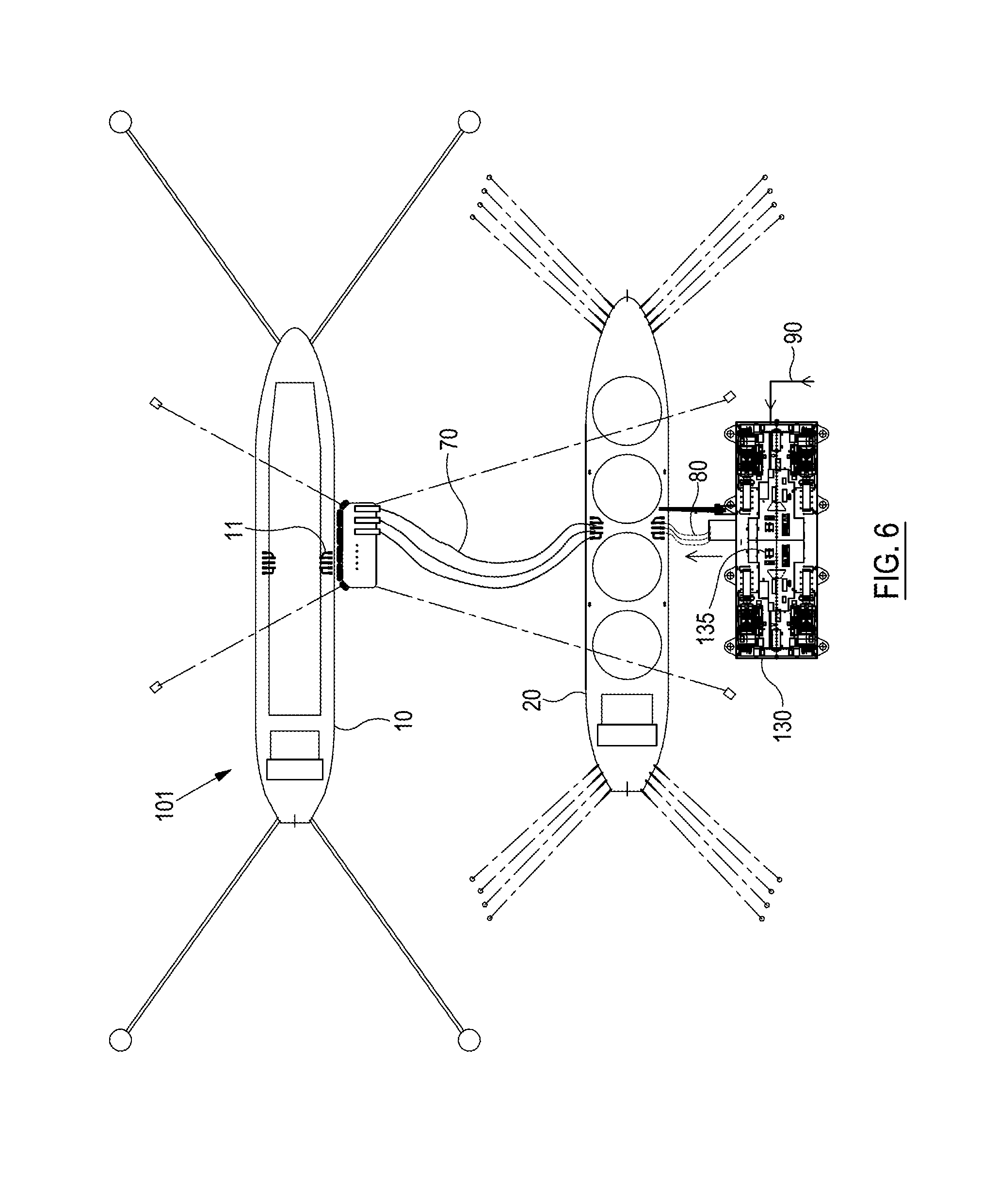
[0029] FIG. 6 is an overhead representation of a system for liquefying gas and loading the liquefied gas onto a cargo vessel;
[0030] FIG. 7 is an overview representation of the system of FIG. 1 expanded to include a power plant;
[0031] FIG. 8 is a side view of the power plant of the system of FIG. 7 when installed on seabed;
[0032] FIG. 9 is a top view of the power plant of FIG. 8;
[0033] FIG. 10 is another side view of the power plant of FIGS. 7 and 8 in larger scale;
[0034] FIG. 11 is an overhead representation of a system of FIGS. 1 and 7 expanded to include a water generation facility;
[0035] FIG. 12 is an overhead representation of a system for offloading liquefied gas and regasifying the offloaded gas at a location offshore;
[0036] FIG. 13 is a side view of the system of FIG. 12;
[0037] FIG. 14 is a side view representation of the system of FIGS. 12 and 13 with the cargo vessel absent;
[0038] FIG. 15 is an overhead representation of the system in the configuration of FIG. 14;
[0039] FIG. 16 is an overhead representation of is an overhead representation of a system for offloading liquefied gas and regasifying the offloaded gas at a location offshore;
[0040] FIG. 17 is a side-view representation of the system of FIG. 16;
[0041] FIG. 18 is a side-view representation of part of the system of FIGS. 16 and 17 in larger scale;
[0042] FIG. 19 is an overhead view of a system for offloading liquefied gas and storing the offloaded gas in a circular platform;
[0043] FIG. 20 is a close-up view of the platform of the system of FIG. 19; and
[0044] FIG. 21 is an overhead view of another system for offloading and regasifying gas from a vessel.
DETAILED DESCRIPTION
[0045] Referring to FIGS. 1 to 4 and FIGS. 5A to 5C, a system 1 is generally depicted for offloading liquefied natural gas (LNG) from a cargo vessel in the form of an LNG carrier 10 and regasifying the offloaded gas at a location offshore. The system 1 includes a floating storage unit (FSU) in the form of a storage vessel 20. The storage vessel 20 is spread-moored to the seabed by seabed moorings 24.
[0046] A jack-up platform 30 is positioned offshore in proximity to the storage vessel 20, and a regasification facility is provided on the jack-up rig for regasifying the LNG which is offloaded from the LNG carrier 10.
[0047] The jack-up platform 30 has legs 31 which are arranged to be supported on the seabed and a hull 32 which is arranged to be jacked up along the legs 31 to a position above the sea surface 3. The installation of the jack-up 30 takes place through manoeuvring the hull 32 into the indicated position with the legs 31 in raised position (FIG. 5A), lowering the legs 31 to engage the seabed 2 (FIG. 5B), and then moving the hull 32 upward along the legs to the position where the bottom of the hull is spaced well above the wave zone of the sea surface 3 (FIG. 5C).
[0048] First tubing 70 extends between the carrier 10 and the storage vessel 20 and provides fluid communication for offloading the LNG from the LNG carrier 10 to the storage vessel 20 through the first tubing.
[0049] Second tubing 80 extends between the storage vessel 20 and the regasification facility 35 of the jack-up rig 30 for transferring LNG from the storage vessel 20 to the regasification facility for regasification. The second tubing 80 is in the form of hoses which are aerial hoses (not in the water) which are suspended in U-shape in the air between the storage vessel 20 and the jack-up 30.
[0050] Third tubing 90 is provided for transporting the regasified gas from the regasification facility 35 to shore, e.g. through a seabed pipeline.
[0051] The LNG carrier 10 is moored to the seabed through seabed buoy moorings 14 (e.g. a Conventional Buoy Mooring system--CBM), a distance away from the storage vessel 20. The LNG carrier 10 visits from time to time to offload LNG to the storage vessel 10. After offloading to the storage vessel 20, the LNG carrier 10 departs, e.g. to collect a new amount of LNG from a supplier.
[0052] Typically, the storage vessel 20 has greater storage capacity for LNG than the LNG carrier 10. The storage vessel 20 remains in place on a permanent basis, and together with the jack-up platform 30 provides an offshore terminal which provides regasification.
[0053] The system 1 includes in this example a floating travel unit 60. The floating travel unit 60 is configured to travel between the storage unit 20 and the LNG carrier 10 to facilitate connection of the first tubing 70 to the mid-ships cargo manifold 11 of the LNG carrier 10. When the LNG carrier 10 has been moored, the floating travel unit 60 travels from an initial position, typically near the storage vessel 20, across the sea on a path toward and into position adjacent to a side of the LNG carrier 10. A length of the tubing 70 to be connected to LNG carrier 10 is carried by the travel unit to the LNG carrier 10. The travel unit 60 has a lifting and handling device, e.g. a crane, which comprises a boom which is used to reach over the side of the LNG carrier and lift and manoeuvre a tubular end section 70e of the first tubing 70, over the side of the LNG carrier and land the end section 70e onto a surface in front of the cargo manifold of the cargo vessel for connection thereto.
[0054] The travel unit 60 operates to move into the position adjacent to the LNG carrier 10 by a chain crawling propulsion system. Seabed anchored chains 64 are provided and the travel unit 60 has winches or devices which are selectively operable to draw in the relevant anchored chain 64 so as to propel the unit 60 across sea and into the position adjacent to the LNG carrier 10 as depicted. The travel unit 60 can be the connection unit 30 as described in published US patent application US 2017/0253302, and the chain crawling propulsion system may be that as described in published US patent application US 2017/0253302 for the connection unit described therein, and the disclosures of these are incorporated herein by reference.
[0055] The fluid cargo may in other variants be liquefied petroleum gas (LPG).
[0056] As can be appreciated, the system 1 does not require use of a jetty or any mooring to the jetty of any of: the storage vessel 20; the regasification facility 35 and/or platform 30; and the LNG carrier 10. Nor are any of these moored to each other in the system 1. The moorings are to the seabed only. The system 1 can advantageously allow transfer of fluid cargo offshore, far away from shore, at sea. Large separation distance is also achieved between the cargo vessel and the storage vessel (typ. 150 m or more) providing safe fluid transfer between the vessels.
[0057] The installation and removal of the jack-up platform 30 can for example be performed as in the following. When arrived at location, the platform 30 uses an onboard jacking system to lower the platform legs 31 onto the seabed 2. The jacking system operates to lift the hull 32 of the platform off the water to suitable elevation, e.g. 15-20 m above the waterline. The platform legs are locked at this position and the jacking system is removed from the platform and returned to shore. The jacking system can thus be standardized and leased to each project to save cost as well as maintenance. Removal of the jack-up platform can be performed in the reverse order to the installation, e.g. when a project is finished and/or to relocate the jack-up platform. To do so, the jacking system is brought out to the platform 30 and the hull 32 is jacked down until it floats. The legs 31 are pulled up and the platform 30 can simply be towed to the new location by a standard tug boat or use of a submersible barge.
[0058] Referring to FIG. 6, instead of the regasification facility 35 on the jack-up platform 30, a gas liquefaction facility 135 is provided on jack-up 130. The system 101 in FIG. 6 is therefore arranged for liquefying gas supplied to the liquefaction facility 135 through third tubing 90. The liquefied gas, e.g. LNG, is transferred through second tubing 80 onto the long-term storage facility 20, then transferred through first tubing 70 and loaded onto a visiting cargo vessel 10 through the cargo manifold 11. Alternatively, the gas for liquefaction is delivered to the facility 135 by other means.
[0059] In FIGS. 7 to 10, the system 1 is expanded to include a power plant 235 on a separate jack-up platform 230 which includes a hull 232 and legs 231. The jack-up platform 230 can be installed in the same manner as the jack-up platform 30. Some of the regasified gas from the regasification facility 35 is supplied to the power plant 235 to produce electrical power. The electrical power is supplied to shore or other receiver through power cable 297. Some of the regasified gas is also supplied to shore through third tubing 90, e.g. through subsea pipeline. The regassification facility may also be located on the same jack-up platform as the power plant.
[0060] In FIG. 11, the system 1 is expanded further to include a water generation facility 335 on a separate jack-up platform 330. Power from the power plant 235 is used to operate the facility 235 which converts seawater to freshwater. The freshwater may be supplied to shore through water pipe 397. The water generation facility may also be located on the same jack-up platform as the power plant.
[0061] Referring now to FIGS. 12 to 14, the LNG carrier 10 is instead moored side-by-side to the storage vessel 20. The system 401 of FIGS. 12 to 14, therefore does not have the travel unit 60 of the above described system 1. The first tubing is in the form of hosing 470 for offloading LNG from the LNG carrier 10 to the storage vessel 20. The storage vessel 20 is moored to the seabed 2, and the LNG carrier 10 is moored to the storage vessel 20. LNG is transferred from the storage vessel 20 through hosing 80 and regasified on the regas facility 35 of the jack-up platform 30. When offloaded, the LNG carrier 10 departs, leaving the storage vessel 20 and the regas platform 30 in place (see FIGS. 14 and 15), where it may continue to process and regasify the LNG from the tanks of the storage vessel 20 and supply the regasified gas to shore through third tubing 90.
[0062] In such a case, to allow the LNG carrier to be positioned alongside the storage vessel 20, the mooring lines 426 from the storage vessel 20 are connected slightly below the keel of the FSU 20. Additional water depth may typically then be required to accommodate this mooring configuration. Hence, the solution may be best suitable for areas where sufficient water depth while preferably close enough to shore to avoid installation of a long high-pressure gas pipeline.
[0063] The described side-by side mooring configuration may also be used in combination with a power plant, water generation facility or gas liquefaction facility described previously.
[0064] Turning now to FIGS. 16 to 18, a seabed tower 530 is used in place of the jack-up platform 30 with the regasification plant. The seabed tower has a manifold 534 into which end portion 80e of the second tubing 80 is connected. The manifold 534 is positioned on a platform 532 above the sea surface. The platform 532 is supported on the seabed 2 on at least one leg 530 which extends upward from the seabed penetrating through the sea surface 3. A conduit connects the manifold fluidly with a seabed pipeline 90. The system 501 is therefore provided such that the LNG is offloaded and transferred to the storage vessel (FSU) 20 in the same way as in the system 1. However, the LNG in this example is transported from the storage vessel 20, into the manifold 534 on the tower 530, through the conduit 536 and into the pipeline 90 through which it travels in liquefied form at high pressure to shore or to a downstream facility for regasification. An insulated LNG Pipe In Pipe (PIP) 90 is then typically used from the FSU to the onshore facilities. To limit cost and potential temperature effects, the storage vessel 20 (FSU) may typically be located in very shallow water for obtaining a preferably shortest possible LNG pipeline to shore.
[0065] Alternatively, the storage vessel 20 can include a regasification facility, i.e. forms an FSRU, such that regasified LNG is conveyed from the storage unit 20 to the tower 530 and into the pipeline 90 to shore. The tower platform 530 e.g. a "tripod tower" can make it feasible to moor a FSRU in shallower water and yet still enable a safe and robust transfer of high-pressure gas from the FSRU to the onshore gas pipeline 90.
[0066] The seabed tower 530 may also be used in combination with the side-by-side mooring configuration described previously instead of the travel unit 60 shown in FIG. 16.
[0067] Referring to FIGS. 19 and 20, a regasification unit 630 is provided in the form of a platform having a circular section moored to the seabed. LNG is offloaded from the LNG carrier 10 through tubing 70 to the unit 620 and regasified gas is transferred through tubing 90 to shore. Optionally, the regasification unit 630 includes a power production facility and/or fresh water production facility, or alternatively either of these can be provided on separate platforms. The unit provides storage for offloaded LNG and a regasification facility 635 for regasifying the LNG from tanks on the unit. This can be suitable for small scale LNG operations where the amount or frequency of LNG received is limited so as to be within the storage capacities and processing rates. A travel unit 60 may be used to connect the tubing 70 to the unit 630. The unit 630 is circular in section which provides highly favourable motion characteristics when exposed to waves.
[0068] The unit 630 may have Bi-lobe-Shaped IMO Type C LNG tanks 613 for storing the offloaded LNG. These tanks 613 are arranged as 60 degree "cake slices" around the circumference of the unit 630 and may be an attractive solution for efficient and maximizing storage. In other implementations however, other LNG containment systems or tanks may alternatively be used.
[0069] In FIG. 21, a jack-up platform 730 is provided with a regasification facility 735. The system 701 does not require use of the travel unit 60 or floating storage vessel 20. In use, a first articulated tug and barge 710 arrives and is moored to the Seabed Buoy Mooring System. A floating LNG hose is reeled out form the platform 730 and connected to a specially designed hose connector at the barge 710. LNG is pumped from the first barge 710 to the platform 730 and the regasification operation starts using the regasification facility 735. The tug 723 used for the first barge 710 then leaves to pick up a second articulated tug and barge 723. The second barge 723 arrives and is moored to seabed moorings. The process of pumping the LNG from second barge 723 starts and progresses slowly when the first barge 710 is nearly empty. The pumping rate from the second barge 723 is reduced until the first barge 710 is empty. In this way, continuous LNG supply to the regasification platform 730 can be obtained without installing an FSU or onshore LNG storage. The regasified LNG is conveyed from the facility 735 to shore via a pipeline 90. The solution can be advantageous for small scale LNG terminals where it may not be economical to invest in onshore LNG storage or to install a permanently moored Floating Storage Unit (FSU).
[0070] In other variants, the offloaded gas may be used to generate power, and the power can be transmitted to shore from the platform 730 via an electrical power cable.
[0071] Two specially designed hoses reels with floating LNG hose are installed on the platform 730, and the platform 730 is further equipped with complete LNG regasification system, power generation system and other facilities required to enable a complete the facility.
[0072] The above example is given with use of two barges to be towed by tugs. However, in other variants, the same principle may also be used with any type of small-scale LNG ships. An alternative is to convert old platform Supply Vessels (PSV's) to LNG ships. Currently, there are a number or PSV's in lay-up due to reduced activity in the upstream oil & gas sector. Such PSV's may therefore be converted to small-scale LNG ships that will be attractive to use in combination with the SRP as described. A key advantage of such PSV's compared to traditional LNG ships is that the PSV's normally are equipped with Dynamically Position System (DP) and several thrusters and propellers to obtain unique manoeuvring capabilities.
[0073] With such DP system, mooring of the PSV to seabed moored buoys (e.g. CBM) can take place without tugs. During heavy weather, the DP system at the PSV may also be used to assist in positioning of the vessel in addition to the mooring lines provided by the mooring system.
[0074] Possible Advantages and Applications
[0075] The system solutions described above for jetty-less terminals may significantly reduce the overall cost for construction of new LNG receiving terminals. Furthermore, higher availability and uptime may be obtained as the FSU can be designed to stay at location on a permanent basis. Hence, the FSU (or FSRU) does not need to be disconnected and removed from the LNG terminal in case of strong wind or high waves. This can help to achieve the highest possible gas delivery regularity for new LNG receiving facilities.
[0076] Provision of the regasification, power production, and/or water production on jack-up platforms can offer flexibility, convenience of use, and suitability for adverse weather. The jack-up platform can be built at any yard and towed location by a tug boat. When arrived at location, it can simply be installed using it its leg jacking system and without use of any large installation vessels or other expensive facilities. This in effect makes the jack-up platforms "self-installing". A self-installed jack-up platform providing the regasification facility can significantly lower overall cost compared to traditional solutions. After installation, the jack-up platform will be situated well above the exposed wave zone, and will therefore avoid exposure to high wave forces, such that it may be well suited for use in areas exposed to large waves and strong wind (hurricane, cyclone and monsoon areas). The jack-up platforms may also be removed and relocated to another LNG terminal location without use of expensive installation vessels. The jack-up solution can enable a very flexible and cost-effective installation of a regasification platform 30. No special or expensive installation vessels are needed for providing the terminal. The jack-up solution can also enable offshore LNG terminals with a regasification facility to be installed at shallower water depth than typically possible with the traditional spread moored FSRU. This can allow the length of the high-pressure gas pipeline to the onshore facilities to be minimized and may increase location flexibility.
[0077] In the systems described above, an old and inexpensive LNG Carrier can be used to provide the storage vessel 20 (constituting an FSU). An advantage of using the FSU together with a separate jack-up regasification platform 30 can be that expensive LNG regasification equipment and associated facilities can be installed on a newly built jack-up platform instead of by converting an LNG carrier to an FSRU. This may make it possible to use an old LNG carrier (e.g. 25 years old) as the FSU until it has to be scrapped (e.g. after an 5-10 additional years of use). Then, this retired FSU can be replaced with another old FSU that may operate for the next 5-10 years. This can have cost and availability benefits and can increase flexibility. The mooring systems may therefore be re-used (typical lifetime 25-30 years). The required modification of the LNG storage vessel 20 (FSU) can be very moderate and extensive life extension of the FSU can be minimized.
[0078] The jack-up regasification platform solution can also help to solve another challenge that traditional spread moored FSRU techniques are facing. Since the regasification platform is fixed to the seabed, the platform will not move in waves. Hence, a fixed, static high-pressure pipeline can be used from the deck of the regasification platform and down to the seabed, rather than flexible gas risers which can be exposed to significant wave dynamics in extreme weather, (hurricane, cyclones, etc.), as used in prior art solutions of connecting an FSRU to a Pipe-Line End Manifold (PLEM) and as often can be a limiting factor as to whether an FSRU can be installed at a given location or not. In the examples of the invention, LNG transfer from the storage vessel (FSU) 20 to the regasification platform 30 can advantageously be by use of LNG hoses arranged well above the wave action zone.
[0079] The solution of providing offshore power production on a jack-up platform using regasified LNG, e.g. the platform 230, can be advantageous for the same or similar reasons as described above for regasification in relation to installation, conveyance (in this case of power) to shore, weather, and location, etc. Installing the power plant on the platform 230 offshore may avoid space/cost restrictions as may otherwise be associated with onshore installation. The produced power can be conveniently transmitted to shore by use of a high-voltage power cable.
[0080] Utilizing a jetty-less liquefaction platform 130 in combination with an old and inexpensive storage vessel 20 (FSU), may allow for stranded gas to be liquified and transported by vessel to consumers in a way that can be economical to develop. Large amounts of "stranded" natural gas can be found at offshore and onshore fields around the world far away from existing gas pipelines such that they can be considered "stranded" in location. In such cases, the only economical way to transport such gas to the consumers may be to liquefy the natural gas to LNG and transport it to the consumers by LNG ships, and the liquefaction platform 130 can facilitate such activity. The platform 130 can conveniently also be used in a near shore configuration where the gas is fed from an onshore location. The solution of the liquefaction platform 130 can otherwise be advantageous in a similar way to the regasification platform 30 in relation to installation, fluid conveyance (in this case of gas to the platform 130), weather, and location, etc. A particular advantage can be the relocation flexibility as some of the "stranded" gas fields may have a moderate amount of gas. The liquefaction platform may therefore be relocated several times between various stranded gas fields during its lifetime.
[0081] Also, the solution of water generation platform on the jack-up 330 is advantageous in a similar way to the regasification platform 30 in relation to installation, fluid conveyance (in this case of fresh water to shore), weather, and location, etc. The solution can facilitate provision of fresh water for developing countries and clean gas power for consumers.
[0082] The use of the travel unit 60 can allow ship to ship transfer of LNG for a spread moored FSU (or FSRU) via spread-mooring lines installed from the deck level of the FSU 20 where the LNG carrier is moored typical 150 m from the FSU. The LNG carrier can therefore be moored without interference with the deck mounted FSU mooring lines, but yet be connected readily to the LNG carrier 10 for transfer of LNG. The solution can cope well with high sea states and avoids problems of relative movement between the LNG carrier and the storage vessel 20 as can typically occur when moored in a side-by-side configuration with typically 5 m vessel separation. This may facilitate higher LNG transfer regularity than for example side by side mooring to the FSU.
[0083] The small-scale solution using the offshore regasification platform 730 served by tugs and barges can be advantageous for the same or similar reasons as described above for regasification e.g. by the jack-up platform 30 in relation to installation, conveyance of gas (regasified LNG) and/or power to shore, weather, and location, etc. A number of small-scale LNG receiving facilities are planned to be installed in hurricane/cyclone exposed areas like Caribbean and South-East Asia. In the event of extreme weather, the temporary storage vessel, e.g. the barge or PSV, can disconnect from the connecting tubing, and leave in due time before the hurricane/cyclone arrives at the site. The only facilities that is left in place is then the regasification platform 730 and the mooring buoys. Since the regasification platform 730 is jack-up and elevated well above the maximum wave height, the platform can be very well suited for such locations.
[0084] At many locations, the primary need may be electric power. Such need may be particularly apparent for countries with island communities e.g. where there are thousands of small islands such as Indonesia, Philippines, or the Caribbean. A small offshore LNG to Power solution may therefore be perfectly suited for these locations. The solutions of the regassification platform 730 in combination with a temporary storage vessel e.g. barge or PSV, may also be expanded to include offshore power generation on the same platform 730 as the regas equipment is installed. In such case, no gas pipeline will be needed between the platform and shore. Instead, a high-voltage power cable may be used to transmit power to shore with minimum of power loss.
[0085] The solution of transfer using the platform tower 530 can be useful where onshore regasification may be preferred. It can nonetheless benefit from use of an old FSU located offshore as the LNG storage.
[0086] The solution uses areal LNG hoses and the connection between the LNG hoses and the pipe in pipe (PIP) pipeline via the inside column 31 can thus be protected from any wave forces (more safe and robust solution). The tower provides an effective fixed connection on the seabed to the pipe in pipe pipeline 90 and overcomes challenges in risks of exposure in prior art submerged LNG hoses in the event of waves and extreme events such as e.g. a 100-year wave as well as Tsunami condition.
[0087] Small scale LNG business may be facilitated by the solution of the "circular" regasification unit 630 for import of smaller quantities of LNG (say 20,000-30,000 m.sup.3) by use of smaller LNG ships.
[0088] In areas mentioned above typically are exposed to hurricanes, cyclones and monsoons, the solution can provide robust LNG receiving terminal. Motion characteristics of such a circular unit can be verified to be very favorable when exposed to large waves compared to for instance a barge-shaped or ship-shaped hull. Bi-lobe tanks can have a well proven performance in an LNG containment system.
* * * * *
D00000
D00001
D00002
D00003
D00004
D00005
D00006
D00007
D00008
D00009
D00010
D00011
D00012

D00013

D00014

D00015

D00016

D00017

D00018

D00019

XML
uspto.report is an independent third-party trademark research tool that is not affiliated, endorsed, or sponsored by the United States Patent and Trademark Office (USPTO) or any other governmental organization. The information provided by uspto.report is based on publicly available data at the time of writing and is intended for informational purposes only.
While we strive to provide accurate and up-to-date information, we do not guarantee the accuracy, completeness, reliability, or suitability of the information displayed on this site. The use of this site is at your own risk. Any reliance you place on such information is therefore strictly at your own risk.
All official trademark data, including owner information, should be verified by visiting the official USPTO website at www.uspto.gov. This site is not intended to replace professional legal advice and should not be used as a substitute for consulting with a legal professional who is knowledgeable about trademark law.