Hot Stamped Steel
SENGOKU; Akihiro ; et al.
U.S. patent application number 16/097771 was filed with the patent office on 2019-05-30 for hot stamped steel. This patent application is currently assigned to Nippon Steel & Sumitomo Metal Corporation. The applicant listed for this patent is NIPPON STEEL & SUMITOMO METAL CORPORATION. Invention is credited to Koji AKIOKA, Akihiro SENGOKU, Hiroshi TAKEBAYASHI.
| Application Number | 20190160507 16/097771 |
| Document ID | / |
| Family ID | 60266417 |
| Filed Date | 2019-05-30 |

| United States Patent Application | 20190160507 |
| Kind Code | A1 |
| SENGOKU; Akihiro ; et al. | May 30, 2019 |
HOT STAMPED STEEL
Abstract
A hot stamped steel according to one embodiment of the present invention includes a base material and a plated layer, wherein the plated layer includes an interface layer, an intermediate layer, and an oxide layer in order from a base material side to a surface side; in which compositions and thicknesses of each layer are controlled.
| Inventors: | SENGOKU; Akihiro; (Tokyo, JP) ; TAKEBAYASHI; Hiroshi; (Tokyo, JP) ; AKIOKA; Koji; (Tokyo, JP) | ||||||||||
| Applicant: |
|
||||||||||
|---|---|---|---|---|---|---|---|---|---|---|---|
| Assignee: | Nippon Steel & Sumitomo Metal
Corporation Tokyo JP |
||||||||||
| Family ID: | 60266417 | ||||||||||
| Appl. No.: | 16/097771 | ||||||||||
| Filed: | May 10, 2016 | ||||||||||
| PCT Filed: | May 10, 2016 | ||||||||||
| PCT NO: | PCT/JP2016/063856 | ||||||||||
| 371 Date: | October 30, 2018 |
| Current U.S. Class: | 1/1 |
| Current CPC Class: | C23C 2/12 20130101; C23C 28/322 20130101; C23C 28/321 20130101; C23C 28/345 20130101; C22C 38/06 20130101; B21D 22/022 20130101; C21D 8/005 20130101; C22C 38/28 20130101; C22C 38/001 20130101; C22C 38/00 20130101; C22C 38/02 20130101; C22C 38/58 20130101; C21D 6/008 20130101; C22C 38/32 20130101; C23C 2/06 20130101; C22C 38/002 20130101; C22C 18/04 20130101; C21D 6/002 20130101; C21D 6/005 20130101; C23C 2/28 20130101; C22C 38/04 20130101 |
| International Class: | B21D 22/02 20060101 B21D022/02; C22C 18/04 20060101 C22C018/04; C22C 38/32 20060101 C22C038/32; C22C 38/28 20060101 C22C038/28; C22C 38/06 20060101 C22C038/06; C22C 38/04 20060101 C22C038/04; C22C 38/02 20060101 C22C038/02; C22C 38/00 20060101 C22C038/00; C21D 8/00 20060101 C21D008/00; C21D 6/00 20060101 C21D006/00 |
Claims
1. A hot stamped steel comprising: a base material; and a plated layer, wherein the plated layer includes an interface layer, an intermediate layer, and an oxide layer in order from a base material side to a surface side, in the interface layer, a structure includes 99 area % or more in total of .alpha.Fe, Fe.sub.3Al, and FeAl, an average Al content is in a range of 8.0 mass % or more and 32.5 mass % or less, an average Zn content is limited to more than a Zn content of the base material and 5 mass % or less, a remainder of a chemical composition includes Fe and impurities, and an average layer thickness is 1.0 .mu.m or more, in the intermediate layer, a structure includes 99 area % or more in total of Fe(Al, Zn).sub.2 and Fe.sub.2(Al, Zn).sub.5, an average Al content is 30 mass % to 50 mass %, an average Zn content is 10 mass % to 40 mass %, a remainder of a chemical composition includes Fe and the impurities, and an average layer thickness is 5.0 .mu.m or more, and in the oxide layer, an average layer thickness is 0.1 .mu.m to 3.0 .mu.m.
2. The hot stamped steel according to claim 1, wherein the average layer thickness is 1.0 .mu.m to 10.0 .mu.m in the interface layer.
3. The hot stamped steel according to claim 1, wherein a total weight per unit area of Al and Zn in the plated layer is 20 g/m.sup.2 or more and 100 g/m.sup.2 or less.
4. The hot stamped steel according to claim 1, wherein the plated layer further includes more than 0 mass % and 10.0 mass % or less of Si on average, and in the intermediate layer, 0 area % to 50 area % of the Fe(Al, Zn).sub.2 and the Fe.sub.2(Al, Zn).sub.5 are substituted into Fe(Al, Si).
5. The hot stamped steel according to claim 2, wherein a total weight per unit area of Al and Zn in the plated layer is 20 g/m.sup.2 or more and 100 g/m.sup.2 or less.
6. The hot stamped steel according to claim 2, wherein the plated layer further includes more than 0 mass % and 10.0 mass % or less of Si on average, and in the intermediate layer, 0 area % to 50 area % of the Fe(Al, Zn).sub.2 and the Fe.sub.2(Al, Zn).sub.5 are substituted into Fe(Al, Si).
7. The hot stamped steel according to claim 3, wherein the plated layer further includes more than 0 mass % and 10.0 mass % or less of Si on average, and in the intermediate layer, 0 area % to 50 area % of the Fe(Al, Zn).sub.2 and the Fe.sub.2(Al, Zn).sub.5 are substituted into Fe(Al, Si).
8. The hot stamped steel according to claim 5, wherein the plated layer further includes more than 0 mass % and 10.0 mass % or less of Si on average, and in the intermediate layer, 0 area % to 50 area % of the Fe(Al, Zn).sub.2 and the Fe.sub.2(Al, Zn).sub.5 are substituted into Fe(Al, Si).
Description
TECHNICAL FIELD OF THE INVENTION
[0001] The present invention relates to a hot stamped steel.
RELATED ART
[0002] There are cases in which structural members (compacts) that are used for cars and the like are manufactured by hot stamping (hot pressing) in order to increase both the strength and the dimensional accuracy. In the manufacturing of a compact by hot stamping, steel for hot stamping is heated to the Ac.sub.3 temperature or higher, and the steel for hot stamping is rapidly cooled in a die while being pressed. That is, in the manufacturing, pressing and quenching are carried out at the same time. Hot stamping enables the manufacturing of compacts having a high dimensional accuracy and a high strength.
[0003] Meanwhile, a compact manufactured by hot stamping has been worked at a high temperature, and thus iron scales are formed on the surface. Therefore, a technique in which a plated steel sheet is used as a steel sheet for hot stamping, thereby suppressing the formation of iron scales and, furthermore, improving the corrosion resistance of compacts has been proposed (refer to Patent Documents 1 to 3). For example, Patent Document 1 discloses a plated steel sheet for hot pressing on which a Zn-plated layer is formed, and Patent Document 2 discloses a plated steel sheet for a car member on which an Al-plated layer is formed. Furthermore, Patent Document 3 discloses a galvanized steel sheet for hot pressing in which a variety of elements such as Mn are added to a plated layer of the Zn-plated steel sheet. However, these plated steel sheets have problems described below.
[0004] In the technique of Patent Document 1, Zn remains on the surface of the compact after hot stamping, and thus a strong sacrificial anticorrosion action can be expected. However, in the technique of Patent Document 1, a plated steel sheet is hot-pressed in a state in which Zn is molten, and thus there is a concern that molten Zn may intrude into a base material of the plated steel sheet during hot pressing, and cracks may be generated inside the base material. These cracks are referred to as liquid metal embrittlement (hereinafter, in some cases, referred to as "LME"). Due to LME, the fatigue properties of compacts deteriorate.
[0005] Meanwhile, currently, in order to avoid the generation of LME, it is necessary to appropriately control the heating conditions during the working of a plated steel sheet. Specifically, a method or the like in which the plated steel sheet is heated until all of the molten Zn diffuses into the base material of the plated steel sheet and forms a Fe--Zn solid solution is employed. However, in order to carry out these methods, the plated steel sheet needs to be heated for a long period of time, and consequently, there is a problem of the degradation of the productivity.
[0006] In the technique of Patent Document 2, Al having a high melting point than Zn is used as a component of the plated layer, and thus the concern of the intrusion of molten metal into a base material of a plated steel as in Patent Document 1 is small. Therefore, according to the technique of Patent Document 2, excellent LME resistance can be obtained, and furthermore, it is expected that a compact having excellent fatigue properties can be obtained after hot stamping. However, for compacts on which an Al-plated layer is formed, there is a problem in that it is difficult to form a phosphate film during a phosphating treatment that is carried out before the painting of a member for a car. In other words, the compact by the technique of Patent Document 2 has a problem in that the phosphatability cannot be sufficiently obtained.
[0007] In the technique of Patent Document 3, the outermost layer (oxidized film) of a hot stamped steel is reformed, thereby improving weldability. However, in the technique of Patent Document 3, there is also a concern that LME may be generated and the fatigue properties of a hot stamped steel may not be sufficiently obtained. In addition, in the technique of Patent Document 3, there is another concern that an element that is added to a plated layer may degrade the phosphatability.
PRIOR ART DOCUMENT
Patent Document
[0008] [Patent Document 1] Japanese Unexamined Patent Application, First Publication No. 2003-73774
[0009] [Patent Document 2] Japanese Unexamined Patent Application, First Publication No. 2003-49256
[0010] [Patent Document 3] Japanese Unexamined Patent Application, First Publication No. 2005-113233
DISCLOSURE OF THE INVENTION
Problems to be Solved by the Invention
[0011] The present invention has been made in consideration of the above-described circumstances, and an object of the present invention is to provide a hot stamped steel being excellent in terms of fatigue properties, a phosphatability, coating adhesion, and weldability.
Means for Solving the Problem
[0012] The gist of the present invention is as described below.
[0013] (1) According to an aspect of the present invention, there is provided a hot stamped steel including a base material and a plated layer, in which the plated layer includes an interface layer, an intermediate layer, and an oxide layer in order from a base material side to a surface side; in the interface layer, a structure includes 99 area % or more in total of .alpha.Fe, Fe.sub.3Al, and FeAl, an average Al content is in a range of 8.0 mass % or more and 32.5 mass % or less, an average Zn content is limited to more than an Zn content of the base material and 5 mass % or less, a remainder of a chemical composition includes Fe and impurities, and an average layer thickness is 1.0 .mu.m or more; in the intermediate layer, a structure includes 99 area % or more in total of Fe(Al, Zn).sub.2 and Fe.sub.2(Al, Zn).sub.5, an average Al content is 30 mass % to 50 mass %, an average Zn content is 10 mass % to 40 mass %, a remainder of a chemical composition includes Fe and the impurities, and an average layer thickness is 5.0 .mu.m or more; and in the oxide layer, an average layer thickness is 0.1 .mu.m to 3.0 .mu.m.
[0014] (2) In the hot stamped steel according to (1), the average layer thickness may be 1.0 .mu.m to 10.0 .mu.m in the interface layer.
[0015] (3) In the hot stamped steel according to (1) or (2), a total weight per unit area of Al and Zn in the plated layer may be 20 g/m.sup.2 or more and 100 g/m.sup.2 or less.
[0016] (4) In the hot stamped steel according to any one of (1) to (3), the plated layer may further include more than 0 mass % and 10.0 mass % or less of Si on average, and, in the intermediate layer, 0 area % to 50 area % of the Fe(Al, Zn).sub.2 and the Fe.sub.2(Al, Zn).sub.5 may be substituted into Fe(Al, Si).
Effects of the Invention
[0017] In the hot stamped steel according to the present invention, improvements were made respectively to the alloy form of the plated layer, the Al content and the Zn content in specific layers of the plated layer, and the layer thickness of an oxide formed as the outermost layer of the plated layer. As a result, according to the hot stamped steel according to the present invention, it is possible to achieve all of the improvement in the fatigue properties of the compact based on the suppression for generating of LME, the improvement in the phosphatability of the compact and the consequent improvement in the coating adhesion, and the improvement in the weldability of the compact.
BRIEF DESCRIPTION OF THE DRAWINGS
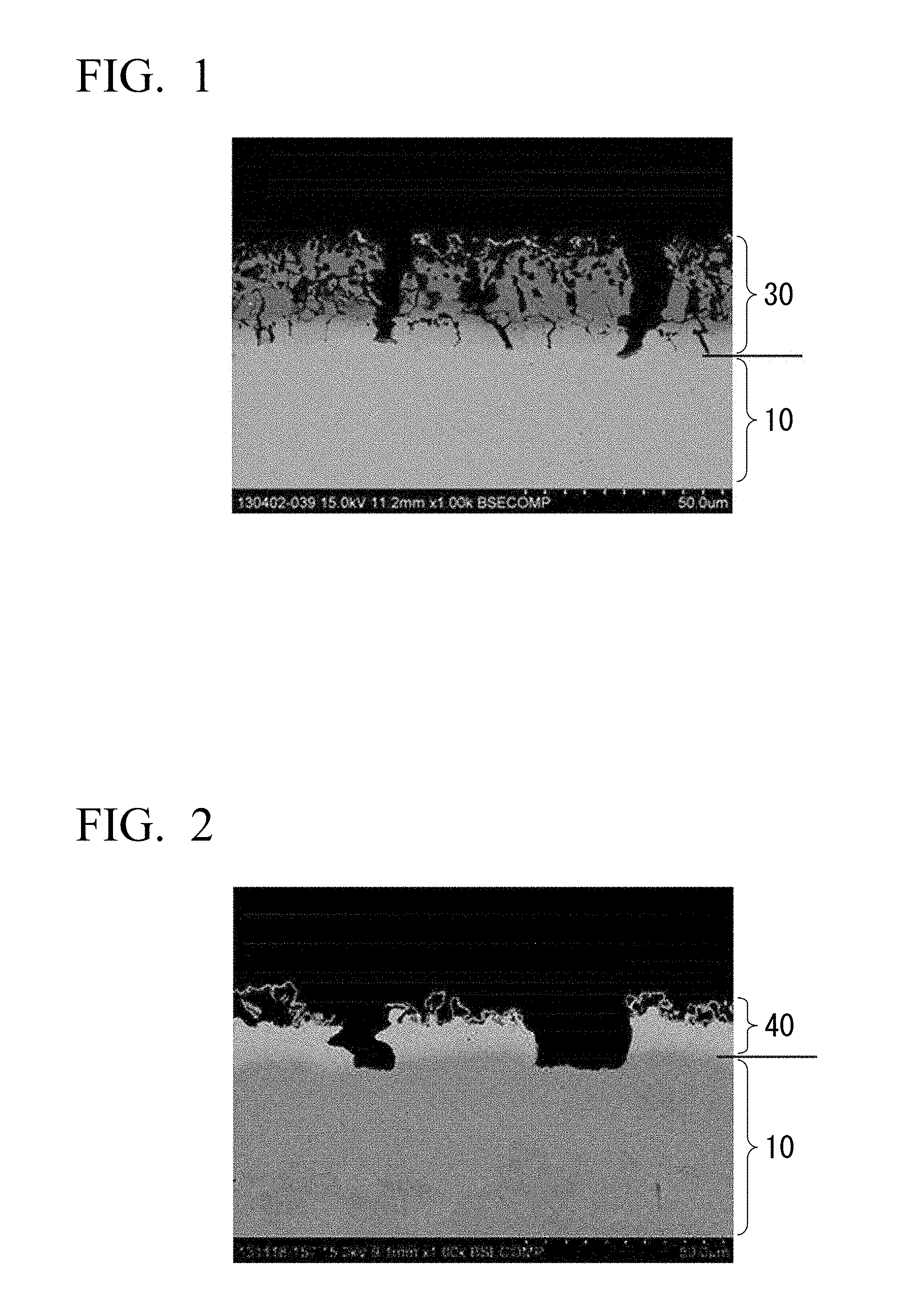
[0018] FIG. 1 is an example of a cross-sectional SEM image showing a worked portion of a compact obtained by immediately performing hot-V-bent on an Al-Zn-based plated steel after heating under the conditions of Example 1.
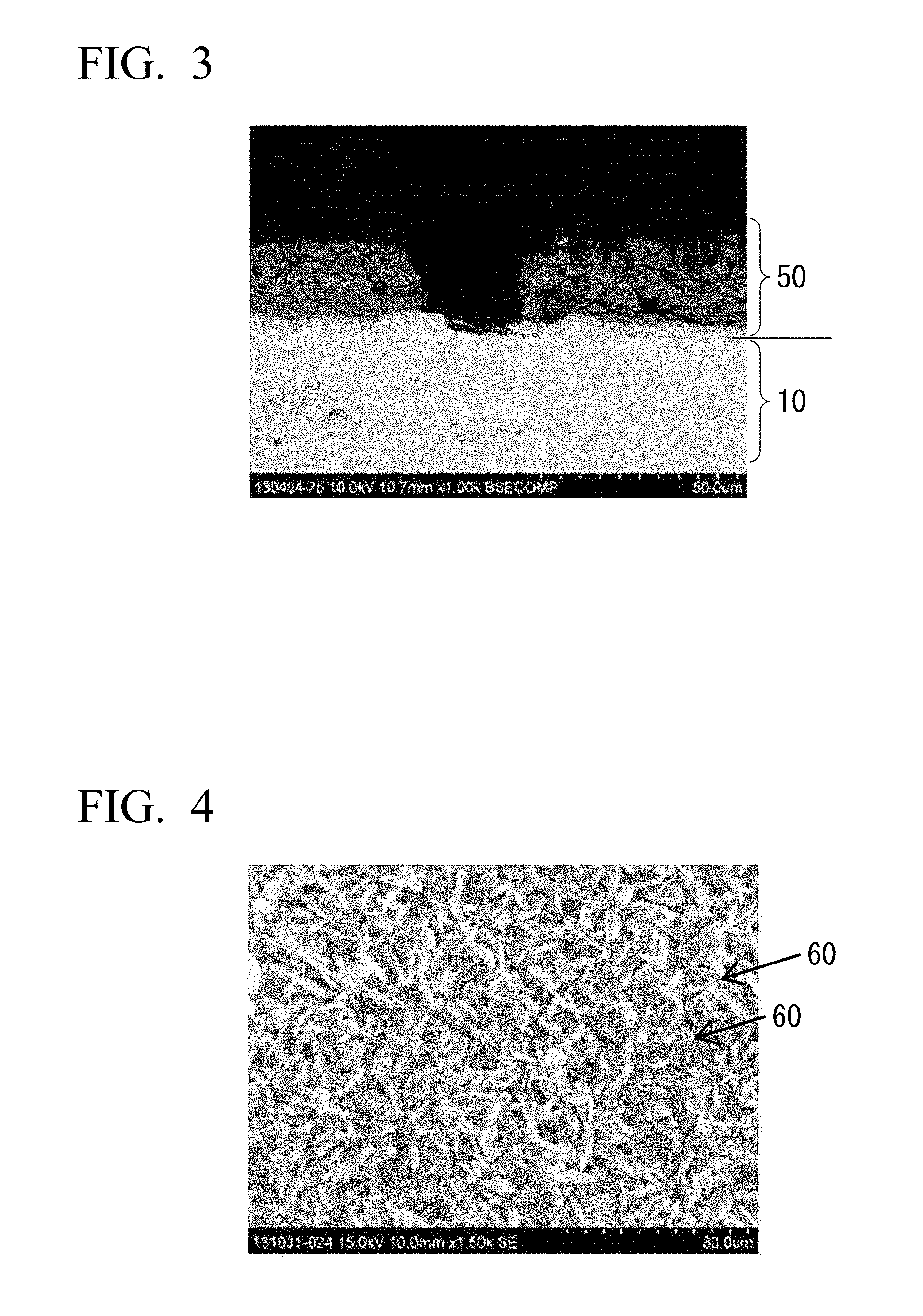
[0019] FIG. 2 is an example of a cross-sectional SEM image showing a worked portion of a compact obtained by immediately performing hot-V-bent on a Zn-based plated steel after heating under the conditions of Example 1.
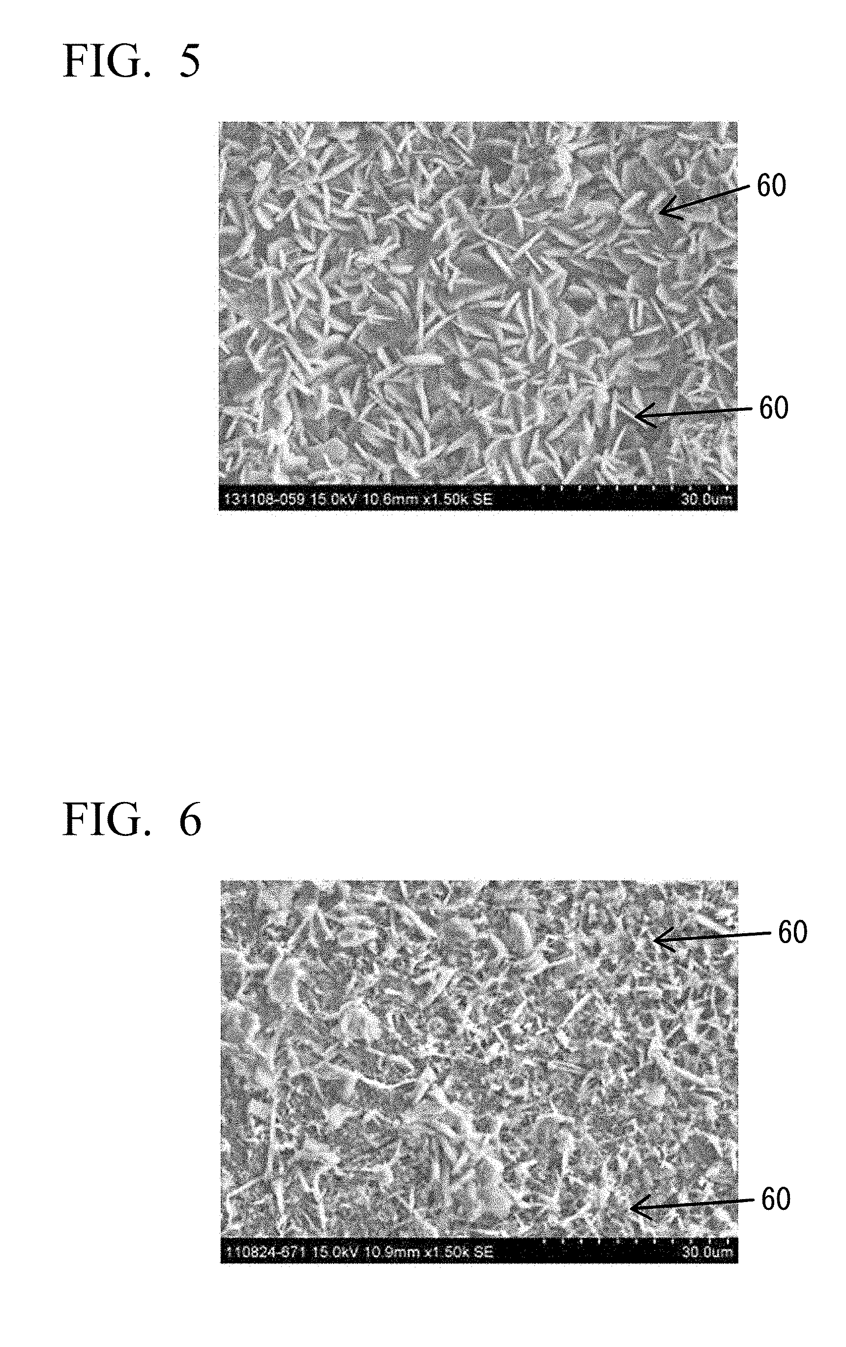
[0020] FIG. 3 is an example of a cross-sectional SEM image showing a worked portion of a compact obtained by immediately performing hot-V-bent on an Al-based plated steel after heating under the conditions of Example 1.
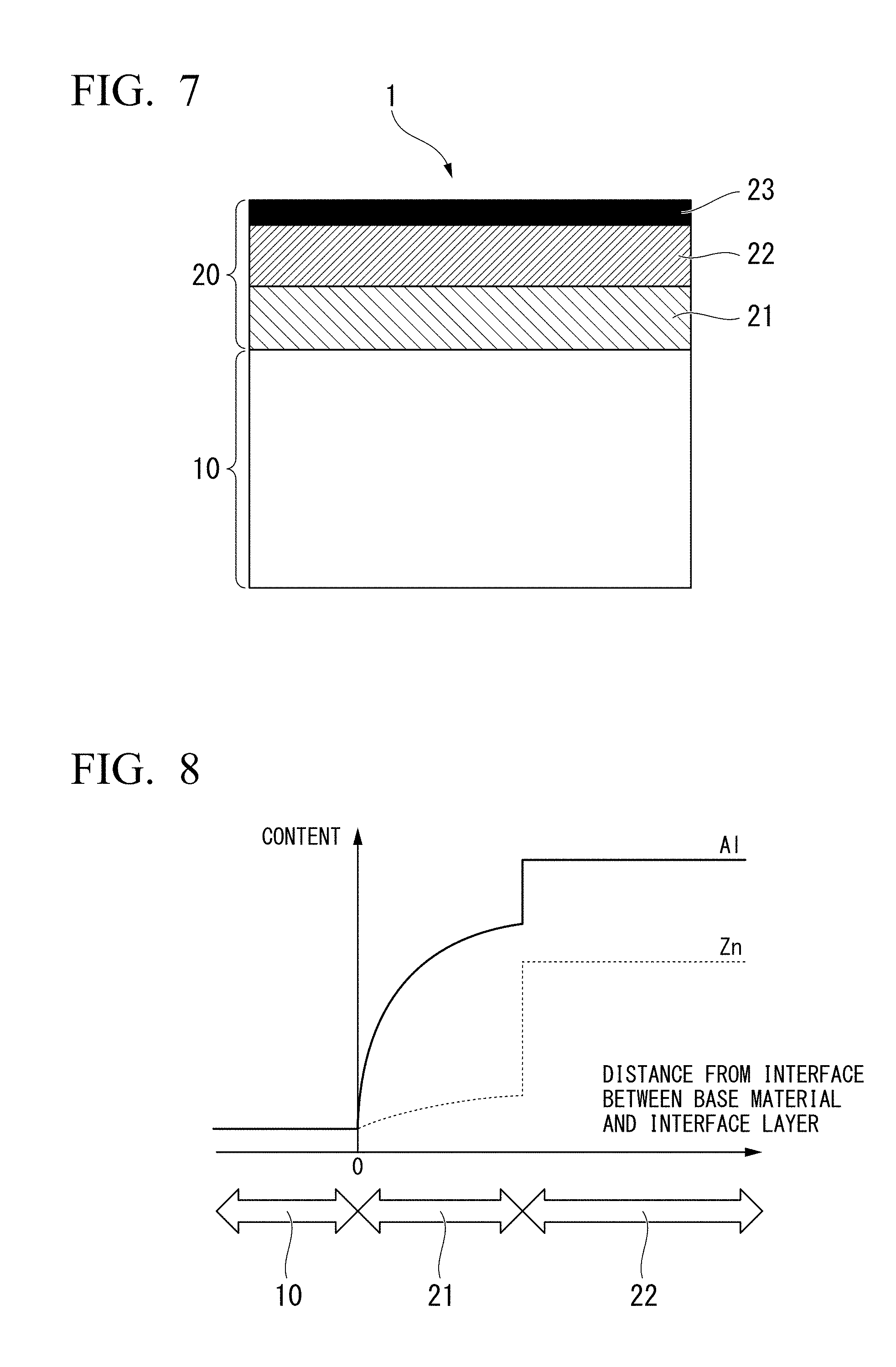
[0021] FIG. 4 is an example of a SEM image (secondary electron image) showing a surface of a compact in a case in which an Al-Zn-based plated steel is heated under the conditions of Example 1, immediately worked and rapidly cooled in a flat sheet die including a water-cooling jacket, and then subjected to a phosphating treatment.
[0022] FIG. 5 is an example of a SEM image (secondary electron image) showing a surface of a compact in a case in which a Zn-based plated steel is heated under the conditions of Example 1, immediately worked and rapidly cooled in the flat sheet die including the water-cooling jacket, and then subjected to a phosphating treatment.
[0023] FIG. 6 is an example of a SEM image (secondary electron image) showing a surface of a compact in a case in which an Al-based plated steel is heated under the conditions of Example 1, immediately worked and rapidly cooled in the flat sheet die including the water-cooling jacket, and then subjected to a phosphating treatment.
[0024] FIG. 7 is a cross-sectional view of a vicinity of a surface of a hot stamped steel according to the present embodiment.
[0025] FIG. 8 is a schematic view of an Al concentration and a Zn concentration in the vicinity of the surface of the hot stamped steel according to the present embodiment.
EMBODIMENTS OF THE INVENTION
[0026] Hereinafter, an embodiment of a hot stamped steel according to the present invention will be described in detail. Meanwhile, the unit "%" regarding the chemical composition of a hot stamped steel according to the present embodiment refers to "mass %" unless particularly otherwise described. In addition, in the present embodiment, the hot stamped steel refers to a compact obtained by carrying out hot stamping (hot pressing) on a plated steel for hot stamping. Hereinafter, there will be cases in which the hot stamped steel is simply referred to as the "compact" and the plated steel for hot stamping is simply referred to as the "steel" or the "plated steel".
[0027] The present inventors studied the fatigue properties (LME resistance) and the phosphating treatment properties of hot stamped steels (an Al-Zn-based plated steel, a Zn-based plated steel, and an Al-based plated steel). As a result, the present inventors found that, in a case in which a plated layer of a hot stamped steel includes an interface layer, an intermediate layer, and an oxide layer in order from a base material side to a surface side, a structure of the interface layer includes 99 area % or more in total of .alpha.Fe, Fe.sub.3Al, and FeAl, an Al content is in a range of 8.0 mass % or more and 32.5 mass % or less and decreases toward the base material, an average Zn content is limited to 5 mass % or less, a remainder of a chemical composition of the interface layer includes Fe and impurities, and an average layer thickness is 1.0 .mu.m or more, a structure of the intermediate layer includes 99 area % or more in total of Fe(Al, Zn).sub.2 and Fe.sub.2(Al, Zn).sub.5, an average Al content is 30 mass % to 50 mass %, an average Zn content is 10 mass % to 40 mass %, a remainder of a chemical composition of the intermediate layer includes Fe and the impurities, and an average layer thickness is 5.0 .mu.m or more, and an average layer thickness of the oxide layer is 0.1 .mu.m or more and 3.0 .mu.m or less, both the fatigue properties and the phosphatability of the hot stamped steel are favorable. Meanwhile, in the present specification, the average layer thickness refers to the average value of the maximum thickness and the minimum thickness of a subject layer (film).
[0028] <Hot Stamped Steel>
[0029] Hereinafter, the hot stamped steel according to the present embodiment will be described. A hot stamped steel 1 according to the present embodiment includes a base material 10 and a plated layer 20 as shown in FIG. 7.
[0030] [Composition of Base Material]
[0031] Hereinafter, a preferred composition of the base material in the hot stamped steel according to the present embodiment will be described. The improvement of the LME resistance and the phosphatability, which is the object of the hot stamped steel according to the present embodiment, is realized using the configuration of the plated layer. Therefore, the base material in the hot stamped steel according to the present embodiment is not particularly limited. However, in a case in which the composition of the base material is in a range described below, a compact having preferred mechanical properties in addition to the LME resistance and the phosphatability can be obtained. Hereinafter, the unit "%" of the amounts of alloying elements included in the base material refers to "mass %".
[0032] (C: Preferably 0.05% to 0.40%)
[0033] In a case in which 0.05% or more of carbon (C) is included in the base material, the strength of the hot stamped steel can be increased. On the other hand, in a case in which the C content in the base material is more than 0.40%, there are cases in which the toughness of the base material in the compact lacks. Therefore, the C content in the base material may be set to 0.05% to 0.40%. A more preferred lower limit value of the C content in the base material is 0.10%, and a still more preferred lower limit value is 0.13%. A more preferred upper limit value of the C content in the base material is 0.35%.
[0034] (Si: Preferably 0.5% or Less)
[0035] Silicon (Si) has an effect of deoxidizing steel. However, when the Si content is increased, the wettability of steel to platings is degraded, and there is a likelihood of an ordinary plating treatment being impossible. Therefore, the Si content in the base material may be set to 0.5% or less. A more preferred upper limit value of the Si content in the base material is 0.3%, and a still more preferred upper limit value of the Si content in the base material is 0.2%. A more preferred lower limit value of the Si content in the base material can be determined depending on a required deoxidation level and is, for example, 0.05%.
[0036] (Mn: Preferably 0.5% to 2.5%)
[0037] In a case in which more than 0.5% of manganese (Mn) is included in the base material, the hardenability of the base material of steel before hot stamping is enhanced, and the strength of the base material in the compact after hot stamping is increased. On the other hand, in a case in which the Mn content in the base material exceeds 2.5%, this effect is saturated. Therefore, the Mn content in the base material may be set to 0.5% to 2.5%. A more preferred lower limit value of the Mn content in the base material is 0.6%, and a still more preferred lower limit value is 0.7%. A more preferred upper limit value of the Mn content in the base material is 2.4%, and a still more preferred lower limit value is 2.3%.
[0038] (P: Preferably 0.03% or Less)
[0039] Phosphorus (P) is an impurity that is included in steel. P included in the base material, in some cases, is segregated at crystal grain boundaries in the base material and thus degrades the toughness of the base material in the compact and degrades the delayed fracture resistance of the base material. Therefore, the P content in the base material may be set to 0.03% or less. The P content in the base material is preferably as small as possible.
[0040] (S: Preferably 0.01% or Less)
[0041] Sulfur (S) is an impurity that is included in steel. S included in the base material, in some cases, forms a sulfide and thus degrades the toughness of the base material in the compact and degrades the delayed fracture resistance of the base material. Therefore, the S content in the base material may be set to 0.01% or less. The S content in the base material is preferably as small as possible.
[0042] (sol. Al: Preferably 0.10% or Less)
[0043] In a case in which a term "Al content" is used regarding the base material in the compact according to the present embodiment, this term refers to the amount of sol. Al (acid-soluble Al) in the base material. Aluminum (Al) is generally used for the purpose of deoxidizing steel. However, in a case in which the Al content is large, the Ac.sub.3 temperature of steel before hot stamping is increased, and a heating temperature necessary for the quenching of steel during hot stamping is increased, which is not desirable in terms of manufacturing by hot stamping. Therefore, the Al content in the base material may be set to 0.10% or less. A more preferred upper limit value of the Al content in the base material is 0.05%. A more preferred lower limit value of the Al content in the base material is 0.01%.
[0044] (N: Preferably 0.01% or Less)
[0045] Nitrogen (N) is an impurity that is included in steel. N included in the base material, in some cases, forms a nitride and thus degrades the toughness of the base material in the compact. Furthermore, in a case in which B is included in the base material in order to improve the hardenability of steel before hot stamping, N included in the base material, in some cases, bonds to B and thus decreases the amount of a solid solution B and degrades a hardenability-improving effect of B. Therefore, the N content in the base material may be set to 0.01% or less. The N content in the base material is preferably as small as possible.
[0046] The base material in the hot stamped steel of the present embodiment may further include one or more selected from the group consisting of B and Ti.
[0047] (B: Preferably 0% to 0.0050%)
[0048] B has an action of enhancing the hardenability of steel and is thus capable of increasing the strength of the base material in the compact after hot stamping. However, when the B content in the base material is excessive, this effect is saturated. Therefore, the B content in the base material may be set to 0% to 0.0050%. A more preferred lower limit value of the B content in the base material is 0.0001%.
[0049] (Ti: Preferably 0% to 0.10%)
[0050] Ti included in the base material bonds to N included in the base material and thus forms a nitride. In a case in which Ti and N bond to each other as described above, the bonding between B in the base material and N in the base material is suppressed, and thus the degradation of the hardenability of the base material by the formation of BN can be suppressed. Furthermore, Ti included in the base material decreases the austenite grain sizes during heating in hot stamping due to austenite pinning effect and thus also has an effect of enhancing the toughness and the like of the compact. However, when the Ti content in the base material is excessive, the above-described effect is saturated, and furthermore, there is a concern that a Ti nitride may be excessively precipitated and thus the toughness of the base material in the compact may degrade. Therefore, the Ti content in the base material may be set to 0% to 0.10%. A preferred lower limit value of the Ti content in the base material is 0.01%.
[0051] The base material configuring the hot stamped steel of the present embodiment may further include one or more selected from the group consisting of Cr and Mo.
[0052] (Cr: Preferably 0% to 0.5%)
[0053] Cr included in the base material enhances the hardenability of the base material of steel before hot stamping. However, when the Cr content in the base material is excessive, a Cr carbide is formed. This Cr carbide is not easily dissolved during heating in hot stamping, hinders the progress of austenizing, and, in some cases, degrades the hardenability. Therefore, the Cr content in the base material may be set to 0% to 0.5%. A more preferred lower limit value of the Cr content in the base material is 0.1%.
[0054] (Mo: Preferably 0% to 0.50%)
[0055] Mo included in the base material enhances the hardenability of the base material of steel before hot stamping. However, when the Mo content in the base material is excessive, the above-described effect is saturated. Therefore, the Mo content in the base material may be set to 0% to 0.50%. A more preferred lower limit value of the Mo content in the base material is 0.05%.
[0056] The base material configuring the hot stamped steel of the present embodiment may further include one or more selected from the group consisting of Nb and Ni.
[0057] (Nb: Preferably 0% to 0.10%)
[0058] Nb included in the base material forms a carbide and thus miniaturizes crystal grains in the base material during hot stamping and enhances the toughness of the compact. However, when the Nb content in the base material is excessive, the above-described effect is saturated. Furthermore, when the Nb content in the base material is excessive, there is a case in which the hardenability of the base material is degraded. Therefore, the Nb content may be set to 0% to 0.10%. A more preferred lower limit value of the Nb content in the base material is 0.02%.
[0059] (Ni: Preferably 0% to 1.0%)
[0060] Ni included in the base material enhances the toughness of the base material in the compact. Ni in the base material also suppresses embrittlement attributed to the presence of molten Zn during heating in hot stamping. However, when the Ni content in the base material is excessive, these effects are saturated. Therefore, the Ni content in the base material may be set to 0% to 1.0%. A more preferred lower limit value of the Ni content in the base material is 0.1%.
[0061] A remainder of the chemical composition of the base material configuring the hot stamped steel of the present embodiment includes Fe and impurities. In the present specification, an impurity refers to a substance that can be included in mineral or scraps as a raw material or a substance that can be mixed into the base material due to the manufacturing environment or the like during the industrial manufacturing of the compact.
[0062] [Plated layer]
[0063] Next, the plated layer 20 in the hot stamped steel 1 according to the present embodiment will be described. The plated layer 20 in the compact 1 includes an interface layer 21, an intermediate layer 22, and an oxide layer 23 in order from a base material 10 side of the compact 1 to a surface side of the compact 1 as shown in FIG. 7.
[0064] [Interface Layer]
[0065] The interface layer is formed adjacent to the base material. A majority of the structure of the interface layer is configured of .alpha.Fe, Fe.sub.3Al, and FeAl. That is, the interface layer in the hot stamped steel according to the present embodiment is mainly configured of a Fe--Al alloy phase having a small Al content. Meanwhile, there is also a case in which a small amount of an inclusion or the like attributed to an impurity mixed into the interface layer during the formation of a plating is included in the interface layer. However, the inventors confirmed that, in a case in which the interface layer is observed in a cross section of the plated layer in the hot stamped steel, when the structure includes 99 area % or more in total of .alpha.Fe, Fe.sub.3Al, and FeAl, the influence of the above-described inclusion can be ignored. In order to control the structure of the interface layer as described above, it is necessary to set to average Al content in the interface layer to 8.0 mass % or more and 32.5 mass % or less. Meanwhile, the Al content in the interface layer is not uniform as described below, and the Al content in the interface layer decreases toward the base material.
[0066] In the interface layer, Zn is present in a state of forming a solid solution in the above-described Fe--Al alloy phase. However, according to what the inventors found, in the interface layer in the compact according to the present embodiment, Zn barely forms a solid solution, and the average Zn content in the interface layer is 5 mass % or less. The presence of the interface layer enables the suppression of liquid metal embrittlement (LME). Meanwhile, there is a case in which the Zn content in the interface layer is also not uniform, but LME is suppressed as long as the average Zn content in the interface layer is 5 mass % or less, and thus the interface layer may include a region including more than 5 mass % of Zn. The Zn content in the interface layer is minimized in the interface between the interface layer and the base material. Therefore, the minimum value of the Zn content in the interface layer exceeds the Zn content in the base material.
[0067] The configuration of the interface layer is schematically shown in FIG. 8. As described above, the Al content in the interface layer 21 is not uniform. The Al content in the interface between the base material 10 and the interface layer 21 is the same as the Al content in the base material 10. As the portion moves away from the interface between the base material 10 and the interface layer 21, the Al content increases, and the structure changes to .alpha.Fe phase having the smallest Al content, Fe.sub.3Al phase having the second smallest Al content, and FeAl phase having the third smallest Al content in order. The Zn content in the interface between the base material 10 and the interface layer 21 is the same as the Zn content in the base material 10. The Zn content also increases away from the interface between the base material 10 and the interface layer 21, but the Zn content is suppressed at a low level, and the Zn content does not exceed 5 mass % on the average throughout the interface layer 21.
[0068] In a case in which the average layer thickness of the interface layer is less than 1.0 .mu.m, the LME suppression effect cannot be sufficiently obtained. Therefore, it is necessary to set the average layer thickness of the interface layer is to 1.0 .mu.m or more. In a case in which the average layer thickness of the interface layer is set to 2.0 .mu.m or more, the above-described effect is exhibited at a higher level. The lower limit value of the average layer thickness of the interface layer is more preferably 5.0 .mu.m, 6.0 .mu.m, or 7.0 .mu.m. It is not necessary to regulate the upper limit value of the average layer thickness of the interface layer, but there is a case in which the interface layer having an average layer thickness of more than 15.0 .mu.m degrades the performance such as the corrosion resistance, which is not preferable. Therefore, the upper limit value of the average layer thickness of the interface layer is preferably 15.0 .mu.m and more preferably 10.0 .mu.m, 9.0 .mu.m, or 8.0 .mu.m.
[0069] [Intermediate Layer]
[0070] The intermediate layer 22 is a layer including Fe, Al, and Zn and is formed on the interface layer 21. A majority of the structure of the intermediate layer is configured of Fe(Al, Zn).sub.2 and Fe.sub.2(Al, Zn).sub.5. Fe(Al, Zn).sub.2 is a phase in which some of Al in FeAl.sub.2 that is a kind of a Fe--Al intermetallic compound is substituted into Zn, and Fe.sub.2(Al, Zn).sub.5 is a phase in which some of Al in Fe.sub.2Al.sub.5 that is a kind of a Fe--Al intermetallic compound is substituted into Zn. Meanwhile, there is also a case in which a small amount of an inclusion or the like attributed to an impurity mixed into the intermediate layer during the formation of a plating is included in the intermediate layer. However, the inventors confirmed that, in a case in which the intermediate layer is observed in a cross section of the plated layer in the hot stamped steel, when the structure includes 99 area % or more in total of Fe(Al, Zn).sub.2 and Fe.sub.2(Al, Zn).sub.5, the influence of the above-described inclusion can be ignored.
[0071] In the intermediate layer, the Al content and the Zn content are almost uniform. The chemical composition of the intermediate layer includes, by unit mass %, 30% or more and 50% or less of Al on the average and 10% or more and 40% or less of Zn on the average. In addition, the average Al content in the intermediate layer is above the average Al content in the interface layer.
[0072] In a case in which the configuration of the interface layer is controlled as described above, thereby suppressing LME in the interface layer and imparting excellent fatigue properties to the compact, the average Al content in the intermediate layer reaches 30 mass % or more. In addition, when the oxide layer is mainly configured of a Zn oxide, the average Al content in the intermediate layer reaches 50 mass % or less in a case in which an excellent phosphatability is imparted to the compact. That is, in a case in which the average Al content in the intermediate layer is outside a range of 30 mass % to 50 mass %, there is an extremely high likelihood of the configuration of the interface layer or the oxide layer becoming inappropriate. The lower limit value of the average Al content in the interface layer is preferably 32 mass % or 35 mass %, and, in this case, it is possible to more reliably develop the LME suppression effect of the interface layer. In addition, a preferred upper limit value of the average Al content in the interface layer is 50 mass % or 45 mass %, and, in this case, it is possible to more reliably improve the phosphatability of the oxide layer.
[0073] In a case in which the oxide layer in the compact is mainly configured of a Zn oxide, and an excellent phosphatability is imparted to the compact, the average Zn content in the intermediate layer reaches 10 mass % or more. In addition, in a case in which LME is suppressed in the interface layer, and excellent fatigue properties are imparted to the compact, the average Zn content in the intermediate layer reaches 30 mass % or less. That is, in a case in which the average Zn content in the intermediate layer is outside a range of 10 mass % to 40 mass %, there is an extremely high likelihood of the configuration of the interface layer or the oxide layer becoming inappropriate. A preferred lower limit value of the average Zn content in the intermediate layer is 12 mass % or 13 mass %, and, in this case, it is possible to more reliably improve the phosphatability of the oxide layer. A preferred upper limit value of the average Zn content in the intermediate layer is 28 mass % or 25 mass %, and, in this case, it is possible to more reliably develop the LME suppression effect of the interface layer.
[0074] The thickness of the intermediate layer does not have any direct influences on the phosphatability and the LME resistance of the compact. However, in a case in which the thickness of the intermediate layer is small, the performance of the corrosion resistance of the compact is degraded, and thus the thickness of the intermediate layer is desirably set to 5.0 .mu.m or more. In addition, when the thickness of the intermediate layer becomes excessively large, there is a concern that the manufacturing costs may be increased and, furthermore, the HS heating time may be extended. Therefore, the thickness of the intermediate layer is desirably 30.0 .mu.m or less.
[0075] [Oxide layer]
[0076] Furthermore, on the compact surface side of the intermediate layer, the oxide layer 23 including a Zn oxide as a main component is formed as the outermost layer of the compact. The oxide layer 23 is generated due to the oxidation of a plating of the plated steel for hot stamping in a heating process during the manufacturing of the hot stamped steel. This oxide layer improves the phosphatability of the hot stamped steel. In order to obtain an effect of improving the phosphatability and the coating adhesion, it is necessary to set the average layer thickness of the oxide layer to 0.1 .mu.m or more. However, when the oxide layer is too thick, the corrosion resistance, weldability, and the like of the compact are adversely affected, and thus the average layer thickness of the oxide layer is set to 3.0 .mu.m or less. Meanwhile, in a case in which the average layer thickness of the oxide layer is set to 2.0 .mu.m or less, the performance of the corrosion resistance, weldability, or the like of the compact is exhibited at a high level, which is preferable.
[0077] The states of the interface layer, the intermediate layer, and the oxide layer can be specified by the following means.
[0078] The Al content in the interface layer can be obtained by cutting the compact perpendicularly to the surface, polishing the cross section, and analyzing the distribution of the Al content in a region including the interface layer in the cross section using an analyzer such as EPMA. The average Zn content in the interface layer, the average Al content and the average Zn content in the intermediate layer, and the average Si content in the plated layer can be obtained on the basis of concentration distributions obtained using the above-described method.
[0079] The metallographic structures of the interface layer and the intermediate layer can be obtained by analyzing the crystal structure using TEM or the like.
[0080] The thicknesses of the interface layer, the intermediate layer, and the oxide layer can be obtained by capturing an enlarged photograph of the above-described cross section using an electronic microscope and image-analyzing this enlarged photograph.
[0081] Meanwhile, the configuration of the plated layer in the compact according to the present embodiment is substantially not uniform along a direction parallel to the surface of the compact. Particularly, the thicknesses of the interface layer, the intermediate layer, and the oxide layer often differ in a worked region and a non-worked region. Therefore, the above-described analyses need to be carried out in a non-worked region of the compact. A compact in which the state of the plated layer in a non-worked region is in the above-described range is considered as the compact according to the present embodiment.
[0082] In the hot stamped steel according to the present embodiment having the configuration described above, improvements are made to the alloy forms of the interface layer and the intermediate layer configuring the plated layer, the Al content and the Zn content in the interface layer and the intermediate layer, and the thicknesses of the interface layer, the intermediate layer, and the oxide layer. As a result, according to the hot stamped steel according to the present embodiment, it is possible to satisfy both the improvement of the fatigue properties of the compact based on the suppression of the occurrence of LME and the improvement of the phosphatability.
[0083] Hitherto, the present embodiment has been described, but the present invention is not limited to the above-described embodiment, and a variety of modifications can be made within the scope of the gist of the invention.
[0084] For example, the plated layer is preferably formed so that the total of the Al content and the Zn content in the plated layer reaches 20 g/m.sup.2 or more and 100 g/m.sup.2 or less. When the total of the Al content and the Zn content in the plated layer is set to 20 g/m.sup.2 or more, the above-described effects (the fatigue properties and the phosphatability) of the interface layer, the intermediate layer, and the oxide layer can be further enhanced. Meanwhile, when the total amount is set to 100 g/m.sup.2 or less, it is possible to reduce the manufacturing costs by suppressing the cost for raw materials of the compact, and furthermore, the weldability of the hot stamped steel can be enhanced. Meanwhile, a preferred lower limit value of the total of the Al content and the Zn content in the plated layer is 30 g/m.sup.2. A preferred upper limit value of the total of the Al content and the Zn content in the plated layer is 90 g/m.sup.2.
[0085] The total of the Al content and the Zn content included in the plated layer can be measured by melting the hot stamped steel in hydrochloric acid and carrying out inductively coupled plasma-atomic emission spectrometry (ICP-AES) on the molten liquid. The Al content and the Zn content can be separately obtained using this method. In the melting of the plated steel before heating for hot stamping, it is common to add an inhibitor that suppresses the melting of Fe in the base material to hydrochloric acid in order to melt only the plated layer. However, the plated layer in the hot stamped steel includes Fe, and thus, in the above-described method, the plated layer in the hot stamped steel is not sufficiently melted or the melting rate is extremely slow. Therefore, when the Al content and the Zn content in the plating in the compact are obtained by ICP-AES, a method in which the plated layer is melted using hydrochloric acid not including any inhibitor at a liquid temperature of 40.degree. C. to 50.degree. C. is appropriate. In addition, in order to confirm the absence of the plating component such as Al or Zn after the melting, it is desirable to carry out a composition analysis on the surface of the hot stamped steel after the melting by EPMA. The above-described analysis needs to be carried out on a non-worked region of the compact.
[0086] Furthermore, the plated layer preferably further includes more than 0 mass % to 10.0 mass % of Si on the average. When the average Si content in the plated layer is set to more than 0 mass %, it is possible to enhance the adhesion between the base material and the plated layer. On the other hand, when the average Si content is set to 10.0 mass % or less, it is possible to prevent the degradation in the performance of the corrosion resistance, weldability, and the like of the hot stamped steel. A more preferred lower limit value of the average Si content in the plated layer is 0.1 mass % or 0.3 mass %. A more preferred upper limit value of the average Si content in the plated layer is 8.0 mass %. However, even in a case in which the plated layer does not include Si, the hot stamped steel according to the present embodiment has excellent properties, and thus the lower limit value of the average Si content in the plated layer is 0 mass %.
[0087] In a case in which the plated layer includes more than 0 mass % to 10.0 mass % of Si on the average, the configuration of phases in the intermediate layer is changed. In a case in which the plated layer does not include Si as described above, the intermediate layer includes 99 area % or more in total of Fe(Al, Zn).sub.2 and Fe2(Al, Zn).sub.5, however, in a case in which the plated layer includes more than 0 mass % to 10.0 mass % of Si on the average, some of Fe(Al, Zn).sub.2 and Fe.sub.2(Al, Zn).sub.5 are substituted into Fe(Al, Si). Fe(Al, Si) refers to a phase in which some of Al in FeAl is substituted to Si. In a case in which the hot stamped steel according to the present embodiment is manufactured so that the average Si content in the plated layer reaches 10.0 mass %, the amount of Fe(Al, Si) in the intermediate layer reaches approximately 50 area %. Therefore, in a case in which the plated layer includes more than 0 mass % to 10.0 mass % of Si on the average, the intermediate layer includes 99 area % or more in total of Fe(Al, Zn).sub.2 and Fe.sub.2(Al, Zn).sub.5, and the amount of Fe(Al, Si) reaches 0 area % to 50 area %.
[0088] Meanwhile, in a case in which the Si content is small, Si forms a solid solution in of Fe(Al, Zn).sub.2 and Fe.sub.2(Al, Zn).sub.5, and the configuration of the intermediate layer does not change. According to the present inventors' investigation, it is assumed that, in a case in which the average Si content in the plated layer is 0 mass % to 0.1 mass %, Fe(Al, Si) is not generated in the intermediate layer. In addition, according to the present inventors' investigation, it is assumed that, even in a case in which the plated layer includes more than 0 mass % to 10.0 mass % of Si on the average, the phase constitution of the interface layer does not change. Therefore, even in a case in which the plated layer includes more than 0 mass % to 10.0 mass % of Si on the average, the interface layer includes 99 area % or more in total of .alpha.Fe, Fe.sub.3Al, and FeAl.
[0089] <Method for Manufacturing Hot Stamped Steel>
[0090] Next, a method for manufacturing the hot stamped steel according to the present embodiment will be described. The method for manufacturing the hot stamped steel according to the present embodiment includes a step of manufacturing the plated steel for hot stamping and a step of carrying out hot stamping on the plated steel for hot stamping. The step of manufacturing the plated steel for hot stamping includes a step of manufacturing a base material of the plated steel for hot stamping and a step of forming an Al-Zn-plated layer on the base material of the plated steel for hot stamping. The method for manufacturing the hot stamped steel according to the present embodiment includes a step of forming an antirust oil film and a blanking work step as necessary. Hereinafter, the respective step will be described in detail.
[0091] [Base Material-Manufacturing Step]
[0092] The plated steel which is a material of the hot stamped steel includes a base material and a plated layer. In the base material-manufacturing step, the base material of the plated steel for hot stamping is manufactured. For example, molten steel having the same chemical composition as the chemical composition of the base material of the hot stamped steel according to the present embodiment exemplified above is manufactured, and a slab is manufactured by a casting method using this molten steel. Alternatively, an ingot may be manufactured by an ingot-making method using molten steel manufactured as described above. Next, the slab or the ingot is hot-rolled, thereby obtaining the base material (hot-rolled sheet) of the plated steel for hot stamping. Meanwhile, if necessary, a cold-rolled sheet obtained by carrying out a pickling treatment on the hot-rolled sheet and carrying out cold rolling on the hot-rolled sheet which has been subjected to the pickling treatment may be used as the base material of the plated steel for hot stamping.
[0093] [Plating Treatment Step]
[0094] In the plating treatment step, an Al-Zn-plated layer is formed on the base material of the plated steel for hot stamping, thereby manufacturing the plated steel for hot stamping.
[0095] In the plating treatment step, the Al content in a plating bath is set to 40 mass % to 70 mass %, and the Zn content is set to 30 mass % to 60 mass %. The plating of the plated steel for hot stamping is formed using a plating bath having the above-described composition, and hot stamping is carried out on the plated steel for hot stamping under conditions described below, whereby the configuration of the plated layer of the hot stamped steel can be made as described above.
[0096] Meanwhile, the Al content (Al concentration) and the Zn content (Zn concentration) in the plating bath are substantially the same as the Al content (Al concentration) and the Zn content (Zn concentration) in the plated layer of the plated steel for hot stamping, but the average Al content (Al concentration) and the average Zn content (Zn concentration) in the plated layer in the hot stamped steel are smaller than the average Al content (Al concentration) and the average Zn content (Zn concentration) in the plating bath. This is because Al and Zn in the plated layer and Fe in the base material form an alloy during hot stamping and thus the Fe concentration in the plated layer is increased.
[0097] Hereinafter, the plated layer of the plated steel for hot stamping will be referred to as the non-alloyed plated layer in some cases. The average Al content and the average Zn content in the non-alloyed plated layer can be measured by melting the non-alloyed plated layer in acid corrosion inhibitor-added hydrochloric acid, and then analyzing using inductively coupled plasma-atomic emission spectrometry. In addition, in order to enhance the adhesion between the base material of the plated steel for hot stamping and the non-alloyed plated layer, it is preferable to further add 0.1 mass % to 15.0 mass % of Si to the non-alloyed plated layer of the plated steel for hot stamping. The Si content in the non-alloyed plated layer is decreased since Fe in the plated layer diffuses during the alloying of the base material and the plating. Therefore, in a case in which the Si content in the non-alloyed plated layer is set to 0 mass % to 15 mass %, the Si content in the alloyed plated layer is reached 0 mass % to 10 mass %.
[0098] A method for forming the non-alloyed plated layer may be a hot-dip plating treatment or any other treatment such as a thermal-spraying plating treatment or a deposition plating treatment as long as the average Al content and the average Zn content in the non-alloyed plated layer are controlled as described below. For example, in the case of forming the non-alloyed plated layer by a hot-dip plating treatment, a plating treatment step includes a step of immersing a base material of the plated steel for hot stamping in a hot-dip plating bath including Al, Zn, and impurities and further randomly including Si and a step of lifting the base material of the plated steel for hot stamping to which plated metal is attached from the plating bath. In the case of forming the non-alloyed plated layer by a different treatment, it is necessary to carry out a plating treatment according to an ordinary method so that the chemical composition of a non-alloyed plated layer to be obtained is in the above-described range.
[0099] Meanwhile, as described above, in the hot stamped steel, the plated layer is preferably formed on the base material with the total weight per unit area of Al and Zn in the plated layer being 20 g/m.sup.2 or more and 100 g/m.sup.2 or less. In order to ensure this total weight per unit area, in the present step, it is important to set the total weight per unit area of Al and Zn in the plated layer to 20 g/m.sup.2 or more and 100 g/m.sup.2 or less in the lifting of the base material of the plated steel for hot stamping from the plating bath. Meanwhile, the total weight per unit area of Al and Zn included in the plated layer slightly decreases during alloying due to oxidation and evaporation. In addition, in the present step, the total weight can be ensured by appropriately adjusting the lifting rate of the steel from the plating bath or the flow rate of gas during wiping.
[0100] The plated steel for hot stamping manufactured using the above-described method includes the base material and the non-alloyed plated layer, and the non-alloyed plated layer includes 40.0 mass % to 70.0 mass % of Al, 30.0 mass % to 60.0 mass % of Zn, and 0 mass % to 15.0 mass % of Si. When hot stamping is carried out on this plated steel for hot stamping under conditions described below, the hot stamped steel according to the present embodiment is obtained. Hereinafter, hot stamping conditions will be described in detail.
[0101] [Hot Stamping Step]
[0102] In the hot stamping step, hot stamping is carried out on the above-described plated steel for hot stamping. Ordinary hot stamping is carried out by heating steel up to a hot stamping temperature range (hot working temperature range), subsequently, hot-working the steel, and furthermore, cooling the steel. According to ordinary hot stamping techniques, it is preferable to make the heating rate of steel as fast as possible in order to shorten the manufacturing time. In addition, heating steel up to the hot stamping temperature range sufficiently alloys the plated layer, and thus, in ordinary hot stamping techniques, the control of the heating conditions of steel is not considered to be important. However, in the hot stamping step for manufacturing the hot stamped steel according to the present embodiment, (1) the plated steel for hot stamping is heated up to an alloying temperature range, (2) the temperature of the plated steel for hot stamping is held in the alloying temperature range, (3) the plated steel for hot stamping is heated up to the hot stamping temperature range, and (4) the plated steel for hot stamping is hot-worked and cooled. The present inventors found that, in order to obtain the plated layer having the above-described configuration, it is essential to hold the heating of the steel in the alloying temperature range for a short period of time and then resume the heating during the heating of the plated steel for hot stamping up to the hot stamping temperature range.
[0103] In the hot stamping step, first, the plated steel for hot stamping is charged into a heating furnace (a gas furnace, an electric furnace, an infrared furnace, or the like). In the heating furnace, the plated steel for hot stamping is heated up to a temperature range of 500.degree. C. to 750.degree. C. (the alloying temperature range) and held in this temperature range for 10 seconds to 450 seconds. Due to the holding of the temperature, Fe in the base material diffuses into the plated layer, and alloying proceeds. Due to this alloying, the non-alloyed plated layer changes to a layer including an interface layer, an intermediate layer, and an oxide layer from the base material side toward the surface side of the compact. Meanwhile, the above-described holding time refers to a period of time during which the temperature of the plated steel for hot stamping is in the alloying temperature range. The temperature of the plated steel for hot stamping may change in the alloying temperature range during the holding of the temperature as long as the above-described holding time condition is satisfied.
[0104] In a case in which the temperature of the plated steel for hot stamping is held below the alloying temperature range (that is, lower than 500.degree. C.), the alloying rate of the plated layer is extremely slow, and the heating time significantly extends, which is not preferable from the viewpoint of the productivity. In a case in which the temperature of the plated steel for hot stamping is held above the alloying temperature range, that is, higher than 750.degree. C., the growth of an oxide on the surface layer of the plated layer is excessively accelerated in this holding process, and the weldability of a compact to be obtained after HS degrades.
[0105] In a case in which the time during which the temperature of the plated steel for hot stamping is held in the alloying temperature range is shorter than 10 seconds, the alloying of the plated layer is not completed, and thus a plated layer having the interface layer, the intermediate layer, and the oxide layer described above cannot be obtained. In a case in which the time during which the temperature of the plated steel for hot stamping is held in the alloying temperature range is longer than 450 seconds, the amount of the oxide grown becomes excessive, which leads to the degradation of the productivity.
[0106] The heating conditions during the heating the plated steel for hot stamping up to the above-described alloying temperature range are not particularly limited. However, from the viewpoint of the productivity, the heating time is desirably short.
[0107] In the hot stamping included in the method for manufacturing the hot stamped steel according to the present embodiment, the temperature of the plated steel for hot stamping is held in the alloying temperature range as described above, then, the plated steel for hot stamping is heated up to a temperature range of the AC.sub.3 temperature to 950.degree. C., and then hot working is carried out. At this time, it is necessary to limit the time during which the temperature of the plated steel for hot stamping is held in the temperature range of the AC.sub.3 temperature to 950.degree. C. (oxidation temperature range) to 60 seconds or shorter. When the temperature of the plated steel for hot stamping is held in the oxidation temperature range, the oxide layer on the surface layer of the plated layer grows. In a case in which the time during which the temperature of the plated steel for hot stamping is in the oxidation temperature range is longer than 60 seconds, there is a concern that an oxide film may excessively grow and thus the weldability of the compact may be degraded. Meanwhile, the generation rate of the oxide film is extremely fast, and thus the lower limit value of the time during which the temperature of the plated steel for hot stamping is in the oxidation temperature range is longer than 0 seconds. However, in a case in which the plated steel for hot stamping is heated in a non-oxidative atmosphere such as a 100% nitrogen atmosphere, the oxide layer is not formed, and thus the plated steel for hot stamping needs to be heated in an oxidative atmosphere such as the atmosphere.
[0108] As long as the time during which the temperature of the plated steel for hot stamping is in the oxidation temperature range is 60 seconds or shorter, the conditions such as the heating rate and the peak heating temperature are not particularly limited, and a variety of conditions under which hot stamping can be carried out can be selected.
[0109] Next, the plated steel for hot stamping removed from the heating furnace is press-formed using a die. In the present step, the steel is quenched at the same time as the press-forming. In the die, a cooling medium (for example, water) is circulated, and the die accelerates the release of heat from the plated steel for hot stamping, thereby quenching the plated steel. With the above-described steps, the hot stamped steel can be manufactured.
[0110] Meanwhile, in the above description, the plated steel for hot stamping was heated using the heating furnace. However, the plated steel for hot stamping may be heated by energization heating. Even in this case, the steel is heated for a predetermined period of time by energization heating, and the steel is press-formed using the die.
[0111] Hitherto, essential steps of the method for manufacturing the hot stamped steel of the present embodiment have been described; however, hereinafter, random selective steps of the manufacturing method will be described.
[Antirust Oil Film-Forming Step]
[0112] The antirust oil film-forming step is a step of forming an antirust oil film by applying an antirust oil to the surface of the plated steel for hot stamping after the plating treatment step and before the hot stamping step and may be randomly included in the manufacturing method. In a case in which the time taken to carry out hot stamping from the manufacturing of the plated steel for hot stamping is long, there is a concern that the surface of the plated steel for hot stamping may be oxidized. However, the surface of the plated steel for hot stamping on which an antirust oil film is formed by the antirust oil film-forming step is not easily oxidized, and thus the antirust oil film-forming step is capable of suppressing the formation of scales on the compact. Meanwhile, as a method for forming the antirust oil film, any well-known technique can be used.
[0113] [Blanking Work Step]
[0114] The present step is a step of forming the steel in a specific shape by carrying out a shearing work and/or a punching work on the plated steel for hot stamping after the antirust oil film-forming step and before the hot stamping step. The sheared surface of the steel which has been subjected to the blanking work is easily oxidized. However, when the antirust oil film has been formed in advance on the steel surface, the antirust oil also spreads on the sheared surface to a certain extent. Therefore, the oxidation of the steel after the blanking work can be suppressed.
[0115] Hitherto, the embodiment of the present invention has been described, but the above-described embodiment is simply an example of the present invention.
[0116] Therefore, the present invention is not limited to the above-described embodiment and can be appropriately modified in design within the scope of the gist of the present invention.
EXAMPLES
[0117] Hereinafter, the effects of the present invention will be specifically described using invention examples. Meanwhile, the present invention is not limited to conditions used in the following invention examples.
Example 1
[0118] The present inventors formed an Al-Zn-based plated layer, a Zn-based plated layer, and an Al-based plated layer on a base material 10 respectively. The Al-Zn-based plated layer included 55.0 mass % of Al and 45.0 mass % of Zn, the Zn-based plated layer substantially included only Zn, and the Al-based plated layer substantially included only Al.
[0119] Next, a steel on which each of the plated layers was formed (a plated steel configured of the base material and the plated layer) was charged into a first heating furnace, heated up to 700.degree. C., and held in this temperature range for 120 seconds. After that, the plated steel was immediately charged into a second heating furnace and heated up to 900.degree. C., and then the plated steel was removed from the second heating furnace so that the steel temperature was in a range of the Ac.sub.3 temperature to 950.degree. C. for 30 seconds. Immediately after the plated steel was removed from the second heating furnace, a hot V-bending test was carried out on the plated steel using a hand pressing machine. The time taken from the removal of the steel from the furnace to the beginning of the work on the steel was approximately five seconds, and the bending work was carried out at a steel temperature of approximately 800.degree. C. V-bending was carried out so that the outer diameter of a bent portion increased by approximately 15% from that before the V-bending. After that, the steel was cooled, thereby quenching the steel. The cooling was carried out so that the cooling rate from approximately 800.degree. C. to a martensite transformation-starting point (approximately 410.degree. C.) reached 50.degree. C./second or faster. Finally, a SEM image of the bent outside portion of the worked portion of the compact after the completion of the cooling was captured, and the fatigue properties (LME resistance) of the compact were evaluated on the basis of the presence or absence of the occurrence of LME.
[0120] FIGS. 1 to 3 are cross-sectional photographs of the worked portions of the compacts manufactured from the Al-Zn-based plated steel, the Zn-based plated steel, and the Al-based plated steel. In the compact of FIG. 1, an alloyed Al-Zn-based plated layer 30 was formed on the base material 1, in the compact of FIG. 2, an alloyed Zn-based plated layer 40 was formed on the base material 1 and an alloyed Al-based plated layer 50 was formed on the base material 1 in the compact of FIG. 3. Meanwhile, the worked portion of the observed compact was a portion on which a tensile work was carried out and an outside portion of the V-bending worked portion with respect to the bending center in which the occurrence of LME was concerned.
[0121] According to FIGS. 1 to 3, it is found that, in the compact having the alloyed Zn-based plated layer 40, cracks extended up to the inside of the base material 10; however, in the compact having the alloyed Al-Zn-based plated layer 30 and the compact having the alloyed Al-based plated layer 50, no cracks extended to the inside of the base material 10.
[0122] Furthermore, the steel that had been heated and held in the specific temperature range as described above was removed from the furnace, the steel was formed using a flat sheet die including a water-cooling jacket and then quenched so that the cooling rate reached 50.degree. C./second or faster until the martensite transformation-starting point (approximately 410.degree. C.) even in a portion with a slow cooling rate. After that, the surface of the compact was conditioned, and a phosphating treatment was carried out on the compact. Finally, a SEM image of the surface of the compact was captured, and the phosphatability was evaluated on the basis of the degree of a phosphate film formed.
[0123] FIGS. 4 to 6 are examples of SEM images (secondary electron images) showing the surfaces of the compacts in a case in which the Al-Zn-based plated steel, the Zn-based plated steel, and the Al-based plated steel removed from the second heating furnace were worked and rapidly cooled in the flat sheet die including the water-cooling jacket and then subjected to a phosphating treatment.
[0124] According to FIGS. 4 to 6, it is found that, in the Al-Zn-based plating and the Zn-based plating, chemical conversion crystals 60 (phosphate films) were formed on the entire surface; however, in the Al-based plating, regions in which no chemical conversion crystals were formed, that is, transparent regions 70 were present on some of the surface.
Example 2
[0125] First, a slab was manufactured by a continuous casting method using molten steel having a chemical composition shown in Table 1. Next, the slab was hot-rolled so as to manufacture a hot-rolled material, and the hot-rolled material was further pickled and then cold-rolled, thereby manufacturing a cold-rolled steel. In addition, this cold-rolled steel was used as a base material (sheet thickness: 1.4 mm) that was used to manufacture a hot stamped steel. The Ac.sub.3 temperature of the base material was approximately 810.degree. C.
TABLE-US-00001 TABLE 1 Chemical composition of base material (unit: mass %, remainder: Fe and impurities) C Si Mn P S sol. Al N B Ti Cr 0.2 0.2 1.3 0.01 0.005 0.02 0.002 0.002 0.02 0.2
[0126] Next, plating was formed on the base material manufactured as described above using a plating bath having a composition shown in Table 2, thereby obtaining the steel for hot stamping. The adhesion amount of the plating was controlled so that the total weight of Al and Zn reached a value shown in Table 2. This steel was heated up to an alloying temperature shown in Table 2, and the temperature was held for an alloying time shown in Table 2. After that, the steel was charged into a heating furnace and heated up to a range of the Ac.sub.3 temperature to 950.degree. C., and then the steel was removed from the heating furnace so that the temperature of the steel was held in this temperature range for a holding time shown in Table 2.
[0127] Next, in order to carry out a hot V-bending test, the following step was carried out. Hot V-bending work was immediately carried out on the steel removed from the heating furnace using a hand pressing machine. The time taken from the removal of the steel from the heating furnace to the beginning of the work on the steel was set to five seconds. In addition, as the shape of the die, a shape which extended an outside portion having a bending radius by the V-bending work by approximately 15% at the end of the bending work was used.
[0128] In addition, in order to carry out a phosphatability evaluation test and a coating adhesion evaluation test, the following step was carried out. Hot stamping was immediately carried out on the steel removed from the heating furnace using the flat sheet die including the water-cooling jacket, and then accelerated cooling was carried out. The cooling rate was set to reach a cooling rate of 50.degree. C./second or faster until approximately the martensite transformation-starting point (410.degree. C.). Furthermore, for the respective hot stamped steels, the surfaces were conditioned at room temperature for 20 seconds using a surface conditioning treatment agent (trade name: PREPALENE-X) manufactured by Nihon Parkerizing Co., Ltd. Next, a phosphating treatment was carried out on the respective hot stamped steels using a phosphating treatment liquid (trade name: PAUL BOND 3020) manufactured by Nihon Parkerizing Co., Ltd. In the phosphating treatment, the temperature of a treatment liquid was set to 43.degree. C., and the hot stamped steels were immersed in the treatment liquid for 120 seconds. After the above-described phosphating treatment was carried out, the respective hot stamped steels were electrodeposition-coated with a cationic electrodeposition coating manufactured by NIPPONPAINT Co., Ltd. by slope energization at a voltage of 160 V and, furthermore, baking-coated at a baking temperature of 170.degree. C. for 20 minutes. The average of the thicknesses of the coatings after the electrodeposition coating was 10 .mu.m in all of invention examples and comparative examples.
TABLE-US-00002 TABLE 2 Hot stamping conditions Plating treatment conditions Total weight Alloying Alloying Holding Composition (mass %) of Al and Zn temperature time time Al Zn Si (g/m.sup.2) (.degree. C.) (seconds) (seconds) Invention 1 55 45 0 60 700 120 30 Example 2 55 45 0 60 700 120 30 3 55 45 0 60 700 120 30 4 55 45 0 60 700 120 30 5 55 45 0 60 700 120 30 6 45 40 15 60 700 120 30 7 55 45 0 40 700 120 30 8 55 45 0 80 700 120 30 9 60 40 0 60 500 300 30 10 40 60 0 60 500 300 30 11 65 35 0 60 700 120 30 12 40 60 0 60 700 120 30 13 55 45 0 60 700 120 30 14 45 40 15 60 700 120 30 15 55 45 0 20 700 120 30 16 55 45 0 100 700 120 30 17 55 45 0 60 700 120 5 18 55 45 0 60 750 90 60 Comparative 101 25 75 0 60 700 120 30 Example 102 75 25 0 60 700 120 30 103 55 45 0 60 800 120 45 104 55 45 0 60 400 120 30 105 55 45 0 60 700 500 30 106 55 45 0 60 500 5 15 107 55 45 0 60 800 60 120
[0129] The configurations of the invention examples and the comparative examples obtained by the above-described means were confirmed using a method described below.
[0130] The states of interface layers, intermediate layers, and oxide layers in the invention example and the comparative examples were specified by the following means. The average Al content and the average Zn content in the interface layer, the average Al content and the average Zn content in the intermediate layer, and the average Si content in the plated layer were obtained by cutting the compact perpendicularly to the surface of the compact, polishing a cross section, and analyzing this cross section using an analyzer such as EPMA. The metallographic structures of the interface layer and the intermediate layer were obtained by analyzing the crystal structure using TEM or the like. Examples in which the metallographic structure satisfied the regulation of the present invention were indicated as "OK", and examples in which the crystallographic structure did not satisfy the regulation were indicated as "NG". The thicknesses of the interface layer, the intermediate layer, and the oxide layer were obtained by capturing an enlarged photograph of the above-described cross section using an electronic microscope and image-analyzing this enlarged photograph. The above-described analyses were carried out on a non-worked region of the compact.
[0131] The total weight of Al and Zn in the plated layer in the invention examples and the comparative examples was measured by high-frequency inductively coupled plasma-atomic emission spectrometry (ICP-OES). That is, a sample was taken from the non-worked portion (a place which was not V-bent) in each of the invention examples and the comparative examples, and the plated layer was melted in an aqueous solution of 10% HCl and analyzed. The energy of plasma was imparted to each solution, component elements were excited, and the locations and intensities of emitted light rays (spectrum rays) being emitted were measured, thereby identifying the respective elements and measuring the amounts thereof.
[0132] The configurations of the invention examples and the comparative examples confirmed by the above-described means are shown in Table 3. A remainder of the average composition of the interface layer and the intermediate layer shown in Table 3 was Fe and impurities.
TABLE-US-00003 TABLE 3 Average Interface layer Intermediate layer Oxide Si in entire Total Average composition Average composition layer plated weight of (mass %) Structure (mass %) Structure Thickness Thickness layer Al and Zn Average Al Average Zn Judgment Thickness Average Al Average Zn Judgment (.mu.m) (.mu.m) (mass %) (g/m.sup.2) 1 10 3 OK 10 40 25 OK 20 2 0 57 2 25 3 OK 10 40 25 OK 20 2 0 57 3 15 1 OK 10 40 25 OK 20 2 0 57 4 15 5 OK 10 40 25 OK 20 2 0 57 5 15 3 OK 10 40 25 OK 20 2 0 57 6 15 3 OK 10 40 25 OK 20 2 9 57 7 15 3 OK 5 40 25 OK 10 2 0 37 8 15 3 OK 15 40 25 OK 30 2 0 77 9 15 3 OK 10 30 25 OK 20 2 0 57 10 15 3 OK 10 50 25 OK 20 2 0 57 11 15 3 OK 10 40 10 OK 20 2 0 57 12 15 3 OK 10 40 40 OK 20 2 0 57 13 15 3 OK 10 40 25 OK 20 2 0 57 14 15 3 OK 10 40 25 OK 20 2 9 57 15 15 3 OK 10 40 25 OK 5 2 0 17 16 15 3 OK 10 40 25 OK 30 2 0 97 17 15 3 OK 10 40 25 OK 20 0.5 0 59 18 15 3 OK 10 40 25 OK 20 3 0 55 101 15 10 OK 10 20 45 NG 20 2 0 52 102 25 0.5 OK 10 40 9 NG 25 0.3 0 58 103 13 3 OK 10 30 10 OK 20 5 0 52 104 15 7 OK 5 50 30 NG 15 1 0 58 105 13 3 OK 10 30 10 OK 20 5 0 52 106 15 8 OK 5 50 35 NG 20 0.05 0 60 107 10 2 OK 20 30 10 OK 20 7 0 45
[0133] Furthermore, the fatigue properties (LME resistance), the phosphating treatment properties, the coating adhesion, and the weldability of the invention examples and the comparative examples obtained by the above-described means were confirmed by methods described below.
[0134] The fatigue properties of the examples and the comparative examples were evaluated by the following means. The presence and absence of the occurrence of liquid metal embrittlement (LME) was observed by observing a reflection electron image of a cross section of the V-bending worked portion in the steel thickness direction of each of the examples and the comparative examples using a scanning electron microscope (SEM) and a reflection electron detector. In addition, samples in which no cracks were generated and samples in which cracks were generated, but ended in the plated layer were evaluated as being favorable (GOOD) in terms of the fatigue properties. On the other hand, samples in which cracks extended up to the base material beyond the plated layer were evaluated as being poor (BAD) in terms of the fatigue properties.
[0135] The phosphating treatment properties of the examples and the comparative examples were evaluated by the following means. A phosphate film formed on each of the phosphating-treated samples was melted and removed using a heavy ammonium chromate solution, and the weight difference of the steel before and after the removal of the film was measured and considered as the adhesion amount of the phosphate film. In addition, samples having an adhesion amount of 2.0 g/m.sup.2 or more were evaluated as being favorable (GOOD) in terms of the phosphatability. On the other hand, samples having an adhesion amount of less than 2.0 g/m.sup.2 were evaluated as being poor (BAD) in terms of the phosphatability.
[0136] The coating adhesion of the examples and the comparative examples were evaluated by the following means. Each of the electrodeposition-coated samples was immersed in an aqueous solution of 5% NaCl having a temperature of 50.degree. C. for 500 hours. After the immersion, polyester tape was attached to the entire surface of a 60 mm.times.120 mm test region and then peeled off. The area of a region from which the coated film had been peeled off by pulling the tape was obtained, and the coated film peeling percentage (%) was obtained on the basis of the following expression.
Coated film peeling percentage=(A2/A1).times.100
[0137] Al represents the area (60 mm.times.120 mm=7,200 mm.sup.2) of the test region, and A2 represents the area (mm.sup.2) of the region from which the coated film was peeled off. Samples having a coated film peeling percentage of less than 5.0% were evaluated as being favorable (GOOD) in terms of the coating adhesion. On the other hand, samples having a coated film peeling percentage of 5.0% or more were evaluated as being poor (BAD) in terms of the coating adhesion.
[0138] The weldability of the examples and the comparative examples were evaluated using a surface resistance value. The surface resistance value of the sample was computed from a voltage value obtained when a current of 2A was made to flow through the sample using a pressurization-type direct-current inverter power supply at a welding pressure of 250 kgf. Samples having a surface resistance value of 20 m.OMEGA. or less were evaluated as being favorable (GOOD) in terms of the weldability.
[0139] The fatigue properties (LME resistance), the phosphating treatment properties, the coating adhesion, and the weldability of the invention examples and the comparative examples confirmed by the above-described means are shown in Table 4.
TABLE-US-00004 TABLE 4 Fatigue Coating properties Phosphatability adhesion Weldability 1 GOOD GOOD GOOD GOOD 2 GOOD GOOD GOOD GOOD 3 GOOD GOOD GOOD GOOD 4 GOOD GOOD GOOD GOOD 5 GOOD GOOD GOOD GOOD 6 GOOD GOOD GOOD GOOD 7 GOOD GOOD GOOD GOOD 8 GOOD GOOD GOOD GOOD 9 GOOD GOOD GOOD GOOD 10 GOOD GOOD GOOD GOOD 11 GOOD GOOD GOOD GOOD 12 GOOD GOOD GOOD GOOD 13 GOOD GOOD GOOD GOOD 14 GOOD GOOD GOOD GOOD 15 GOOD GOOD GOOD GOOD 16 GOOD GOOD GOOD GOOD 17 GOOD GOOD GOOD GOOD 18 GOOD GOOD GOOD GOOD 101 BAD GOOD GOOD GOOD 102 GOOD BAD BAD GOOD 103 GOOD GOOD GOOD BAD 104 BAD GOOD GOOD GOOD 105 GOOD GOOD GOOD BAD 106 BAD BAD BAD GOOD 107 GOOD GOOD GOOD BAD
EVALUATION RESULTS
[0140] As shown in Table 3, it is found that, in all of the hot stamped steels of the invention examples in which improvements were made to the alloy form and the composition of the plated layer and improvements were made to the thickness of an oxide that was formed as the outermost layer of the plated layer, both the improvement of the fatigue properties of the compact based on the suppression of the occurrence of LME and the improvement of the phosphatability of the compact were achieved.
[0141] In contrast, it is found that, in all of the hot stamped steels of the comparative examples in which improvements were not made to the alloy form, the composition, and the like of the plated layer, all of the fatigue properties, the phosphatability, and the weldability were not sufficiently improved.
[0142] Comparative Example 101 was manufactured using a plating bath including an insufficient Al content, and thus it was not possible to prevent LME. Therefore, the fatigue properties of Comparative Example 101 was poor.
[0143] Comparative Example 102 was manufactured using a plating bath including an insufficient Zn content, and thus the structure of the intermediate layer became inappropriate due to the lack of Zn. Therefore, in Comparative Example 102, the phosphatability was impaired, and the coating adhesion was poor.
[0144] In Comparative Example 103, the alloying temperature during the hot stamping was too high, and thus the thickness of the oxide layer became excessive, and the weldability was poor.
[0145] In Comparative Example 104, the alloying temperature during the hot stamping was too low, and thus the plated layer was not sufficiently alloyed, a Zn-rich phase was generated, and it was not possible to prevent LME. Therefore, the fatigue properties of Comparative Example 104 was poor.
[0146] In Comparative Example 105, the alloying time during the hot stamping was too long, and thus the thickness of the oxide layer became excessive, and the weldability was poor.
[0147] In Comparative Example 106, the alloying time during the hot stamping was too short, and thus the heating for alloying became insufficient. Therefore, in Comparative Example 106, LME occurred, and the fatigue properties degraded. Furthermore, in Comparative Example 106, heating was not sufficient, and thus the amount of the oxide was small, and the phosphatability and the coating adhesion lacked.
[0148] In Comparative Example 107, the alloying temperature and the holding time during the hot stamping were excessive, and thus the thickness of the oxide layer became excessive, and the weldability was poor.
INDUSTRIAL APPLICABILITY
[0149] According to the present invention, in the hot stamped steel in which the plated layer is formed on the surface of the base material, both the fatigue properties and the phosphatability are sufficiently exhibited. Therefore, the present invention is hopeful in the field of structural members and the like which are used in cars and the like.
BRIEF DESCRIPTION OF THE REFERENCE SYMBOLS
[0150] 1 HOT STAMPED STEEL
[0151] 10 BASE MATERIAL
[0152] 20 PLATED LAYER
[0153] 21 INTERFACE LAYER
[0154] 22 INTERMEDIATE LAYER
[0155] 23 OXIDE LAYER
[0156] 30 Al-Zn-BASED PLATED LAYER
[0157] 40 Zn-BASED PLATED LAYER
[0158] 50 Al-BASED PLATED LAYER
[0159] 60 CHEMICAL CONVERSION CRYSTAL
[0160] 70 TRANSPARENT REGION
* * * * *
D00000
D00001
D00002
D00003
D00004
XML
uspto.report is an independent third-party trademark research tool that is not affiliated, endorsed, or sponsored by the United States Patent and Trademark Office (USPTO) or any other governmental organization. The information provided by uspto.report is based on publicly available data at the time of writing and is intended for informational purposes only.
While we strive to provide accurate and up-to-date information, we do not guarantee the accuracy, completeness, reliability, or suitability of the information displayed on this site. The use of this site is at your own risk. Any reliance you place on such information is therefore strictly at your own risk.
All official trademark data, including owner information, should be verified by visiting the official USPTO website at www.uspto.gov. This site is not intended to replace professional legal advice and should not be used as a substitute for consulting with a legal professional who is knowledgeable about trademark law.