Drug Delivery Systems and Methods
Anand; PJ ; et al.
U.S. patent application number 16/192500 was filed with the patent office on 2019-05-30 for drug delivery systems and methods. The applicant listed for this patent is ALCYONE LIFESCIENCES, INC.. Invention is credited to PJ Anand, Ayesha Arzumand, Morgan Brophy, Andrew East, Greg Eberl, Jonathan Freund, Stela Moura, Deep Arjun Singh.
| Application Number | 20190160254 16/192500 |
| Document ID | / |
| Family ID | 66431620 |
| Filed Date | 2019-05-30 |


View All Diagrams
| United States Patent Application | 20190160254 |
| Kind Code | A1 |
| Anand; PJ ; et al. | May 30, 2019 |
Drug Delivery Systems and Methods
Abstract
Drug delivery systems and methods are disclosed herein. In some embodiments, a drug delivery system can be configured to deliver a drug to a patient in coordination with a physiological parameter of the patient (e.g., the patient's natural cerebrospinal fluid (CSF) pulsation or the patient's heart or respiration rate). In some embodiments, a drug delivery system can be configured to use a combination of infusion and aspiration to control delivery of a drug to a patient. Catheters, controllers, and other components for use in the above systems are also disclosed, as are various methods of using such systems.
| Inventors: | Anand; PJ; (Lowell, MA) ; Brophy; Morgan; (Boston, MA) ; Singh; Deep Arjun; (Cambridge, MA) ; Eberl; Greg; (Acton, MA) ; Arzumand; Ayesha; (North Billerica, MA) ; Moura; Stela; (Lowell, MA) ; East; Andrew; (Lowell, MA) ; Freund; Jonathan; (Woburn, MA) | ||||||||||
| Applicant: |
|
||||||||||
|---|---|---|---|---|---|---|---|---|---|---|---|
| Family ID: | 66431620 | ||||||||||
| Appl. No.: | 16/192500 | ||||||||||
| Filed: | November 15, 2018 |
Related U.S. Patent Documents
| Application Number | Filing Date | Patent Number | ||
|---|---|---|---|---|
| 62586498 | Nov 15, 2017 | |||
| Current U.S. Class: | 1/1 |
| Current CPC Class: | A61M 5/168 20130101; A61M 25/0147 20130101; A61M 25/003 20130101; A61M 2025/0007 20130101; A61M 2205/0266 20130101; C12N 2320/35 20130101; A61M 5/007 20130101; A61M 39/0208 20130101; A61M 25/0017 20130101; A61M 2005/1726 20130101; C12N 15/111 20130101; A61M 2205/3331 20130101; A61M 25/0045 20130101; A61M 25/0032 20130101; A61M 2025/1052 20130101; A61M 5/1408 20130101; A61M 2210/1003 20130101; A61M 2205/502 20130101; C12N 2320/32 20130101; A61M 25/1002 20130101; A61M 2230/06 20130101; C12N 15/113 20130101; A61M 5/172 20130101; A61M 25/1011 20130101; A61M 2230/42 20130101; A61M 5/14546 20130101; A61M 2210/0693 20130101; C12N 2310/11 20130101; A61M 2205/3303 20130101; A61M 25/09 20130101; A61M 2205/52 20130101; A61M 5/1723 20130101; A61M 5/19 20130101; A61M 2205/3584 20130101 |
| International Class: | A61M 25/00 20060101 A61M025/00; A61M 25/10 20060101 A61M025/10; A61M 39/02 20060101 A61M039/02 |
Claims
1. A catheter implantable into a body cavity of a patient, the catheter comprising: a body extending between a proximal end and a distal end; at least one lumen extending within the body; a distal outlet at the distal end of the body; and a plurality of radial outlets staggered along the length of the body and arrayed about a circumference of the body.
2. The catheter of claim 1, wherein the plurality of radial outlets have a total cross-sectional area less than a cross-sectional area of the distal outlet.
3. The catheter of claim 1, wherein the distal outlet comprises staggered-bifurcated distal outlets.
4. The catheter of claim 3, further comprising a control wire coupled to at least one of the staggered-bifurcated distal outlets, the control wire actuatable to bifurcate the staggered-bifurcated distal outlets in situ.
5. The catheter of claim 1, wherein the at least one lumen comprises a plurality of lumens extending within the body.
6. The catheter of claim 5, wherein the distal outlet comprises a plurality of distal outlets of the plurality of lumens disposed in an spiral configuration at the distal end of the body.
7. The catheter of claim 5, wherein the plurality of radial outlets comprise a plurality of radial outlets of one or more of the plurality of lumens having varying sizes.
8. The catheter of claim 5, wherein the plurality of radial outlets comprise a helical cut in one or more arcs of a side lumen of the plurality of lumens.
9. The catheter of claim 5, wherein at least one of the plurality of lumens has a crescent or arc shaped transverse cross-section.
10. The catheter of claim 5, wherein one of the plurality of lumens comprises a dedicated guidewire lumen configured to receive a removable guide wire therethrough.
11. The catheter of claim 1, further comprising steerable wires extending within the body.
12. The catheter of claim 1, wherein the body further includes radio-opaque marks disposed adjacent to one or more of: the distal outlet, a proximal end of the plurality of radial outlets, or a distal end of the plurality of radial outlets.
13. The catheter of claim 1, wherein the body comprises a selectively expandable body.
14. The catheter of claim 13, wherein the selectively expandable body comprises an outer sheath expandable from a first, bunched configuration to a second, extended configuration.
15. The catheter of claim 13, wherein the selectively expandable body comprises a proximal portion configured to be wrapped around a subcutaneous port, such that rotation of the port causes the body to expand.
16. The catheter of claim 1, further comprising a retention mechanism to selectively hold the body in a desired position within the body cavity.
17. The catheter of claim 16, wherein the retention mechanism comprises a balloon having a first inflation state in which the balloon centers the body within the body cavity and allows fluid flow past the balloon and a second inflation state in which the balloon occludes the body cavity.
18. The catheter of claim 17, wherein the balloon is coupled to the body adjacent to the proximal to control or limit flow in the distal direction or distal end to control or limit flow in the proximal direction.
19. The catheter of claim 17, wherein the balloon comprises a plurality of balloons inflatable at the same time to control or limit flow between the balloons or to hold the therapeutic in the designated location
20. The catheter of claim 17, wherein the balloon is fixed to the body.
21. The catheter of claim 16, wherein the retention mechanism comprises a shape-memory wire extendable from a storage position within the body to a retention position in a preformed shape to anchor body within the body cavity.
22. The catheter of claim 1, wherein the body comprises a multi-layer architecture including an inner liner layer, a reinforcement layer, and an outer-jacket
23. The catheter of claim 22, wherein the reinforcement layer comprises a braided or coiled layer.
24. The catheter of claim 23, wherein the reinforcement layer further comprises steering wires configured to navigate the body within the body cavity.
25. The catheter of claim 22, wherein the multi-layer architecture comprises a structural layer having a pattern of perforations alternating with a hydrophilic or nano-porous layer allowing localized permeation.
26. The catheter of claim 25, wherein the structural layer comprises two structural layers defining a reservoir therebetween.
27. The catheter of claim 25, wherein the hydrophilic or nano-porous layer contains treatment configured to be released on contact with a predetermined fluid or with infusion pressure.
28. The catheter of claim 1, wherein the body includes outwardly extending longitudinal ridges forming longitudinal channels on an exterior surface of the body to exterior create flow channels.
29. The catheter of claim 1, further comprising one or more dosages of a therapeutic used to treat one or more of: Parkinson's, Friedreich's Ataxia, Canavan's disease, ALS, Congenital Seizures, Drevets Syndrome, pain, SMA, Tauopathies, Huntington's, Brain/Spine/CNS tumors, inflammation, Hunters, Alzheimer's, hydrocephalus, Sanfillippa A, B, Epilepsy, Epilepsy pre-visualase, PCNSL, PPMS, Acute disseminated encephalomyelitis, Rx of motor fluctuations in advanced Parkinson's patients, Acute repetitive seizures, Status epilepticus, ERT, or Neoplastic meningitis.
30. The catheter of claim 1, further comprises one or more dosages of antisense oligonulceotides, Adeno Viruses, Gene therapy (AAVs and non-AAV) including gene editing and gene switching, Oncolytic immunotherapies, monoclonal and polyclonal antibodies, stereopure nucleic acids, small molecules, methotrexate, Edavaronc-conjugate, Conotoxin, abomorphinc, Prednisolone hcmisuccinate sodium, Carbidopa/Levodopa, tetrabenazine, BZD (Diazepam and Midazolam), Alphaxalone or other derivative, Cyclophosphamide, Idursulfase (Elaprase), Iduronidase (Aldurazyme), Topotecan, or Buslfan.
Description
[0001] This application relates to U.S. Provisional Patent Application No. 62/437,168, filed on Dec. 21, 2016, which is hereby incorporated by reference herein in its entirety.
FIELD
[0002] Systems and methods are disclosed herein for delivering a drug to a subject (e.g., via intrathecal delivery into the cerebrospinal fluid (CSF) or subarachnoid space of the subject's brain or spine).
BACKGROUND
[0003] There are many instances in which it may be desirable to deliver a drug to a patient. The term "drug" as used herein refers to any functional agent that can be delivered to a human or animal subject, including hormones, stem cells, gene therapies, chemicals, compounds, small and large molecules, dyes, antibodies, viruses, therapeutic agents, etc.
[0004] Delivery of the drug can be done in a systemic manner, or can be targeted to a particular location or a particular distribution pattern. Targeted drug delivery can be challenging, however, as there are many instances in which the intended delivery target is not accessible, or not accessible in a minimally-invasive manner.
[0005] The natural physiology of the patient can also present drug delivery challenges. For example, achieving a desired or optimal drug distribution via intrathecal delivery can be difficult, at least in part due to the natural flow of CSF within the patient, which tends to be oscillatory and pulsatile with little net flow. Traditional techniques which involve delivering a large quantity of a drug to the intrathecal space and relying on natural diffusion to distribute the drug are inefficient and may be harmful to the patient.
[0006] There is a continual need for improved drug delivery systems and methods.
SUMMARY
[0007] Drug delivery systems and methods are disclosed herein. In some embodiments, a drug delivery system can be configured to deliver a drug to a patient in coordination with a physiological parameter of the patient (e.g., the patient's natural cerebrospinal fluid (CSF) pulsation or the patient's heart or respiration rate). In some embodiments, a drug delivery system can be configured to use a combination of infusion and aspiration to control delivery of a drug to a patient. Catheters, controllers, and other components for use in the above systems are also disclosed, as are various methods of using such systems.
[0008] In some embodiments, a drug delivery system includes a catheter having at least one fluid lumen; a pump configured to infuse fluid through the catheter; a sensor configured to measure a physiological parameter of a patient; and a controller that controls the pump to coordinate infusion of a drug through the catheter with the physiological parameter measured by the sensor.
[0009] The controller can synchronize infusion frequency with a frequency of a patient's natural intrathecal pulsation as measured by the sensor. The controller can synchronize infusion phase with a phase of a patient's natural intrathecal pulsation as measured by the sensor. The controller can establish a sinusoidal approximation of the patient's natural intrathecal pulsation as measured by the sensor. The controller can synchronize infusions with the ascending wave of the sinusoidal approximation. The controller can synchronize infusions with the descending wave of the sinusoidal approximation. The sensor can be configured to measure intrathecal pressure. The sensor can include a first sensor configured to measure intrathecal pressure and a second sensor configured to measure heart rate. The controller can be operable in a learning mode in which no infusion is performed and the controller establishes a correlation between heart rate and intrathecal pressure based on the output of the first and second sensors; and an infusion mode in which the controller coordinates infusion of the drug through the catheter with the intrathecal pulsation of the patient based on the output of the second sensor. The system can include an implantable infusion port in fluid communication with the catheter and an extracorporeal injector configured to mate with the infusion port. The catheter can include first and second fluid lumens. The controller can be configured to control the pump to alternately aspirate fluid through the first fluid lumen and infuse fluid through the second fluid lumen in coordination with the physiological parameter measured by the sensor. The sensor can be configured to measure at least one of heart rate, intrathecal pressure, intrathecal pulsation rate, respiration rate, lung capacity, chest expansion, chest contraction, intrathoracic pressure, and intraabdominal pressure.
[0010] In some embodiments, a method of delivering a drug to a patient includes inserting a catheter into an intrathecal space of the patient; measuring a physiological parameter of the patient using a sensor; and with a controller, controlling a pump to coordinate infusion of a drug through the catheter with the physiological parameter measured by the sensor.
[0011] The method can include synchronizing infusion frequency with a frequency of the patient's natural intrathecal pulsation as measured by the sensor. The method can include synchronizing infusion phase with a phase of the patient's natural intrathecal pulsation as measured by the sensor. The method can include establishing a sinusoidal approximation of the patient's natural intrathecal pulsation as measured by the sensor and synchronizing infusions with an ascending wave of the sinusoidal approximation. The method can include establishing a sinusoidal approximation of the patient's natural intrathecal pulsation as measured by the sensor and synchronizing infusions with a descending wave of the sinusoidal approximation. The sensor can be configured to measure intrathecal pressure. The sensor can include a first sensor configured to measure intrathecal pressure and a second sensor configured to measure heart rate. The method can include establishing a correlation between heart rate and intrathecal pressure based on the output of the first and second sensors when no infusion is performed; and coordinating infusion of the drug through the catheter with the intrathecal pulsation of the patient based on the output of the second sensor. The catheter can include first and second fluid lumens, and the method can include controlling the pump to alternately aspirate fluid through the first fluid lumen and infuse fluid through the second fluid lumen in coordination with the physiological parameter measured by the sensor. The sensor can be configured to measure at least one of heart rate, intrathecal pressure, intrathecal pulsation rate, respiration rate, lung capacity, chest expansion, chest contraction, intrathoracic pressure, and intraabdominal pressure. The catheter can be inserted such that it extends along the spinal cord of the patient with at least a portion of the catheter being disposed in the cervical region of the patient's spine and at least a portion of the catheter being disposed in the lumbar region of the patient's spine. The method can include delivering a plurality of different drugs through the catheter, each of the drugs being delivered through a respective fluid lumen of the catheter. The method can include, with the controller, controlling the pump to aspirate fluid through the catheter. The catheter can include a plurality of outlet ports spaced in a cranial-caudal direction along the length of the catheter and the method can include infusing a drug through a first port of the catheter and aspirating fluid through a second port of the catheter, the second port being cranial to the first port. The drug can be infused through a port of the catheter disposed in the cervical region of the patient's spine to propel the infused drug into the cranial space. The method can include aspirating a volume of CSF from the patient; infusing a drug through a first, proximal port of the catheter while aspirating CSF through a second, distal port of the catheter to form a bolus of drug between the first and second ports; and infusing the previously-extracted CSF at a location proximal to the bolus to urge the bolus in a distal direction. The volume of CSF aspirated from the patient can be about 10% by volume of the patient's total CSF. The catheter can be inserted through a percutaneous lumbar puncture in the patient. The infusion can include alternating between infusing a first volume of the drug and aspirating a second volume of the drug, the second volume being less than the first volume. The drug can be delivered to a target region, the target region being at least one of an intrathecal space of the patient, a subpial region of the patient, a cerebellum of the patient, a dentate nucleus of the patient, a dorsal root ganglion of the patient, and a motor neuron of the patient. The drug can include at least one of an antisense oligonucleotide, a stereopure nucleic acid, a virus, adeno-associated virus (AAV), non-viral gene therapy, vexosomes, and liposomes. The method can include at least one of performing gene therapy by delivering the drug, performing gene editing by delivering the drug, performing gene switching by delivering the drug, and performing non-viral gene therapy by delivering the drug. The method can include determining a total CSF volume of the patient and tailoring the infusion based on the total CSF volume.
[0012] In some embodiments, a method of delivering a drug to a patient includes inserting a catheter into an intrathecal space of the patient; with a controller, controlling a pump to infuse a drug through the catheter; with the controller, controlling the pump to aspirate fluid through the catheter; and controlling said infusion and said aspiration to target delivery of the drug to a target site within the patient.
[0013] The infusion can override the natural CSF pulsation of the patient to urge the drug towards the target site. The infusion can coordinate with the natural CSF pulsation of the patient to urge the drug towards the target site. The infusion can include delivering a bolus of the drug and then performing pulsatile delivery of a fluid behind the bolus to urge the bolus towards the target site. The fluid can include at least one of a drug, a buffer solution, and CSF aspirated from the patient through the catheter. At least a portion of the catheter can be disposed in the target region. At least one of the infusion and the aspiration can be coordinated with a physiological parameter of the patient. The physiological parameter can be at least one of heart rate, intrathecal pressure, intrathecal pulsation rate, respiration rate, lung capacity, chest expansion, chest contraction, intrathoracic pressure, and intraabdominal pressure. The catheter can include first and second fluid lumens, and the method can include controlling the pump to alternately aspirate fluid through the first fluid lumen and infuse fluid through the second fluid lumen. The catheter can be inserted such that it extends along the spinal cord of the patient with at least a portion of the catheter being disposed in the cervical region of the patient's spine and at least a portion of the catheter being disposed in the lumbar region of the patient's spine. The method can include aspirating a volume of CSF from the patient; infusing a drug through a first, proximal port of the catheter while aspirating CSF through a second, distal port of the catheter to form a bolus of drug between the first and second ports; and infusing the previously-extracted CSF at a location proximal to the bolus to urge the bolus in a distal direction. The method can include alternating between infusing a first volume of the drug and aspirating a second volume of the drug, the second volume being less than the first volume. The target site can be at least one of an intrathecal space of the patient, a subpial region of the patient, a cerebellum of the patient, a dentate nucleus of the patient, a dorsal root ganglion of the patient, and a motor neuron of the patient. The drug can include at least one of an antisense oligonucleotide, a stereopure nucleic acid, a virus, adeno-associated virus (AAV), non-viral gene therapy, vexosomes, and liposomes. The method can include at least one of performing gene therapy by delivering the drug, performing gene editing by delivering the drug, performing gene switching by delivering the drug, and performing non-viral gene therapy by delivering the drug. The method can include determining a total CSF volume of the patient and tailoring the infusion and/or the aspiration based on the total CSF volume.
[0014] In some embodiments, a drug delivery catheter includes a tip having a first fluid lumen that extends to a first fluid port, a second fluid lumen that extends to a second fluid port, and a guidewire lumen; a hub; and a body having a first fluid tube that defines a first fluid lumen that is in fluid communication with the first fluid lumen of the tip, a second fluid tube that defines a second fluid lumen that is in fluid communication with the second fluid lumen of the tip, a guidewire having a distal end disposed within the guidewire lumen of the tip, and a sheath that defines at least one interior channel in which the guidewire and the first and second fluid tubes are disposed, wherein the sheath extends from a distal end of the hub to a proximal end of the tip.
[0015] The tip can have a tapered distal end. The first and second fluid ports can be offset from a central longitudinal axis of the tip. At least one of the first and second fluid ports can be aimed perpendicular to, or at an oblique angle with respect to, the central longitudinal axis of the tip. The first and second fluid tubes can extend uninterrupted through the hub. The first and second fluid tubes can terminate within the hub at respective connectors to which proximal extension tubes can be selectively coupled. The guidewire can extend uninterrupted through the hub. The first and second fluid tubes can have respective fluid connectors at proximal ends thereof. At least one of the first and second fluid tubes can be formed from fused silica. At least one of the first and second fluid tubes can be coated in shrink tubing. The sheath can be formed form polyurethane. The sheath can include an opening formed therein in fluid communication with a fluid port of at least one of the first and second fluid tubes. At least one of the first and second ports can have a helical interior. At least one of the first and second ports can have an interior that tapers towards the distal end of the port. The first fluid port can be proximal to the second fluid port. The catheter can include an auger rotatably mounted within the catheter. The catheter can include a piezoelectric transducer disposed within the catheter.
[0016] In some embodiments, a percutaneous needle device includes an elongate shaft that defines at least one lumen therein; a sensor disposed at a distal end of the elongate shaft; a display mounted to the elongate shaft configured to display an output of the sensor; and a connector disposed at a proximal end of the elongate shaft for making a fluid connection with the at least one lumen.
[0017] The device can include a fluid reservoir and a flush dome in fluid communication with the lumen of the needle, wherein actuation of the flush dome is effective to pump fluid from the reservoir through the lumen of the needle.
[0018] In some embodiments, a catheter includes an elongate body having one or more fluid lumens formed therein; and a fluid port formed in the catheter, the fluid port being defined by a helical slit formed in a wall of the catheter.
[0019] The catheter can include an atraumatic distal tip defined by a substantially spherical bulb. The catheter can include a second, distal-facing fluid port. The helical slit can be formed in a sidewall of a reduced-diameter portion of the catheter. The catheter can include a tapered transition between a main body of the catheter and a reduced-diameter portion of the catheter.
[0020] In some embodiments, a patient-specific infusion method includes determining a total CSF volume of a patient; aspirating a volume of CSF from the patient based on the determined total CSF volume of the patient; and infusing a drug into an intrathecal space of the patient.
[0021] The method can include, after infusing the drug, infusing the aspirated CSF of the patient to push the drug in a desired direction within the intrathecal space. The total CSF volume can be determined from a pre-operative image of the patient's central nervous system. The aspirated volume of CSF can be in the range of about 1% to about 20% of the total CSF volume of the patient. The drug can be infused while the volume of CSF is aspirated.
BRIEF DESCRIPTION OF THE DRAWINGS
[0022] FIG. 1 is a schematic view of a drug delivery system;
[0023] FIG. 2 is a perspective view of a catheter that can be used with the system of FIG. 1;
[0024] FIG. 3A is a perspective view of a tip of the catheter of FIG. 2;
[0025] FIG. 3B is a sectional view of the tip of the catheter of FIG. 2;
[0026] FIG. 3C is a series of design views of the tip of the catheter of FIG. 2;
[0027] FIG. 4 is a sectional view of a body of the catheter of FIG. 2;
[0028] FIG. 5 is a perspective view of a hub of the catheter of FIG. 2 with a portion of the hub shown as transparent;
[0029] FIG. 6A is a sectional view of the hub of FIG. 5, shown with integrated connectors;
[0030] FIG. 6B is an end view of the hub of FIG. 5, shown with integrated connectors;
[0031] FIG. 7A is a plan view of a first bend profile of a guidewire of the catheter of FIG. 2;
[0032] FIG. 7B is a plan view of a second bend profile of a guidewire of the catheter of FIG. 2;
[0033] FIG. 7C is a plan view of a third bend profile of a guidewire of the catheter of FIG. 2;
[0034] FIG. 8A is a perspective, partially-transparent view of a tip that can be used with the catheter of FIG. 2;
[0035] FIG. 8B is a profile, partially-transparent view of the tip of FIG. 8A;
[0036] FIG. 9 is a perspective, partially-transparent view of the body of the catheter of FIG. 2, shown with a side exit port;
[0037] FIG. 10 is a perspective and end view of a tip that can be used with the catheter of FIG. 2;
[0038] FIG. 11 is a perspective and end view of a tip that can be used with the catheter of FIG. 2;
[0039] FIG. 12 is a perspective view with a detail, partially-transparent inset of a catheter that can be used with the system of FIG. 1;
[0040] FIG. 13 is a perspective view with a detail, partially-transparent inset of a catheter that can be used with the system of FIG. 1;
[0041] FIG. 14 is a perspective view with a detail, partially-transparent inset of a catheter that can be used with the system of FIG. 1;
[0042] FIG. 15 is a perspective view with a detail, partially-transparent inset of a catheter that can be used with the system of FIG. 1;
[0043] FIG. 16 is a schematic view of a focused ultrasound system that can be used with the system of FIG. 1;
[0044] FIG. 17 is a schematic hardware diagram of a controller of the system of FIG. 1;
[0045] FIG. 18 is a functional block diagram of the controller of FIG. 17;
[0046] FIG. 19 is a screen capture of a graphical user interface that can be implemented by the controller of FIG. 17;
[0047] FIG. 20A is a perspective view of a catheter of the system of FIG. 1 implanted in a patient and shown with an infusion port;
[0048] FIG. 20B is a perspective schematic view of the catheter and patient of FIG. 20A;
[0049] FIG. 20C is a perspective view of the catheter and patient of FIG. 20A, shown with an infusion port, an injector, and a controller;
[0050] FIG. 20D is a perspective view of a distal fluid port of the catheter of FIG. 20A;
[0051] FIG. 20E is a perspective view of a middle or proximal fluid port of the catheter of FIG. 20A;
[0052] FIG. 21A is a diagram illustrating the controller of the system of FIG. 1 coordinating control of a pump with a sensed physiological parameter;
[0053] FIG. 21 B is a diagram illustrating use of the system of FIG. 1 to synchronize delivery of a drug with an ascending wave of the patient's natural CSF pulsation;
[0054] FIG. 21C is a diagram illustrating use of the system of FIG. 1 to synchronize delivery of a drug with a descending wave of the patient's natural CSF pulsation;
[0055] FIG. 22 is a schematic diagram of a drug delivery system with a smart lumbar puncture needle;
[0056] FIG. 23 is a schematic diagram of a drug delivery system with manual pumps;
[0057] FIG. 24A is a schematic view of a drug delivery system;
[0058] FIG. 24B is a perspective view of a needle, hub, and catheter of the system of FIG. 24A;
[0059] FIG. 24C is a perspective view of a needle, hub, and catheter of the system of FIG. 24A, shown with the catheter outside of the needle;
[0060] FIG. 24D is a perspective view of a needle, hub, and catheter of the system of FIG. 24A, shown with the catheter inserted through the needle;
[0061] FIG. 24E is a perspective view of a catheter of the system of FIG. 24A protruding from a needle of the system of FIG. 24A;
[0062] FIG. 24F is a perspective view of a catheter of the system of FIG. 24A protruding from a needle of the system of FIG. 24A;
[0063] FIG. 24G is a perspective view of a catheter of the system of FIG. 24A protruding from a needle of the system of FIG. 24A;
[0064] FIG. 25A is a side view of a catheter tip having a helical fluid port;
[0065] FIG. 25B is a schematic representation of the geometry of the helical port of FIG. 25A;
[0066] FIG. 25C is a perspective view of the catheter tip of FIG. 25A;
[0067] FIG. 25D is another perspective view of the catheter tip of FIG. 25A;
[0068] FIG. 25E is a photograph of an exemplary distribution pattern achieved using the catheter tip of FIG. 25A;
[0069] FIG. 26 is a schematic diagram of an exemplary method of using the system of FIG. 24A with a patient;
[0070] FIG. 27 is a schematic diagram of an exemplary method of patient-specific infusion;
[0071] FIG. 28A is a schematic view of a drug delivery system;
[0072] FIG. 28B is a side view of a tip of a needle of the system of FIG. 28A;
[0073] FIG. 29 is a sectional side view of a tip of another needle that can be used with the system of FIG. 28A;
[0074] FIG. 30A is a schematic view of a tip of another needle that can be used with the system of FIG. 28A;
[0075] FIG. 30B is a schematic view of the needle tip of FIG. 30A with an inflatable member deployed therefrom;
[0076] FIG. 30C is a schematic view of the needle tip of FIG. 30A with a fluid being infused through the inflatable member;
[0077] FIG. 31A is a side view of a spinal needle having distal and radial ports;
[0078] FIG. 31 B is a sectional view of a radial port of the spinal needle of FIG. 31A;
[0079] FIGS. 31C and 31D are cross-sectional views of the spinal needle of FIG. 31A;
[0080] FIG. 31 E is a sectional view of a spinal needle having radial ports;
[0081] FIG. 31 F is a sectional view of another example spinal needle having distal and radial ports;
[0082] FIG. 32A is a side view of another example spinal needle having radial ports;
[0083] FIG. 32B is a side view of the spinal needle of FIG. 32A;
[0084] FIG. 32C is a sectional view of the spinal needle of FIG. 32A;
[0085] FIG. 32D is a cross-sectional view of the spinal needle of FIG. 32A;
[0086] FIG. 32E is a sectional view of another example spinal needle having distal ports;
[0087] FIG. 33A is a sectional view of a first example connection for a spinal needle;
[0088] FIG. 33B is a cross-sectional view the spinal needle of FIG. 33A;
[0089] FIG. 33C is a sectional view of a second example connection for a spinal needle;
[0090] FIG. 34 is a diagrammatic comparison between an exemplary Pulsar catheter and pump system and a manual bolus injected with a commercially-available catheter;
[0091] FIG. 35 is a diagrammatic illustration of data from a pre-clinical study;
[0092] FIGS. 36 and 37 are a schematic view of an example implantable catheter with an example implantable port;
[0093] FIGS. 38A-38C are schematic views of example catheters;
[0094] FIG. 39A is a side view of an example catheter;
[0095] FIGS. 39B-39D are cross-sectional views of example catheters;
[0096] FIG. 39E is a side view of an example catheter;
[0097] FIG. 39F is a cross-sectional view of an example catheter;
[0098] FIG. 39G is a side view of an example catheter;
[0099] FIGS. 39H-39J are cross-sectional views of example catheters;
[0100] FIG. 39K is a side view of an example catheter;
[0101] FIGS. 39L-39N are cross-sectional views of example catheters;
[0102] FIGS. 40A-40D are side views of example catheters;
[0103] FIGS. 40E-40I are cross-sectional view of example catheters;
[0104] FIG. 41A is a top plan view of an example catheter outlet and tip configuration;
[0105] FIG. 41 B is a sectional perspective view of the catheter outlet and tip configuration of FIG. 41A;
[0106] FIG. 41C is a sectional view of an example catheter outlet and tip configuration;
[0107] FIG. 41 D is a sectional view of an example catheter outlet and tip configuration;
[0108] FIG. 41 E is a sectional view of an example catheter outlet configuration;
[0109] FIGS. 42A-42C sectional views of example radial ports for a catheter;
[0110] FIG. 43A is a sectional view of an example arc-shaped catheter;
[0111] FIG. 43B is a cross-sectional view of the catheter of FIG. 43A;
[0112] FIG. 43C is a cross-sectional view of an example catheter;
[0113] FIG. 43D is a perspective view of a catheter having example catheter outlets and ports to disperse material;
[0114] FIG. 43E is a sectional view of a port of the catheter of FIG. 43D;
[0115] FIGS. 43F and 43H are sectional views of catheters having example catheter outlets and ports to disperse material;
[0116] FIG. 431 is an illustration of fluid dispensing through a catheter;
[0117] FIG. 43J is a cross-sectional view of a catheter having an example port to dispense material;
[0118] FIGS. 44A-44D are sectional views of an example steerable wire;
[0119] FIG. 45A is a cross-sectional view of an example catheter having an expandable feature;
[0120] FIG. 45B is a cross-sectional view of an example catheter having a flexible core;
[0121] FIGS. 45C and 45D are sectional view of the flexible core of FIG. 45B;
[0122] FIGS. 45E and 45F are sectional views of example reinforcement layers for a catheter;
[0123] FIG. 46A is a cross-sectional view of an example catheter;
[0124] FIGS. 46B-46E are sectional views of an example catheter having a retention device;
[0125] FIGS. 47A-47C sectional vies of example needles for inserting a catheter;
[0126] FIGS. 48A-48C are schematic views of example tubing set configurations;
[0127] FIGS. 48D and 48E are schematic views of example extension lines for a needle or catheter;
[0128] FIG. 49 is a sectional view of an example catheter having a multi-layer architecture;
[0129] FIGS. 50A and 50B are sectional views of catheters having example outlets and ports;
[0130] FIG. 50C is a sectional view of a multi-layer composite catheter;
[0131] FIGS. 51A and 51D are schematic views of an implantable port
[0132] FIGS. 51 B and 51 E are schematic views of a connector for the implantable port of FIG. 51A;
[0133] FIG. 51C is a schematic view of the implantable port of FIG. 51A and connector of FIG. 51B;
[0134] FIGS. 52A-52C are schematic views of an example implantable port and actuator to expand a length of a catheter;
[0135] FIGS. 53A-57B are a schematic views of example retention features for a catheter;
[0136] FIGS. 58A and 58B are schematic views of an example expandable catheter;
[0137] FIG. 59 is a sectional view of an example catheter having features for real-time 3D mapping or positioning;
[0138] FIG. 60A is a side view of an example catheter for blanket infusion;
[0139] FIG. 60B is a cross-sectional view of the catheter of FIG. 60A;
[0140] FIG. 61A is a side view of an example anchored guidewire;
[0141] FIG. 61 B is a side view of an example anchored guidewire;
[0142] FIG. 61C is a side view of the anchored guidewire of FIG. 61B;
[0143] FIG. 61 D is a schematic view of an implanted catheter and anchored guidewire system;
[0144] FIG. 61 E is a schematic view of an example catheter and anchored guidewire system;
[0145] FIG. 61 F is a cross-sectional view of the example catheter and anchored guidewire system of FIG. 61E;
[0146] FIG. 62A is a cross-sectional view of an implanted catheter;
[0147] FIG. 62B is a cross-sectional view of an example catheter having longitudinal channels; and
[0148] FIG. 62C is a sectional view of the catheter of FIG. 62B.
DETAILED DESCRIPTION
[0149] Drug delivery systems and methods are disclosed herein. In some embodiments, a drug delivery system can be configured to deliver a drug to a patient in coordination with a physiological parameter of the patient (e.g., the patient's natural cerebrospinal fluid (CSF) pulsation or the patient's heart or respiration rate). In some embodiments, a drug delivery system can be configured to use a combination of infusion and aspiration to control delivery of a drug to a patient. Catheters, controllers, and other components for use in the above systems are also disclosed, as are various methods of using such systems.
[0150] Certain exemplary embodiments will now be described to provide an overall understanding of the principles of the structure, function, manufacture, and use of the methods, systems, and devices disclosed herein. One or more examples of these embodiments are illustrated in the accompanying drawings. Those skilled in the art will understand that the methods, systems, and devices specifically described herein and illustrated in the accompanying drawings are non-limiting exemplary embodiments. The features illustrated or described in connection with one exemplary embodiment may be combined with the features of other embodiments. Such modifications and variations are intended to be included within the scope of the present disclosure.
[0151] In some embodiments, systems and methods arc provided in which a drug is injected or otherwise delivered to the central nervous system of a patient in coordination with the natural CSF flow. For example, the drug can be injected in a plurality of stages synchronized in phase and/or frequency with the natural CSF pulse. The systems and methods herein can allow for a drug to be delivered more efficiently to a patient than in the case of traditional techniques. For example, a smaller quantity of the drug can be delivered and still reach the target destination, thereby reducing cost and/or possible side effects of delivering a large quantity of the drug.
[0152] The systems and methods disclosed herein can be used in applications where the intended delivery target is not accessible or not accessible in a minimally-invasive manner, but instead more readily-accessible and safer injection sites which are in direct fluid communication with the intended delivery site exist. For example, a drug can be delivered to the intrathecal space of a patient via an injection site in the patient's spine (e.g., a lumbar region, a thoracic region, a cervical region, and so forth) and can be transported via the intrathecal space to a target location that is cranial to the injection site (e.g., the brain or a more-cranial region of the spine). In other embodiments, the drug can be transported to a location that is caudal to the injection site.
[0153] The systems and methods disclosed herein can include fully programmable customized injection and/or aspiration profiles which can be synchronized by real-time monitoring of physiological parameters of the patient, such as heart rate, CSF pressure, CSF pulsation rate, respiration rate, lung capacity, chest expansion and contraction, intrathoracic pressure, intraabdominal pressure, and the like. This can allow the end user to fine-tune injection/aspiration doses per cycle, time length and profile of each microinjection, relative timing (or phase) of microinjections, and other parameters. The systems and methods disclosed herein can include real-time inline pressure sensing for estimating drug delivery efficiency and ensuring patient safety.
[0154] The systems and methods disclosed herein can include custom built catheters with various lumen quantities, lumen sizes, port placement locations, and other properties. The catheters can be directionality-optimized for efficient mixing and/or such that they are adapted for a particular anatomy.
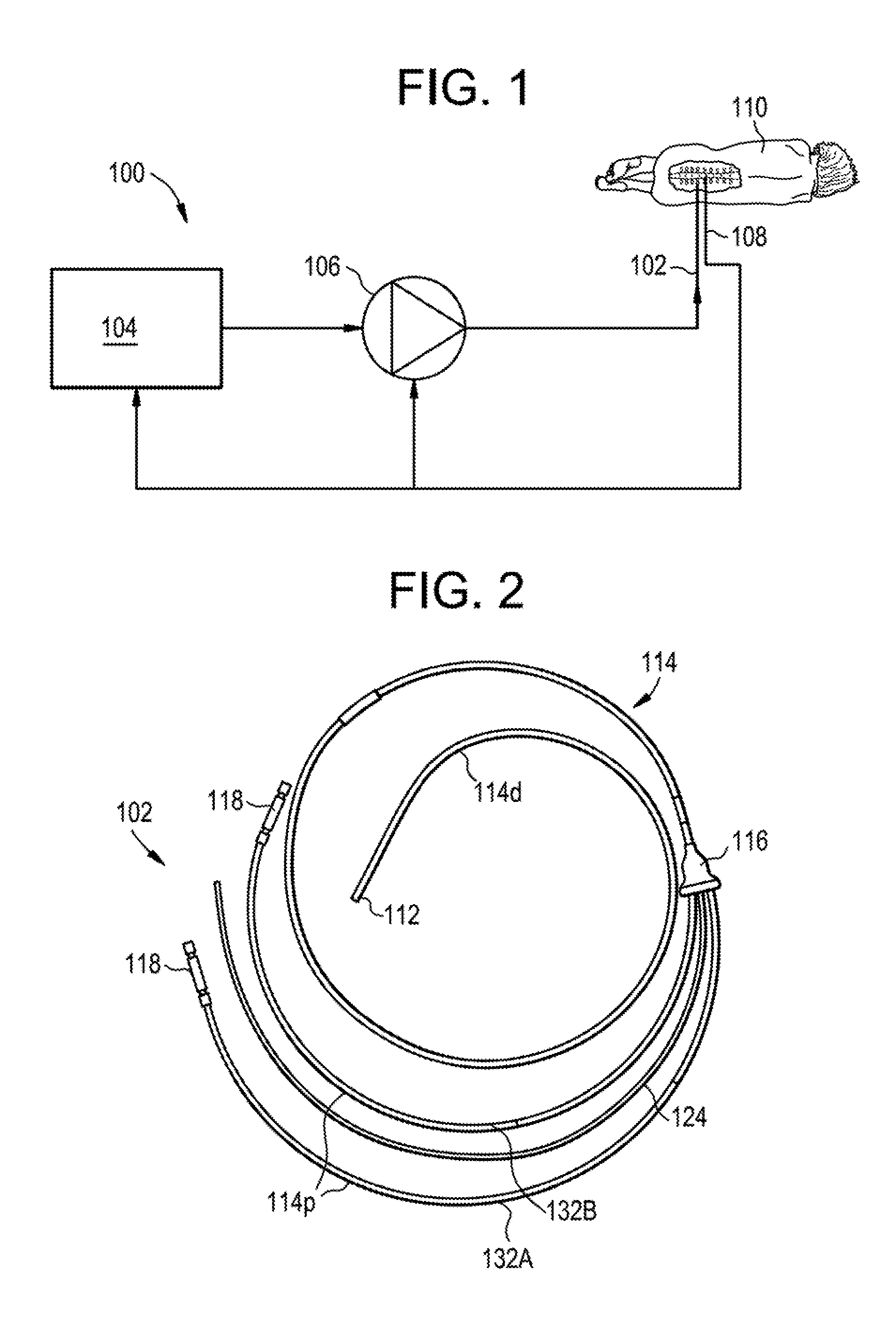
[0155] FIG. 1 is a schematic diagram of an exemplary drug delivery system 100. As shown, the system 100 can include a catheter 102, a controller 104, a pump or actuator 106, and one or more sensors 108. The pump 106 can be configured to pump a drug or a drug-containing fluid through the catheter 102 and into a patient 110 (e.g., into an intrathecal space of the patient). The pump 106 can also be configured to aspirate fluid from the patient. The pump 106 can be controlled by the controller 104 to synchronize or otherwise coordinate delivery of the drug and/or aspiration of fluid with a physiological parameter of the patient, which can be measured by the sensor 108. Exemplary physiological parameters can include heart rate, CSF pressure, CSF pulsation rate, respiration rate, lung capacity, chest expansion and contraction, intrathoracic pressure, intraabdominal pressure, and the like.
[0156] An exemplary catheter 102 which can be used with the system 100 is shown in FIG. 2. The catheter 102 can include a tip portion 112, a body 114, and a hub 116. A first portion 114d of the body 114 can extend between the tip 112 and the distal end of the hub 116. A second portion 114p of the body 114 can extend proximally from the hub 116 to one or more connectors 118 or other features for coupling the catheter 102 to the system 100, e.g., for attaching the catheter to the pump 106. The catheter 102 can have an overall length of about 1 meter.
[0157] The tip 112 of the catheter 102 is shown in more detail in FIGS. 3A-3C. The tip 112 can include a generally cylindrical body with a conical, bulleted, or tapered tip. The tip 112 can provide an atraumatic lead-in surface to facilitate tunneling the catheter 102 through tissue or through a lumen of the patient, such as the intrathecal space. The tip 112 can include one or more fluid lumens formed therein, and a corresponding one or more fluid ports through which fluid can be communicated from the fluid lumen to an exterior of the catheter and vice-versa. In the illustrated embodiment, the tip 112 includes a first fluid lumen 120A with a first fluid pod 122A and a second fluid lumen 120B with a second fluid port 122B, though it will be appreciated that the tip can include any number of fluid lumens (e.g., zero, one, two, three, four, five, more than five, etc.) and any number of fluid ports (e.g., zero, one, two, three, four, five, more than five, etc.). The fluid ports 122A, 122B can be aimed in a substantially distal direction and can be offset from the central longitudinal axis of the tip 112, as shown. In other embodiments, the fluid ports 122A, 122B can be aimed laterally, e.g., in a direction substantially perpendicular to the central longitudinal axis of the tip 112. Having the fluid ports slightly offset from center or aimed laterally can advantageously reduce the risk of the ports becoming occluded during insertion or use of the catheter 102.
[0158] The catheter 102 can include a steering mechanism to facilitate remote positioning of the catheter within the patient. For example, the catheter 102 can be configured to receive a guidewire 124 therethrough to allow the catheter to be inserted over the guidewire or to be steered by the guidewire. In the illustrated embodiment, the tip 112 includes a guidewire lumen 126. The guidewire lumen 126 can be a closed, blind hole as shown, or can be open to an exterior of the tip 112. Alternatively, or in addition, the catheter 102 can include one or more steering wires (not shown) that terminate at the tip 112. The wires can extend proximally from the tip 112 to a proximal end of the catheter 102, where they can be selectively tensioned to steer the tip of the catheter within the patient. For example, the catheter 102 can include first and second steering wires that extend longitudinally therethrough and which are anchored to the tip 112 at diametrically-opposed locations about the outer periphery of the tip. The steering wires can extend through respective sleeves or tubes in the body 114 of the catheter 102 to the proximal end of the catheter where tension can be selectively applied thereto to steer the tip 112 of the catheter.
[0159] The tip 112 can be formed from various materials, including biocompatible materials, stainless steel, titanium, ceramics, polymers, and the like. The tip 112 can be radiopaque or can include one or more radiopaque markers to facilitate visualization under fluoroscopy or other imaging techniques.
[0160] The tip 112 can have an outside diameter of about 3 French to about 5 French. The tip 112 can have an outside diameter of about 1 mm to about 3 mm.
[0161] FIG. 4 is a cross-sectional view of the distal portion 114d of the catheter body 114. As shown, the body 114 can include an outer sheath 128 that defines an interior channel 130. One or more fluid tubes 132A, 132B can be disposed within the interior channel, each fluid tube defining a respective fluid lumen 134A, 134B. The interior channel 130 can also contain a guidewire 124 or one or more steering wires (not shown). In the illustrated embodiment, the distal body portion 114d includes a first fluid tube 132A having a lumen 134A in fluid communication with the first fluid lumen 120A of the tip 112, a second fluid tube 132B having a lumen 134B in fluid communication with the second fluid lumen 120B of the tip, and a guidewire 124.
[0162] The sheath 128 can have various cross-sectional profiles. For example, the sheath 128 can have a circular transverse cross-section that defines a single interior channel 130 as shown. By way of further example, the sheath 128 can have multiple interior channels. Each of the fluid tubes 132A, 132B can be disposed within its own independent channel of the sheath 128, or the sheath itself can define the fluid tubes. The guidewire 124 can be disposed in its own independent channel of the sheath 128 and the fluid tubes 132A, 132B can be disposed in a separate channel of the sheath. The guidewire channel can have a circular cross-section and the fluid tube channel can have a crescent or D-shaped cross-section.
[0163] The fluid tubes 132A, 132B can be formed from any of a variety of materials, including fused silica, polyurethane, etc. Use of fused silica can be advantageous when using the system 100 to deliver viruses, as viruses may be less prone to sticking to fused silica fluid tubes. In some embodiments, fluid tubes used for drug delivery can be formed from fused silica and fluid tubes not used for drug delivery (e.g., buffer delivery tubes or aspiration tubes) can be formed from a material other than fused silica, such as polyurethane. The fluid tubes 132A, 132B can be coated with a shrink tubing or an outer sheath to provide stress and strain relief for the fluid tubes. The sheath 128 can be formed from any of a variety of materials, including polyurethane. While use of the fluid tubes 132A, 132B to communicate fluid is generally described herein, the fluid tubes can also be used for other purposes, such as inserting a biopsy probe or other instrument, or inserting a sensor 108.
[0164] The fluid tubes 132A, 132B can have an inside diameter of about 0.005 inches to about 0.050 inches. The fluid tubes 132A, 132B can have an inside diameter of about 0.010 inches to about 0.020 inches. The body 114 can have an outside diameter of about 3 French to about 5 French. The body 114 can have an outside diameter of about 1 mm to about 3 mm.
[0165] An exemplary hub 116 is shown in FIG. 5. The hub 116 can include respective channels for receiving the first fluid tube 132A, the second fluid tube 132B, and the guidewire 124. Each channel can include proximal and distal openings. The channels can merge within the body of the hub 116 such that they each share a common distal opening. The sheath 128 of the distal body portion 114d can be received through the distal opening of the hub 116 and into the guidewire channel of the hub. The fluid tubes 132A, 132B can penetrate the sidewall of the sheath 128 within the body of the hub 116. The hub 116 can thus form a seal between the sheath 128 and the fluid tubes 132A, 132B, support the fluid tubes and the guidewire 124, and guide these components into the inner channel(s) 130 of the sheath of the distal body portion 114d.
[0166] The hub 116 can be a "pass-through" type hub in which the first and second fluid tubes 132A, 132B extend completely through the hub uninterrupted as shown in FIG. 5. Alternatively, as shown in FIGS. 6A-6B, the first and second fluid tubes 132A, 132B can terminate within the hub at respective connector ports 136A, 136B. The connector ports 136A, 136B can allow selective coupling and decoupling of the proximal body portion 114p (e.g., proximal extension tubes) to the first and second fluid tubes 132A, 132B. The guidewire 124 can continue to extend completely through the hub 116 uninterrupted, or it too can terminate within the hub at a connector where a proximal guide wire extension can be selectively coupled thereto. Any of a variety of connector types can be used to couple the fluid tubes to the proximal extension tubes, including zero-dead-volume micro-connectors or fittings available from Valco Instruments Co. Inc. of Houston, Tex.
[0167] The proximal body portion 114p can include a sheath similar to that of the distal body portion 114d, or can be formed by the fluid tubes 132A, 132B extending proximally from the hub 116, or from one or more extension tubes coupled to the fluid tubes 132A, 132B at the hub 116. The proximal end of the catheter 102 can include one or more connectors 118 for making a fluid connection with the fluid tubes 132A, 132B of the catheter. For example, as shown in FIG. 2, the fluid tubes 132A, 132B (or proximal extension tubes as the case may be) can include a connector 118 at a proximal end thereof. Any of a variety of connector types can be used, including zero-dead-volume micro-connectors or fittings available from Valco Instruments Co. Inc. of Houston. Tex.
[0168] The guidewire 124 can be disposed within the catheter 102 and can be used to guide, steer, or otherwise control insertion of the catheter into the patient.
[0169] The guidewire 124 can be cylindrical and can have a substantially-straight profile. The guidewire 124 can extend completely through the catheter 102, or can terminate in a blind bore 126 formed in the tip 112 of the catheter. In use, the guidewire 124 can be inserted into the patient first and guided to a target site, and the catheter 102 can then be inserted over the guidewire to position a portion of the catheter at the target site. In other embodiments, the catheter 102 can be inserted before or simultaneously with the guidewire 124, and the guidewire can be used to steer or guide the catheter.
[0170] For example, as shown in FIGS. 7A-7C, the guidewire 124 can have a resting configuration that deviates from a straight line at or near a distal end of the guidewire. In FIG. 7A, the guidewire 124 has a straight distal portion 124d and a straight proximal portion 124p joined by a curved elbow such that a central longitudinal axis of the distal portion extends at an oblique angle with respect to a central longitudinal axis of the proximal portion. In FIG. 7B, the guidewire 124 has a curved distal portion 124d joined to a straight proximal portion 124p such that a central longitudinal axis of the distal portion extends at an oblique angle with respect to a central longitudinal axis of the proximal portion. In FIG. 7C, the guidewire 124 has a straight distal portion 124d and a straight proximal portion 124p that meet at an angled bend such that a central longitudinal axis of the distal portion extends at an oblique angle with respect to a central longitudinal axis of the proximal portion.
[0171] In use, the guidewire 124 can be used to navigate the catheter 102 through the patient by twisting the proximal end of the guidewire to turn the bent distal portion and thereby steer or aim the catheter. While a single guidewire 124 is shown, it will be appreciated that the catheter 102 can include any number of guidewires and/or guidewire lumens. The guidewire 124 can be formed from any of a variety of materials, including shape-memory metals such as Nitinol.
[0172] Any of the catheters disclosed herein can be steerable. For example, a steering mechanism can be provided to allow the distal end of the catheter 102 to be guided during insertion or at another desired time. In some embodiments, the catheter 102 can include one or more steering wires having a first end coupled to the distal tip 112 of the catheter and having a second end at the proximal end of the catheter through which tension can be selectively applied to the steering wires to direct or steer the tip of the catheter in a desired direction. The steering wires can be embedded in the sidewalls of the catheter 102 or can extend through a lumen of the catheter.
[0173] In some embodiments, the catheter 102 can include a coaxial steering catheter (not shown) extending therethrough. A distal end of the steering catheter can be curved or biased towards a curved shape such that, when the steering catheter is deployed distally from the tip of the primary catheter 102, the primary catheter can be steered or guided along the curve of the steering catheter. The steering catheter can then be retracted back into the primary catheter 102 to discontinue the curved guidance. The steering catheter can be formed from or can include shape memory or resilient materials such that the steering catheter is deformable between a substantially straight line configuration when retracted into the primary catheter 102 and a flexed or curved configuration when deployed from the primary catheter. The steering catheter can be longitudinally translatable relative to the primary catheter 102 to allow for deployment and retraction.
[0174] Any of the catheters disclosed herein can include a camera or imaging device, which can be integral with the catheter or can be inserted through a working channel of the catheter. Any of the catheters disclosed herein can include markings visible under fluoroscopy, CT, MRI, or other imaging techniques to allow the catheter to be visualized in images captured using such techniques.
[0175] The catheter 102 can be configured to withstand high internal pressures. The catheter 102 can be configured to withstand a pressure of at least about 100 psi, at least about 200 psi and/or at least about 500 psi.
[0176] It will be appreciated that a number of variations on the above-described catheter 102 are possible. For example, one or more of the fluid ports can be aimed to the side such that they exit a lateral sidewall of the catheter. FIGS. 8A-8B illustrate an exemplary catheter tip having side-facing ports. As shown, the tip 112 includes a first fluid lumen 120A that extends to a distal-facing port 122A. The distal-facing port 122A can be formed in an angled or slash-cut distal face of the tip 112. The tip 112 also includes a second fluid lumen 120B that extends to a side-facing port 122B. The tip 112 can also include a guidewire lumen for receiving the distal end of a guide wire 124. In some embodiments, the central channel 130 of the sheath 128 can act as a fluid lumen, e.g., for delivering a buffer or for delivering a drug. The tip 112 can include a side-facing port 122C in fluid communication with the central channel 130 of the sheath 128.
[0177] The catheter 102 can include one or more fluid ports formed proximal to the tip portion 112 of the catheter, e.g., formed in the body 114 of the catheter. FIG. 9 illustrates an exemplary catheter body 114 having a side-facing port 122B. As shown, one or more of the fluid tubes 132A, 132B extending through the sheath 128 of the body 114 can terminate within the body or can otherwise have a fluid port disposed in the body. The sheath 128 can have a slit or opening 122B aligned with the port of the fluid tube 132B, such that fluid exiting the fluid tube can flow through the opening in the sheath or such that fluid can flow through the sheath and into the port of the fluid tube. The catheter 102 can include one or more plugs 138 disposed within the channel 130 of the sheath 128 to prevent fluid exiting or entering the fluid tube 132B from flowing proximally and/or distally within the sheath, instead guiding the fluid out of the sheath through the opening or slit 122B formed therein, or guiding incoming fluid into the fluid port of the tube. The plugs 138 can be formed from a rigid material, from an adhesive, silicone, or various other materials.
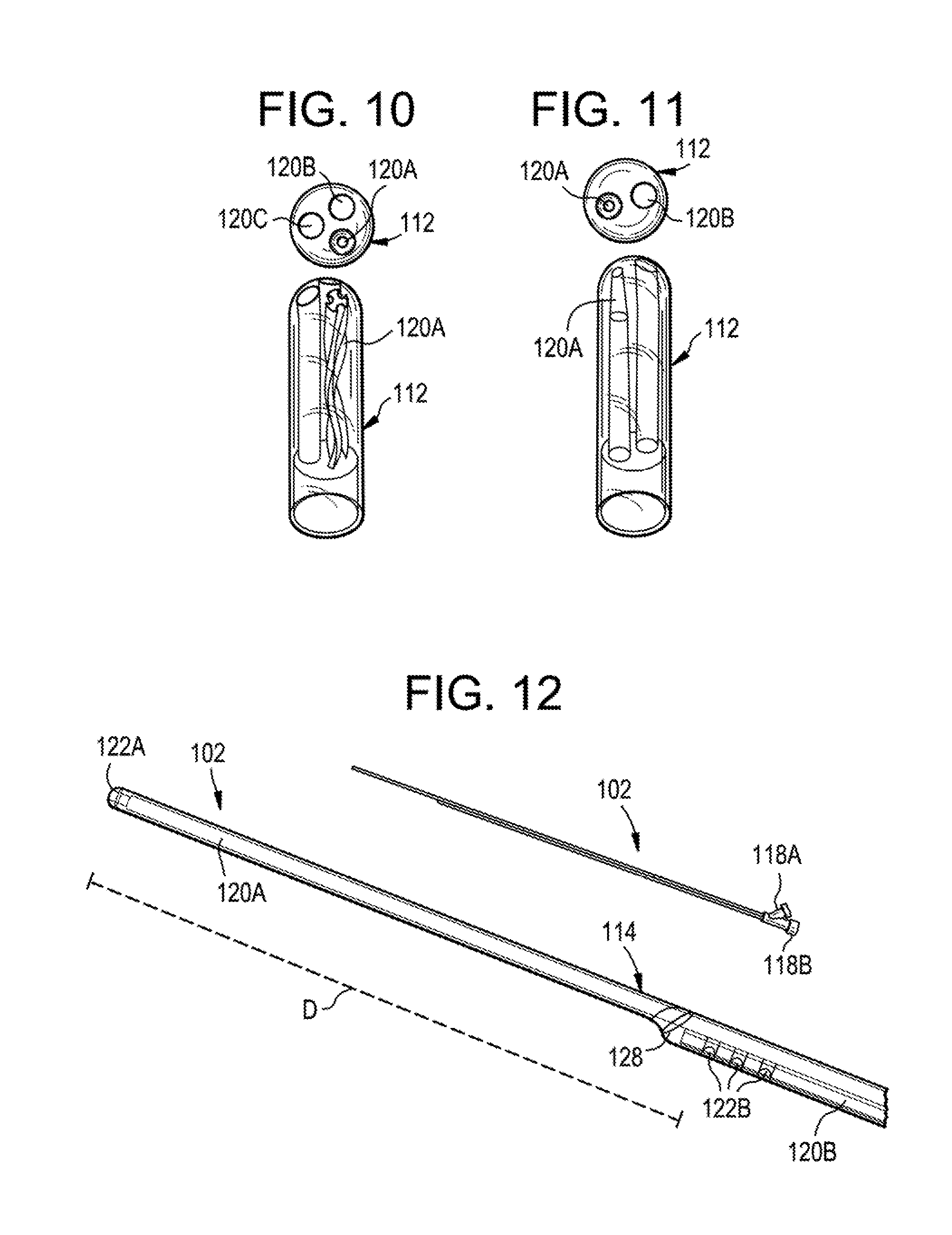
[0178] The fluid lumens of the catheter can have various internal geometries to control or direct the delivery pattern of fluid delivered therethrough. FIG. 10 illustrates an exemplary catheter tip 112 in which one of the fluid lumens 120A has a thread formed on an interior surface thereof to define a helical or "corkscrew" shape. The helical shape of the fluid lumen 120A can promote turbulent flow of fluid therefrom encouraging dispersion or even distribution of the fluid. It will be appreciated that more than one of the fluid lumens can have a helical tip. FIG. 11 illustrates an exemplary catheter tip 112 in which one of the fluid lumens 120A tapers or narrows towards the distal end to create a nozzle. This nozzle can create a jet-stream effect, increasing the velocity of the infusate as it is delivered. It will be appreciated that more than one of the fluid lumens can have a nozzle tip. As also shown in FIGS. 10-11, one or more of the fluid lumens can have a simple cylindrical tip.
[0179] As noted above, the catheter 102 can include any number of lumens extending therethrough. In some embodiments, a dual-lumen catheter can be used. The dual lumen catheter can include an infusion lumen and a pressure sensor lumen, an infusion lumen and an aspiration lumen, two infusion lumens, etc. In other embodiments, a tri-lumen catheter can be used. The tri-lumen catheter can include an infusion lumen, an aspiration lumen, and a pressure sensor lumen, two infusion lumens and an aspiration lumen, three infusion lumens, etc. FIG. 10 illustrates an exemplary tri-lumen catheter having an infusion lumen 120A, an aspiration lumen 1208, and a pressure sensor lumen 120C. FIG. 11 illustrates an exemplary dual-lumen catheter an infusion lumen 120A and an aspiration lumen 120B.
[0180] The catheter can include a valve system to control the direction of fluid flow therethrough. For example, a valve system can include one-way valves on each lumen to prevent infusion into an aspiration lumen and vice versa. The valve system can facilitate use of a single syringe or other pump to infuse and withdraw fluid, or can facilitate infusion and aspiration through a single lumen.
[0181] As discussed further below, the sensor 108 can be mounted to the catheter 102, formed integrally with the catheter, threaded through a lumen of the catheter, etc. For example, the catheter 102 can include a sensor 108 embedded in the tip portion 112 of the catheter, or can include a sensor threaded through a dedicated sensor lumen of the catheter.
[0182] One or more of the fluid lumens through the catheter can have fluid ports that are longitudinally offset from fluid ports of other lumens of the catheter. For example, as shown in FIG. 12, the catheter 102 can include a first fluid lumen 120A that extends to a fluid port 122A formed at the terminal distal end of the catheter. The catheter 102 can also include a second fluid lumen 120B that extends to fluid ports 1228 which are spaced a distance D apart from the distal end of the catheter in a proximal direction. As shown, the second fluid lumen 120B can include one or more side-facing ports 122B. In other embodiments, the second fluid lumen 120B can include a distal facing port. In use, one of the fluid lumens 120A, 1208 can be used to deliver a drug or other fluid and the other fluid lumen can be used to aspirate fluid from the patient. The catheter 102 can thus be used to create a "push-pull" effect at a target site, in which a drug is infused at the distal end of the catheter via the first fluid lumen 120A and then drawn back toward the proximal end of the catheter by the flow of fluid being aspirated through the second fluid lumen 120B. The opposite arrangement can also be used, in which the drug is infused through the proximal port(s) and aspirated through the distal port(s). A proximal end of the catheter 102 can have first and second connectors 118A, 118B corresponding respectively to the first and second fluid lumens 120A, 120B. The offset fluid ports 122A, 122B can be used to coordinate delivery with a physiological parameter of the patient, such as natural CSF flow. An external peristaltic pump or other device can be used to drive the infusion and/or aspiration. As shown, the outer sheath 128 of the body 114 can taper inward to the first lumen 120A after the termination of the second lumen 120B.
[0183] The catheter 102 can include features for controlling delivery of fluid through the catheter. For example, as shown in FIG. 13, the catheter 102 can include an internal auger 140. The auger 140 can have an elongate flexible shaft 142 that extends through the catheter 102 to a proximal end of the catheter, where it can be coupled to a motor for driving rotation of the auger. The motor can be part of the controller 104 or can be a separate component. The controller 104 can start and stop rotation of the auger 140, and/or can control the speed or direction of auger rotation to control delivery of fluid through the fluid lumen 120 in which the auger is disposed. The auger 140 can be disposed in a fluid tube 132 extending through a sheath portion 128 of the catheter 102. The auger 140 can also be disposed distal to a terminal distal end of a fluid tube 132, with the auger shaft 142 extending through the fluid tube. The auger 140 can thus be disposed within the sheath 128 of the catheter 102 but distal to a fluid tube 132 of the catheter. The auger 140 can advantageously control fluid delivery through the catheter 102 and generate more turbulent flow of fluid from the catheter. A proximal end of the catheter can have first and second connectors 118A, 118B corresponding respectively to the first and second fluid lumens and a third port or connector 118C through which the auger shaft 142 can extend. The auger 140 can be used to coordinate delivery with a physiological parameter of the patient, such as natural CSF flow.
[0184] By way of further example, as shown in FIG. 14, the catheter 102 can include an internal, reciprocating piston or inner tube 144. The catheter 102 can include a fixed outer tube 128 and a slidable inner tube 144 disposed coaxially within the outer tube. The inner tube 144 can be configured to translate longitudinally with respect to the outer tube 128. The inner tube 144 can include a valve 146. e.g., at a terminal distal end thereof. Exemplary valves include one-way valves, duck-bill valves, spring-biased check valves, and the like. A seal can be formed between the inner tube 144 and the outer tube 128, e.g., at a proximal end of the catheter 102. In use, the inner tube 144 can be loaded with a drug-containing fluid. The inner tube 144 can then be pulled proximally with respect to the outer tube 128 to cause the drug-containing fluid to flow through a one-way valve 146 into the distal end of the outer tube. The inner tube 144 can then be pushed distally, closing the one-way valve 146 and expelling the drug-containing fluid out of the distal end of the outer tube 128 and into the patient. The translating tubes 128, 144 can allow a fixed or predetermined volume of drug-containing infusate to be delivered with each reciprocation of the inner tube 144. The proximal ends of the outer and inner tubes 128, 144 can include connectors 118A, 118B, e.g., for supplying fluid to the outer and inner tubes. The reciprocating inner tube 144 can be used to coordinate delivery with a physiological parameter of the patient, such as natural CSF flow.
[0185] As another example, as shown in FIG. 15, the catheter 102 can include a transducer 148, such as a piezoelectric transducer, to help control delivery of a drug through the catheter. The transducer 148 can be formed on a flex circuit or other substrate disposed adjacent to a fluid port 122 of the catheter 102. The transducer 148 can include an electrically-conductive lead or wire 150 that extends proximally therefrom through the catheter 102 to the controller 104. In use, an electric potential can be applied to the transducer 148 to induce vibration or other movement of the transducer. This movement can control distribution of the drug from the catheter 102. For example, the transducer 148 can control the direction in which the infusate flows as it exits the catheter 102, can control the opening or closing of a fluid port 122 of the catheter, and/or can control the volume of infusate that exits the catheter. A proximal end of the catheter 102 can have first and second connectors 118A, 118B corresponding respectively to first and second fluid lumens and a third port or connector 118C through which the electrical conductor 150 of the transducer 148 can extend. The transducer 148 can be used to coordinate delivery with a physiological parameter of the patient, such as natural CSF flow.
[0186] The system 100 can include one or more transducers for delivering focused ultrasound to the patient. As shown in FIG. 16, a focused ultrasound system 152 can aim ultrasonic waves toward a location at which drug-containing infusate 154 exits the catheter 102. The focused ultrasound can enhance dispersion of the drug, and/or control the direction and degree to which the drug disperses. Focused ultrasound can be used to coordinate delivery with a physiological parameter of the patient, such as natural CSF flow. Focused ultrasound can also be used to enhance or direct drug distribution without pulsatile delivery.
[0187] FIG. 17 illustrates a block diagram of the physical components of an exemplary embodiment of the controller 104. Although an exemplary controller 104 is depicted and described herein, it will be appreciated that this is for sake of generality and convenience. In other embodiments, the controller 104 may differ in architecture and operation from that shown and described here. The controller 104 can be a tablet computer, mobile device, smart phone, laptop computer, desktop computer, cloud-based computer, server computer, and so forth. One or more portions of the controller 104 can be implanted in the patient. Delivery control software can execute on the controller 104. The software can execute on a local hardware component (e.g., a tablet computer, smart phone, laptop computer, or the like) or can execute remotely (e.g., on a server or cloud-connected computing device in communications coupling with the controller).
[0188] The illustrated controller 104 includes a processor 156 which controls the operation of the controller 104, for example by executing embedded software, operating systems, device drivers, application programs, and so forth. The processor 156 can include any type of microprocessor or central processing unit (CPU), including programmable general-purpose or special-purpose processors and/or any of a variety of proprietary or commercially-available single or multi-processor systems. As used herein, the term processor can refer to microprocessors, microcontrollers, ASICs, FPGAs, PICs, processors that read and interpret program instructions from internal or external memory or registers, and so forth. The controller 104 also includes a memory 158, which provides temporary or permanent storage for code to be executed by the processor 156 or for data that is processed by the processor. The memory 158 can include read-only memory (ROM), flash memory, one or more varieties of random access memory (RAM), and/or a combination of memory technologies. The various components of the controller 104 can be interconnected via any one or more separate traces, physical busses, communication lines, etc.
[0189] The controller 104 can also include an interface 160, such as a communication interface or an I/O interface. A communication interface can enable the controller 104 to communicate with remote devices (e.g., other controllers or computer systems) over a network or communications bus (e.g., a universal serial bus). An I/O interface can facilitate communication between one or more input devices, one or more output devices, and the various other components of the controller 104. Exemplary input devices include touch screens, mechanical buttons, keyboards, and pointing devices. The controller 104 can also include a storage device 162, which can include any conventional medium for storing data in a non-volatile and/or non-transient manner. The storage device 162 can thus hold data and/or instructions in a persistent state (i.e., the value is retained despite interruption of power to the controller 104). The storage device 162 can include one or more hard disk drives, flash drives, USB drives, optical drives, various media disks or cards, and/or any combination thereof and can be directly connected to the other components of the controller 104 or remotely connected thereto, such as through the communication interface. The controller 104 can also include a display 164, and can generate images to be displayed thereon. In some embodiments, the display 164 can be a vacuum fluorescent display (VFD), an organic light-emitting diode (OLED) display, or a liquid crystal display (LCD). The controller 104 can also include a power supply 166 and appropriate regulating and conditioning circuitry. Exemplary power supplies include batteries, such as polymer lithium ion batteries, or adapters for coupling the controller 104 to a DC or AC power source (e.g., a USB adapter or a wall adapter).
[0190] The various functions performed by the controller 104 can be logically described as being performed by one or more modules. It will be appreciated that such modules can be implemented in hardware, software, or a combination thereof. It will further be appreciated that, when implemented in software, modules can be part of a single program or one or more separate programs, and can be implemented in a variety of contexts (e.g., as part of an embedded software package, an operating system, a device driver, a standalone application, and/or combinations thereof). In addition, software embodying one or more modules can be stored as an executable program on one or more non-transitory computer-readable storage mediums. Functions disclosed herein as being performed by a particular module can also be performed by any other module or combination of modules, and the controller can include fewer or more modules than what is shown and described herein. FIG. 18 is a schematic diagram of the modules of one exemplary embodiment of the controller 104.
[0191] As shown in FIG. 18, the controller 104 can include a sensor input module 168 configured to receive information from the sensor(s) 108. The sensor input module 168 can read and interpret output signals supplied from the sensors 108 to the processor 156, e.g., via a general purpose input/output pin of the processor. The sensor input module 168 can optionally perform various processing on the sensor signals, such as frequency detection, phase detection, debouncing, analog-to-digital conversion, filtering, and so forth.
[0192] The controller 104 can also include a delivery control module 170 configured to control the pump or actuator 106 to infuse or aspirate fluid from the patient and/or to control the catheter 102 (e.g., an auger, piston, transducer, ultrasound system, etc.). For example, when an "infuse" instruction is issued, the delivery control module 170 can cause power to be supplied to the pump 106 to begin pumping infusate through the catheter 102, or cause an electronically-actuated valve to open such that infusate stored under pressure is placed in fluid communication with the catheter and flows therethrough. In some embodiments, the delivery control module 170 can be configured to cut off power to the pump 106 or to close a valve when a pressure sensor indicates that the pressure in the system has reached a predetermined threshold amount. When an "aspirate" instruction is issued, the delivery control module 170 can cause power to be supplied to the pump 106 to begin pumping fluid out of the catheter 102.
[0193] The controller 104 can include a user input module 172 configured to receive one or more user inputs, e.g., as supplied by a user via the interface 160. Exemplary user inputs can include infusion parameters, patient information, treatment protocols, and so forth, as discussed further below.
[0194] The controller 104 can also include a display module 174 configured to display various information to the user on the display 164, such as a graphical or textual user interface, menus, buttons, instructions, and other interface elements. The display module 174 can also be configured to display instructions, warnings, errors, measurements, and calculations.
[0195] FIG. 19 illustrates an exemplary graphical user interface 176 that can be displayed to the user by the display module 174 and through which a user can supply information to the user input module 172. The illustrated interface 176 is configured for use with a pump system 106 that includes first and second motors or linear actuators that can be operated to apply a force to respective syringe pumps for delivering infusate to the catheter 102 and for withdrawing or aspirating fluid from the catheter.
[0196] The user interface 176 can include a motor communication panel 178 for displaying various information associated with the motors. This information can include the connection status of the motors, an IP or other software address of the motors, and a motor communication frequency or update time. The user can interact with the motor communication panel 178 to select or change the motor addresses and the update time.
[0197] The user interface 176 can include a motor setting panel 180 for adjusting various motor settings and for displaying the current setting to the user. The motor setting panel 180 can include controls for the motor velocity, motor acceleration, distance of syringe movement as a function of motor steps, current motor positions, infusion frequency, infusion amplitude, infusion rate, infusion phase, and so forth.
[0198] The controller 104 can be configured to control various infusion and/or aspiration parameters to achieve customized delivery. This can allow the delivery to be tailored based on the therapeutic application. Exemplary parameters that can be controlled by the controller 104 include infusion type, infusion rate, infusion volume, time between infusions, oscillatory rate, infusion and withdraw ratio, infusion phase timing, aspiration type, aspiration rate, time between aspirations, aspiration volume, and so forth.
[0199] The pump or actuator system 106 can be configured to supply a drug or a drug-containing fluid to the catheter 102 and/or to aspirate fluid from the catheter. The system 106 can include one or more pumps. For example, the system 106 can include a plurality of pumps, each being associated with and in fluid communication with a corresponding lumen of the catheter 102. The pumps can also be associated with and in fluid communication with respective reservoirs for holding a volume of fluid. In some embodiments, the system 106 can include first and second syringe pumps coupled to electronic linear actuators configured to advance or retract the plungers of the syringe pumps in response to control signals received from the controller 104. In some embodiments, the system 106 can include a peristaltic pump, an auger pump, a gear pump, a piston pump, a bladder pump, etc. One or more portions of the system 106 can be implanted in the patient. The system 106 can include any of a variety of implantable or extracorporeal pumps. In some embodiments, the system 106 can include a fully-implanted, programmable pump and a fully-implanted fluid reservoir containing fluid to be delivered using the system. In some embodiments, the entire system 106 can be implantable, e.g., to facilitate chronic treatment methods.
[0200] The sensor 108 can be a single sensor or a plurality of sensors. Exemplary sensors include pressure sensors, electrocardiogram sensors, heart rate sensors, temperature sensors, PH sensors, respiration rate sensors, respiration volume sensors, lung capacity sensors, chest expansion and contraction sensors, intrathoracic pressure sensors, intraabdominal pressure sensors, and the like. One or more of the sensors 108 can be implanted in the patient. One or more of the sensors 108 can be mounted on, inserted through, or formed in or on the catheter 102. The sensors 108 can also be remote from the catheter 102. In some embodiments, the sensors 108 can include a pressure sensor disposed in or on the catheter 102 for measuring CSF pressure adjacent to the catheter and an ECG sensor for measuring the patient's heart rate. The sensors 108 can be connected (via wires or via a wireless connection) to the sensor input module 168 of the controller 104.
[0201] As noted above, one or more components of the delivery system 100 and, in some embodiments, all components of the delivery system, can be implanted in the patient. Implanting some or all of the delivery system 100 can facilitate chronic or long-term drug delivery (e.g., over a period of days, weeks, months, or years) via non-invasive or outpatient procedures.
[0202] FIGS. 20A-20B illustrate the catheter 102 fully-implanted in a patient. As shown, the catheter 102 can be configured for positioning within a patient's intrathecal space and can extend substantially the entire length of the spinal column or along any portion thereof. The catheter 102 can include one or more fluid lumens. The catheter 102 can also include one or more fluid ports. In some embodiments, the catheter 102 can include a plurality of fluid lumens, with each of the plurality of fluid lumens having its own respective fluid port. In the illustrated embodiment, the catheter 102 includes three fluid lumens and three respective fluid ports 122P, 122M, and 122D. The catheter 102 can also include one or more sensors 108 (e.g., pressure sensors). In the illustrated embodiment, each of the fluid ports 122P, 122M, 122D includes a sensor 108P. 108M, 108D mounted adjacent or in proximity thereto. A proximal end of the catheter 102 can be coupled to a fully implanted, transcutaneous, or extracorporeal infusion port 182 through which fluid can be delivered to (or removed from) the various lumens of the catheter and through which one or more sensors 108 on the catheter can be coupled to a controller 104 or other device. A quick-connector system 184 can be used to couple the catheter 102 to the infusion port 182. The micro-connector 184 can include air and/or bacterial filters and can be a zero-dead-volume connector. The pump 106 and the controller 104 can be mounted together in a chassis or housing 188, as shown in FIG. 20C, which can be coupled to an injector 190 configured to mate with the infusion port 182. The injector 190 can include magnetic alignment features 186 for ensuring that the injector is properly aligned with respect to a subcutaneous infusion port 182.
[0203] As shown in FIG. 20D, the distal or cranial/cervical tip of the catheter 102 can have a modified shape to encourage turbulent flow therethrough (e.g., a helical or corkscrew shaped lumen or fluid port 122D as described above). Any of a variety of other shapes can be used. The other ports 122M, 122P can be similarly configured, can have a simple circular cross-section as shown in FIG. 20E, or can have any other configuration described herein.
[0204] The system 100 illustrated in FIGS. 20A-20E can be used in acute and/or chronic applications in any of a variety of ways.
[0205] For example, the catheter 102 can be used to deliver three different drugs (e.g., one drug through each different lumen of the catheter).
[0206] By way of further example, the catheter 102 can be used for localized delivery of different drugs to different areas of the spine.
[0207] As yet another example, the catheter 102 can be used to deliver the same drug with substantially instantaneous distribution along the entire spinal column.
[0208] In another example, one port of the catheter 102 can be used to aspirate while another is used to infuse in order to draw the infused fluid through the spinal canal. In some embodiments, fluid can be infused through a lower-lumbar port 122P and fluid can be aspirated through a cervical port 122D to "pull" the infused fluid up the spinal column.
[0209] In another example, fluid can be infused through a port 122D disposed in the cervical region of the patient's spine to propel infused drug into the cranial space.
[0210] By way of further example, the catheter 102 can be used to substantially contain an infused drug to a given area of the spine. In some embodiments, fluid can be infused through a lower-lumbar port 122P and fluid can be withdrawn from a mid-lumbar port 122M to keep the infused drug between the two ports 122P, 122M in the lumbar region of the patient's spine.
[0211] In an exemplary method, infusions and aspirations via multiple lumens and ports can be staged or combined in a sequence to create and advance a significant bolus at improved, controlled, and convenient rates. The method can include simultaneous aspiration/infusion between deliberately spaced ports. The delivery can be enhanced by a preparation step of removing a safe amount of CSF to be replaced in later procedure steps when advancing the bolus. The method can include a final stage of synchronized pulsatile infusion. The method can allow a large bolus to be formed more quickly, can allow controlled dosing, and/or can allow the bolus to be delivered closer to the brain or other target site. The method can be performed using a catheter that tapers from the proximal end towards the distal end. A tapered catheter profile in which the catheter diameter reduces distal of each port can enable the catheter to be longer, be easier to introduce/navigate, and have device reach significantly closer to the target site. Port designs and locations can be optimized based on dose and other factors. The catheter can be placed such that fluid exiting the ports flows against patient anatomy (e.g., a blind lumen end, lumen sidewall, or lumen constriction) to promote turbulent flow of the infusate upon exiting the catheter. In an initial step, a volume of patient CSF can be aspirated through one or more ports of the catheter. In an exemplary embodiment, about 10% by volume of the patient's CSF can be aspirated through the catheter and stored in a reservoir. The amount of CSF that is aspirated can be based on a clinically-determined safe level. In a subsequent delivery step, CSF can be aspirated from the patient through a distal fluid port 122D of the catheter 102 while a drug is simultaneously infused into the patient through a middle port 122M of the catheter. This can cause a bolus of drug to form between the middle and distal ports 122M, 122D. The ports can be located along the length of the catheter to define the bolus size or dose. In an advancement step, the bolus of drug can be advanced within the patient. This can be achieved by infusing previously-aspirated CSF from the reservoir into the patient through a proximal port 122P of the catheter 102. This infusion can urge the bolus distally towards the target site and can continue until normal or safe CSF pressure is reached within the patient. While previously-aspirated CSF is used to advance the bolus in the above example, other fluid can be used instead or in addition, such as drug-containing fluid. Before, during, or after advancement of the bolus, infusion of CSF and/or drug-containing fluid can be performed in a pulsatile manner in coordination with one or more physiological parameters of the patient. The above method can also be performed using only a proximal port 122P and a distal port 122D. The proximal, middle, and distal ports 122P, 122M, 122D can be spaced along the length of the spinal column as shown in FIG. 20A, or can all be contained in a discrete region of the spine (e.g., the cervical spine, the thoracic spine, the lumbar spine, etc.).
[0212] The systems disclosed herein can be used in any of a variety of drug delivery methods.
[0213] In an exemplary method, the infusion pump 106 can be configured to pump a drug or a drug-containing fluid through the catheter 102 and into a patient (e.g., into an intrathecal space of the patient). The catheter 102 can be inserted into the patient at any of a variety of locations. For example, a percutaneous puncture can be formed in the patient using a needle. The puncture can be formed in the lumbar region of the spine, or in any other region of the spine, e.g., the cervical region between CI and C2. The needle can have a bent distal tip that helps steer the catheter 102 to be parallel to the spinal cord. The catheter 102 can be inserted through the needle and guided through the intrathecal space along the spinal cord. The infusion can be performed in proximity to the percutaneous puncture, or the catheter 102 can be advanced some distance within the patient. In some embodiments, the catheter 102 can be inserted in the lumbar spine and advanced to the cervical spine or to the cisterna magna. Infusion can be performed at any point along the length of the catheter 102. Fluid can be infused from a distal end of the catheter 102 (e.g., in a cervical region of the spine), the catheter can be withdrawn proximally, and further infusion can be performed at a more caudal location (e.g., in a lumbar region of the spine).
[0214] The pump 106 can be controlled by the controller 104 to synchronize or otherwise coordinate delivery of the drug with the patient's natural CSF flow or pulsation, or with other physiological parameters of the patient (e.g., heart rate, respiration rate, lung capacity, chest expansion and contraction, intrathoracic pressure, intraabdominal pressure, etc.). The infusion profile can be tailored to override the natural CSF pulsation to drive the infusate to a target site. Alternatively, or in addition, the infusion profile can be tailored to coordinate with and leverage the natural CSF pulsation to move the infusate towards the target site.
[0215] Readings from a pressure sensor 108 can be received by the controller 104, which can perform signal processing on the sensor output to determine various characteristics of the patient's CSF flow (e.g., phase, rate, magnitude, etc.). The controller 104 can then control the pump 106 based on these measured characteristics to deliver a drug in coordination with the natural CSF flow, optionally synchronizing the delivery in real time. For example, as shown in the upper portion of FIG. 21A, the controller 104 can convert the measured pulsatile flow of the CSF into a sinusoidal approximation. The controller 104 can then output a pump control signal, as shown in the lower portion of FIG. 21A, to drive the infusion pump 106 in coordination with the CSF pulsation.
[0216] In some instances, the pressure sensed by the pressure sensor 108 can be influenced by the infusion through the catheter 102. Accordingly, it can be desirable to have another way of detecting or estimating CSF flow. Thus, in some embodiments, the system 100 can be operated initially in a "learning" mode in which no infusion takes place and the controller 104 establishes a correlation between CSF pulsation and heart rate (e.g., as detected by an ECG sensor 108 in communications coupling with the controller). In general, CSF pulsation tracks heart rate with a slight delay. Once a con-elation is established, the system 100 can be operated in an "infusion" mode in which infusate is delivered through the catheter 102 and the CSF pulsation is detected or estimated based on measured heart rate (instead of or in addition to detecting or estimating the CSF pulsation based on the pressure sensor 108 output). In other words, the system 100 can interpolate or estimate the CSF flow based on the ECG output, without necessarily having to rely on the pressure sensor output. This can allow the pressure sensor to be used for other purposes, such as monitoring the infusion pressure to allow the controller 104 to automatically regulate delivery to a target pressure or pressure range.
[0217] In one example use of the systems described herein, a drug can be delivered to the intrathecal space via a simple bolus injection (a fast infusion of a volume of fluid) which then just diffuses slowly along the spinal column.
[0218] In another example, a bolus injection can be performed to deliver the drug and then the system can be used to create a pulsation behind the bolus by changing oscillation rate/pulsation rate to override the natural CSF pulse and make the bolus move more quickly towards a target location (e.g., the brain). The pulsation can be created by repeatedly withdrawing or aspirating a volume of CSF and then pumping that same volume back into the patient to create a pulse.
[0219] In another example, infusion of the drug itself can be used to create a pulsation effect to urge the drug along the intrathecal space. In this example, a first volume of the drug can be infused (e.g., 0.1 ml) and then a second, smaller volume can be withdrawn (e.g., 0.05 ml). This can be repeated to create a pulse with a net infusion on each cycle. The process can be repeated until the desired dose is delivered. While an infusion-to-withdrawal ratio of 2:1 is discussed above, it will be appreciated that any ratio can be used. In addition, the rate of infusion and withdrawal can be controlled (e.g., by infusing quickly and withdrawing slowly) to create a burst of fluid towards a target location (e.g., the top of the spinal column).
[0220] In the devices and methods disclosed herein, infusion and/or aspiration can be coordinated with one or more physiological parameters of a patient (e.g., natural CSF flow, heart rate, respiration rate, etc.).
[0221] The direction of drug distribution at an intrathecal target site can be controlled at least to some degree based on the timing at which the drug is delivered relative to the timing of the CSF flow. For example, infusion that is synchronized with the ascending wave of CSF flow, as shown in FIG. 21 B, can be distributed to a greater degree in the cranial direction whereas infusion that is synchronized with the descending wave of CSF flow, as shown in FIG. 21C, can be distributed to a greater degree in the caudal direction of the spinal canal.
[0222] In some embodiments, a dual- or multi-lumen catheter can be used for alternating, repetitive infusion and aspiration, which can further enhance drug distribution.
[0223] The systems and methods disclosed herein can provide an improved means for delivering a drug to the intrathecal space, as compared with traditional lumbar bolus injections which do not reach the remote portions of the spinal canal or brain efficiently (if at all).
[0224] While intrathecal delivery is generally described in the examples given above, it will be appreciated that the systems and methods herein can be used in other applications, with appropriate modification of size or other parameters as will be appreciated by those having ordinary skill in the art. For example, the systems and methods disclosed herein can be used for intrarterial or intravenous delivery. Such systems and methods can include infusion and/or aspiration that is coordinated with one or more physiological parameters of a patient (e.g., natural CSF flow, heart rate, respiration rate, etc.).
[0225] In some embodiments, the drug can be delivered in a non-pulsatile manner and/or without necessarily coordinating the delivery with a physiological parameter of the patient. For example, alternating or otherwise-coordinated aspiration and infusion can be used to deliver the drug to a target site. By way of further example, the drug can be infused and then a buffer can be infused behind the drug to enhance distribution or to move the drug towards a target site.
[0226] An exemplary method can include inserting at least a portion of a catheter into a patient and delivering a drug to a target region of the patient. At least a portion of the catheter can be disposed in the target region. The drug can be delivered in a pulsatile manner. The drug can be delivered in coordination with a physiological parameter of the patient (e.g., the patient's natural CSF flow and/or the patient's heart rate).
[0227] The target region can be an intrathecal space of the patient. The target region can be a subpial region of the patient (e.g., a subpial region of the spinal cord and/or a subpial region of the brain). The target region can be a cerebellum of the patient. The target region can be a dentate nucleus of the patient. The target region can be a dorsal root ganglion of the patient. The target region can be a motor neuron of the patient. The drug can include an antisense oligonucleotide. The drug can include a stereopure nucleic acid. The drug can include a virus. The drug can include adeno-associated virus (AAV). The drug can include a non-viral gene therapy. The drug can include vexosomes. The drug can include liposomes. The method can include performing gene therapy by delivering the drug (e.g., by delivering a virus such as AAV). The method can include performing gene editing by delivering the drug (e.g., by delivering a virus such as AAV). The method can include performing gene switching by delivering the drug (e.g., by delivering a virus such as AAV). The method can include performing non-viral gene therapy by delivering the drug (e.g., by delivering vexosomes and/or liposomes).
[0228] In some embodiments, the method can include determining a total CSF volume of the patient and tailoring the delivery based on the total CSF volume. For example, MRI or other imaging techniques, with or without contrast, can be used to assess the overall CSF volume of the patient. The delivery of the drug can then be tailored based on the measured volume. For example, a larger volume of buffer can be used with patients having a greater total CSF volume and a smaller volume of buffer can be used with patients having a lesser total CSF volume. By way of further example, infusion amplitude, infusion velocity, aspiration volume, aspiration amplitude, and other parameters can be varied in accordance with the measured total CSF volume.
[0229] The infusion volume can range from about 0.05 mL and about 50 mL. The infusion rate can range from about 0.5 mL/min to about 50 mL/min.
[0230] The following are exemplary drug delivery methods that can be performed using the systems disclosed herein:
EXAMPLE A
[0231] Alternating Pulsatile infusions of Drug (Pump 1) and Buffer/Saline (Pump 2)
[0232] Drug Total Volume: 2.2 mL
[0233] Buffer Total Volume: 4.4 mL
[0234] Infusion rate for both pumps: 15 mL/min
[0235] Cycles: 10 cycles at lumbar then 10 cycles at Cisterna magna
[0236] Time between cycles: 100 milliseconds
[0237] Infusion description: At lumbar section Pump 1 infuses 0.11 mL at 15 mL/min, a 100 ms pause, Pump 2 infuses 0.22 mL at 15 mL/min, a 100 ms pause (cycle 1). This is repeated for a total of 10 cycles at the lumbar. Catheter is threaded up to the cisterna magna. Pump 1 infuses 0.11 mL at 15 mL/min, a 100 ms pause, Pump 2 infuses 0.22 mL at 15 mL/min, a 100 ms pause (cycle 1). This is repeated for a total of 10 cycles at the cisterna magna.
EXAMPLE B
[0238] Alternating Pulsatile infusions of Drug (Pump 1) and Buffer/Saline (Pump 2)
[0239] Drug Total Volume: 3 mL
[0240] Buffer Total Volume: 20 mL
[0241] Infusion rate for both pumps: 4 mL/min
[0242] Cycles: 13 cycles at thoracic region
[0243] Time between alternating pump 1 to pump 2: 1000 milliseconds
[0244] Time between cycles (pump 2 to pump 1): 5000 milliseconds
[0245] Infusion description: At lumbar section Pump 1 infuses 0.231 mL at 4 mL/min, a 1000 ms pause, Pump 2 infuses 2.0 mL at 4 mL/min, a 5000 ms pause (cycle 1). This is repeated for a total of 13 cycles at the thoracic region.
EXAMPLE C
[0246] Alternating Pulsatile infusions of Drug (Pump 1) and Buffer/Saline (Pump 2)
[0247] Drug Total Volume: 5 mL
[0248] Buffer Total Volume: 8 mL
[0249] Infusion rate for pump 1: 37 mL/min
[0250] Infusion rate for pump 2: 20 mL/min
[0251] Cycles: 5 cycles at thoracic region
[0252] Time between cycles: 10 milliseconds
[0253] Infusion description: At lumbar section Pump 1 infuses 1 mL at 37 mL/min, a 10 ms pause, Pump 2 infuses 1.6 mL at 30 mL/min, a 100 ms pause (cycle 1). This is repeated for a total of 5 cycles at the thoracic region.
[0254] FIG. 22 illustrates a drug delivery system 200 that includes a lumbar puncture needle 292. The needle 292 can include a sensor 294 (e.g., a pressure sensor) mounted adjacent a distal tip of the needle. Accordingly, upon insertion of the needle 292 into the patient 210, the sensor 294 can measure the pressure or other properties of the patient's CSF. The needle 292 can also include an integrated or remote display 296 for displaying the output of the sensor 294 to a user. In some embodiments, the display 296 can be mounted along the length of the needle 292, distal to a proximal Luer or other connector 298 of the needle. The needle body 292 can be a tubular metal shaft with a sharpened or angled tip. Fluid tubing can be coupled to the needle 292, e.g., via a proximal connector 298, and to a programmable pump 106. A controller 104 of the type described above can be programmed to control the pump 106 to deliver fluid through the needle 292, e.g., in a pulsatile fashion in coordination with a physiological parameter of the patient. The needle 292 can be used to deliver a drug, to deliver a buffer, and/or to aspirate fluid. In some embodiments, a catheter 102 of the type described above can be inserted through the needle 292 and the fluid delivery or aspiration can be performed through the catheter.
[0255] As shown in FIG. 23, a manual pump 206 can be provided instead of or in addition to the programmable pump 106 and controller 104 shown in FIG. 22. As shown, a first fluid lumen of the needle 292 (or of a catheter 102 inserted through the needle) can be coupled to a first pump 206A that includes a first reservoir and a first flush dome. Similarly, a second fluid lumen of the needle 292 (or of a catheter 102 inserted through the needle) can be coupled to a second pump 206B that includes a second reservoir and a second flush dome. A user can exert manual finger pressure on the first and second flush domes to selectively press fluid contained in the first and second reservoirs into the patient. Accordingly, the user's manual actuation rate and actuation pressure can dictate the infusion frequency and volume. A user can thus pulse the delivery manually. The flush domes can be configured such that each successive actuation of the dome delivers a fixed and predetermined volume of fluid. For example, each push of the flush dome can be configured to deliver 0.1 ml of fluid. In some embodiments, one of the reservoirs can be filled with a buffer solution and the other reservoir can be filled with a drug-containing solution.
[0256] FIGS. 24A-24G illustrate a drug delivery system 300 that can include a needle 302 and a catheter 304 insertable through the needle. The needle 302 can be a lumbar puncture needle. The catheter 304 can be a single lumen catheter or a multi-lumen catheter. For example, a dual-lumen catheter that bifurcates at a proximal portion of the catheter can be used as shown. Fluid tubing 306 can be coupled to the catheter 304, e.g., via one or more proximal connectors 308, and to a programmable pump system 310. The needle 302 or catheter 304 can also be connected directly to the pump system 310.
[0257] In some embodiments, the pump system 310 can include first and second pumps configured to infuse and/or aspirate fluid through respective lumens of the catheter 304. Any of a variety of pumps can be used, including a linear-actuator syringe pump of the type shown in FIG. 24A. A controller 104 of the type described above can be programmed to control the pump system 310 to deliver fluid through the catheter 304, e.g., in a pulsatile fashion in coordination with a physiological parameter of the patient. The catheter 304 can be used to deliver a drug, to deliver a buffer or other fluid, and/or to aspirate fluid. In some embodiments, the catheter 304 can be omitted and fluid can be infused through the needle 302 directly and/or aspirated through the needle directly. One or more of the fluid connections can be made with the needle 302 instead of or in addition to the catheter 304. For example, the fluid tubing through which a drug is to be delivered can be coupled directly to the catheter 304 to deliver the drug through the catheter and fluid tubing through which a buffer, chaser, or other fluid is to be delivered can be coupled directly to the needle 302 to deliver the fluid through the needle.
[0258] The needle 302 can be defined by a hollow tubular body configured to receive a catheter and/or fluid therethrough. The needle 302 can be a lumbar puncture needle sized and configured for insertion into the intrathecal space through a lumbar insertion point. The needle 302 can have a curved distal tip configured to naturally steer the needle into the intrathecal space as the needle is inserted into the patient in the lumbar region of the spine. An opening can be formed in the distal end of the needle 302 through which an inserted catheter 304 can extend.
[0259] The proximal end of the needle can be coupled to a fluid hub 312. As shown in FIG. 24B, the hub 312 can be a "W" hub. The hub 312 can include a plurality of ports. The hub 312 can include a distal port to which the needle 302 can be attached and placed in fluid communication with the hub. The hub 312 can include one or more proximal ports. The proximal ports can guide a catheter 304 inserted though the hub 312 into the central lumen of the needle 302. The proximal ports can attach the hub 312 to respective fluid lines and place the hub in fluid communication with said fluid lines. The fluid lines can be used to direct fluid into the hub 312 and through a needle 302 attached thereto. The proximal and distal ports of the hub 312 can be Luer type connectors or zero-dead-volume connectors. As shown in FIG. 24B, the hub 312 can include a distal port attached to the needle 302 and a proximal port through which a dual-lumen catheter 304 is inserted to guide the catheter through the needle. The dual lumen catheter 304 can split or bifurcate at a location proximal to the hub 312 into first and second fluid lines, e.g., for carrying a drug and a buffer, respectively. The hub 312 can include one or more additional ports through which a fluid can be introduced into, or withdrawn from, the needle 302. These ports can be used to deliver drug or buffer to the needle 302 or to aspirate fluid from the needle, instead of or in addition to doing so using the catheter 304.
[0260] As shown in FIGS. 24C-24D, the hub 312 can be a "Y" hub. The hub 312 can include a distal port attached to the needle 302 and a proximal port through which a dual-lumen catheter 304 is inserted to guide the catheter through the needle. The dual lumen catheter 304 can split or bifurcate at a location proximal to the hub 312 into first and second fluid lines, e.g., for carrying a drug and a buffer, respectively. The hub 312 can include one or more additional ports through which a fluid can be introduced into, or withdrawn from, the needle 302. These ports can be used to deliver drug or buffer to the needle 302 or to aspirate fluid from the needle, instead of or in addition to doing so using the catheter 304.
[0261] In some embodiments, the hub can be omitted and fluid can be delivered to or aspirated from the needle 302 directly. For example, the needle 302 can be directly attached to the pump system 310 via one or more fluid lines, or a catheter 304 can be directly attached to the pump system via one or more fluid lines and inserted through the needle without a proximal hub.
[0262] The system 300 can include one or more valves to control or limit fluid flow through the system. For example, the system 300 can include check valves 314 disposed in-line with respective fluid paths from the pump system 310 to the patient to isolate the paths from one another in a single direction or in both directions. In an exemplary arrangement, the system 300 can include first and second independent fluid sections or channels. The first fluid section or channel can include a first pump configured to deliver a first fluid through a first fluid tube and through a first fluid lumen of the catheter 304. The second fluid section or channel can include a second pump configured to deliver a second fluid through a second fluid tube and through a second fluid lumen of the catheter 304. A first valve, e.g., a check valve, can be disposed in the catheter, in the first fluid tube, or in the first pump to prevent fluid being infused or aspirated by the second pump from entering the first fluid section of the system. Similarly, a second valve, e.g., a check valve, can be disposed in the in the catheter, in the second fluid tube, or in the second pump to prevent fluid being infused or aspirated by the first pump from entering the second fluid section of the system. In some embodiments, only one of the first and second fluid channels includes a valve. The first fluid section can be used to infuse a drug and the second fluid section can be used to infuse a fluid, e.g., drug, buffer, chaser, CSF, artificial CSF, saline, etc. The first fluid section can be used to infuse a fluid and the second fluid section can be used to aspirate a fluid.
[0263] The needle 302 or the catheter 304 can include a sensor 314 (e.g., a pressure sensor) mounted adjacent a distal tip of thereof. Accordingly, upon insertion of the needle 302 or catheter 304 into the patient, the sensor 314 can measure the pressure or other properties of the patient's CSF. The needle 302 or catheter 304 can also include an integrated or remote display for displaying the output of the sensor 314 to a user. In some embodiments, the display can be mounted along the length of the needle or catheter, distal to a proximal hub or other connector. The needle body can be a tubular shaft with a sharpened or angled tip. A distal end of the needle can be curved in one or more planes.
[0264] As shown in FIGS. 24E-24G, the catheter 304 can be inserted through the needle 302 such that a distal end of the catheter protrudes from the needle. Alternatively, the catheter can be inserted such that it is recessed relative to the distal end of the needle, or such that the distal ends of the needle and of the catheter are flush.
[0265] The needle 302 can have a length in the range of about 2 inches to about 5 inches, e.g., a length of about 3.5 inches. The hub 312 can have a length in the range of about 1 inch to about 3 inches, e.g., about 2 inches. The needle 302 can have an outside diameter in the range of about 26 gauge to about 10 gauge, e.g., about 17 gauge. The catheter 304 can have an outside diameter in the range of about 0.020 inches to about 0.125 inches. The needle 302 can have an inside diameter in the range of about 0.020 inches to about 0.2 inches. The catheter 304 can be inserted through the needle 302 such that the catheter protrudes from the distal end of the needle by a protrusion distance. The protrusion distance can be in the range of about 1 mm to about 5 cm, e.g., about 1 cm. The protrusion distance can be zero such that the catheter 304 does not protrude from the needle 302. Limiting the degree to which the catheter 304 protrudes from the needle 302 can advantageously obviate the need to thread the catheter through the intrathecal space. This can be make the delivery procedure safer and/or less invasive and reduce the level of skill required to use the system 300.
[0266] The catheter 304 can have any of the features of the catheters described above. FIGS. 25A-25D illustrate an exemplary catheter 304 that can be used in the system 300. The catheter 304 can include a tubular body 316 that defines one or more fluid lumens 318. The catheter 304 can include one or more ports 320 that place the inner fluid lumen 318 of the catheter in fluid communication with the exterior of the catheter. Fluid can be infused or aspirated through the ports 320. The illustrated catheter includes a port 320A in the form of a helical-shaped slit. FIG. 25B schematically illustrates an exemplary helical-shaped slit geometry in three-dimensions. The slit 320A can be formed in the sidewall of the catheter, in the sidewall of a reduced-diameter distal portion of the catheter, or in the sidewall of an inner tube projecting from a distal end of the catheter. In embodiments that include an inner tube, the inner tube can extend the full length of the catheter or along only a portion of the catheter length. The inner tube can be affixed to the catheter using an adhesive, sonic welding, or other techniques. Alternatively, the inner tube can be formed integrally with the main catheter body, e.g., via a molding or milling process. The catheter can include a front-facing port 320B. The front-facing port can be defined by a circular opening formed in a distal-facing end wall of the catheter 304.
[0267] While a helical-shaped slit is shown, the catheter 304 can alternatively or additionally have ports with other shapes. Exemplary port shapes include circular holes, a plurality of discrete holes arranged in a helical pattern about the catheter, cage or mesh type openings, and so forth. As shown in FIG. 25E, a helical-shaped slit port 320A can advantageously increase the dispersion of fluid infused through the catheter 304 into a surrounding medium.
[0268] The distal end of the catheter 304 can have an atraumatic geometry. For example, the catheter can include a substantially spherical or bulb-shaped portion 322 at a distal end thereof as shown. In embodiments in which the catheter 304 includes a stepped-down or reduced-diameter portion, the catheter can include a fillet or flange 324 to transition between the different diameters. For example, as shown in FIGS. 25C-25D, a tapered transition can be formed between the reduced distal portion of the catheter and the enlarged proximal portion of the catheter. The tapered transition can be conical. The tapered transition can be convexly or concavely curved.
[0269] The distal portion of the catheter 304 can be formed from, coated with, or impregnated with a radiopaque, magnetic, or other image-able material. For example, a separate inner tube in which the fluid port is formed can be formed from such a material and attached to the outer catheter body. The image-able material can facilitate visualization and guidance of the tip of the catheter under fluoroscopy or other imaging techniques such as MRI, CT, PET, and the like.
[0270] The catheter 304 can be formed form any of a variety of materials. Exemplary materials include polyimide, PEEK, polyurethane, silicone, and combinations thereof.
[0271] The drug delivery system 300 can be used in a manner similar or identical to the drug delivery systems described above. FIG. 26 illustrates an exemplary method of using the system 300. As shown, the needle 302 can be inserted percutaneously into a patient in the lumbar region of the patient's spine, e.g., using standard lumbar puncture technique. The curved distal end of the needle 302 can help guide the distal opening of the needle into the intrathecal space IS without damaging the spinal cord SC. The needle 302 can be inserted into the intrathecal space only to a small degree, e.g., about 1 cm in to the intrathecal space. A catheter 304 can be inserted through the needle 302 to position a distal tip of the catheter within the intrathecal space. As noted above, in some embodiments, the catheter 304 only protrudes from the needle 302 by a small amount, e.g., by about 1 cm. The proximal end of the catheter 304 or the needle 302 can be coupled to a pump system 310 for infusing or aspirating fluid through the catheter or the needle. In some arrangements, the pump system includes separate drug and buffer channels, each having a respective pump. The pump system can be coupled to dual lumens of the catheter, e.g., at a bifurcated proximal portion of the catheter. In other arrangements, a first channel of the pump system can be coupled to the needle and a second channel of the pump system can be coupled to the catheter. In other arrangements, the catheter can be omitted and the pump system can include a single channel coupled to the needle, or can include multiple channels coupled to the needle.
[0272] A controller 104, e.g., a programmable computer processor, or a user can control the pump system 310 to infuse and/or aspirate fluid from the patient via the catheter and/or needle.
[0273] In an exemplary embodiment, a drug can be infused through a first fluid channel of the system 300 and, thereafter, a chaser can be infused through the same or a different fluid channel of the system to push the drug through the intrathecal space of the patient. Exemplary chasers include drug-containing fluid, buffer fluid, artificial CSF, natural CSF previously aspirated from the patient, saline, etc. In some embodiments, the chaser can be CSF previously aspirated from the patient and the CSF can be aspirated and infused using the same syringe without removing the CSF from the syringe, thereby maintaining a closed sterile system.
[0274] FIG. 28A illustrates an exemplary drug delivery system 400 that can be used for intrathecal infusion and/or aspiration of fluid. The system 400 is substantially similar to the system 300 described above, though in the system 400, fluid is delivered or aspirated directly through the needle 402, without inserting a catheter through the needle. The needle 402 can be coupled at a proximal end thereof to a pump system 410. As in the systems described above, the pump system 410 can have multiple fluid channels (e.g., one channel for drug and another channel for chaser). The pump system 410 can be connected to the needle 402 by one or more fluid tubes. A hub can be formed on or coupled to the needle 402 to connect the needle to the fluid tubes. For example, a Y-connector port can be used to connect the pump system 410 to the needle 402. The needle 402 can have various diameters and, in an exemplary embodiment, can be a 22 gauge needle. One or more valves 414 can be disposed in-line in the fluid tubes, in the needle 402, or in the pump system 410. The valves 414 can be one-way valves, check valves, etc.
[0275] The needle can have any of a variety of fluid ports formed therein. For example, as shown in FIGS. 28A-28B, the needle 402 can include a helical slit fluid port 420A formed adjacent a distal tip of the needle. The fluid port 420A can be laser-cut. As another example, as shown in FIG. 29, the needle 402A can have a helical inner lumen 418 disposed adjacent to a distal fluid port 420B. The helically-shaped inner lumen 418 can facilitate turbulent flow of infusate through the distal fluid port to better disperse the fluid. The needle 402 can include a sharpened pencil tip. As another example, as shown in FIGS. 30A-30C, the needle 402B can include an inflatable member 426, e.g., a balloon or membrane, disposed in a distal end of the needle. The needle 402 can include a sharpened tip. The inflatable member 426 can be initially retracted within the tip of the needle 402, and the sharpened tip can be used to pierce the patient's dura D or other tissue to facilitate needle insertion. Once the distal tip of the needle 402 is positioned in a desired location, e.g., within the intrathecal space, the inflatable member 426 can be deployed outside of the needle, as shown in FIG. 30B. Deployment of the inflatable member 426 can be achieved by infusing fluid through the needle 402. The inflatable member 426 can include one or more fluid ports formed therein, through which fluid can be infused or aspirated. For example, as shown in FIG. 30C, the inflatable member 426 can include a helical fluid port 420A formed therein through which fluid can be infused. The inflatable member 426 can be formed from a soft material, e.g., a material softer than the material used to form the needle 402, to define an atraumatic tip when the inflatable member is deployed. The inflatable member 426 can be formed from a flexible biocompatible material such as silicone.
[0276] In some embodiments, volume displacement of CSF can be used to move an infused drug through the intrathecal space of the patient. For example, fluid can be aspirated from the intrathecal space before, during, or after drug infusion to urge the drug in a desired direction within the intrathecal space. The fluid used for such volume displacement can be in the range of about 1% to about 20% of the patient's total CSF volume. The fluid can be aspirated from the patient and then subsequently re-infused.
[0277] The systems disclosed herein can be used for patient-specific infusion. In an exemplary patient-specific infusion method, a specific patient's CSF volume can be determined, for example by calculating or estimating. For example, a preoperative or intraoperative image of the patient can be captured. The image can be one or more MRI images of the patient's head and spine and/or entire central nervous system. Image processing routines or manual estimation techniques can be used, e.g., with correlation to a 3D anatomical model, to calculate or estimate the total CSF volume of the patient. The calculated or estimated CSF volume can be used to tailor an infusion and/or aspiration profile to that particular patient. For example, about 1% to about 20% of the calculated or estimated total CSF volume can be aspirated from the patient and re-infused behind an infused drug to urge the drug in a desired direction, e.g., cranially or caudally within the patient's intrathecal space.
[0278] In some embodiments, a method can include measuring the CSF head to body volume of a human using magnetic resonance imaging or other means. The method can include therapy or drug infusion performed by removal and/or infusion of 0.5 to 20% of the patient's total CSF volume. The method can include therapy or drug infusion performed by removal and/or infusion of artificial CSF, buffer solutions, or saline in conjunction with delivery of drug or therapy. The method can include delivering the drug or therapy at volume flow rates in the range of about 0.1 ml/min to about 30 ml/min. The drug and additional volume (e.g., aspirated
[0279] CSF, artificial CSF, buffer, etc.) can be infused using pulsatile delivery as disclosed herein and/or using pulsatile delivery based on a physiological parameter as disclosed herein. The drug and additional volume can be infused serially or in parallel. Volume displacement and/or patient-specific drug or therapy infusion can advantageously provide better biodistribution of the infused drug.
[0280] The infusion flow rate of the systems disclosed herein can be in the range of about 0.001 ml/min to about 50 ml/min.
[0281] Spinal Needles
[0282] In some embodiments, the delivery device can be or can include a needle, e.g., a spinal needle. An exemplary spinal needle can be referred to herein as a "Pulsar Spinal Needle (SN)."
[0283] FIGS. 31A through 33C illustrate an exemplary Pulsar Spinal Needle 500. A body 501 of the needle 500 can have a gauge in the range of 7-40 G. The needle 500 can be formed from various materials, such as stainless steel, titanium, nitinol, rigid plastic, 3D printable materials and compounds, or combinations thereof. The needle 500 can include one or more tip outlets 502. The tip outlet 502 can be a standard outlet, a spiral outlet, multiple axial holes, multiple axial slits, or other shapes. The tip outlet 502 can be shaped to enhance dispersion of fluid exiting the needle. The needle 500 can have one or more outlet holes 504 instead of or in addition to the tip outlet(s) 502. The outlet holes 504 can be sized, shaped, including circular and oval as shown, or positioned to generate turbulent, homogeneous axial infusion with direction, momentum toward a distant target combined with radial flow to distribute or "fill" around axial stream. The needle 500 can include a needle hub 506. The needle hub can include depth markings, markings to indicate orientation of tip outlet 502 or other outlet ports 504, etc. The needle 500 can include a tubing set 508, e.g., for making fluid connections to a proximal end 510 of the needle 500. The tubing set 508 can include micro-lumen extrusions 512, e.g., 0.005'' to 0.1'' inside diameter. The tubing set 508 can include low or zero dead volume luers 514 or other connectors. The tubing set 508 can include bifurcations with ergonomic fittings to connect to a plurality of syringes, e.g., loaded into a syringe pump. In some embodiments, the tubing set 508 can accommodate 1-10 syringes. The bifurcations can include one or more valves, which can be configured to prevent or limit mixing of fluid channels at the bifurcation. The outside of the needle 500, e.g., an outer surface or outside diameter, can include a coating or other surface treatment, e.g., to prevent or reduce adhesion of a drug or other infusate to the needle 500. In some embodiments, the outside surface of the needle 500 can be coated with PTFE. Such coatings or treatments can reduce drug adhesion to the needle surface during infusion in CSF, e.g., to prevent removal of drug with the needle 500 on retraction of the device. The needle 500 can be formed as a multi-layer composite. For example, the needle 500 can be a composite rigid needle with layers that include one or more of a structural layer with a pattern of perforations alternating with a hydrophilic or nano-porous material layer to allow localized permeation to CSF and contact tissue in addition to main fusion stream(s). The needle 500 can be formed as a sandwich of structural layers (one or both outer surfaces having a pattern of perforations) with a reservoir disposed between the outer layers. The reservoir can include hydrophilic or nano-porous material therein. The needle 500 can include a hydrophilic or nano-porous layer. The hydrophilic or nano-porous layer can contain treatment to release on contact with CSF, or the needle 500 can be soaked to absorb treatment material prior to device insertion. The needle 500 can include any of the features of other spinal needles or delivery devices disclosed herein.
[0284] FIG. 31 F illustrates an exemplary spinal needle 500. The illustrated spinal needle 500 can be referred to as Spinal Needle 1 or "SN1." The needle 500 can include a blunt pencil point 516 22 Ga needle with 5 holes total: two holes 502 axially aligned on one side and three additional holes 504 in a ring spaced about the circumference of the needle 500. The pair of holes 502 can be inserted aligned "on top" in order to direct flow along the axis of the spine inside the dura. While the illustrated needle was used effectively in a sheep model, other designs may require less effort and be less prone to bending, e.g., by making the tip less blunt. The needle 500 can include any of the features of other spinal needles or delivery devices disclosed herein.
[0285] FIG. 32E illustrates another exemplary spinal needle 500. The illustrated spinal needle 500 can be referred to as Spinal Needle 2 or "SN2." The needle 500 can include a sharper distal point 518 than that of SN1. The needle inside surface finish can be that of commercial needle (to be used as control needle). The fluid holes 502 of the needle 500 can be located much closer to the distal tip 518 to minimize leakage and allow for the holes 502 to be inside the dura in small anatomies. This, plus the relatively small holes 502 and radiant arrangement can be effective to minimize leakage. The pair of axially-aligned holes 502 in SN1 can be replaced with an axially-elongated slot 502' in order to further concentrate flow toward the cranium/brain. An alignment mark can be formed on the needle 500, e.g., via laser marking, in alignment with the slot. A stylet lock alignment feature can also be matched or aligned with the slot position. The needle 500 can include any of the features of other spinal needles or delivery devices disclosed herein.
[0286] FIGS. 33A-33C illustrate two other exemplary spinal needles 500. The needle shown on top can be a dual lumen needle with an independent middle channel 520 that opens at the tip 516, 518. The middle channel 520 can be surrounded by another channel 522 that has multiple side outlets 504, e.g., 2-4, around the perimeter. The needle 500 shown on the bottom can be a triple lumen needle with an independent middle channel 520 that opens at the tip 516, 518, which is surrounded by two other independent channels 522 having longitudinally staggered side ports 504. The needles 500 can include any of the features of other spinal needles or delivery devices disclosed herein.
[0287] Threadable/Steerable Catheters
[0288] In some embodiments, the delivery device can be or can include a catheter 600, e.g., a threadable and/or steerable catheter. An exemplary catheter 600 can be referred to herein as a "Pulsar Threadable/Steerable Catheter (TC/SC)" or "Pulsar Catheter."
[0289] FIG. 34 illustrates a performance comparison between an exemplary Pulsar Catheter and an exemplary pump system of the type described herein (which collectively can be referred to as a Pulsar Catheter System) and a manual bolus injected with a commercially-available catheter. As shown, material infused using the Pulsar Catheter System was successfully spread towards the cranial space, as compared to the comparison catheter in which there is leaking backwards towards the lumbar space.
[0290] FIG. 35 illustrates data from a pre-clinical study in which an exemplary Pulsar Catheter was shown to provide targeted intrathecal therapy with global bio-distribution as compared to a manual bolus.
[0291] FIGS. 36 and 37 illustrate an implantable catheter 600 with an implantable port 602 and a pump 604 with a disposable injection accessory 606 for interfacing with the port 602. The catheter 600 can be a Pulsar Catheter. Alternatively, a manual syringe or injector 607 can be used. The catheter 600 can include any of the features of other catheters or delivery devices disclosed herein.
[0292] FIG. 37 shows that a catheter 600 can be threaded over a removable guide wire 608 (guidewire 608 first, catheter 600 over it), or can be threaded using a stylet (stylet pushes the catheter). The catheter 600 can be threaded using a guide catheter (the guide catheter can be threaded first, and the flexible implantable catheter 600 can then be threaded through the guide catheter, and then the guide catheter can be removed). The catheter 600 can be threaded using built-in column strength members (e.g., wire, coil, braid, etc.) with steering wires 612 (FIGS. 44A-44D) to navigate the spine or other anatomy. The catheter 600 can be particularly useful in cases in which spinal fixation or stabilization is applied to the patient, e.g., using implanted bone anchors and rods. The catheter 600 can be a Pulsar Catheter. The catheter 600 can include any of the features of other catheters or delivery devices disclosed herein.
[0293] FIGS. 38A-38C illustrate an exemplary catheter 600. The catheter 600 can be a micro-catheter with a body 601 having an OD of 0.030-0.15''. As shown in FIG. 38A, the catheter 600 can include multiple lumens 614, e.g., 1-5. The catheter 600 can include radio-opaque marks 616, e.g., marker bands or prints, for imaging. The marks 616 can be formed with specific setback lengths from the tip 618 and/or from side ports or outlets 620. The catheter lumen 614 materials can include Pellethane, fused silica, low-density polyethylene (LDPE), silicone, polytetrafluoroethylene (PTFE), expanded polytetrafluoroethylene (ePTFE), polyamide, and/or combinations thereof. FIG. 38B shows a cross-sectional view of a multi-lumen catheter 600 with a built-in core wire 622. FIG. 38C shows a triple lumen catheter 600 layout with various additional features. The catheter 600 can include a PTFE or other coating of the OD of the catheter to minimize drug adhesion to the catheter surface instead of target tissue during infusion in CSF. The surface coating can also minimize adhesion of drug which might be removed with the catheter 600 on retraction of the device. The catheter 600 can include a hub 624 with independent lumen extension tubing 626 for each lumen 614. The extension tubing 626 can include connectors 628 to fluidly couple the lumen 614 to other suitable devices. The catheter 600 can also include a strain relief coating or cover 630 to protect the coupling between the catheter body 601 and the hub 624. The catheter 600 can be a Pulsar Catheter. The catheter can include any of the features of other catheters or delivery devices disclosed herein.
[0294] FIG. 39A-39N illustrate exemplary catheters 600. The catheter 600 can include crescent or arc-shaped fluid channels or lumens 632 with unique tip and staggered outlet configurations. For example, the catheter 600 can include two lumens 614 each with a distal outlet 634. The lumens 614 can have different lengths so that the distal outlets 634 are staggered along a length of the catheter 600. The catheter 600 can have a central lumen 614 coaxial with an outer lumen 614 or can include a central lumen 614 with up to four arc-shaped lumens 632. One or more of the lumens 614, 632 can include a manifold tube 636 and one of the lumens 614, 632 can have a core wire 622 extending within. The arc-shaped lumens 632 can include radial or distal ports 620, 634. The catheter 600 can include a larger lumen 614 and two smaller lumens 614, one of which can be dedicated to a core wire 622. In another example, the catheter 600 can include side-by-side circular and crescent-shaped lumens 614, 632. In another example, lumens 614 can be co-axial with one extending around the other. The catheter 600 can include side or distal ports 620, 634 and markers 616. The catheter 600 can be a Pulsar Catheter. The catheter can include any of the features of other catheters or delivery devices disclosed herein.
[0295] FIG. 40A-40I illustrate exemplary catheters 600. The catheters can include outlets or fluid ports 634 that are staggered along the length of the catheter 600. The catheter 600 can be a Pulsar Catheter. The catheter 600 can include any of the features of other catheters or delivery devices disclosed herein. FIGS. 40E and 40F illustrates that the outlet configuration can be customized for specific patients, infusions, diseases, etc. The location of fluid ports 634 along the length of the catheter 600 can be adjusted in situ, for example by longitudinally sliding one or more layers 614 of the catheter 600 relative to one or more other layers 614 of the catheter 600. FIGS. 40G-40I illustrates a multi-lumen catheter 600 with staggered outlets 634 and a core wire 622.
[0296] FIG. 41A-41E illustrate various catheter outlet/tip configurations. FIGS. 41A and 41B show a catheter 600 with a spiral or helical shaped distribution of outlets 634 of three lumens 614 that can help maximize dispersion. One of the outlets 634 can have a relatively smaller diameter and an expanding, tapered configuration. FIGS. 41C and 41D show a catheter 600 with a staggered-bifurcated tip design 638 that can help provide better bio-distribution at the distal end 618 of the catheter 600. The catheter 600 can be inserted into the intrathecal space as a regular tip/staggered port catheter. The catheter end 638 can be bifurcated once it is in its desired location by rotating or otherwise actuating a control wire 640 from a proximal end 642. FIG. 41E shows a catheter 600 with a spiral cut 644 extending around the tip 618. In one example, a strengthening coil 646 can extend around the tip 618 between the spiral cut 644. The tip 618 can be formed from polyimide or various other materials. The catheters 600 can be a Pulsar Catheter. The catheters can include any of the features of other catheters or delivery devices disclosed herein.
[0297] FIGS. 42A-42C illustrate a single-lumen catheter 600 having smaller radial holes 620 at a proximal location and a larger hole 634 at a distal location or at the distal end 618. The smaller holes 620 can be spaced about the circumference of the catheter 600, e.g., to surround the entire OD of the catheter 600. For example, the holes 620 can be disposed in axially aligned groups, a ring around the circumference, or angled or spiraled groups. The distal/tip opening 634 of the catheter 600 can be effective to bias flow out of the tip 618 until back pressure forces flow out of the side holes 620. The side holes 620 can be smaller and/or have a total cross-sectional area less than the distal tip port 634. This configuration distributes a flow of therapeutic fluid through the catheter 600 between the side holes 620 and the distal hole 634. For example, if the cross-sectional area of the side holes 620 is equal to the cross-sectional area of the distal hole 634, the flow equally distributes between the side holes 620 and the distal hole 634. The relative sizes can be configured as desired, e.g., 30%-70%, 40%-60%, 50%-50%, 60%-40%, 70%-30%, etc. The catheter 600 can include multiple outlet holes 620 along the length with varying sizes (e.g., from small to large going from proximal to distal) for infusion along length or at desired locations. The catheter 600 can be a Pulsar Catheter. The catheter can include any of the features of other catheters or delivery devices disclosed herein.
[0298] FIGS. 43A-43C illustrate a catheter 600 having a body 648 having a substantially flat or arc-shaped transverse cross-section. The catheter 600 can facilitate centering, easy push-ability, less disruption of CSF space 650, and/or less issues with buckling after implantation. Further, the catheter 600 can include a core wire 622, in a sheath or lumen 650 on a concave side of the body 648, for example. The catheter 600 can alternatively have an I-beam structure. The catheter 600 can include staggered outlet ports 634. The catheter 600 can be a Pulsar Catheter. The catheter 600 can include any of the features of other catheters or delivery devices disclosed herein.
[0299] FIGS. 43D-43J illustrate various features that a catheter 600 can include for adding turbulence to disperse infused material 652 and/or enhance circumferential spread of infusate. For example, the catheter 600 can include a blind end channel 614 or block 653 with side outlets 620, 634. In this example, the infused material 652 impacts the blind end of the lumen 614 and exits the side outlets 620, 634 in very turbulent flow. As another example, the catheter 600 can include caged member 654 having side outlets 620. As another example, the catheter 600 can include a caged member 656 having a 360 degree radial outlet 620. As another example, the catheter 600 can include a helical or spiral cut 644 in a side lumen 614 as an outlet to facilitate dispersion and infusion in arcs, e.g., 270 degree arcs which can provide maximum dispersion in some embodiments, along with a lumen 614 having an outlet 634 at the distal end 618. The catheter 600 can be a Pulsar Catheter. The catheter can include any of the features of other catheters or delivery devices disclosed herein.
[0300] FIGS. 44A-44D illustrate catheter steering and/or navigation features. The catheter 600 can include steerable wires 612 having a tip 658 that can be selectively angled or curved. The steerable wires 612 can be built-in to the catheter 600. The catheter 600 can include a bent stylet or guidewire 608 for navigating through spinal space during threading. The catheter 600 can include a special tasked lumen 614 that extends from the tip 618 along a relatively short length of catheter 600 to be used as a dedicated guidewire lumen. The catheter 600 can be a Pulsar Catheter. The catheter 600 can include any of the features of other catheters or delivery devices disclosed herein.
[0301] The catheters 600 herein can include features that allow the catheter 600 to "grow" or expand over time, e.g., in conjunction with the growth of a patient in which the catheter is implanted. FIG. 45A illustrates a catheter 600 having features that allow it to expand with the patient over time as the patient grows. The catheter 600 can include an inner layer 660 that incorporates a standard Pulsar Catheter tip, hybrid design, or other outlet port configuration disclosed herein to allow for therapeutic infusion. Multiple lumens 614 can be incorporated. One or more lumens 614 can be used to run a stylet or guidewire configuration to allow for increased thread-ability, deflect-ability, and/or steer-ability. This inner wire 608 can be pre-formed in any of a variety of beneficial shapes for the above-mentioned characteristics. The catheter 600 can include another layer 662 that overlaps the inner layer 660 or inner lumen. The catheter 600 can allow for movement of the two layers 660, 662 with relation to each other to allow the overall length of the catheter 600 to increase as axial tension is applied. An outer layer 664 can cover the entire length of the catheter 600 to form a seal from the tip 618 and over the multiple layers 660, 662 that form the expandable sections of the catheter 600. The expandable sections of the catheter 600 can be made of several layers that allow for axial lengthening. Ports 620, 634 can be included at various places along the catheter 600 and in the different layers to allow axial lengthening. The outer sheath 664 can be pre-formed in its shortest length by bunching up 666 the layer 664 to allow it to be sealed but to expand when pulled axially. The bunched portion 666 can be aligned with the overlapping portions of the two layers 660, 662. The outer sheath 664 can be a thin polymer-based layer. The catheter 600 can be a Pulsar Catheter. The catheter 600 can include any of the features of other catheters or delivery devices disclosed herein.
[0302] FIGS. 45B-45D illustrate a catheter 600 having a flexible core 668 with a multi-layer sheath design. The flexible core 668 can have a body or a portion thereof with a flexible or crimped configuration. The tip 618 can be curved using the flexible core 668. The catheter 600 can be pushed to deflect off of rigid structures for steering and steerability. The catheter 600 can be a Pulsar Catheter. The catheter 600 can include any of the features of other catheters or delivery devices disclosed herein.
[0303] FIGS. 45E and 45F illustrate a catheter reinforcement layer 670 with a braided 672 and/or coiled 674 structure. The structure 672, 674 can improve structural and steerable properties of the catheter 600. The catheter 600 can be a Pulsar Catheter. The catheter 600 can include any of the features of other catheters or delivery devices disclosed herein.
[0304] FIGS. 46A-46E illustrate a catheter 600 having a balloon 676, e.g., at the distal tip 618. The balloon 676 can be used to retain the catheter 600 in position. The balloon 676 can have a first inflation state 677 in which the balloon 676 centers the catheter 600 within a lumen or cavity in which the catheter 600 is disposed and still allows fluid flow past the balloon 676. For example, the balloon 676 can have wings 679, such as four as shown, that can be expanded to establish a diameter without occluding the lumen or cavity. The balloon 676 can have a second inflation state 678 in which the balloon occludes the lumen or cavity in which the catheter 600 is disposed, which can be used, e.g., for selective infusion. The balloon 676 can be inflated or expanded to enlarge the infusion periphery along the catheter tip 618. This can be useful, for example, in neonatal or other patients with a very congested intrathecal space for unrestricted drug infusion. The catheter 600 can be a Pulsar Catheter. The catheter 600 can include any of the features of other catheters or delivery devices disclosed herein.
[0305] FIGS. 47A-47C illustrate a needle 680 that can be used to insert a catheter. In some embodiments, a Touhy needle can be used to insert a catheter 600.
[0306] The catheter 600 can include a tubing set 682, e.g., for making fluid connections to a proximal end 642 of the catheter 600. FIGS. 48A-48C illustrate exemplary tubing set configurations. The tubing set 682 can include micro-lumen extrusions 684, e.g., 0.005'' to 0.1'' inside diameter. The tubing set 682 can include low or zero dead volume luers or other connectors. The tubing set 682 can include bifurcations 686 with ergonomic fittings to connect to a plurality of syringes 688, e.g., loaded into a syringe pump. In some embodiments, the tubing set 682 can accommodate 1-10 syringes 688. The bifurcations 686 can be valve controlled.
[0307] FIG. 48D illustrates an exemplary extension line for a single lumen needle or catheter.
[0308] FIG. 48E illustrates an exemplary extension line for a triple lumen needle or catheter.
[0309] FIG. 49 illustrates a catheter 600 having a multi-layer architecture. The catheter 600 can include multiple fluid lumens 614. The catheter 600 can include any one or more of (1) an inner liner 690, (2) a braided/coiled layer 692, and (3) a lubricious outer jacket 694. This construction can improve the thread-ability and steer-ability of the catheter 600. The catheter body 601 can be formed from multiple segments with varying stiffness, flexibility, and/or column strength. The features of each segment can be controlled by catheter architecture and/or using proprietary materials. The catheter 600 can be threadable using several approaches including (1) over a guidewire 608, (2) using obturators, and/or (3) just by the catheter 600 itself. The catheter 600 can be a Pulsar Catheter. The catheter 600 can include any of the features of other catheters or delivery devices disclosed herein.
[0310] FIGS. 50A-50C illustrate a multi-layer composite catheter 600. The catheter 600 can include a structural layer 700 with a pattern of perforations 702 alternating with a hydrophilic or nano-porous material layer 704 to allow localized permeation to CSF and contact tissue in addition to main infusion stream(s). The perforations 702 can be any suitable shape, including parallelepiped, oval, arced, circle, etc. The hydrophilic or nano-porous layer 704 can contain treatment to release treatment on contact with CSF, with infusion pressure, or device can be soaked to absorb treatment material prior to device insertion. The catheter 600 can include a sandwich of structural layers 700 (one or both with pattern of perforations 702) with a reservoir 706 disposed between. The reservoir 706 can include a hydrophilic or nano-porous material therein. The catheter 600 can be a Pulsar Catheter. The catheter 600 can include any of the features of other catheters or delivery devices disclosed herein.
[0311] FIGS. 51A-51E illustrate an implantable port 708 that can be used, for example, to make fluid or other connections with catheters 600 described herein. The port 708 can include multiple septums 710 to connect independently to each lumen 614, or to one port, or all ports. The port 708 can be used with a disposable injector system. The port 708 can include in-line bacterial filters. The port 708 can be configured to vibrate or otherwise move the catheter tip 618 to reduce chances of blockage. The port 708 can include a connector 712 with multiple separate channels 714 (e.g., 3 channels) and needles 716. Alignment between a central alignment port 718 and an 0-ring 720 can ensure that the connector 712 is positioned properly. Once in place, needles 716 can be deployed into the septum 710.
[0312] FIGS. 52A-52C illustrate an exemplary implantable and expandable catheter 600 to account for patient's growth. The length of the catheter 600 can manually or automatically increase over time by a degree commensurate with growth of the patient. The length of the catheter 600 can be rolled around a multi (e.g., triple) lumen port 722. During initial implantation, the initial length (usable length) of the catheter 600 can be set by the surgeon. As the patient grows, the port 722 can be rotated to unwind or release a section of the catheter 600 to provide additional usable catheter length.
[0313] The port 722 can be rotated using an external actuator 724. The actuator 724 can be magnetic. The actuator 724 can be formed as an interlocking mechanism to allow the port 722 to be rotated precisely to the desired catheter length. The port 722 and actuator 724 can have predetermined positions or markings corresponding to desired units of length to expand the catheter. The catheter 600 can be a Pulsar Catheter. The catheter 600 can include any of the features of other catheters or delivery devices disclosed herein.
[0314] Catheters 600 disclosed herein can include anchoring features 726, e.g., to prevent the catheter 600 from dislodging once implanted. FIGS. 53A and 53B illustrate a catheter 600 having a balloon 676 that can be inflated or expanded to anchor the catheter 600 and/or to allow for target occlusion for focal infusion. The catheter 600 can be a Pulsar Catheter. The catheter 600 can include any of the features of other catheters or delivery devices disclosed herein. FIGS. 53C-53E illustrate a catheter 600 with inflatable or expandable balloons 676 that can be used occlude an intrathecal space or other area/cavity. The balloons 676 can be placed distally, i.e., at the distal tip 618, or proximally, i.e., at the proximal end 642, to occlude flow in either direction. The distal only balloon 676 can be inflated to control or limit flow in the proximal direction. The proximal only balloon 676 can be inflated to control or limit flow in the distal direction. Both balloons 676 can be inflated at the same time to control or limit flow only between the balloons 676 or to hold the therapeutic in the designated location. Multiple ports 620, 634 can be used to administer therapeutic distal of the distal balloon 676, proximal of the distal balloon 676, distal of the proximal balloon 676, proximal to the proximal balloon 676, or any combination thereof. More than one or two balloons 676 can be utilized in the same manner to control location of flow, isolation, or therapeutic combinations thereof, e.g., for up to as many therapeutic lumens as there are incorporated in the catheter 600. The distal balloon 676 can be retractable into the inner lumen 614 of the catheter tip 618 during threading, steering, introducing or at different times the use of the balloon 676 would be beneficial to the delivery of the therapeutic. The proximal balloon 676 can be fixed into the wall 694 of the catheter 600 or can be located on an outer sheath that allows its location to slide distally or proximally to position the balloon 676 for use. The balloon 676 can be positioned in different locations forward or rearward of ports 620, 634 to activate or deactivate access to defined ports 620, 634. The number of ports 620, 634 can be up to all lumens 614 needed or defined for the catheter 600 to carry therapeutic. The catheter 600 can be a Pulsar Catheter. The catheter 600 can include any of the features of other catheters or delivery devices disclosed herein.
[0315] FIG. 54 illustrates a catheter 600 having a deployable feature for anchoring the catheter 600, or the tip 618 thereof. The feature 726 can be deployed to anchor the catheter 600 at the tip 618 or at other locations along the length of the catheter 600. A preformed nitinol or shape-memory wire 728 can be retracted into an inner lumen 614 of the catheter 600 during insertion, threading, or other required steps of the acute procedure. Once it is desired that the catheter 600 be anchored, the nitinol wire 728 can be extended to allow it to take its preformed shape and anchor the catheter 600 with outwardly extending portions 730. The nitinol wire 728 can be a single wire of many different shapes beneficial to have the desired effect of anchoring, or a double wire to increase its expandable reach in two or more directions. This anchoring feature 726 can be used in multiples along the length of the catheter 600 to increase its anchoring effect. The nitinol wire 728 can be shaped to be atraumatic and can be of different diameters for optimal properties of flexibility and stiffness. The preformed wire 728 can have several different bends in it and in different directions. The nitinol wire 728 can also be used for deflect-ability, steer-ability, or to change the location of bend or stiffness of the catheter 600 for placement or threading benefits or characteristics. The catheter 600 can be a Pulsar Catheter. The catheter 600 can include any of the features of other catheters or delivery devices disclosed herein.
[0316] FIGS. 55A-55G illustrate a catheter 600 similar to that shown in FIG. 54. The nitinol or shape-memory wire 728 can be formed into a spiral/helix 732, or corkscrew 734 shape to allow it to be deployed in a circular motion to anchor into tissue. The wire 728 can be deployed at the distal tip 618 or proximally along the length of the catheter 600. The catheter 600 can be a Pulsar Catheter. The catheter 600 can include any of the features of other catheters or delivery devices disclosed herein.
[0317] FIGS. 56A-56D illustrate a catheter 600 having anchoring features 726 extending therefrom. The anchoring features 726 can includes hairs or spindles 736 that extend from the catheter to anchor the catheter to the dura when threaded. The spindles can be flexible enough to remove the catheter if enough axial force is provided. The catheter can be a Pulsar Catheter. The catheter can include any of the features of other catheters or delivery devices disclosed herein.
[0318] FIGS. 57A and 57B illustrate a catheter 600 having an anchoring feature 726 in the form of a suture 738, tab 740, or anchor. The anchoring feature 726 can be deployed from the catheter 600 to anchor it in place, e.g., to the dura 742. This can prevent or limit migration, e.g., allowing the catheter 600 to stay in place when the patient moves. Since the catheter 600 is anchored, the extra length of the catheter 600 can be coiled and pulled as the distal end 618 of the catheter 600 moves with height increase of the patient. The catheter 600 can be a Pulsar Catheter. The catheter 600 can include any of the features of other catheters or delivery devices disclosed herein.
[0319] FIGS. 58A and 58B illustrate a catheter 600 configured to expand to account for a patient's growth. The catheter 600 can include retractable distal anchor clips, splines, and/or hooks. The catheter 600 can be selectively expanded by stretching a helical-cut portion 744 of the body 601. The catheter can include a magnetic "anchor" device. The anchor can be under the patient's skin or on the patient's skin, e.g., in the manner of a port on the device. The catheter 600 can be a Pulsar Catheter. The catheter 600 can include any of the features of other catheters or delivery devices disclosed herein.
[0320] FIG. 59 illustrates a catheter 600 having features for real-time 3D mapping or catheter positioning. For example, the catheter 600 can include passive electrode rings 746 wired to a junction box for a mapping system. A map can be generated from an MRI, catheter sweeps, or other accessories. The catheter 600 can be a Pulsar Catheter. The catheter 600 can include any of the features of other catheters or delivery devices disclosed herein.
[0321] FIGS. 60A and 60B illustrate a catheter 600 and associated method of blanket infusion in which the catheter 600 is retracted while infusing. Specifically, a first step can be used to infuse for cervical/brain (intracranial) delivery and then a second step can include radial infusion while the catheter 600 is retracted from the space to delivery an intrathecal "blanket" infusion. For example, the catheter 600 can be configured with a central lumen 614 having an outlet 634 at the distal tip 618 and arc-shaped lumens 632 can be distributed around the central lumen 614. Each of the arc-shaped lumens 632 can include one or more radial ports 620, 634. The catheter 600 can be a Pulsar Catheter. The catheter 600 can include any of the features of other catheters or delivery devices disclosed herein.
[0322] FIGS. 61A and 61C illustrate a catheter 600 with an extendable anchored guidewire 608 for single infusion or long-term use. The guidewire 608 can include an extension portion 748 having an outwardly extending shape, such as helical as shown, to anchor the guidewire 608 with minimal flow resistance or anatomical trauma. The catheter can be a Pulsar Catheter. The catheter can include any of the features of other catheters or delivery devices disclosed herein.
[0323] FIGS. 61 D-61F illustrate a catheter 600 and anchored guide ("guide wire") system 750 including a guide 752 with an anchor 752. In some embodiments, the system 750 can help ensure ideal catheter tip 618 positioning for infusion, e.g., closest to the brain, with least obstruction to infusion flow, while leaving all infusion lumens 614, ports 634, 620, etc. patent for infusion and without increasing the catheter diameter. The guide 752 and catheter 600 may be implanted for long term infusion, may be introduced for a single procedure, or the guide 752 may be left implanted for multiple, efficient catheter exchanges/introductions for infusion treatment. The guide 752 and anchor 754 can be placed by use of an appropriate micro catheter. The anchor 754 can be in the form of a helix to create an open infusion space by "tenting" the dura away from the spinal cord for enhanced tip infusion toward the brain. The entire guide/anchor 752, 754 or a portion thereof can have a surface coating for functionality: lubricity, treatment, and implantation compatibility. The guide 752 may have a physical "stop" feature 756 adjacent to the shaped anchor feature 754 to assure optimal catheter 600 position, and assure catheter 600 doesn't interfere with (collapse or move) the anchor feature 754. The "stop" feature 756 may be a link, crimp, splice, or bond of anchor feature 754 to the guide body a very "trackable," compliant, "pliable" guide body length. For guide implanted use (no catheter), an exemplary compliant guide material may have a loop of guide placed in the lower lumbar region to allow for patient growth. For implanted use of the guide 752 alone, or implant of guide 752 with catheter, the guide 752 can anchor in a specially designed port 758. Where the guide 752 is to be implanted and the catheter 600 is to be introduced, the guide 752 can be released from the port 758, slack length can be pulled taut, and the guide 752 can be extended by mechanically attaching a desired extension length for catheter 600 introduction. For exchange of catheters 600, or for patient growth, the guide 752 can be extended by mechanically attaching a selected length of guide 752 for temporary or permanent use. The port 758 can include a catheter anchor connection, infusion septums, guide anchoring, and/or provisions for catheter/guide removal, adjustment, or exchange. The guide anchor and body materials can include, for example: super flexible, strong fine metal wire, polymer monofilament or multi filaments: Nitinol (shaped anchor, straight body), Inconel, Monel, Hastalloy, Dacron, PEEK, LCP, special high strength PE, nylon, and so forth.
[0324] Multi-port intrathecal catheter designs have been described in the literature and continue to be developed for their design advantages for infusion coverage and reach. Some uses for catheter designs having ports located along the catheter in addition to the catheter tip rely on flow outside the catheter in the intrathecal space. The catheter shown in FIGS. 62B-62C can potentially advance performance of multiple port threadable intrathecal catheters, particularly when used in confined anatomy. During a recent sheep animal study using threadable catheters, it was observed that the anatomy (subarachnoid space) can be sufficiently small such that the catheter may be in contact with both the spinal cord and the dura, which can essentially elastically seal on the catheter length and form a tent, leaving only two small triangular interstitial openings in the subarachnoid space remaining for axial infusion. This essentially isolates each port infusion to a degree. FIG. 62A schematically illustrates this "constrained catheter infusion" phenomenon, as adapted from fluoroscopic infusion study observations.
[0325] In this case, a smooth round crescent lumen multi-lumen extruded tube catheter having 0.042'' OD was used in a sheep to infuse an omnipaque solution in the intrathecal space and follow the contrast with normal saline "chaser." With one fluoroscopic view there was a thin, high contrast line on one side of the device (due to additive effect of superimposed lines of contrast media flow), whereas the fluoroscopic angle 90 degrees from that view produced a wider, lower contrast flow image.
[0326] FIG. 62B illustrates an exemplary "channeled" catheter 600 having a surface design to minimize contact surface constraint of infusion flow. The catheter 600 can include longitudinal channels 760 on the exposed surface 762 of the catheter 600 to create flow channels in spite of tissue contact in order to facilitate infusion flow along the catheter 600 even when in contact with the elastic dura, spinal cord, or other anatomy. The catheter 600 can be formed by extrusion. The catheter can have closely set, relatively tall radial ribs 764, or splines. The space between these protrusions 764 can form a flow channel 760. The separation of these features can be kept low to prevent tissue sagging in, blocking, or entering the channel.
[0327] The catheter 600 can be splined or channeled along some or all of the catheter length. The illustrated arrangement shows splines 764 on the exposed "stagger" length of the catheter shaft, e.g., the length of the catheter along which multiple ports 620, 634 are longitudinally spaced. The actual dimensions and proportions can be changed to balance various design requirements including flow channel capacity and tissue spanning of channels 760. Narrow, relatively deep channels 760 can be advantageous, as they can remain open and the number of channels 760 can be relatively high. The spline extrusion ID can be the lumen 614 for the tip port 634, which can also serve as an over-the-wire guidewire lumen. This spline tube can be exposed within the stagger length (tip port 634-to-side port 620). The spline tube can nest within a proximal outer tube 766. The spline channels 760 can be used as stagger port lumens as well. The second, outer tube 766, having a smooth inner and/or outer surface, can attach to or cover the spline tube. As shown in FIG. 62C, the open end of this outer tube 766 can become the "stagger port." The catheter 600 can be a Pulsar Catheter. The catheter 600 can include any of the features of other catheters or delivery devices disclosed herein.
[0328] Additional Features
[0329] Any of a variety of additional features can be included or incorporated in the delivery devices disclosed herein, including the various catheters and needles. The device can include sensors, which can be connected to a pump or external devices. A pressure sensor can be used to measure CSF pressure, e.g., to calibrate the pump for CSF pulsatility, and/or to measure max CSF pressure during infusion for safety. Other sensors can be used to measure drug concentration, biomarkers, and the like. The device can include a micro-camera and light source.
[0330] The devices disclosed herein can be used in any of a variety of methods. In some embodiments, a convection-dispersion method can be used in which the drug is followed by saline, or the patient's own aspirated CSF, or artificial CSF, or drug buffer, or another biocompatible fluid, to convectively displace and disperse the drug and enhance biodistribution in the CSF space including the cranium.
[0331] In some embodiments, alternate small pulsatile infusions of drug and another fluid can be used. This can include aspiration of CSF, followed by pulsatile/constant infusion of drug and another fluid.
[0332] In some embodiments, a small amount of another fluid can be infused first, followed by drug.
[0333] In some embodiments, a small amount of another fluid can be infused, then drug, then again followed by another fluid.
[0334] In some embodiments, a small amount of another fluid can be infused, then drug and another fluid in alternate pulses.
[0335] After infusion, the CSF space can be pulsed (by withdrawing and infusing CSF, e.g., 0.1-1 mL of CSF, net 0 mL) to generate micro-pulsatility in the CSF space to enhance interstitial space and other small-space drug uptake.
[0336] A number of methods can be particularly useful for threadable catheters including any one or more of: (i) simultaneous aspiration and infusion-aspiration of CSF from distal tip and infusion of the drug from staggered outlet to enhance drug distribution in intrathecal space; (ii) infuse drug and another fluid from distal tip to push into the cisterna and cranial space; (iii) infuse drug from distal tip, and another fluid from staggered outlet; (iv) aspirate CSF from tip prior to any infusion; (v) aspirate CSF from the tip port synchronous with infusion from one or a sequence of staggered outlet(s) to convey drug towards tip, ceasing aspiration at a specific volume of infusion to prevent aspiration of drug, continuing infusion from staggered port and/or a distal port at or near the tip; (vi) infuse a CSF compatible fluid, within safe limits, prior to infusion of any of these methods in order to create space for accelerated infusion flow; (vii) aspiration from Touhy needle after infusion to normalize ICP/CSF pressure; (viii) infuse drug from one outlet and aspirate CSF from another staggered outlet to convect drug towards staggered outlet; (ix) recirculate drug between staggered ports to keep drug distribution localized between the ports; and (x) infuse, aspirate between the Tuohy outlet and catheter outlets, including the synchronous tip aspiration/(needle) infusion.
[0337] The systems herein can connect to a sensor or a vest worn by a patient, where the vest can compress/decompress timed with the pulsatile infusions to enhance spread of drug in CSF space.
[0338] The systems herein can connect to a light-guide that switches colors to instruct the patient to breathe with the light, and the infusion pulses can be timed to the light for controlled and enhanced spread.
[0339] Priming methods for the systems herein can include pre-washing the lumen with saline, buffer, CSF, artificial CSF, HAS, or other fluid to prevent drug particle sticking.
[0340] Priming methods for the systems herein can include pre-fill and soaking lumen with drug to coat the lumen to prevent additional drug particle sticking.
[0341] The systems herein can allow introduction and infusion of in-line-air in a controlled manner at the end of the infusion to minimize drug dead volume.
[0342] The systems herein can include an implantable catheter and/or a pump. The catheter can be a valved catheter of the type described herein. The pump can be a constant flow or micro-dosing programmable implantable, programmable and refillable (optional) pump. The catheter can include a flow and/or pressure sensor at the distal end of the catheter to detect catheter displacement and/or blockage. The pump can be an implantable chambered pump with double or single reservoir (one reservoir containing drug and one containing another fluid such as artificial CSF or drug buffer) attached to the catheter. Infusion through the catheter can include (i) slowly continuously through one lumen/outlet, multiple lumens/outlet, or same lumen/multiple staggered sized outlets; (ii) pulsatile infusions; (iii) consecutive infusion of drug and drug buffer; and/or (iv) infuse/aspirate to create pulsation, with net positive infusion.
[0343] The systems herein can be used to pulse the CSF space (by withdrawing and infusing small volumes) to generate micro-pulsatility in the CSF space to enhance interstitial space and other small-space drug uptake.
[0344] The systems herein can include an implanted pump connected to a computer (via wireless-architecture or otherwise) to monitor real-time drug infusion/pressure data. A drop in the infusion rate, increase in pressure, or other detected parameter can trigger an alert to be sent to a care-giver or user.
[0345] The systems and methods herein can be used to treat any of a variety of conditions or diseases, including Parkinson's, Friedreich's Ataxia, Canavan's disease, ALS, Congenital Seizures, Drevets Syndrome, pain, SMA, Tauopathies, Huntington's, Brain/Spine/CNS tumors, inflammation, Hunters, Alzheimer's, hydrocephalus (therapeutic cure for hydrocephalus), Sanfillippa A, B, Epilepsy, Epilepsy pre-visualase, PCNSL, PPMS, Acute disseminated encephalomyelitis, Rx of motor fluctuations in advanced Parkinson's patients, Acute repetitive seizures, Status epilepticus, ERT, and/or Neoplastic meningitis.
[0346] The systems and methods herein can be used to deliver any of a variety of drugs, including antisense oligonulceotides, Adeno Viruses, Gene therapy (AAVs and non-AAV) including gene editing and gene switching, Oncolytic immunotherapies, monoclonal and polyclonal antibodies, stereopure nucleic acids, small molecules, methotrexate, Edavaronc-conjugate, Conotoxin, abomorphinc, Prednisolone hemisuccinate sodium, Carbidopa/Levodopa, tetrabenazine, BZD (Diazepam and Midazolam), Alphaxalone or other derivative, Cyclophosphamide, Idursulfase (Elaprase), Iduronidase (Aldurazyme), Topotecan, and/or Buslfan.
[0347] Auto-Injector Syringe Pump
[0348] The systems herein can provide a customized drug delivery platform to address the unmet need of delivering drugs intrathecally and beyond. This can be particularly useful for CNS as the presence of the blood brain barrier (BBB) is a major impediment for drug delivery to the Central Nervous System (CNS). The most practical way of delivering drug to CNS by circumventing the BBB is through the intrathecal space. However, current manual intrathecal delivery techniques are sub-optimal, and not suited for the delivery of therapeutics. The systems herein can provide improved controlled and repeatable bio-distribution and spread of the therapeutic in the CNS space. An exemplary system can include a programmable multi-syringe pump with custom algorithm, which can provide controlled intrathecal delivery of therapeutics.
[0349] An exemplary system can include any one or more of the following features:
[0350] Drive and operating condition: (i) triple drive system syringe pump with independent control; (ii) each drive can communicate with each other; (iii) each syringe can be operated independently with independent pusher block; each drive can be programmed, e.g., using a laptop or other computer system via RS-232 or other connection.
[0351] Pump function: programmable with infusion/withdraw capability for each drive, in programmed sequences such as (i) bolus mode; (ii) pulsatile mode, (iii) ramp mode, (iv) variable flowrate mode; (v) target volume; (vi) target time; (vii) functional variables such as flow rate, volumes, vary # of cycles, vary time delay between cycles, sync cycles to pressure sensor input.
[0352] Software: integrated programmable software for (i) programming the operational parameters and steps in the pump display and external computer system or laptop; (ii) communication between multiple (e.g., three) drives; (iii) capability to interact with in-line pressure sensors.
[0353] Clamping System: the pump can include an automated clamping system to clamp tubing set at pre-programmed times. The clamping system can clamp and unclamp multiple extension lines. The clamping system can clamp based on infusion profile setting or with separate program. The clamping system can include clearly identified ports for lumens and extension lines.
[0354] Sensor: the pump can communicate with built-in/in-line sensor such as a pressure sensor, 1CP sensor, etc.
[0355] Non-Volatile Memory: settings, drug dose Profiles, syringe profiles (including custom inputs), acceptable force limit for different syringe types, and/or various other data can be stored in the system, including on non-volatile memory.
[0356] Alarm: the system can provide audible, visual, tactile, or other alarms based on flow rate, pressure, bubbles, empty syringe, emergency stop, high ICP pressure, high in-line pressures, etc.
[0357] Ergonomics: the system can have a compact design, be portable, have smooth edges and features, and custom artwork and colors.
[0358] The drives of the pump system can have any one or more of the following specifications:
[0359] Pump Operational Accuracy: .+-.0.25%
[0360] Flow accuracy of the pump: .+-.2%
[0361] Reproducibility: .+-.0.05%
[0362] Syringe compatibility: 250 .mu.l to 50 ml
[0363] Minimum Flow Rate: 1 .mu.l/min
[0364] Maximum Flow Rate: 100 ml/min
[0365] Display: Yes
[0366] Non-Volatile Memory: Yes (to store all settings)
[0367] Connectors: USB; RS-485; RS-232
[0368] Linear Force (Max 100% Force): 75 lbs (adjustable force)
[0369] Driver Motor: 0.9 degree stepper motor control (equivalent to 400 step/rev) or 1.8 degree stepper motor control (equivalent to 200 step/rev).
[0370] Motor Drive Control: microprocessor with 1/32 microstepping or 1/16 microstepping
[0371] Minimum Pusher Travel Rate: .about.0.24 mm/min (assuming scale length of 250 .mu.l syringe=60 mm and 50 ml syringe=81 mm)
[0372] Maximum Pusher Travel Rate: .about.51 mm/min (assuming scale length of 250 .mu.l syringe=60 mm and 50 ml syringe=81 mm)
[0373] AC/DC Adapter: Standard
[0374] Stall Detection: Two independent stall detection
[0375] Pump System
[0376] The systems herein can include a pump system. The pump system can be configured to hold 1-10 injectable drug vials or injection syringes, each operated independently on a separate drive or via synchronous drives. The pump system can use independent syringes or a same syringe for CSF aspiration and infusion. An infusion profile can be customized manually or remotely based on clinical infusion protocols. Remote control (cabled hand module or local wireless) capability can range from start/stop, monitoring, or program/parameter settings. Infusion/aspiration program/profiles can be pre-planned, stored on media for reference, or use. The pump can incorporate patient or environmental monitored parameters to integrate for display, feedback, and/or as data for algorithm input for infusion/aspiration control.
[0377] The system can include customizable software with programmable manual or via secure cloud algorithm for infusions/aspirations per drug protocol. The system can be programmable based on need to increase concentration of the drug to the Targets of Interest (TOIs). The software can be configured to concurrently infuse and aspirate at the same time with same or varying flow rates. The software can allow selectable, concurrent or sequencing of syringes to infuse/aspirate from various device port locations. The software can allow selection of volumes, flowrates, aspirate and infuse, different modes of infusion/aspiration profile such as constant rate infusion, pulsatile infusion, step-ramp infusion, timing of aspiration and infusion delays, etc.
[0378] Drug infusion protocol data can be input into the pump system. The data can be input manually or remotely (e.g., via secure cloud), can be USB pre-programmed, can be input from some other type of hard-drive/hardwire, can be downloaded from the cloud, etc.
[0379] The system can store infusion and patient data in a cloud. The system can be compact to be bedside. The system can be MR compatible. The system can include respiration per minute (RPM) inputs, respiratory diaphragm movement inputs, electrical inputs for patient ECG, respiration, CSF pressure, arterial/venous pressure or other physiological parameters. The system can time infusions in small pulses (e.g., 0.1-1.0 mL each) with these patient variables to spread the drug in desired profile.
[0380] The system can connect to one or more wearable sensors placed or worn by the patient, e.g., in an article of clothing such as a vest, where the sensor or vest can compress/decompress timed with the pulsatile infusions to enhance spread of drug in CSF space.
[0381] The system can connect to a light-guide that switches colors to instruct the patient to breathe with the light, and the infusion pulses can be timed to the light for controlled maximum spread.
[0382] The system can connect to in-line pressure measurement system during prescribed infusions over time and analyze the pressure data to dictate the pump for emergency stop.
[0383] The system can include wireless connection capability to computers and sensors to monitor different conditions of the patient. The system can be configured to provide automated delivery of secondary infusion when necessary or desirable. The system can be configured for remote calibration capacity for dose accuracy. Dose data can be sent to a secondary computing software to monitor the infusion profile vs. the delivered dose in real-time to ensure dose accuracy. The system can be configured such that pump infusion data can be accessed anytime from any computer to get access to patient infusion information and pump data management. The system can include an automated priming feature that detects and eliminates in-line air. Priming vials can be selected separately and the pump can use the fluid from that vial to prime the connected lines until no air is present in the system. The system can be configured to introduce and infuse in-line-air in a controlled manner at the end of the infusion to minimize drug dead volume.
[0384] A drug delivery system is disclosed that includes a catheter having at least one fluid lumen; a pump configured to infuse fluid through the catheter; a sensor configured to measure a physiological parameter of a patient; and a controller that controls the pump to coordinate infusion of a drug through the catheter with the physiological parameter measured by the sensor.
[0385] The system can include one or more of: the controller synchronizes infusion frequency with a frequency of a patient's natural intrathecal pulsation as measured by the sensor; the controller synchronizes infusion phase with a phase of a patient's natural intrathecal pulsation as measured by the sensor; the controller establishes a sinusoidal approximation of the patient's natural intrathecal pulsation as measured by the sensor and synchronizes infusions with the ascending wave of the sinusoidal approximation; the controller establishes a sinusoidal approximation of the patient's natural intrathecal pulsation as measured by the sensor and synchronizes infusions with the descending wave of the sinusoidal approximation; the sensor is configured to measure intrathecal pressure; the sensor comprises a first sensor configured to measure intrathecal pressure and a second sensor configured to measure heart rate, and the controller can be operable in: a learning mode in which no infusion is performed and the controller establishes a correlation between heart rate and intrathecal pressure based on the output of the first and second sensors and an infusion mode in which the controller coordinates infusion of the drug through the catheter with the intrathecal pulsation of the patient based on the output of the second sensor; further including an implantable infusion port in fluid communication with the catheter and an extracorporeal injector configured to mate with the infusion port; the catheter comprises first and second fluid lumens, and wherein the controller is configured to control the pump to alternately aspirate fluid through the first fluid lumen and infuse fluid through the second fluid lumen in coordination with the physiological parameter measured by the sensor; or the sensor is configured to measure at least one of heart rate. intrathecal pressure, intrathecal pulsation rate, respiration rate, lung capacity, chest expansion, chest contraction, intrathoracic pressure, and intraandominal pressure.
[0386] A method of delivering a drug to a patient is disclosed that includes inserting a catheter into an intrathecal space of the patient; measuring a physiological parameter of the patient using a sensor; and with a controller, controlling a pump to coordinate infusion of a drug through the catheter with the physiological parameter measured by the sensor.
[0387] The method can include one or more of: synchronizing infusion frequency with a frequency of the patient's natural intrathecal pulsation as measured by the sensor; synchronizing infusion phase with a phase of the patient's natural intrathecal pulsation as measured by the sensor; establishing a sinusoidal approximation of the patient's natural intrathecal pulsation as measured by the sensor and synchronizing infusions with an ascending wave of the sinusoidal approximation; establishing a sinusoidal approximation of the patient's natural intrathecal pulsation as measured by the sensor and synchronizing infusions with a descending wave of the sinusoidal approximation; the sensor is configured to measure intrathecal pressure; the sensor comprises a first sensor configured to measure intrathecal pressure and a second sensor configured to measure heart rate; establishing a correlation between heart rate and intrathecal pressure based on the output of the first and second sensors when no infusion is performed and coordinating infusion of the drug through the catheter with the intrathecal pulsation of the patient based on the output of the second sensor; the catheter comprises first and second fluid lumens, and wherein the method includes controlling the pump to alternately aspirate fluid through the first fluid lumen and infuse fluid through the second fluid lumen in coordination with the physiological parameter measured by the sensor; the sensor is configured to measure at least one of heart rate, intrathecal pressure, intrathecal pulsation rate, respiration rate, lung capacity, chest expansion, chest contraction, intrathoracic pressure, and intraabdominal pressure; the catheter is inserted such that it extends along the spinal cord of the patient with at least a portion of the catheter being disposed in the cervical region of the patient's spine and at least a portion of the catheter being disposed in the lumbar region of the patient's spine; delivering a plurality of different drugs through the catheter, each of the drugs being delivered through a respective fluid lumen of the catheter; with the controller, controlling the pump to aspirate fluid through the catheter; the catheter includes a plurality of outlet ports spaced in a cranial-caudal direction along the length of the catheter and wherein the method includes infusing a drug through a first port of the catheter and aspirating fluid through a second port of the catheter, the second port being cranial to the first port; the drug is infused through a port of the catheter disposed in the cervical region of the patient's spine to propel the infused drug into the cranial space; aspirating a volume of CSF from the patient; infusing a drug through a first, proximal port of the catheter while aspirating CSF through a second, distal port of the catheter to form a bolus of drug between the first and second ports; infusing the previously-extracted CSF at a location proximal to the bolus to urge the bolus in a distal direction; the volume of CSF aspirated from the patient comprises about 10% by volume of the patient's total CSF; the catheter is inserted through a percutaneous lumbar puncture in the patient; the infusion comprises alternating between infusing a first volume of the drug and aspirating a second volume of the drug, the second volume being less than the first volume; the drug is delivered to a target region, the target region being at least one of an intrathecal space of the patient, a subpial region of the patient, a cerebellum of the patient, a dentate nucleus of the patient, a dorsal root ganglion of the patient, and a motor neuron of the patient; the drug includes at least one of an antisense oligonucleotide, a stereopure nucleic acid, a virus, adeno-associated virus (AAV), non-viral gene therapy, vexosomes, and liposomes; the method includes at least one of performing gene therapy by delivering the drug, performing gene editing by delivering the drug, performing gene switching by delivering the drug, and performing non-viral gene therapy by delivering the drug; determining a total CSF volume of the patient and tailoring the infusion based on the total CSF volume.
[0388] A method of delivering a drug to a patient is disclosed that includes inserting a catheter into an intrathecal space of the patient; with a controller, controlling a pump to infuse a drug through the catheter; with the controller, controlling the pump to aspirate fluid through the catheter; and controlling said infusion and said aspiration to target delivery of the drug to a target site within the patient.
[0389] The method can include one or more of: the infusion overrides the natural CSF pulsation of the patient to urge the drug towards the target site; the infusion coordinates with the natural CSF pulsation of the patient to urge the drug towards the target site; the infusion comprises delivering a bolus of the drug and then performing pulsatile delivery of a fluid behind the bolus to urge the bolus towards the target site; the fluid comprises at least one of a drug, a buffer solution, and CSF aspirated from the patient through the catheter; at least a portion of the catheter is disposed in the target region; at least one of the infusion and the aspiration is coordinated with a physiological parameter of the patient; the physiological parameter is at least one of heart rate, intrathecal pressure, intrathecal pulsation rate, respiration rate, lung capacity, chest expansion, chest contraction, intrathoracic pressure, and intraabdominal pressure; the catheter comprises first and second fluid lumens, and wherein the method includes controlling the pump to alternately aspirate fluid through the first fluid lumen and infuse fluid through the second fluid lumen; the catheter is inserted such that it extends along the spinal cord of the patient with at least a portion of the catheter being disposed in the cervical region of the patient's spine and at least a portion of the catheter being disposed in the lumbar region of the patient's spine; aspirating a volume of CSF from the patient, infusing a drug through a first, proximal port of the catheter while aspirating CSF through a second, distal port of the catheter to form a bolus of drug between the first and second ports, and infusing the previously-extracted CSF at a location proximal to the bolus to urge the bolus in a distal direction; alternating between infusing a first volume of the drug and aspirating a second volume of the drug, the second volume being less than the first volume; the target site is at least one of an intrathecal space of the patient, a subpial region of the patient, a cerebellum of the patient, a dentate nucleus of the patient, a dorsal root ganglion of the patient, and a motor neuron of the patient; the drug includes at least one of an antisense oligonucleotide, a stereopure nucleic acid, a virus, adeno-associated virus (AAV), non-viral gene therapy, vexosomes, and liposomes; at least one of performing gene therapy by delivering the drug, performing gene editing by delivering the drug, performing gene switching by delivering the drug, and performing non-viral gene therapy by delivering the drug; determining a total CSF volume of the patient and tailoring the infusion and/or the aspiration based on the total CSF volume.
[0390] A drug delivery catheter is disclosed that includes a tip having a first fluid lumen that extends to a first fluid port, a second fluid lumen that extends to a second fluid port, and a guidewire lumen; a hub; and a body having a first fluid tube that defines a first fluid lumen that is in fluid communication with the first fluid lumen of the tip, a second fluid tube that defines a second fluid lumen that is in fluid communication with the second fluid lumen of the tip, a guidewire having a distal end disposed within the guidewire lumen of the tip, and a sheath that defines at least one interior channel in which the guidewire and the first and second fluid tubes are disposed, wherein the sheath extends from a distal end of the huh to a proximal end of the tip.
[0391] The device can include one or more of: the tip has a tapered distal end; the first and second fluid ports are offset from a central longitudinal axis of the tip; at least one of the first and second fluid ports is aimed perpendicular to, or at an oblique angle with respect to, the central longitudinal axis of the tip; the first and second fluid tubes extend uninterrupted through the hub; the first and second fluid tubes terminate within the hub at respective connectors to which proximal extension tubes can be selectively coupled; the guidewire extends uninterrupted through the hub; the first and second fluid tubes have respective fluid connectors at proximal ends thereof; at least one of the first and second fluid tubes is formed from fused silica; at least one of the first and second fluid tubes is coated in shrink tubing; the sheath is formed form polyurethane; the sheath includes an opening formed therein in fluid communication with a fluid port of at least one of the first and second fluid tubes; at least one of the first and second ports has a helical interior; at least one of the first and second ports has an interior that tapers towards the distal end of the port; the first fluid port is proximal to the second fluid port; an auger rotatably mounted within the catheter; a piezoelectric transducer disposed within the catheter.
[0392] A percutaneous needle device is disclosed that includes an elongate shaft that defines at least one lumen therein; a sensor disposed at a distal end of the elongate shaft; a display mounted to the elongate shaft configured to display an output of the sensor; and a connector disposed at a proximal end of the elongate shaft for making a fluid connection with the at least one lumen.
[0393] The device can include a fluid reservoir and a flush dome in fluid communication with the lumen of the needle, wherein actuation of the flush dome is effective to pump fluid from the reservoir through the lumen of the needle.
[0394] A catheter is disclosed that includes an elongate body having one or more fluid lumens formed therein; a fluid port formed in the catheter, the fluid port being defined by a helical slit formed in a wall of the catheter.
[0395] The catheter can include one or more of: an atraumatic distal tip defined by a substantially spherical bulb; the catheter includes a second, distal-facing fluid port; the helical slit is formed in a sidewall of a reduced-diameter portion of the catheter; the catheter includes a tapered transition between a main body of the catheter and a reduced-diameter portion of the catheter.
[0396] A patient-specific infusion method is disclosed that includes determining a total CSF volume of a patient; aspirating a volume of CSF from the patient based on the determined total CSF volume of the patient; and infusing a drug into an intrathecal space of the patient.
[0397] The method can include one or more of: after infusing the drug, infusing the aspirated CSF of the patient to push the drug in a desired direction within the intrathecal space; the total CSF volume is determined from a pre-operative image of the patient's central nervous system; the aspirated volume of CSF is in the range of about 1% to about 20% of the total CSF volume of the patient; the drug is infused while the volume of CSF is aspirated.
[0398] A drug delivery system is disclosed that includes an intrathecal catheter or needle having at least one fluid lumen; and a pump configured to infuse fluid through the catheter according to a programmed infusion profile. The pump can include a plurality of syringes.
[0399] A method is disclosed that includes inserting a catheter into an intrathecal space of a patient, the catheter being configured to increase in length with growth of the patient.
[0400] The method can include one or more of: excess lumen of the catheter is initially implanted with a port and, as the patient grows, the catheter can be manipulated to extend in length with patient growth; or a distal anchoring mechanism to enable axial tension for catheter to increase in length with patient growth.
[0401] A method of applying targeted infusions to lumbar, thoracic, and cervical regions of the spine as well as the brain is disclosed. The method of can include using an infusion profile that targets specific areas of the intrathecal space and mechanism to assist in targeting
[0402] A method of anchoring a catheter within a spinal column of a patient as to avoid migration of catheter while implanted is disclosed.
[0403] A method of easily implanting a catheter from the lumbar region to the cervical region of a patient is disclosed. The method can include a catheter configured for such easy implantation.
[0404] A needle configured for maximum dispersion during injection is disclosed. The needle can include multiple lumens to allow drug and buffer infusions, simultaneously or independently.
[0405] U.S. Provisional Application No. 62/159,552, filed on May 11, 2015; U.S. Provisional Application No. 62/239,875, filed on Oct. 10, 2015; U.S. Provisional Application No. 62/303,403, filed on Mar. 4, 2016; U.S. Application Ser. No. 15/151,585, filed on May 11, 2016; and U.S. Application Ser. No. 15/662,416, filed on Jul. 28, 2017; are all hereby incorporated herein by reference in their entirety.
[0406] Although the invention has been described by reference to specific embodiments, it should be understood that numerous changes may be made within the spirit and scope of the inventive concepts described. Accordingly, it is intended that the invention not be limited to the described embodiments.
* * * * *
D00000
D00001
D00002
D00003
D00004
D00005
D00006
D00007
D00008
D00009
D00010
D00011
D00012
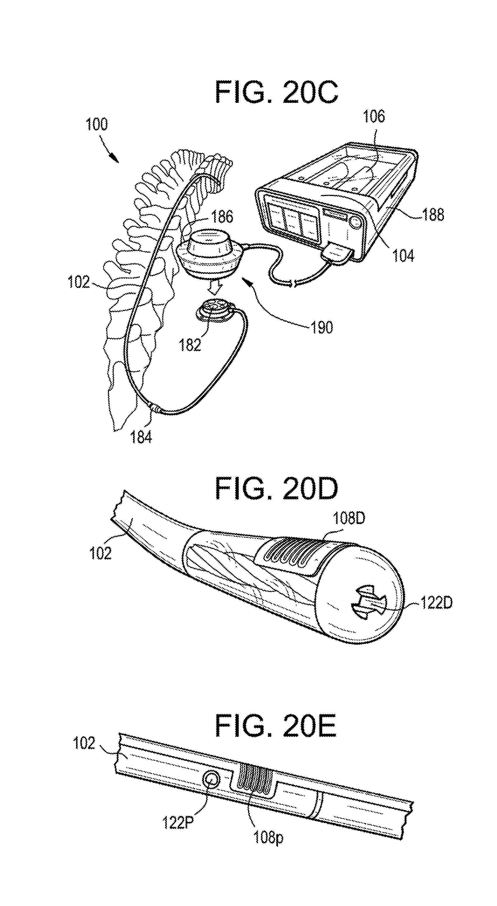
D00013

D00014

D00015

D00016
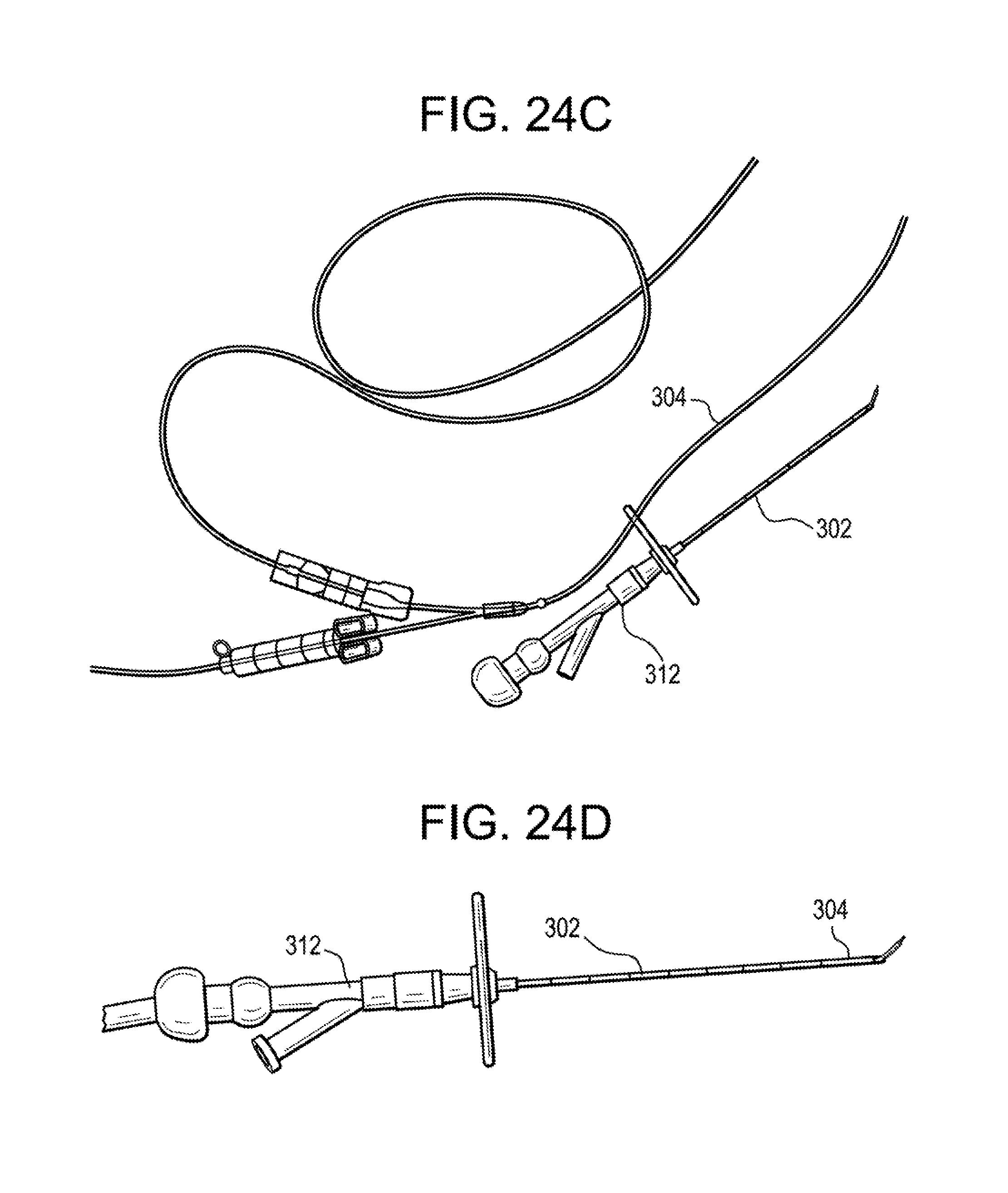
D00017

D00018

D00019

D00020
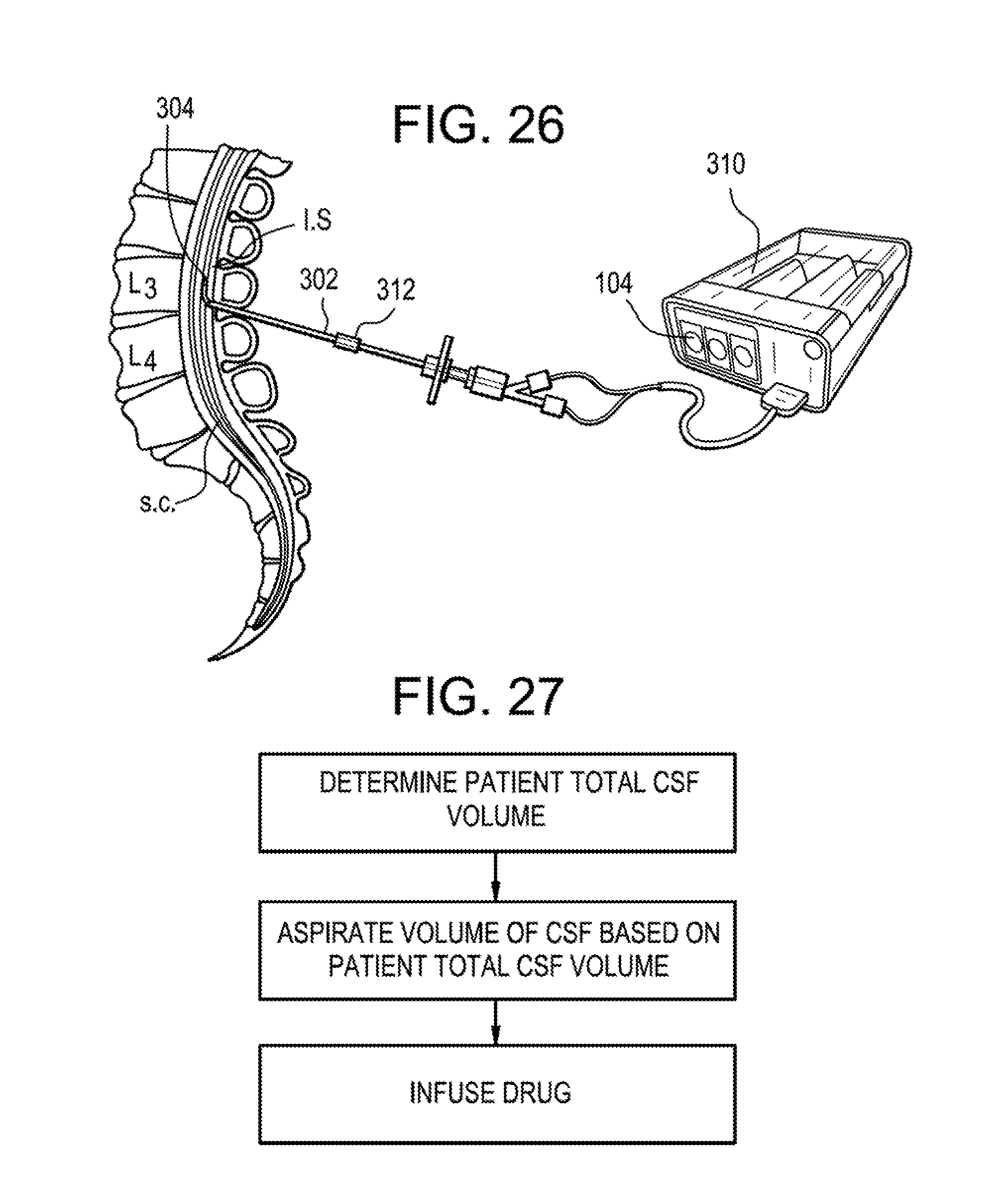
D00021

D00022

D00023

D00024
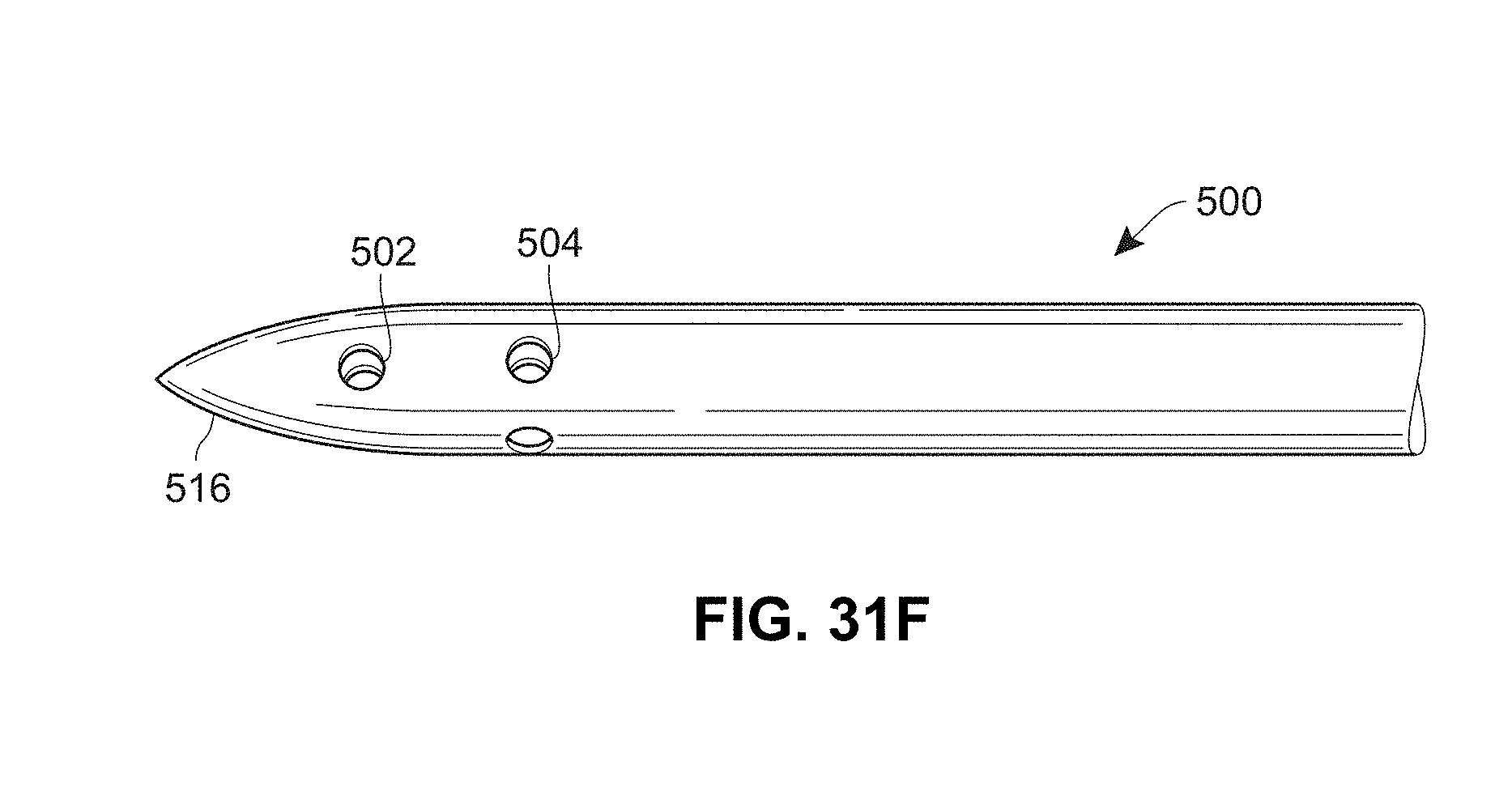
D00025
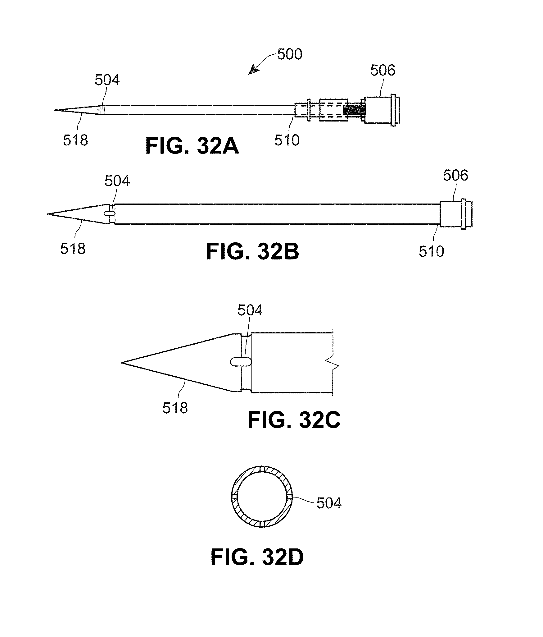
D00026

D00027

D00028
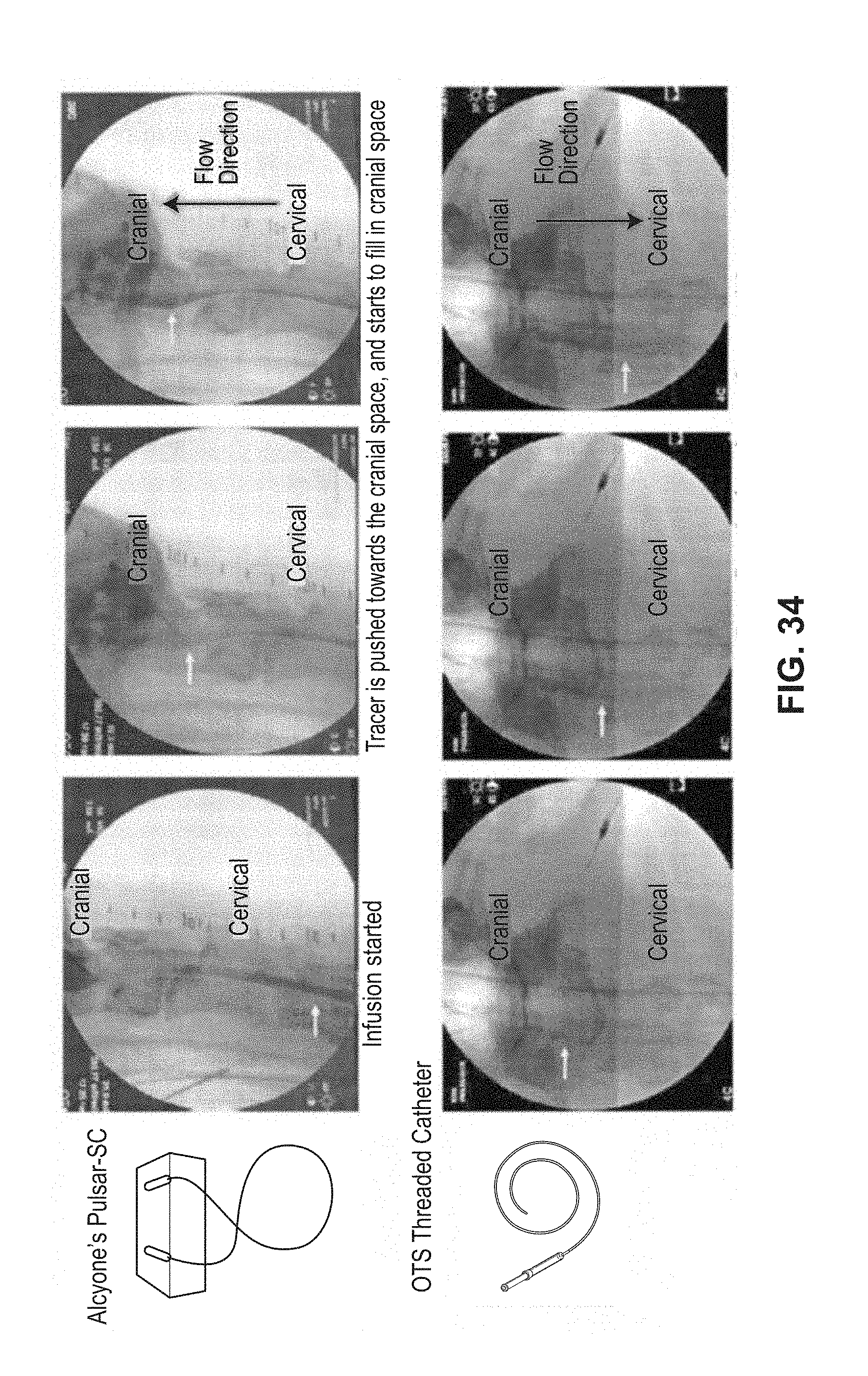
D00029
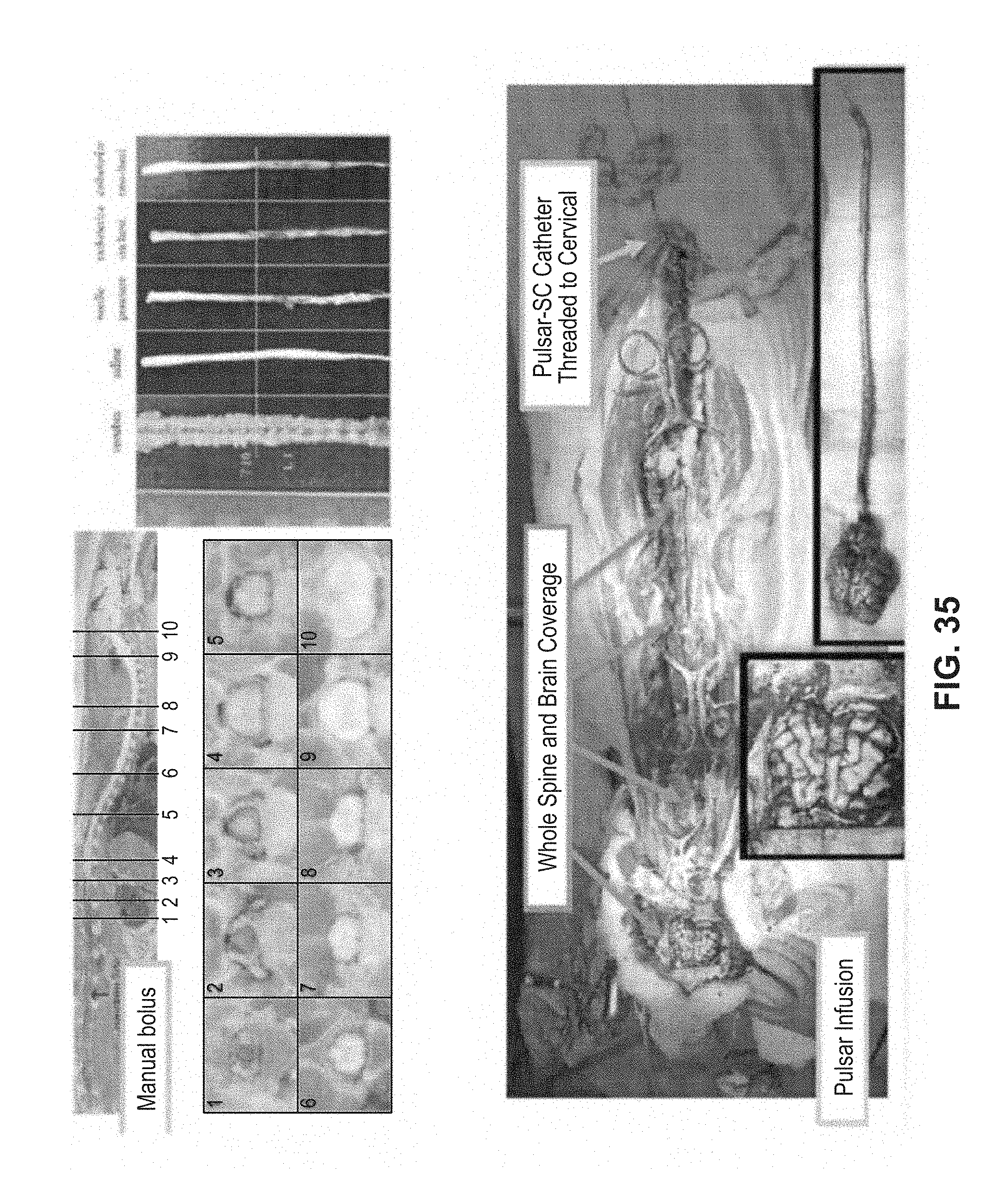
D00030

D00031
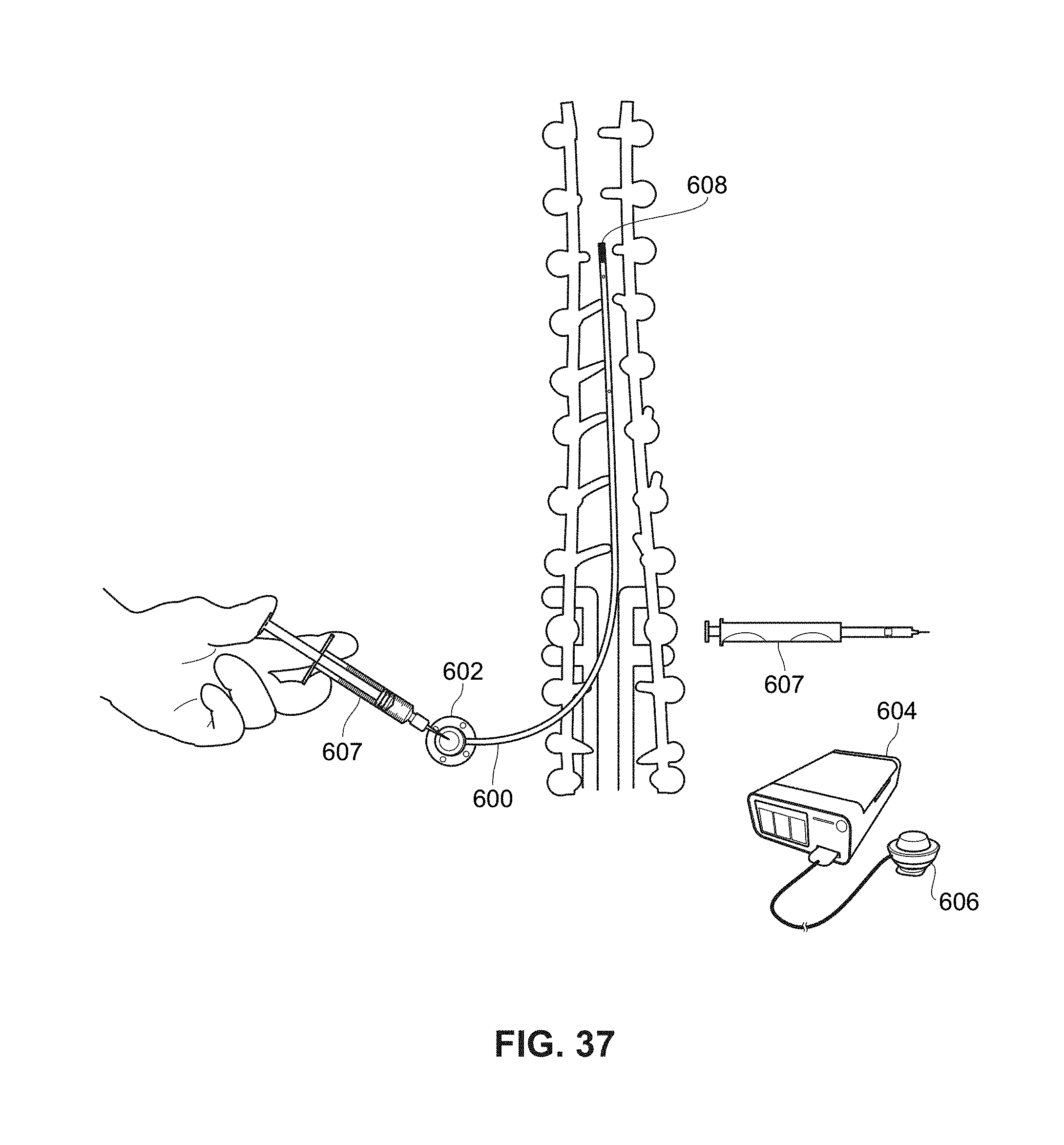
D00032
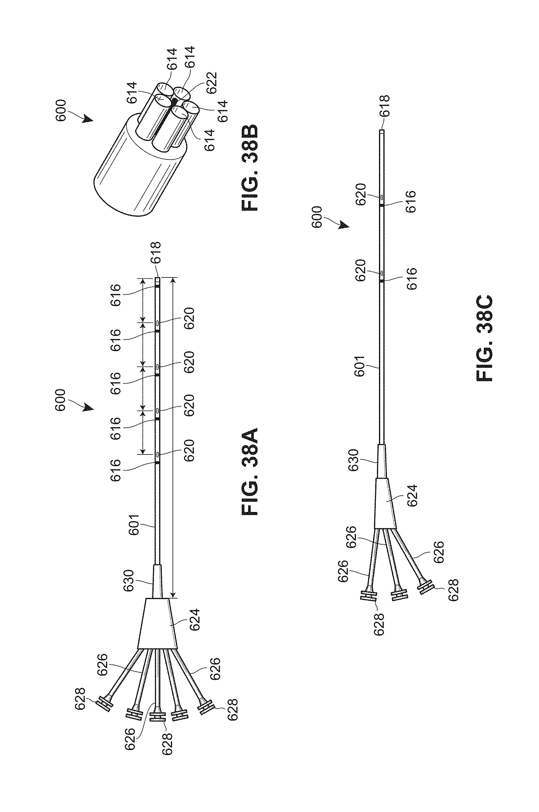
D00033

D00034

D00035
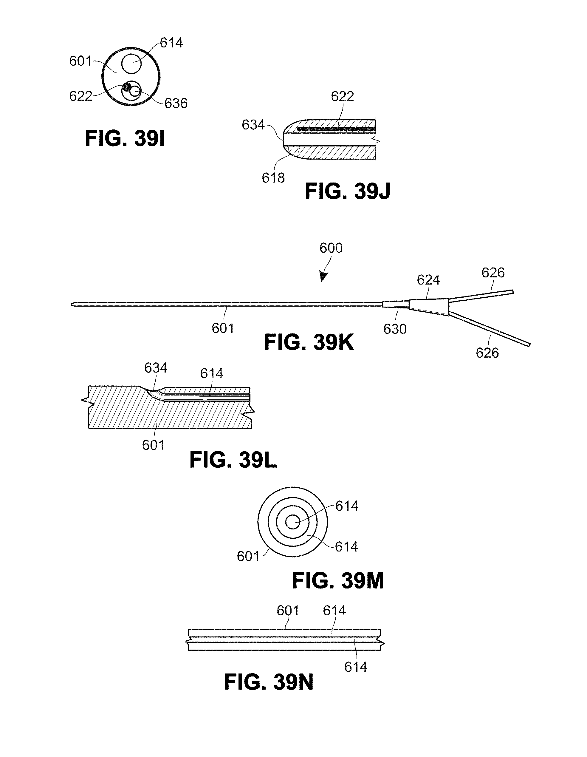
D00036
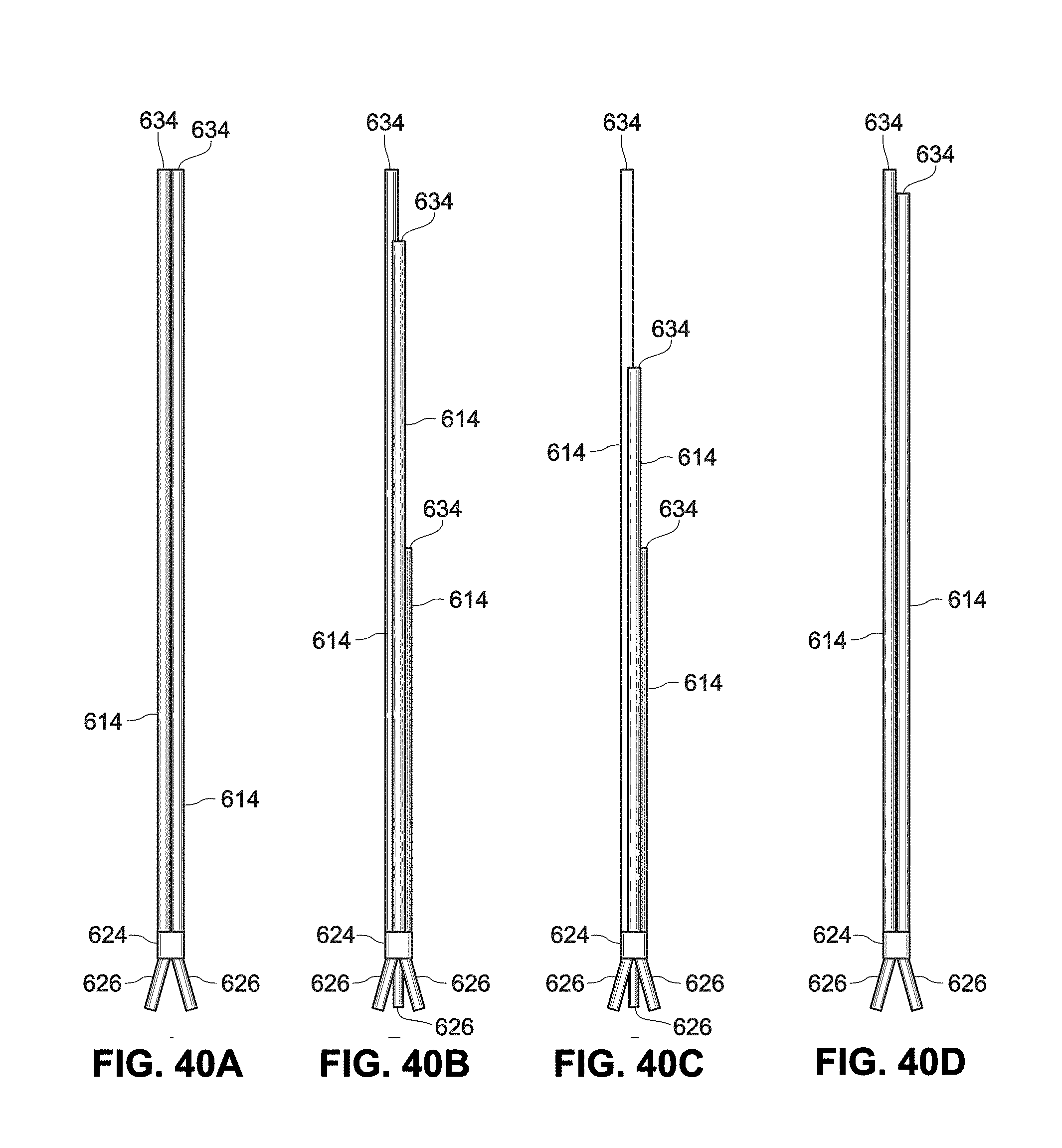
D00037

D00038
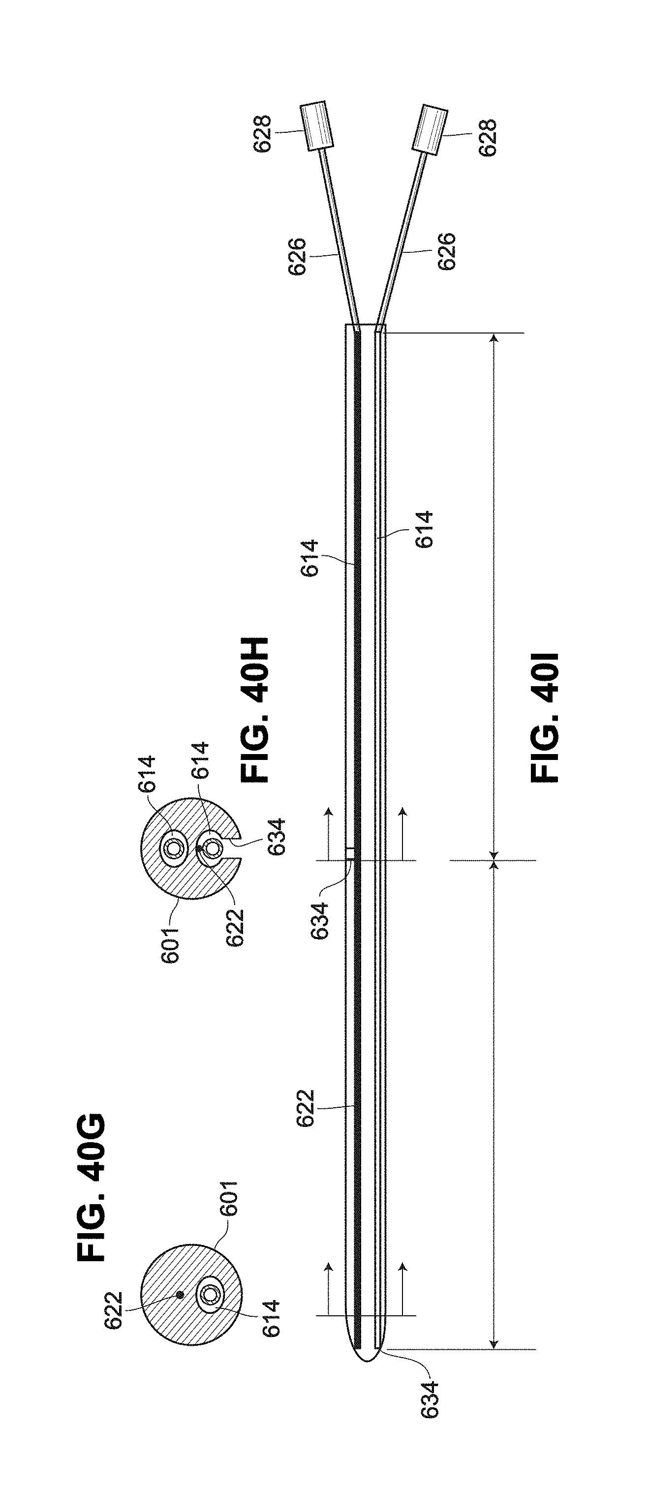
D00039

D00040
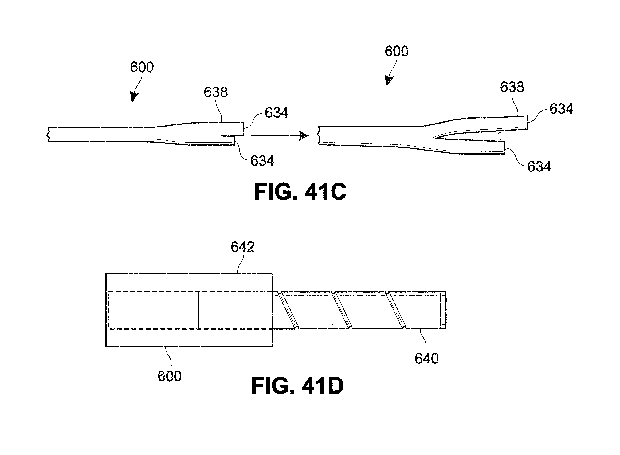
D00041

D00042
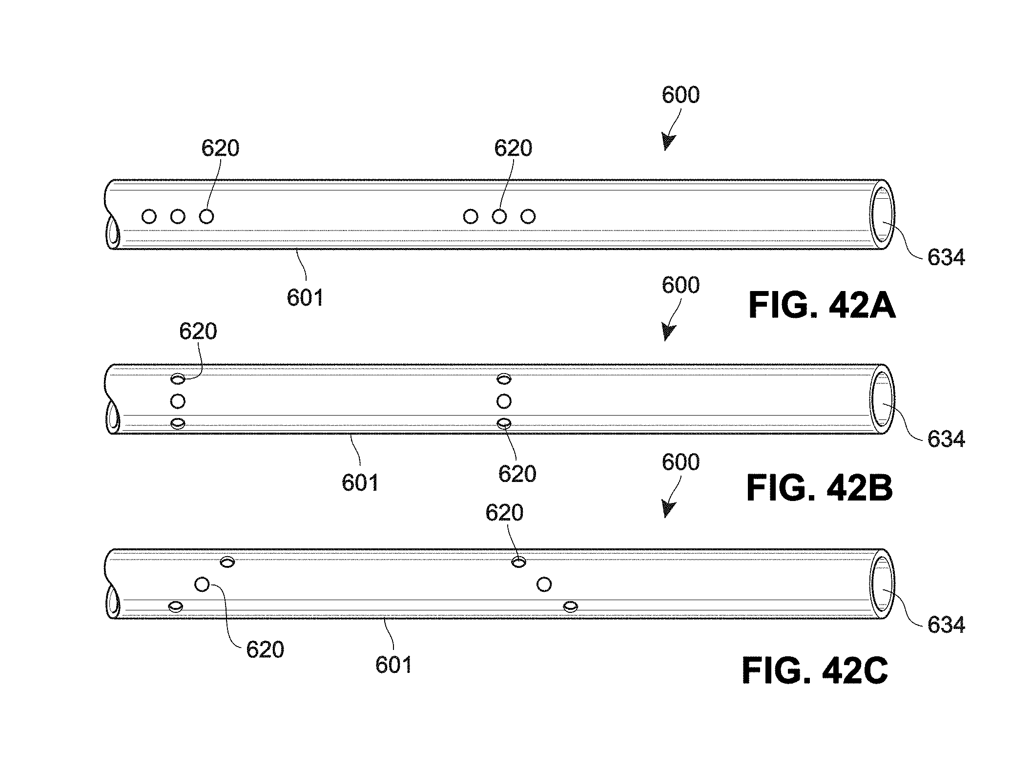
D00043
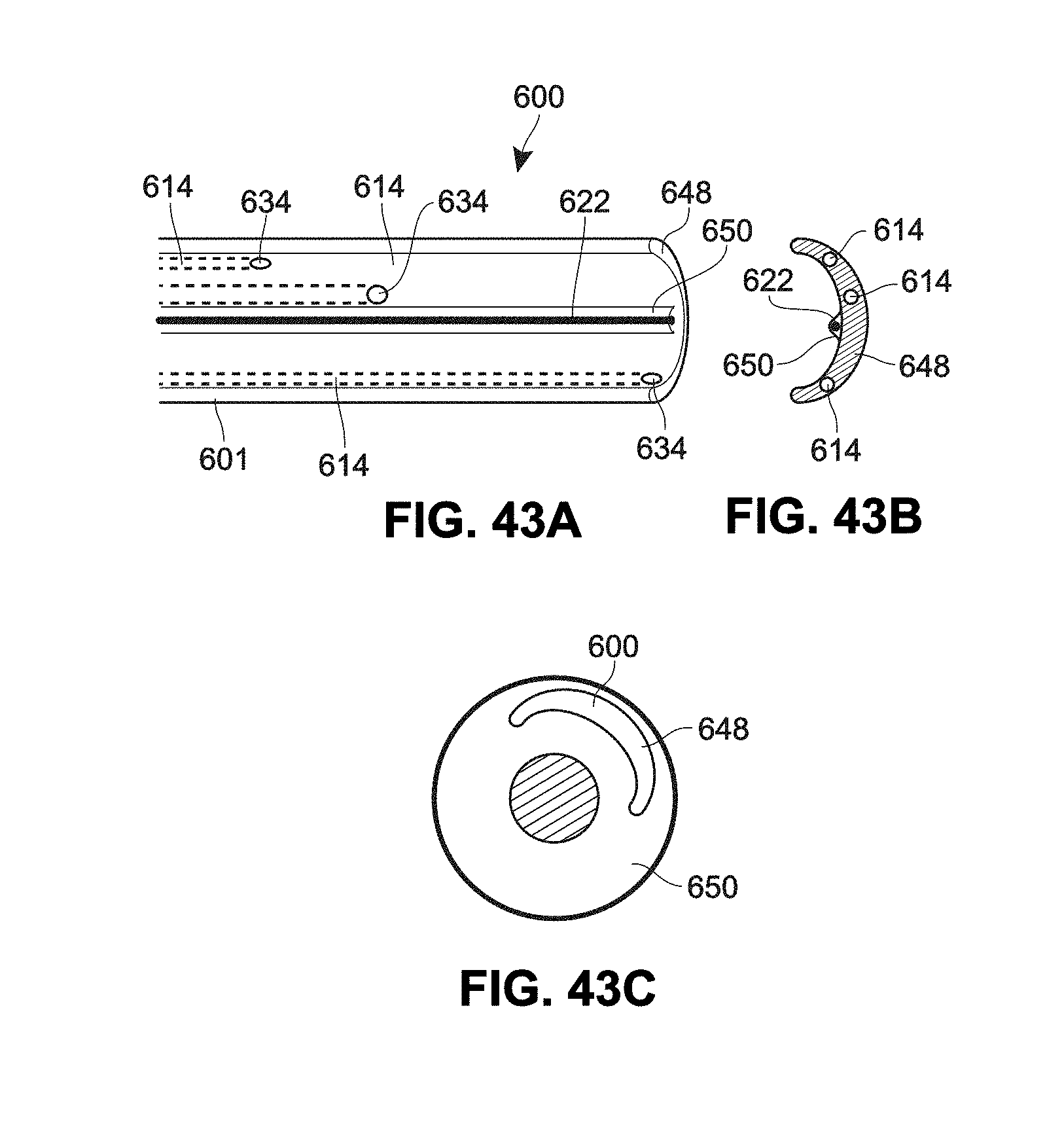
D00044
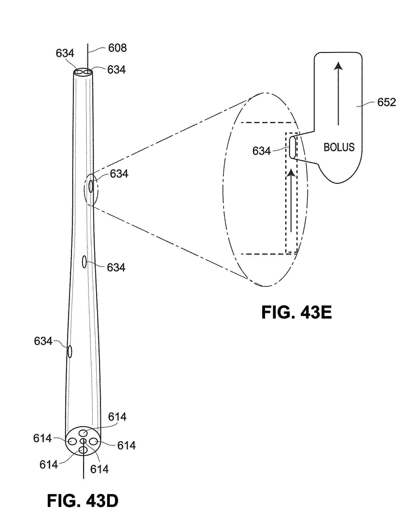
D00045

D00046
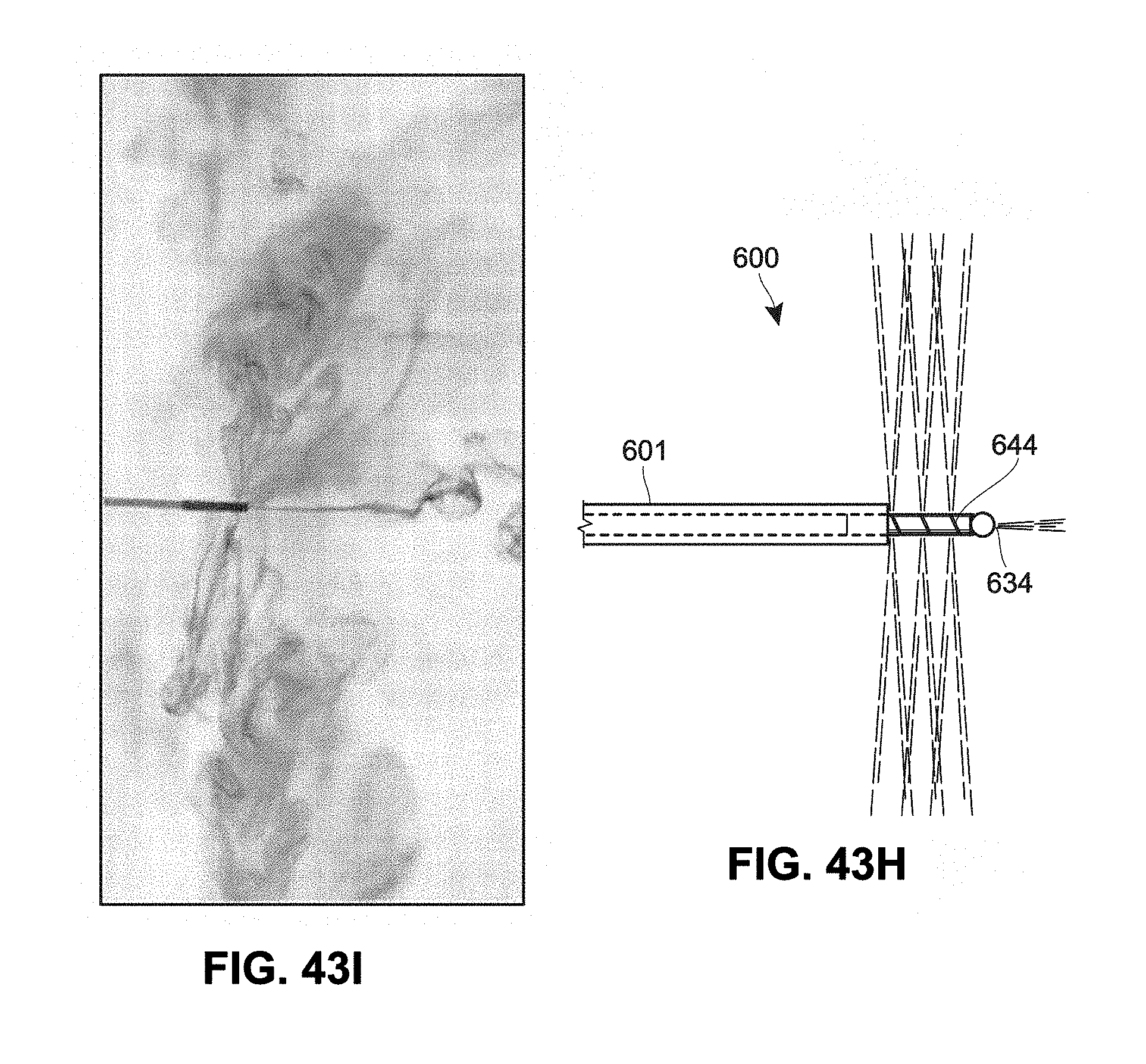
D00047
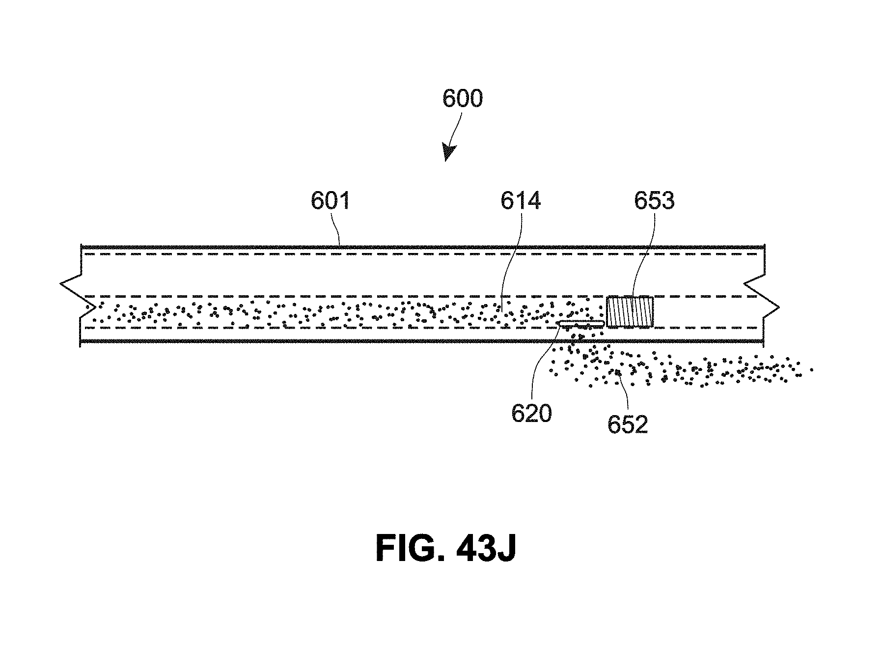
D00048
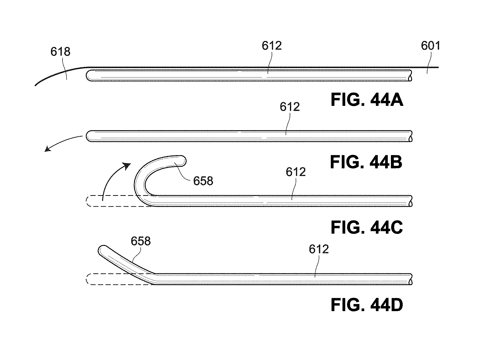
D00049
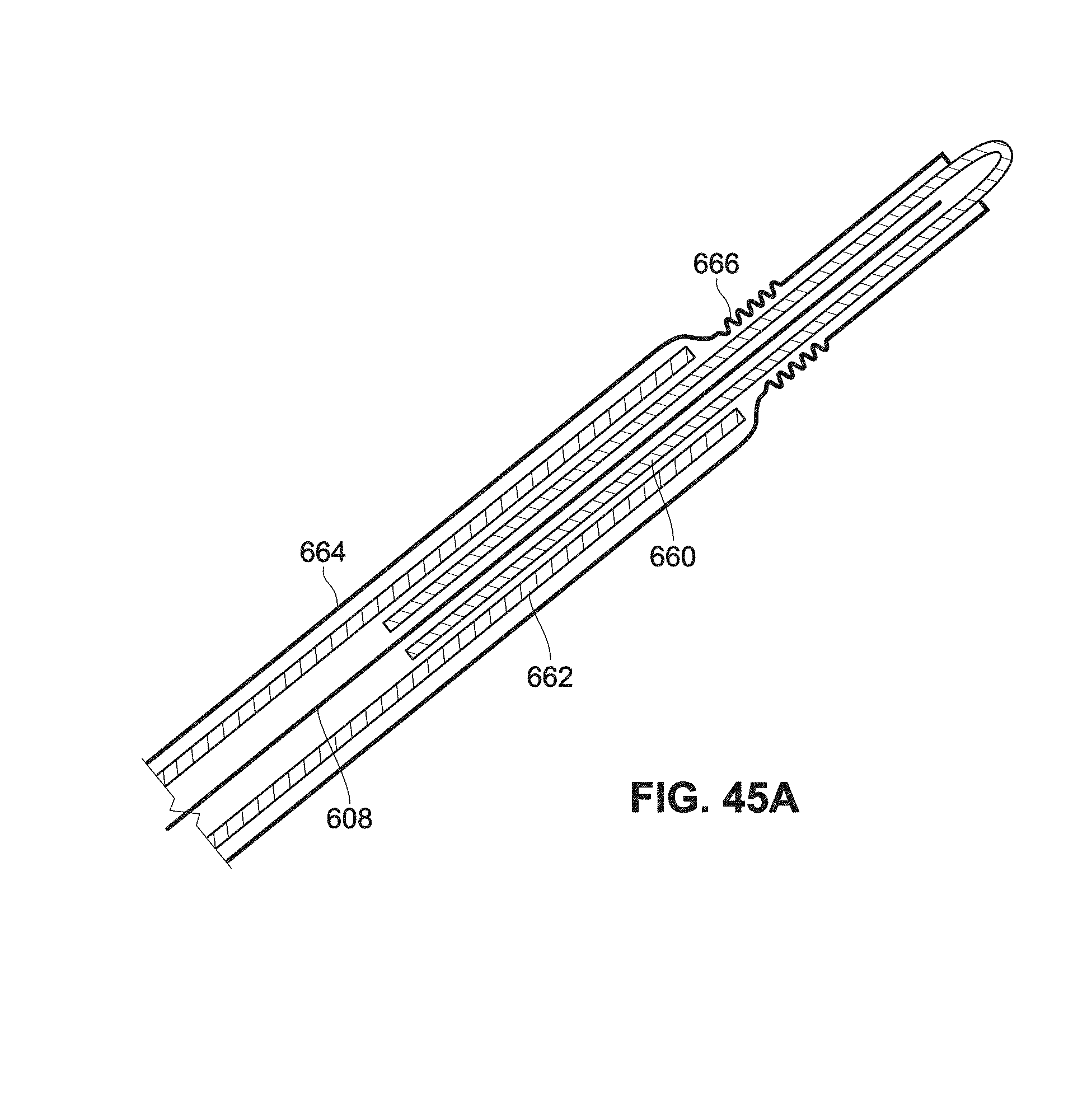
D00050

D00051

D00052

D00053
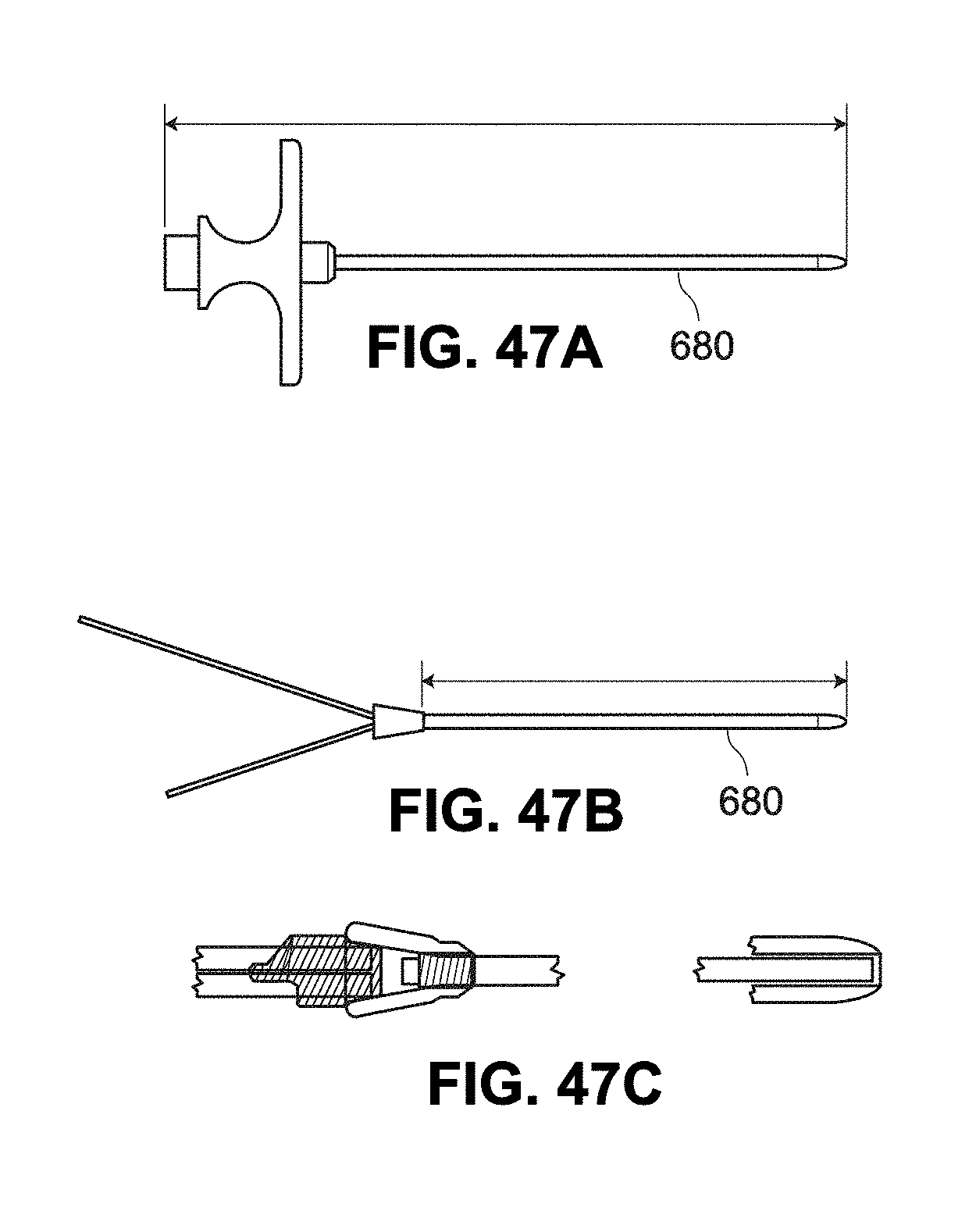
D00054

D00055
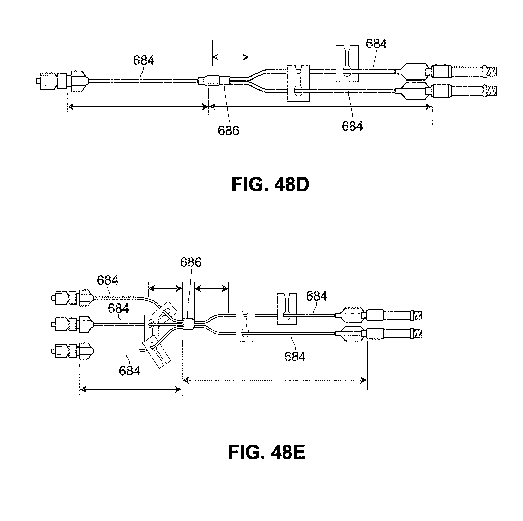
D00056

D00057

D00058

D00059
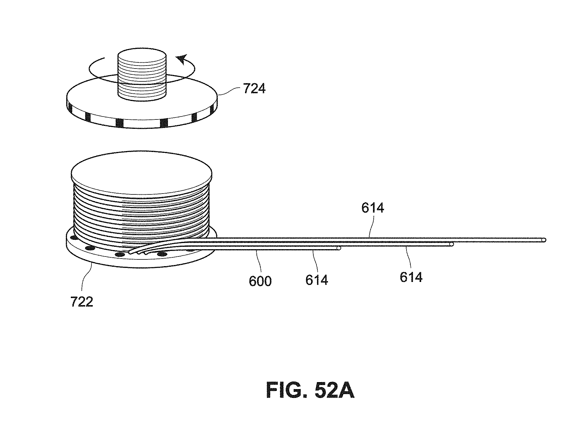
D00060

D00061
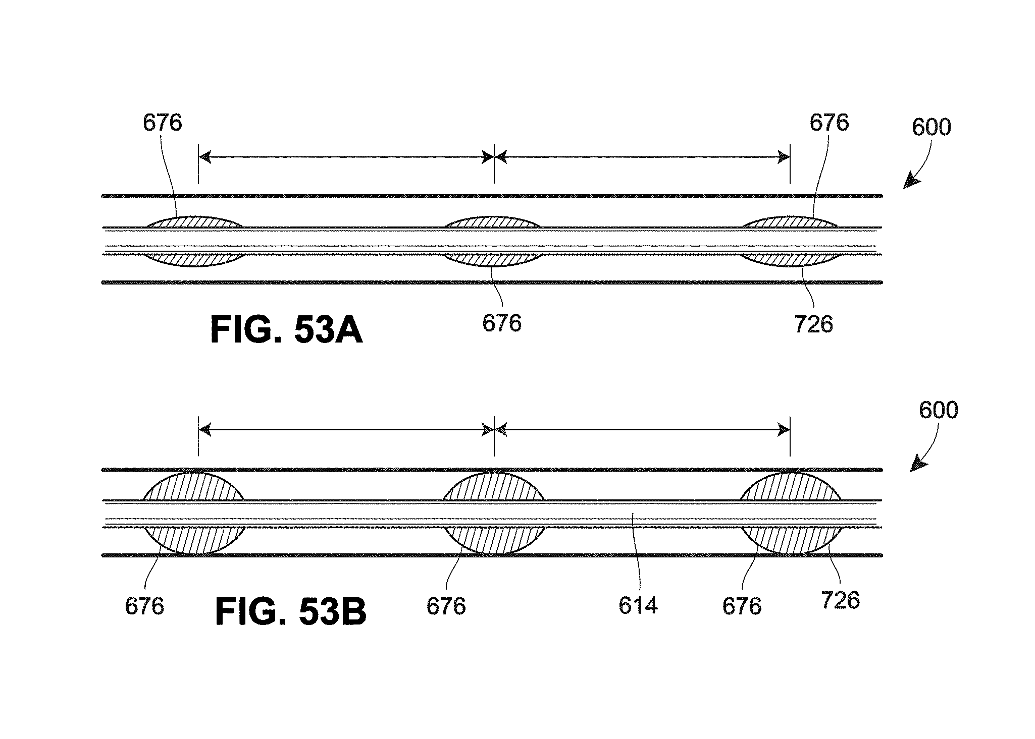
D00062
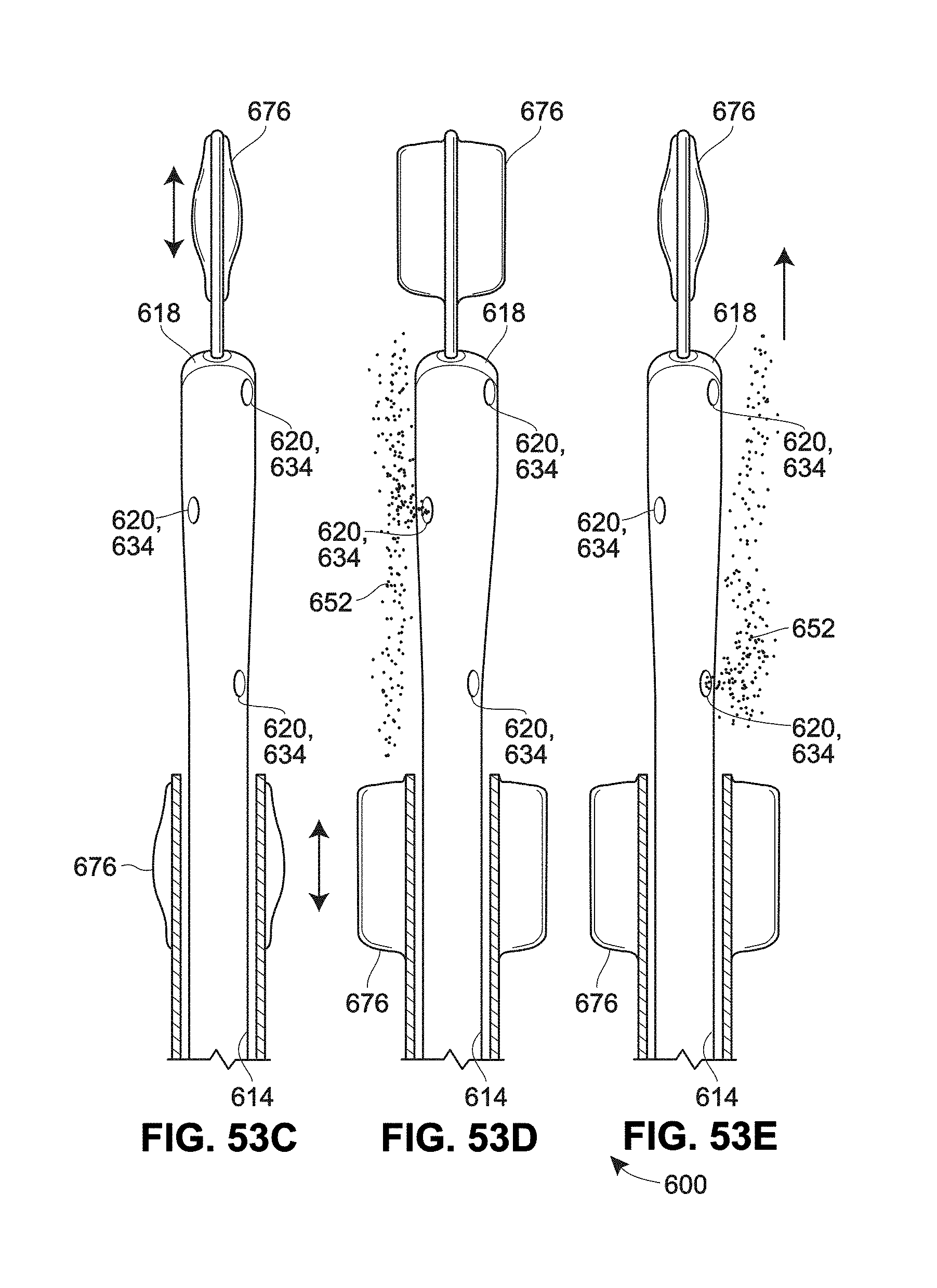
D00063
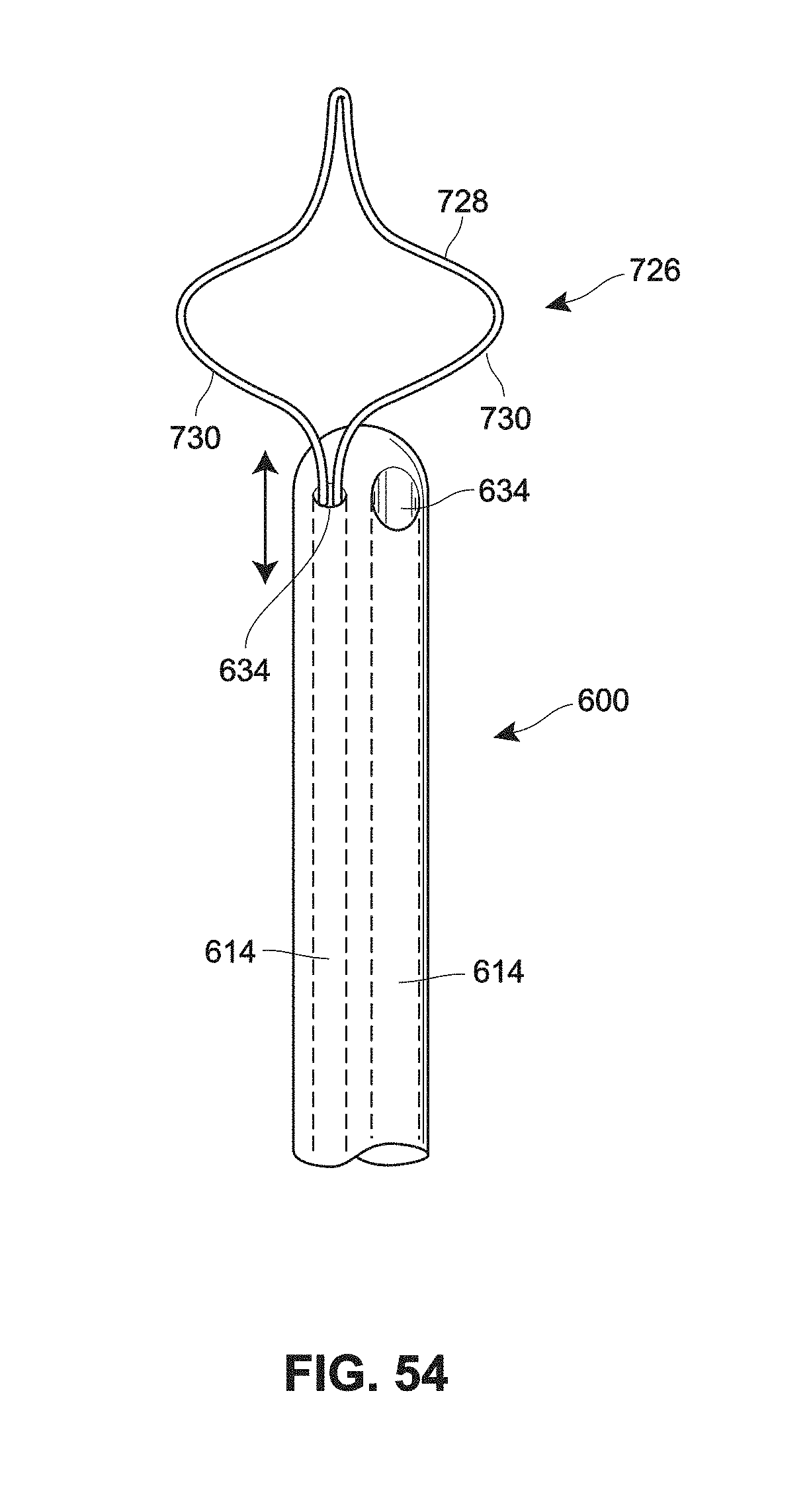
D00064

D00065
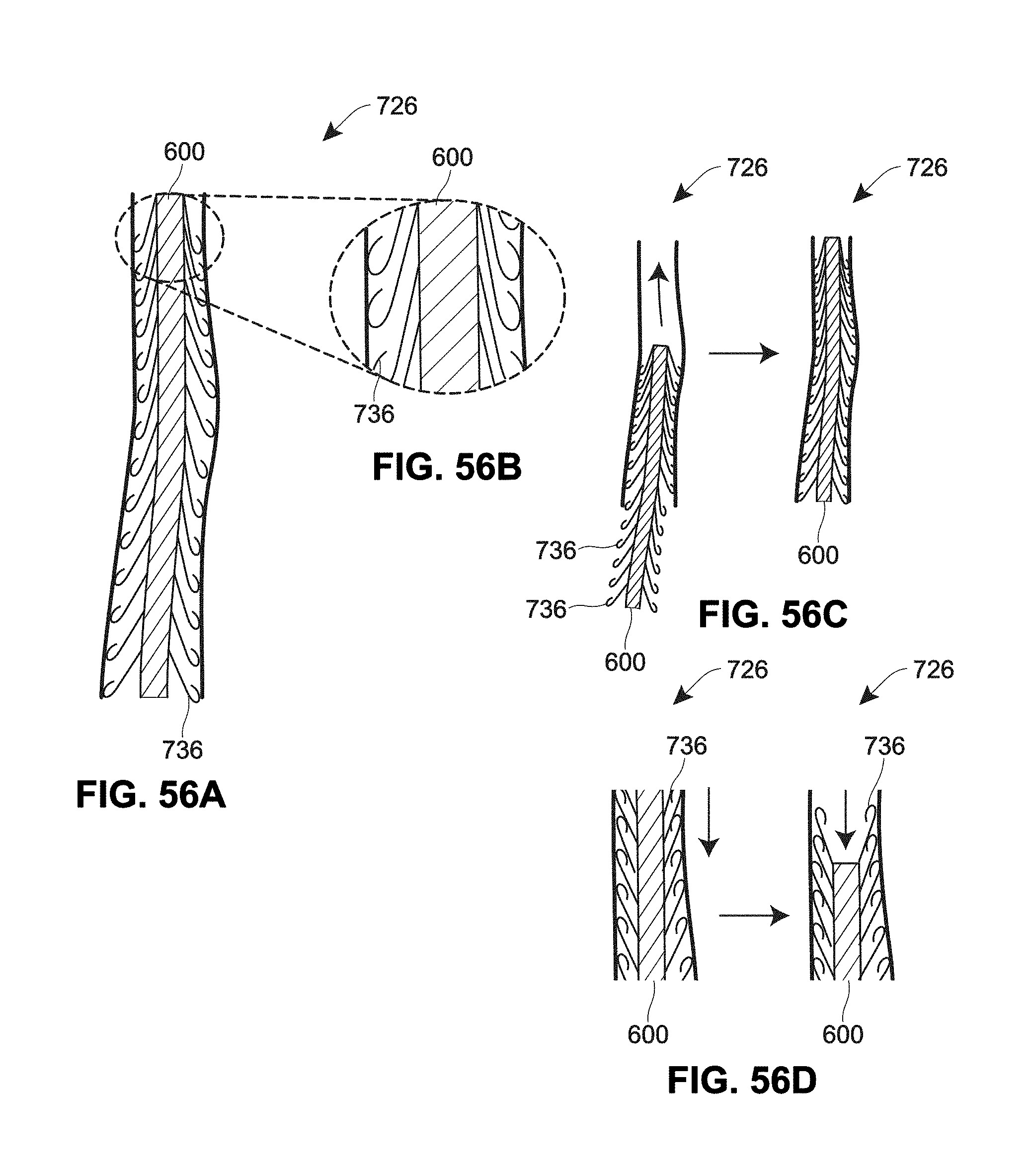
D00066

D00067
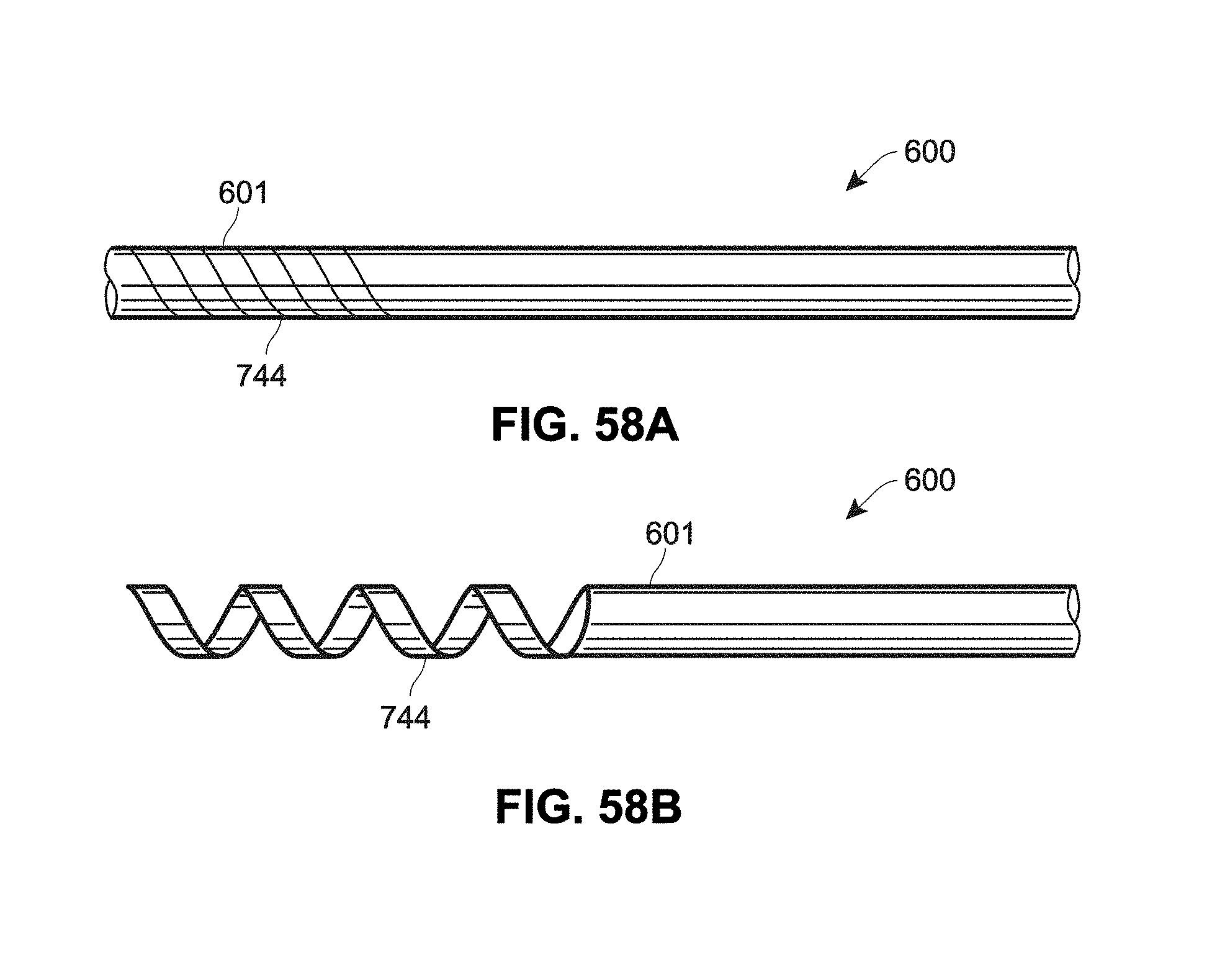
D00068
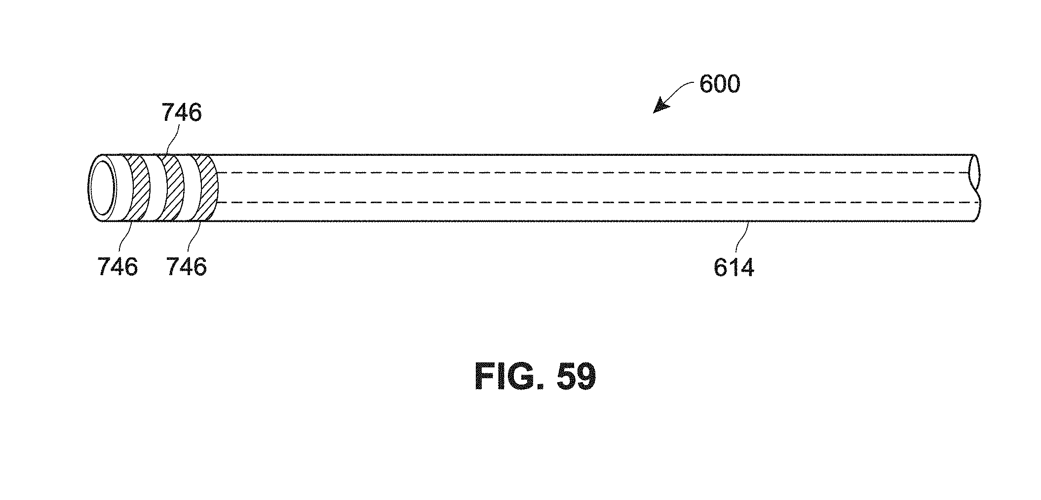
D00069

D00070

D00071
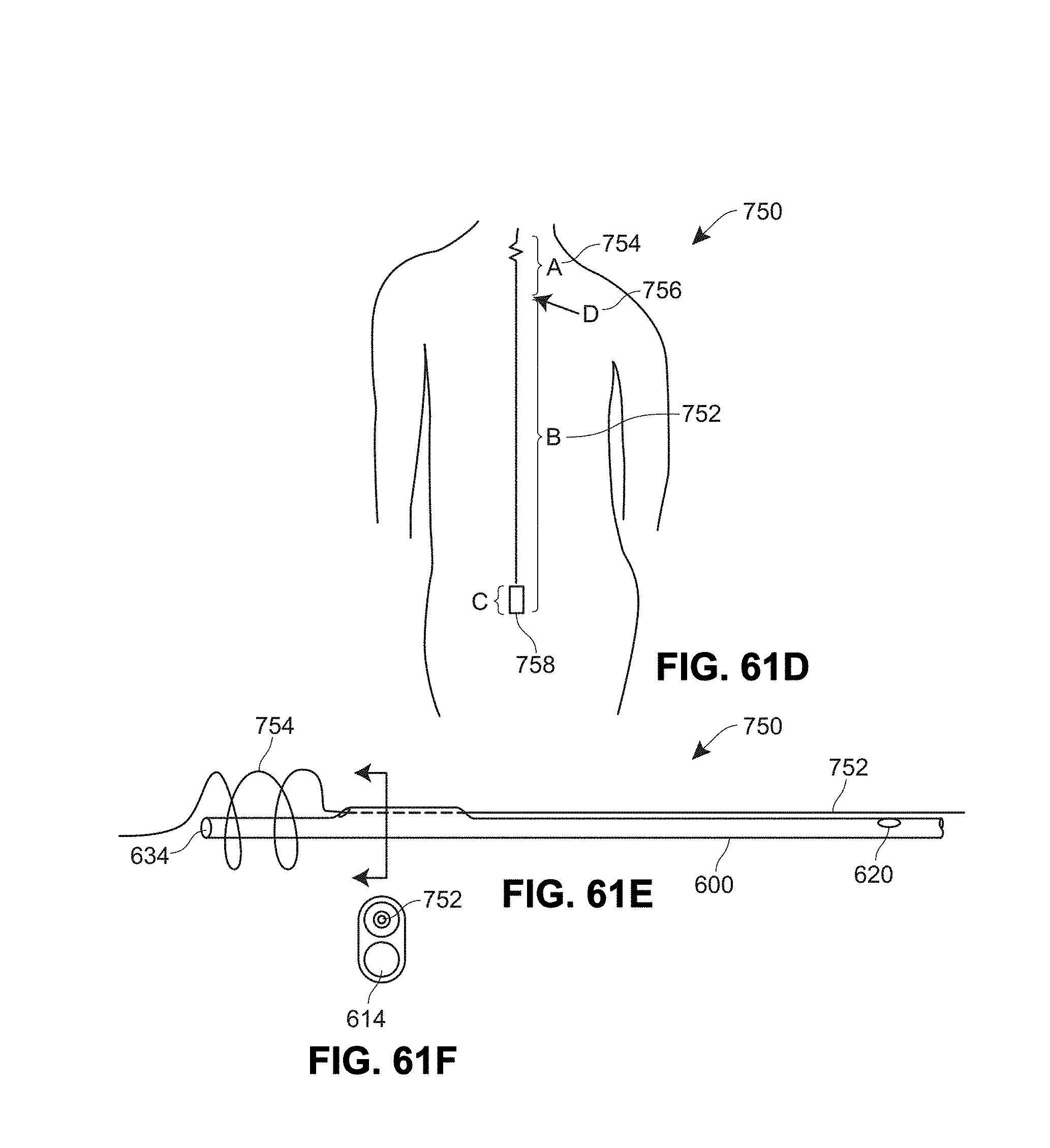
D00072

D00073
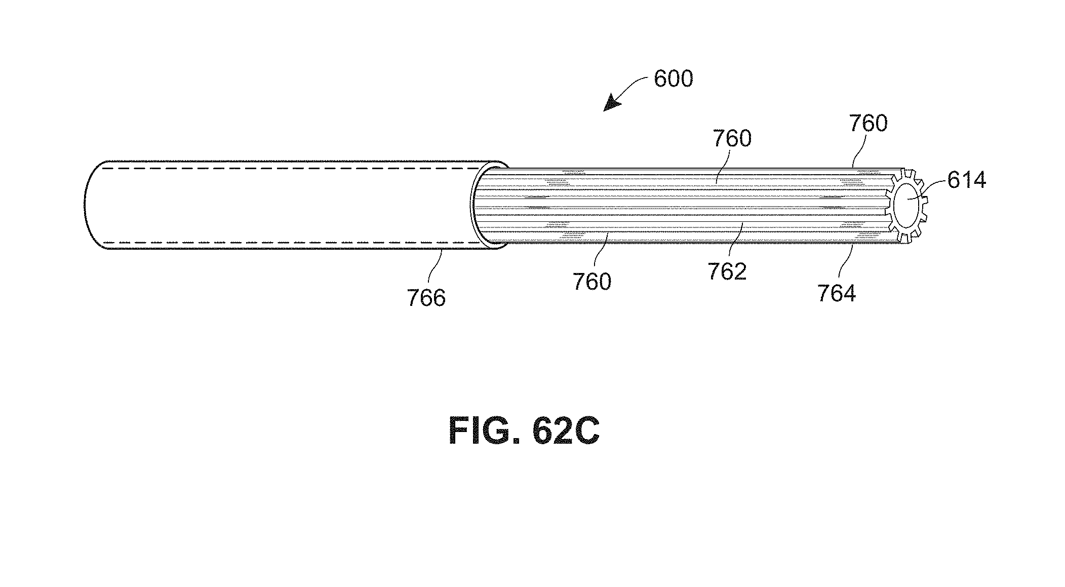
XML
uspto.report is an independent third-party trademark research tool that is not affiliated, endorsed, or sponsored by the United States Patent and Trademark Office (USPTO) or any other governmental organization. The information provided by uspto.report is based on publicly available data at the time of writing and is intended for informational purposes only.
While we strive to provide accurate and up-to-date information, we do not guarantee the accuracy, completeness, reliability, or suitability of the information displayed on this site. The use of this site is at your own risk. Any reliance you place on such information is therefore strictly at your own risk.
All official trademark data, including owner information, should be verified by visiting the official USPTO website at www.uspto.gov. This site is not intended to replace professional legal advice and should not be used as a substitute for consulting with a legal professional who is knowledgeable about trademark law.