Mobile Device Case For Receiving Wireless Signals
DiLella; Mark Stephen
U.S. patent application number 15/820197 was filed with the patent office on 2019-05-23 for mobile device case for receiving wireless signals. The applicant listed for this patent is MOPHIE INC.. Invention is credited to Mark Stephen DiLella.
| Application Number | 20190158136 15/820197 |
| Document ID | / |
| Family ID | 66534656 |
| Filed Date | 2019-05-23 |


| United States Patent Application | 20190158136 |
| Kind Code | A1 |
| DiLella; Mark Stephen | May 23, 2019 |
MOBILE DEVICE CASE FOR RECEIVING WIRELESS SIGNALS
Abstract
A wireless case for use with a mobile electronic device can include a back wall, a top wall, a bottom wall, a right side wall, a left side wall. The case can include a wireless receiver configured to receive wireless signals. The case can further include a device interface that can be electrically coupled to the wireless receiver. The device interface can move between an engaged position and a disengaged position. In the engaged position, the device interface can be configured to engage a corresponding interface on the mobile electronic device to deliver the electrical signals from the wireless receiver to the mobile electronic device. In the disengaged position the device interface can be configured to disengage from the corresponding interface on the mobile electronic device to facilitate insertion of the mobile electronic device into the case or removal of the mobile electronic device from the case.
| Inventors: | DiLella; Mark Stephen; (Irvine, CA) | ||||||||||
| Applicant: |
|
||||||||||
|---|---|---|---|---|---|---|---|---|---|---|---|
| Family ID: | 66534656 | ||||||||||
| Appl. No.: | 15/820197 | ||||||||||
| Filed: | November 21, 2017 |
| Current U.S. Class: | 1/1 |
| Current CPC Class: | H04B 1/3888 20130101; H02J 7/025 20130101; H02J 7/00034 20200101; H02J 50/10 20160201; H02J 7/0047 20130101; H02J 7/0044 20130101; H02J 50/90 20160201; H02J 7/00 20130101 |
| International Class: | H04B 1/3888 20060101 H04B001/3888; H02J 7/02 20060101 H02J007/02 |
Claims
1. A wireless case for use with a mobile electronic device, the wireless case comprising: a back wall configured to extend across at least a portion of a back of a mobile electronic device; a top wall configured to extend along at least a portion of a top of the mobile electronic device; a bottom wall configured to extend along at least a portion of a bottom of the mobile electronic device; a right side wall configured to extend along at least a portion of a right side of the mobile electronic device; a left side wall configured to extend along at least a portion of a left side of the mobile electronic device; a front opening configured such that a display of the mobile electronic device is visible through the front opening; a wireless receiver configured to extend across at least a portion of the back wall such that the wireless receiver is configured to be behind the back of the mobile electronic device, the wireless receiver configured to receive wirelessly signals; and a device interface electrically coupled to the wireless receiver, wherein the device interface is movable relative to at least the bottom wall between an engaged position and a disengaged position, wherein in the engaged position the device interface is configured to engage a corresponding interface on the mobile electronic device to deliver the electrical signals from the wireless receiver to the mobile electronic device, and wherein in the disengaged position the device interface is configured to disengage from the corresponding interface on the mobile electronic device to facilitate insertion of the mobile electronic device into the case or removal of the mobile electronic device from the case.
2. The wireless case of claim 1, wherein the wireless receiver is configured to receive a wireless charging signal such that the device interface delivers electrical power to the mobile electronic device based on the wireless charging signal.
3. The wireless case of claim 1, wherein the wireless receiver comprises a wireless charging receiver coil.
4. The wireless case of claim 1, wherein the wireless receiver moves with the device interface as the device interface moves between the engaged position and the disengaged position.
5. The wireless case of claim 1, wherein the device interface slides in a direction away from the top wall to move to the disengaged position, and wherein the device interface slides in a direction towards the top wall to move to the engaged position.
6. The wireless case of claim 1, further comprising an opening in the bottom wall, wherein the device interface passes through the opening in the bottom wall to move from the engaged position to the disengaged position.
7. The wireless case of claim 1, wherein the case comprises an interior area between the back wall, the front opening, the top wall, the bottom wall, the right side wall, and the left side wall, and wherein the device interface is positioned outside the interior area when in the disengaged position.
8. The wireless case of claim 1, wherein the wireless receiver and the device interface are coupled by a flexible connector.
9. The wireless case of claim 1, wherein the device interface in the disengaged position is movable to expose the corresponding interface of the mobile electronic device.
10. The wireless case of claim 1, wherein the case provides access for an external interface to engage the corresponding interface of the mobile electronic device when the device interface is in the disengaged position.
11. The wireless case of claim 1, wherein one or more of the back wall, the top wall, the bottom wall, the right side wall, and the left side wall is flexible such that the mobile electronic device can pass through the front opening and be securely disposed within the wireless case.
12. The wireless case of claim 1, wherein the wireless case is configured to house a smartphone, and wherein the wireless case has an external shape that generally corresponds to an external shape of the smartphone.
13. The wireless case of claim 1, comprising an opening on a back side of the case that provides access to an actuator for moving the device interface from the engaged position to the disengaged position.
14. The wireless case of claim 13, wherein the actuator comprises a grip configured to be manipulated by a user's finger.
15. The wireless case of claim 1, wherein the wireless receiver is removable and reinsertable.
16. The wireless case of claim 1, wherein the device interface is removable and reinsertable.
17. The wireless case of claim 1, further comprising one or more guides that define a direction of motion and/or range of motion for the device interface.
18. The wireless case of claim 1, wherein the back wall comprises one or more tabs and wherein a housing containing the wireless receiver comprises one or more slots that allow the one or more tabs to pass therethrough.
19. The wireless case of claim 1, wherein a housing contains the wireless receiver, wherein the back wall comprises a recess for receiving the wireless receiver, wherein the recess is larger than the housing to permit the wireless receiver and housing to move with the device interface.
20. A system for transferring wireless signals to or from a mobile electronic device, the system comprising: a case configured to at least partially enclose the mobile electronic device; a wireless antenna external to the case so that the wireless antenna is between a back of the mobile electronic device and the case when the mobile electronic device is in the case; and a device interface electrically coupled to the wireless antenna and configured to engage a corresponding interface on the mobile electronic device; wherein one or both of the device interface and the wireless antenna is movable relative to the case.
21. The system of claim 20, wherein the system is configured for wireless charging of a battery of the mobile electronic device.
22. The system of claim 20, wherein the wireless antenna is a wireless charging receiver coil.
23. The system of claim 20, wherein the wireless antenna is movable within the case.
24. The system of claim 20, wherein the wireless antenna is disposed in a housing, wherein the case comprises a recess configured to receive the wireless antenna, and wherein the recess is larger than the housing so that the housing and wireless antenna can move within the recess.
25. The system of claim 20, wherein the device interface is movable between an engaged position and a disengaged position.
26. The system of claim 25, wherein the wireless antenna moves with the device interface between the engaged position and the disengaged position.
27. The system of claim 25, wherein the device interface moves through an opening in the case when moving from the engaged position to the disengaged position.
28. The system of claim 25, wherein at least a majority of the device interface is positioned outside of the case when in the disengaged position.
29. The system of claim 20, wherein the wireless antenna and the device interface are coupled by a flexible connector.
30. The system of claim 20, wherein the device interface is movable to expose the corresponding interface on the mobile electronic device through the case, such that an external interface can engage the corresponding interface on the mobile electronic device.
31. The system of claim 20, wherein at least a portion of the case is flexible.
32. The system of claim 20, wherein the case is configured to house a smartphone, and wherein the case has an external shape that generally corresponds to an external shape of the smartphone.
33. The system of claim 20, wherein an opening through the case provides access to an actuator configured to move the device interface.
34. The system of claim 33, wherein the actuator is configured to be engaged by a user's finger to pull the device interface out of the corresponding interface on the mobile electronic device.
35. The wireless case of claim 1, wherein the wireless receiver is positioned forward of the back wall so that the wireless receiver is between the back wall and the back of the mobile electronic device when the mobile electronic device is in the case.
36. The system of claim 20, wherein one or both of the device interface and the wireless antenna is movable relative to a bottom wall of the case that is configured to extend along a bottom portion of the mobile electronic device.
Description
BACKGROUND
Field of the Invention
[0001] This disclosure relates to cases capable of receiving wireless signals for use with mobile electronic devices.
Description of the Related Art
[0002] Although various methods of providing mobile electronic devices with wireless signals are available, there remains a need for improved cases capable of receiving wireless signals for use with mobile electronic devices.
SUMMARY OF CERTAIN EMBODIMENTS
[0003] Certain embodiments are summarized below by way of example and are not intended to limit the scope of the claims.
[0004] Various embodiments disclosed herein can relate to a wireless case for use with a mobile electronic device. The wireless case can include a back wall configured to extend across at least a portion of a back of the mobile electronic device, a top wall configured to extend along at least a portion of a top of the mobile electronic device, a bottom wall configured to extend along at least a portion of a bottom of the mobile electronic device, a right side wall configured to extend along at least a portion of a right side of the mobile electronic device, a left side wall configured to extend along at least a portion of a left side of the mobile electronic device, and a front opening configured such that a display of the mobile electronic device is visible through the front opening.
[0005] The case can include a wireless receiver configured to extend across at least a portion of the back wall such that the wireless receiver can be configured to be behind the back of the mobile electronic device. The wireless receiver can be configured to receive wireless signals. The case can include a device interface that can be electrically coupled to the wireless receiver. The device interface can move between an engaged position and a disengaged position. In the engaged position, the device interface can be configured to engage a corresponding interface on the mobile electronic device to deliver the electrical signals from the wireless receiver to the mobile electronic device. In the disengaged position the device interface can be configured to disengage from the corresponding interface on the mobile electronic device to facilitate insertion of the mobile electronic device into the case or removal of the mobile electronic device from the case.
[0006] The wireless receiver can be configured to receive a wireless charging signal, such that the device interface can deliver electrical power to the mobile electronic device based on the wireless charging signal. The wireless receiver can comprises a wireless charging receiver coil. The wireless receiver can move with the device interface as the device interface moves between the engaged position and the disengaged position. The device interface can slide in a direction away from the top wall to move to the disengaged position, and can slide in a direction towards the top wall to move to the engaged position. The wireless case can include an opening in the bottom wall. The device interface can pass through the opening in the bottom wall to move from the engaged position to the disengaged position. The case can define an interior area between the back wall, the front opening, the top wall, the bottom wall, the right side wall, and the left side wall. The device interface can be positioned outside the interior area when in the disengaged position. The wireless receiver and the device interface can be coupled by a flexible connector. When the device interface is in the disengaged position, it can be movable to expose the corresponding interface of the mobile electronic device. The case can provide access for an external interface to engage the corresponding interface of the mobile electronic device when the device interface is in the disengaged position.
[0007] One or more of the back wall, the top wall, the bottom wall, the right side wall, and the left side wall can be flexible such that the mobile electronic device can pass through the front opening and be securely disposed within the wireless case. The wireless case can house a smartphone and can have an external shape that generally corresponds to an external shape of the smartphone. The wireless case can include an opening on a back side of the case that can provide access to an actuator for moving the device interface from the engaged position to the disengaged position. The actuator can include a grip configured to be manipulated by a user's finger. The wireless receiver and the device interface can be removed from the case. The wireless case can further comprise one or more guides that define a direction of motion and/or range of motion for the device interface. The back wall can comprise one or more tabs. A housing can contain the wireless receiver and can comprise one or more slots that allow the one or more tabs to pass therethrough. The back wall can include a recess for receiving the wireless receiver, wherein the recess can be larger than the housing to permit the wireless receiver and housing to move with the device interface.
[0008] Various embodiments disclosed herein can relate to a system for transferring wireless signals to or from a mobile electronic device. The system can include a case configured to at least partially enclose the mobile electronic device, a wireless antenna, and a device interface electrically coupled to the wireless antenna and configured to engage a corresponding interface on the mobile electronic device. One or both of the device interface and the wireless antenna can move relative to the case.
[0009] The system can be configured for wireless charging of a battery of the mobile electronic device. The wireless antenna can be a wireless charging receiver coil and can move within the case. The wireless antenna can be disposed in a housing. The case can comprise a recess configured to receive the wireless antenna. The recess can be larger than the housing so that the housing and wireless antenna can move within the recess. The device interface can move between an engaged position and a disengaged position. The wireless antenna can move with the device interface between the engaged position and the disengaged position. The device interface can move through an opening in the case when moving from the engaged position to the disengaged position. At least a majority of the device interface can be positioned outside of the case when in the disengaged position. The wireless antenna and the device interface can be coupled by a flexible connector. The device interface can move to expose the corresponding interface on the mobile electronic device through the case, such that an external interface can engage the corresponding interface on the mobile electronic device. At least a portion of the case can be flexible. The case can be configured to house a smartphone. The case can have an external shape that generally corresponds to an external shape of the smartphone. An opening through the case can provide access to an actuator configured to move the device interface. The actuator can be configured to be engaged by a user's finger to pull the device interface out of the corresponding interface on the mobile electronic device.
BRIEF DESCRIPTION OF THE DRAWINGS
[0010] The following drawings and the associated descriptions are provided to illustrate example embodiments of the present disclosure and do not limit the scope of the claims.
[0011] FIG. 1 is a schematic view of an example embodiment of a wireless case for use with a mobile electronic device.
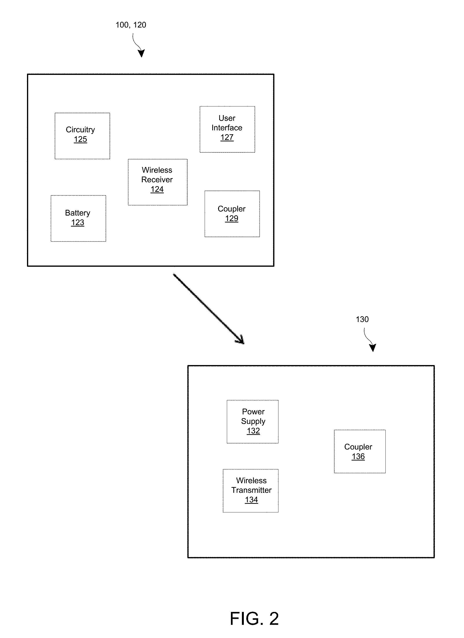
[0012] FIG. 2 is a schematic view of an example embodiment of a wireless case and a wireless charger.
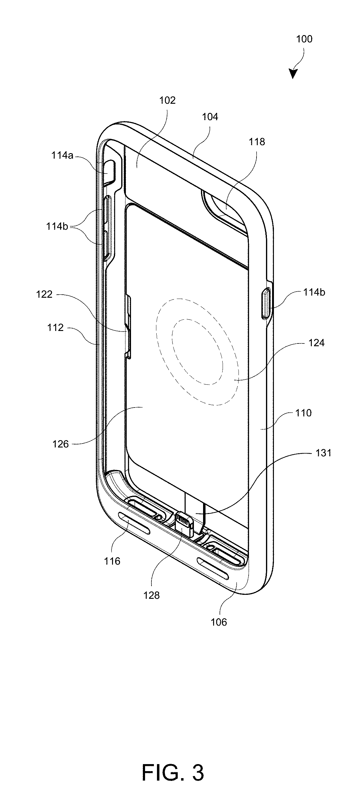
[0013] FIG. 3 is a front perspective view of an example embodiment of a wireless case with a wireless receiver in an engaged position.
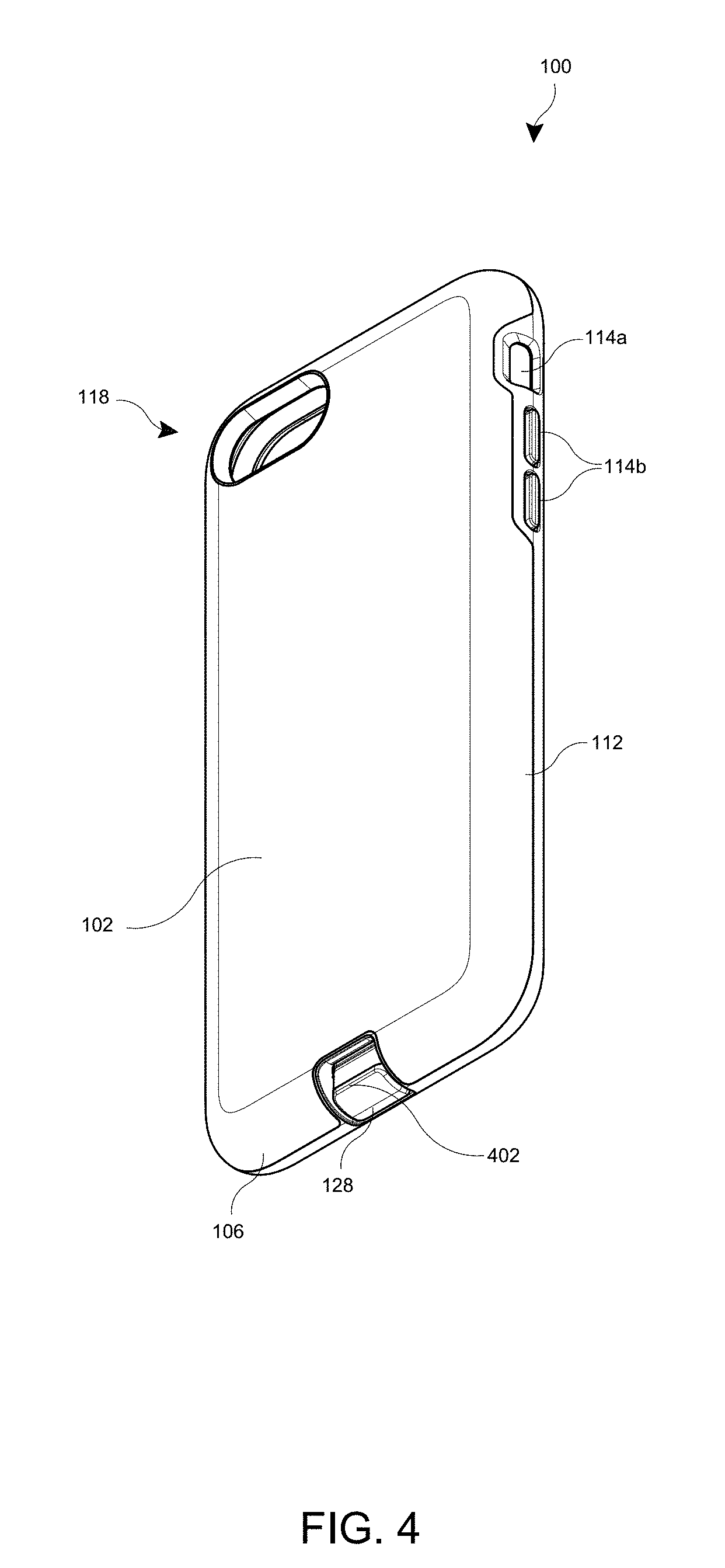
[0014] FIG. 4 is a rear perspective view of the wireless case of FIG. 3.
[0015] FIG. 5 is a front view of the wireless case of FIG. 3.
[0016] FIG. 6 is a front view of the wireless case of FIG. 3 with the wireless receiver in a disengaged position.
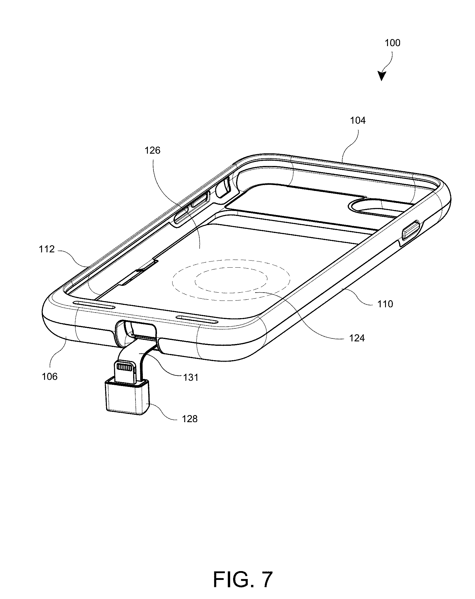
[0017] FIG. 7 is a perspective view of the wireless case of FIG. 6 with the device interface moved so as to not block an opening in a bottom wall of the wireless case.
[0018] FIG. 8 is a front partial exploded view of the case with the wireless receiver removed from the wireless case.
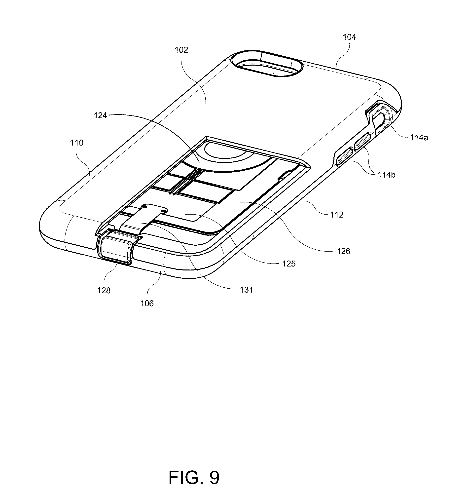
[0019] FIG. 9 is a partial cutaway view of the wireless case.
[0020] FIG. 10 is perspective view of a wireless external battery pack attached to the wireless case.
DETAILED DESCRIPTION OF CERTAIN EMBODIMENTS
[0021] FIG. 1 is a schematic view of an example embodiment of a wireless case 100 for use with a mobile electronic device 120. FIG. 2 is a schematic view of an example embodiment of a wireless case 100 and a wireless signal base 130. FIG. 3 is a front perspective view of an example embodiment of a wireless case 100 in an engaged position. FIG. 4 is a rear perspective view of the wireless case 100 of FIG. 3. FIG. 5 is a front view of the wireless case 100 of FIG. 3.
[0022] The wireless case 100 can include a back wall 102 that is configured to extend across at least a portion of a back of the mobile electronic device 120. The case 100 can include a top wall 104 configured to extend along at least a portion of a top of the mobile electronic device 120. The case 100 can include a bottom wall 106 configured to extend along at least a portion of a bottom of the mobile electronic device 120. In some embodiments, the bottom wall 106 can comprise an opening 108. The case 100 can include a right side wall 110 configured to extend along at least a portion of a right side of the mobile electronic device 120. The case 100 can include a left side wall 112 configured to extend along at least a portion of a left side of the mobile electronic device 120. The case 100 can include a front opening configured such that a display (e.g., a touchscreen configured to receive a user input such as a touch input via a finger(s) or hand(s)) of the mobile electronic device 120 is visible through the front opening when the mobile electronic device 120 is in the case 100. One or more of the back wall 102, the top wall 104, the bottom wall 106, the right side wall 110, and the left side wall 112 can be flexible such that the mobile electronic device 120 can pass through the front opening and be securely disposed within the wireless case 100. The wireless case 100 can include one or more features (e.g., openings, button covers, and/or switch covers) that are configured to provide access to one or more corresponding features (e.g., buttons, ports, and/or switches) on the mobile electronic device 120. For example, an opening (not shown) through a wall of the case 100 can be disposed to align with an input port (e.g., a headphone jack) on the mobile electronic device 120. An opening 114a through a wall of the case 100 can be disposed to align with a button or switch (e.g., a mute switch) on the mobile electronic device 120 to enable a user to operate the button or switch through the opening 114a. Button covers 114b can be disposed to align with buttons (e.g., volume buttons and/or an on/off button) on the mobile electronic device 120 to enable a user to operate the buttons via the button covers 114. In some embodiments, the case 100 can include a switch cover that is configured to interface with a switch on the mobile electronic device 120 to operate the switch. One or more openings 116 can be disposed to transfer sound from a speaker on the mobile electronic device 120 out of the case 100 and/or to transfer sound to a microphone on the mobile electronic device 120. A camera opening 118 can be positioned (e.g., through the back wall 102) to align with a camera and/or camera flash on the mobile electronic device 120 so that the camera of the mobile electronic device 120 can operate while the mobile electronic device 120 is in the case 100.
[0023] The case 100 can comprise one or more tabs 122. In some embodiments the tabs extends from the back wall 102. In some embodiments the tabs can extends from the left side and/or right sight walls 110, 112. As will be discussed in greater detail below, these tabs 122 can be configured to interact with a wireless receiver housing 126, which can enclose a wireless receiver 124, such as a coil antenna. In some figures, the wireless receiver 124 is shown by dashed lines, which can indicate the location of the internal coil antenna. The wireless receiver housing 126 can have a sandwich structure, with the wireless receiver 124 disposed between a front housing piece and a rear housing piece. The additional circuitry 125 and/or other components (e.g., wire(s) connecting the wireless receiver to the device interface 128) can also be disposed between the front and rear housing pieces. The wireless receiver housing 126 can be flexible, in some embodiments, or it can be rigid, such as to protect the wireless receiver 124 or other electrical components inside the housing 126. The back wall 102 can include a recess for receiving the wireless receiver housing 126. The recess can be larger than the wireless receiver housing 126. The recess in the back wall 102 can be configured to allow motion of the wireless receiver housing 126 in a direction away from and towards the top wall 104 and the bottom wall 106, while inhibiting motion of the wireless receiver housing 126 in a direction away from and towards the left and right side walls 110, 112. Protrusions or ridges created by the recess can serve as a guide for the wireless receiver 124. For instance, the extent to which the wireless receiver housing 126 can travel upward or downward can be dictated by the shape of the recess. In some embodiments, the range of motion of the wireless receiver housing 126 may be dictated by one or more protrusions in the back wall 102, left side wall 112, and/or right side wall 110. In some embodiments, the range of motion of the wireless receiver housing 126 is dictated by one or more of the back wall 102, the top wall 104, the left side wall 112, and right side wall 110.
[0024] The case 100 can have an external shape that generally corresponds to the external shape of the mobile electronic device 120. Accordingly, a case 100 designed for use with a smartphone can have an external shape that generally corresponds to the external shape of the smartphone. Accordingly, the case 100 with the smartphone therein can be used in the same manner as the smartphone without the case 100. For example, the case 100 with the smartphone therein can be placed in a user's pocket, can be held in a single hand with the thumb operating the touchscreen, can comfortably be held to the user's face when talking on the phone, etc. The case 100 can provide protection to the mobile electronic device 120 that is disposed therein.
[0025] As illustrated in FIG. 2, the case 100 can include a coupler 129, such as one or more magnets to facilitate alignment with a wireless charger 130 (such as a docking station, a charging pad, or a wireless external battery pack) that supports or provides wireless charging capabilities. Such alignment may facilitate proper coupling of the case 100 to the wireless charger 130 so that the wireless receiver 124 of the case 100 is properly positioned relative to the wireless transmitter 134 of the charger 130 to enable, improve, or optimize wireless charging. For example, the charger 130 may also include one or more magnets, such that when the case 100 is placed within magnetic range of the charger 130, the one or more magnets in the case 100 are pulled towards and aligned with the one or more magnets in the charger 130. Respective wireless charging input and/or output interfaces in the case 100 and the charger 130 may be positioned such that when the one or more magnets of the case 100 align with the one or more magnets of the charger 130, the wireless input/output interfaces may also be aligned or otherwise in sufficiently close proximity to enable wireless transfer of electrical power. The charger 130 may comprise a power supply 132, which can provide electrical power to the wireless transmitter 134 of the charger 130. The power supply 132 can be configured to receive electrical power from an external source (e.g., an electrical outlet). In some embodiments, the power supply 132 can be a battery, such as for a wireless external battery pack, such as described in connection with FIG. 10. The wireless charger 130 can include a wireless transmitter 134 (e.g., a wireless transmitter coil or other suitable antenna) configured to transmit wireless signals to the case 100.
[0026] The wireless charger 130 can include a coupler 136 configured to couple the case 100 with the charger 130 in a predefined position and/or orientation. In some embodiments, the coupler 136 comprises one or more magnets configured to attract with one or more magnets on the case 100. As illustrated in FIG. 2, the case 100 containing the mobile electronic device 120 can be placed adjacent to (e.g., on top of) the charger 130 in order to begin receiving wireless signals. By way of example, if a user places the case 100 onto the charger 130, but at a location where the wireless transmitter 134 and the wireless receiver 124 are positioned further apart than desired, the forces (e.g., attraction) between the magnet(s) of the case 100 and the magnet(s) of the charger 130 can cause the case 100 to move so as to bring the wireless receiver 124 closer to the wireless transmitter 134. In some embodiments, the orientation of the wireless receiver 124 relative to the wireless transmitter 134 can affect the wireless charging, and the couplers 129 and 136 can be configured to position the case 100 relative to the charger 130 such that the wireless receiver 124 is oriented relative to the wireless transmitter 134 at a charging orientation that is configured to enable, improve, or optimize wireless charging. By way of example, if a user places the case 100 onto the wireless charger 130 at an orientation that is offset rotationally by 20 degrees from the charging orientation, the forces (e.g., attraction and/or repulsion) between the magnet(s) of the case 100 and the magnet(s) of the charger 130 can rotate the case by 20 degrees to the charging orientation. In some embodiments, the system can have a single charging orientation. In some embodiments, the system can have multiple suitable charging locations (e.g., four charging locations offset from each other by 90 degrees). Many alternatives are possible. In some embodiments, the coupler 129 may be a latching or clipping mechanism configured to secure the case 100 to the charger 130 in a proper orientation. In some embodiments, the shape or design of the charger 130 and/or the case 100 may encourage a user to place the case 100 on the charger 130 in the proper orientation.
[0027] The case 100 can include a wireless receiver 124. The wireless receiver 124 can extend across at least a portion of the back wall 102 such that the wireless receiver 124 can be configured to be behind (rearward) of the back of the mobile electronic device 120. The wireless receiver 124 can be configured to receive wireless signals, such as inductive charging signals for charging the mobile electronic device 120 or data transfer (e.g., via electrical circuitry 125 inside the wireless receiver housing 126). For example, wireless charging signals can be received by the wireless receiver 124 via electromagnetic fields provided by the wireless charger 130 (e.g., through magnetic resonance, inductive power transfer, or any other kind of wireless signal transfer). In some embodiments, the wireless receiver 124 can be configured to transfer data to and/or from the mobile electronic device 120 while the mobile electronic device 120 is in the case 100. Accordingly, the mobile electronic device 120 can use the wireless receiver 124 of the case 100 to wirelessly sync with or otherwise communicate with an external computing device while in the case 100. Thus, in some embodiments, the wireless receiver 124 of the case 100 can be used for transmitting wireless signals (e.g., for data communication to an external computing device) in addition to, or instead of, receiving wireless signals. For example, the external computing device can have features similar to those discussed in connection with the wireless charger 130, wherein the wireless transmitter 134 is configured to wirelessly send and/or receive data to and/or from the wireless receiver 124 of the case 100. The external computing device can have a hardware processor and computer readable memory for sending and/or receiving data to and/or from the wireless transmitter 134 for communicating with the mobile device through the case 100. The external computing device can include the coupler 136 and/or the power supply 132, as described in connection with FIG. 2. In some embodiments, the charger 130 can connect with an external computing device. The charger 130 can then wirelessly provide the data to the wireless receiver 124. Data can be sent from the wireless receiver 124 to the device interface 128 via electrical circuitry 125 such that the data can be transferred to the mobile electronic device 120 via the device interface 128 that is coupled to the mobile device interface 121. Data from the mobile electronic device 120 can be received by the device interface 128, can be transferred to the wireless receiver 124, and can be output from the wireless receiver 124 to the base 130 and then to the external computing device. In some embodiments, the data can be wirelessly communicated directly to and/or from the external computing device, as discussed herein.
[0028] The wireless receiver 124 can receive electrical power from a power source, such as a charging pad. The wireless receiver 124 can be configured to receive a wireless charging signal. For example, the wireless receiver 124 can be enclosed inside a housing 126, which can be configured to contain a wireless charging receiver coil and other circuitry 125 (see FIG. 9). By way of example, the other circuitry 125 can include an alternating current (AC) to direct current (DC) converter, a voltage regulator, a current limiter, and/or other electrical components to facilitate charging of the mobile electronic device 120 (e.g., the battery 123 thereof) using the signals received by the wireless receiver 124. The housing can comprise one or more slots or indentations 135 that allow the one or more tabs 122 on the case 100 to pass therethrough (e.g., for insertion or removal of the wireless receiver housing 126). The wireless receiver housing 126 and the wireless receiver 124 can move within the recess formed in the back wall 102, as described above. In some embodiments, the wireless receiver housing 126 can slide in a direction away from the top wall 104 to move to a lower, or disengaged position, and can slide in a direction towards the top wall 104 to move to an upper, or engaged position. The wireless case 100 can further comprise one or more guides (e.g., tabs 122) that define a direction of motion and/or range of motion for the wireless receiver housing 126. The guides 133 of the wireless receiver housing 126 can be configured to interact with the guides (e.g., tabs 122) of the case 100 to define a range of motion for the wireless receiver housing 126. The one or more guides 133 can include thinned portion(s) of the housing that are thinner than the surrounding portions, so that the thinned portion(s) can fit under the one or more tabs 122 of the case 100. As the wireless receiver housing 126 moves within the range of motion, the thinned portion(s) of the housing can slide under the tab(s) 122. When the tab(s) 122 reach the end of the thinned portion(s) the tab(s) 122 can abut against the surrounding, thicker, portions of the housing to impede further motion of the housing 126 beyond the range of motion.
[0029] In some embodiments, the wireless receiver 124 is a wireless antenna, such as a coil antenna. As a non-limiting example, the wireless charger 130 can comprise a transmitter circuit and a transmitter coil. The transmitter circuit can send alternating current to the transmitting coil. The alternating current flowing within the transmitter coil can create a magnetic field, which extends to a receiver coil (when the case 100 is within a threshold distance from the base 130). The magnetic field generates alternating current within the receiver coil, which is converted into direct current (e.g., by an AC-DC converter in the other circuitry 125). The direct current can then be transmitted to the mobile electronic device 120 (e.g., for charging the battery 123).
[0030] The case 100 can include a device interface 128 that can be electrically coupled to the wireless receiver 124 (e.g., via electrical circuitry 125). In some embodiments, the device interface 128 can be an electrical connector that is configured to engage the mobile device interface 121 on the mobile electronic device. In some implementations, the electrical connector can extend from a movable base that is coupled to the wireless receiver housing 126. In other implementations, the electrical connector can extend upward from the bottom wall 106 of the case 100, although other locations can be used, such as extending inward from the left side wall 112 or the right side wall 110, depending on the corresponding location of the mobile device interface 121. As illustrated in FIGS. 5 and 6, the device interface 128 can move between an engaged position (see FIG. 5) and a disengaged position (see FIG. 6). The wireless receiver 124 (e.g., inside the wireless receiver housing 126) can move with the device interface 128 as the device interface 128 moves between the engaged position and the disengaged position. The device interface 128 can slide in a direction away from the top wall 104 to move to the disengaged position, and can slide in a direction towards the top wall 104 to move to the engaged position. The device interface 128 can pass through the opening in the bottom wall 106 to move from the engaged position to the disengaged position. The wireless case 100 can further comprise one or more guides that define a direction of motion and/or range of motion for the device interface 128 (e.g., the walls of the opening 108). The case 100 can define an interior area between the back wall 102, the front opening, the top wall 104, the bottom wall 106, the right side wall 110, and the left side wall 112. The device interface 128 can be positioned outside the interior area when in the disengaged position. The device interface 128 can be positioned below the lower wall 106 when in the disengaged position. In some embodiments the device interface 128 can include an actuator 402, as shown in FIG. 4, for moving the device interface 128 to and from the engaged position to the disengaged position. The actuator 402 can include a grip configured to be manipulated by a user's finger. In some embodiments, the wireless case 100 can include an opening on a back side of the case 100 that can provide access to the actuator. In some embodiments, the opening on the back side of the case 100 can be an extension of the opening in the bottom wall 106.
[0031] In the engaged position, the device interface 128 can be configured to engage a corresponding mobile device interface 121 on the mobile electronic device 120 to deliver the electrical signals from the wireless receiver 124 to the mobile electronic device 120. For example, the device interface 128 can be a Lightning.TM. connector, a Micro-USB connector, or other type of electrical connector, which can be configured to engage a corresponding Lightning.TM. port, Micro-USB port, or other electrical port on the mobile electronic device 120. In the disengaged position the device interface 128 can be configured to disengage from the corresponding mobile device interface 121 on the mobile electronic device 120. This may be done to facilitate insertion of the mobile electronic device 120 into the case 100 or removal of the mobile electronic device 120 from the case 100. In the disengaged position the wireless case 100 can permit a mobile electronic device 120 (e.g., a cell phone such as an Iphone.RTM., other smartphone, or tablet computer) to be inserted into, and/or removed from, the case 100, such as through the front opening. The device interface 128 can deliver electrical power to the mobile electronic device 120 based on the wireless charging signal.
[0032] In some embodiments, the device interface 128 and the wireless receiver 124 are electrically coupled via a flexible connector 131. It will be understood that even in the disengaged position, the device interface 128 may block the opening 108 and thereby block access to the corresponding interface of the mobile electronic device 120. Therefore, as illustrated in FIG. 7, the device interface 128 can be configured such that when the device interface 128 is in the disengaged position, it can be movable (e.g., by bending the flexible connector 131) to expose the corresponding interface 121 of the mobile electronic device 120. By moving the device interface 128 to expose the corresponding interface on the mobile electronic device 100, the case 100 can provide access for an external interface to engage the corresponding interface 121 of the mobile electronic device 120 (e.g., through the opening 108) when the device interface 128 is in the disengaged position. When coupled with an external interface, data can be transferred to and/or from the mobile electronic device 120 while the mobile electronic device 120 is in the case 100. Accordingly, the mobile electronic device 120 can sync with or otherwise communicate with an external computing device while in the case 100. For example, a cable can connect the external computing device to the corresponding interface 121 on the mobile electronic device 120 (e.g., through the opening 108, while the device interface 128 is displaced to the position shown in FIG. 7). Data can be sent from the external computing device via the cable to the corresponding interface 121 such that the data can be transferred to the mobile electronic device 120. Likewise, data can be sent from the mobile electronic device 120 to the external computing device via the cable. The mobile electronic device 120 (e.g., the battery 123 thereof) can be charged by a wired connection through a cable that extends through the opening 108, while the device interface 128 of the case 100 is in the displaced position down in FIG. 7.
[0033] As illustrated in FIG. 8, in some embodiments, the wireless receiver 124, the wireless receiver housing 126, and the device interface 128 can be entirely removed from the case 100 (e.g., in order to clean the case 100 or replace the wireless receiver 124 and/or device interface 128). In some embodiments, the wireless receiver 124 and device interface 128 can be removed from the case 100 by allowing the tabs 122 in the case 100 to pass through the slits or indentations in the wireless receiver housing 126, thereby removing the wireless receiver housing 126 from the recess, and to then cause the device interface 128 to travel toward the top wall 104 until the device interface 128 is no longer contained within the opening 108 in the bottom wall 106. The wireless receiver housing 126 and device interface 128 can be inserted by following the reverse process.
[0034] FIG. 10 is a perspective view of a wireless external battery pack 1002 attached to the wireless case 100. In some embodiments, the case 100 can be configured for use with a wireless external battery pack 1002. The wireless external battery pack 1002 may be configured to be attached to the external side of the back wall 102 of the case 100. The wireless external battery pack 1002 can be a wireless charger 130, and the features described in connection with the charger 130 can apply to the battery pack 1002. In some embodiments, the wireless external battery pack 1002 may comprise a coupling element, such as one or more magnets, which can operate as discussed herein in connection with the couplers 129 and 136 of FIG. 2. In some embodiments, the magnets are configured to operate with with corresponding magnets in the case 100 in order to facilitate proper positioning and/or alignment of the wireless transmitter 134 and the wireless receiver 124, such as to provide, improve, or optimize wireless charging capabilities. Such positioning and/or alignment may facilitate proper coupling of the wireless external battery pack 1002 and the case 100 (e.g., to enable, improve, or optimize communication between the wireless transmitter 134 and the wireless receiver 124). For example, the case 100 may also include one or more magnets, such that when the case 100 is placed within magnetic range of the wireless external battery, the one or more magnets in the case 100 are pulled towards and/or aligned with the one or more magnets in the wireless external battery pack 1002. Respective wireless charging input and/or output interfaces in the case 100 and the wireless external battery pack 1002 may be positioned such that when the one or more magnets of the case 100 align with the one or more magnets of the base 130, the wireless input/output interfaces may also be aligned and/or otherwise in sufficiently close proximity to enable, improve, or optimize wireless transfer of electrical power.
[0035] The wireless external battery pack 1002 can include a charge indicator 1004, which can be configured to indicate a charge level of the battery in the wireless external battery pack 1002. The charge indicator 1004 can include a plurality of lights, such as light emitting diodes (LEDs), and the number of lights that are illuminated can indicate the amount of charge that the battery of the wireless external battery pack 1002 has. For example, four lights can be used, and one illuminated light can correspond to about 25% charge, two illuminated lights can correspond to about 50% charge, three illuminated lights can correspond to about 75% charge, and four illuminated lights can correspond to about 100% charge. In some embodiments, the charge indicator can use different colors, the intensity of light, or a display with a text or image representation to indicate the charge level of the wireless external battery pack 1002. In some embodiments, the wireless external battery pack 1002 can include a switch or button or other user input element 1006 configured to turn the wireless external battery 1002 on and off, to initiate or terminate wireless charging, or to provide other input to the wireless external battery pack 1002. In some embodiments, the battery pack 1002 can illuminate one or more of the lights of the charge indicator 1004 in response to input received by the user input element 1006.
[0036] Unless the context clearly requires otherwise, throughout the description and the claims, the words "comprise," "comprising," "include," "including," and the like are to be construed in an inclusive sense, as opposed to an exclusive or exhaustive sense; that is to say, in the sense of "including, but not limited to." The words "coupled" or connected," as generally used herein, refer to two or more elements that can be either directly connected, or connected by way of one or more intermediate elements. Additionally, the words "herein," "above," "below," and words of similar import, when used in this application, shall refer to this application as a whole and not to any particular portions of this application. Where the context permits, words in the Detailed Description using the singular or plural number can also include the plural or singular number, respectively. The words "or" in reference to a list of two or more items, is intended to cover all of the following interpretations of the word: any of the items in the list, all of the items in the list, and any combination of the items in the list. All numerical values provided herein are intended to include similar values within a range of measurement error.
[0037] Although this disclosure contains certain embodiments and examples, it will be understood by those skilled in the art that the scope extends beyond the specifically disclosed embodiments to other alternative embodiments and/or uses and obvious modifications and equivalents thereof. In addition, while several variations of the embodiments have been shown and described in detail, other modifications will be readily apparent to those of skill in the art based upon this disclosure. It is also contemplated that various combinations or sub-combinations of the specific features and aspects of the embodiments may be made and still fall within the scope of this disclosure. It should be understood that various features and aspects of the disclosed embodiments can be combined with, or substituted for, one another in order to form varying modes of the embodiments. Any methods disclosed herein need not be performed in the order recited. Thus, it is intended that the scope should not be limited by the particular embodiments described above.
[0038] Conditional language, such as, among others, "can," "could," "might," or "may," unless specifically stated otherwise, or otherwise understood within the context as used, is generally intended to convey that certain embodiments include, while other embodiments do not include, certain features, elements and/or steps. Thus, such conditional language is not generally intended to imply that features, elements and/or steps are in any way required for one or more embodiments or that one or more embodiments necessarily include logic for deciding, with or without user input or prompting, whether these features, elements and/or steps are included or are to be performed in any particular embodiment. Any headings used herein are for the convenience of the reader only and are not meant to limit the scope.
[0039] Further, while the devices, systems, and methods described herein may be susceptible to various modifications and alternative forms, specific examples thereof have been shown in the drawings and are herein described in detail. It should be understood, however, that the disclosure is not to be limited to the particular forms or methods disclosed, but, to the contrary, this disclosure covers all modifications, equivalents, and alternatives falling within the spirit and scope of the various implementations described. Further, the disclosure herein of any particular feature, aspect, method, property, characteristic, quality, attribute, element, or the like in connection with an implementation or embodiment can be used in all other implementations or embodiments set forth herein. Any methods disclosed herein need not be performed in the order recited. The methods disclosed herein may include certain actions taken by a practitioner; however, the methods can also include any third-party instruction of those actions, either expressly or by implication.
[0040] The ranges disclosed herein also encompass any and all overlap, sub-ranges, and combinations thereof. Language such as "up to," "at least," "greater than," "less than," "between," and the like includes the number recited. Numbers preceded by a term such as "about" or "approximately" include the recited numbers and should be interpreted based on the circumstances (e.g., as accurate as reasonably possible under the circumstances, for example .+-.5%, .+-.10%, .+-.15%, etc.). For example, "about 3.5 mm" includes "3.5 mm." Phrases preceded by a term such as "substantially" include the recited phrase and should be interpreted based on the circumstances (e.g., as much as reasonably possible under the circumstances). For example, "substantially constant" includes "constant." Unless stated otherwise, all measurements are at standard conditions including ambient temperature and pressure.
* * * * *
D00000
D00001
D00002
D00003
D00004
D00005
D00006
D00007
D00008
D00009
D00010
XML
uspto.report is an independent third-party trademark research tool that is not affiliated, endorsed, or sponsored by the United States Patent and Trademark Office (USPTO) or any other governmental organization. The information provided by uspto.report is based on publicly available data at the time of writing and is intended for informational purposes only.
While we strive to provide accurate and up-to-date information, we do not guarantee the accuracy, completeness, reliability, or suitability of the information displayed on this site. The use of this site is at your own risk. Any reliance you place on such information is therefore strictly at your own risk.
All official trademark data, including owner information, should be verified by visiting the official USPTO website at www.uspto.gov. This site is not intended to replace professional legal advice and should not be used as a substitute for consulting with a legal professional who is knowledgeable about trademark law.