Method And Apparatus For A Frequency-selective Antenna
Achour; Maha
U.S. patent application number 16/195792 was filed with the patent office on 2019-05-23 for method and apparatus for a frequency-selective antenna. This patent application is currently assigned to Metawave Corporation. The applicant listed for this patent is Metawave Corporation. Invention is credited to Maha Achour.
| Application Number | 20190158130 16/195792 |
| Document ID | / |
| Family ID | 66534063 |
| Filed Date | 2019-05-23 |


| United States Patent Application | 20190158130 |
| Kind Code | A1 |
| Achour; Maha | May 23, 2019 |
METHOD AND APPARATUS FOR A FREQUENCY-SELECTIVE ANTENNA
Abstract
Examples disclosed herein relate to an antenna system. The antenna system has a transceiver unit adapted to receive a composite communication signal, wherein the composite communication signal is a mix of multiple individual communication signals transmitted at different frequencies, a radiating structure comprising multiple subarrays of radiating elements, each subarray responsive to a different frequency, and an antenna controller adapted to map each communication signal to a user equipment and adjust an electrical parameter of the radiating elements within each subarray so as to direct each individual communication signal in the composite communication signal to a corresponding user equipment.
| Inventors: | Achour; Maha; (Palo Alto, CA) | ||||||||||
| Applicant: |
|
||||||||||
|---|---|---|---|---|---|---|---|---|---|---|---|
| Assignee: | Metawave Corporation Palo Alto CA |
||||||||||
| Family ID: | 66534063 | ||||||||||
| Appl. No.: | 16/195792 | ||||||||||
| Filed: | November 19, 2018 |
Related U.S. Patent Documents
| Application Number | Filing Date | Patent Number | ||
|---|---|---|---|---|
| 62587618 | Nov 17, 2017 | |||
| Current U.S. Class: | 1/1 |
| Current CPC Class: | H04B 1/0064 20130101; H01Q 3/42 20130101; H01Q 5/30 20150115; H01Q 5/42 20150115; H01Q 1/36 20130101; H04W 72/0453 20130101; H01Q 21/0025 20130101; H01Q 21/061 20130101; H01Q 15/0086 20130101; H01Q 1/243 20130101; H04L 5/0037 20130101 |
| International Class: | H04B 1/00 20060101 H04B001/00; H01Q 5/30 20060101 H01Q005/30; H01Q 21/00 20060101 H01Q021/00; H01Q 3/42 20060101 H01Q003/42; H01Q 1/24 20060101 H01Q001/24; H04L 5/00 20060101 H04L005/00; H04W 72/04 20060101 H04W072/04; H01Q 21/06 20060101 H01Q021/06; H01Q 1/36 20060101 H01Q001/36 |
Claims
1. A frequency-selective antenna system, comprising: a transceiver unit adapted to receive a composite communication signal, wherein the composite communication signal is a mix of multiple individual communication signals transmitted at different frequencies; a radiating structure comprising multiple subarrays of radiating elements, each subarray responsive to a different frequency; and an antenna controller adapted to map each communication signal to a user equipment and adjust an electrical parameter of the radiating elements within each subarray so as to direct each individual communication signal in the composite communication signal to a corresponding user equipment.
2. The frequency-selective antenna system of claim 1, wherein the radiating structure comprises a metastructure.
3. The frequency-selective antenna system of claim 1, wherein the radiating elements comprises metamaterial cells.
4. The frequency-selective antenna system of claim 1, wherein the radiating structure radiates the multiple individual communication signals concurrently.
5. The frequency-selective antenna system of claim 1, further comprising a lookup table to store a correspondence between radiating elements and associated frequencies.
6. The frequency-selective antenna system of claim 3, wherein at least one of the metamaterial cells comprises a reactance control mechanism.
7. The frequency-selective antenna system of claim 6, wherein the reactance control mechanism is a varactor coupled between a conductive area and a conductive loop in the at least one metamaterial cell.
8. The frequency-selective antenna system of claim 6, wherein the electrical parameter comprises a reactance of the varactor changed by a reverse biased voltage.
9. A frequency-selective metastructure antenna, comprising: a first set of metastructure cells responsive to a first frequency; a second set of metastructure cells responsive to a second frequency; and a set of electrical parameter control devices, wherein each electrical parameter control device is to alter an electrical parameter of at least one metastructure cell.
10. The frequency-selective metastructure antenna of claim 9, wherein the first set and second set of metastructure cells comprise metamaterial cells.
11. The frequency-selective metastructure antenna of claim 9, wherein the first set of metamaterial cells is not responsive to the second frequency, and the second set of metamaterial cells is not responsive to the first frequency.
12. The frequency-selective metastructure antenna of claim 11, adapted to receive a composite mix of a first communication signal at a first frequency and a second communication signal at the second frequency.
13. The frequency-selective metastructure antenna of claim 8, wherein the electrical parameter comprises a reactance of the at least one metamaterial cell and the set of electrical parameter control devices comprises a varactor.
14. The frequency-selective metastructure antenna of claim 9, wherein a set of electrical parameter control devices for the first set of metastructure cells alters the reactance of the first set of metastructure cells to direct a radiation beam in a first direction.
15. The frequency-selective metastructure antenna of claim 9, wherein each metastructure cell has a corresponding electrical parameter control device and the electrical parameter of each metastructure cell is adjusted individually.
16. A method for frequency-selective transmissions from a metastructure antenna to a user, comprising: directing a transmission to a first user; assigning a first frequency to the transmission to the first user; generating the transmission at the first frequency; and controlling a frequency-selective first subarray of metastructure cells to direct the transmission to the first user.
17. The method of claim 16, further comprising controlling a frequency-selective second subarray of metastructure cells to direct another transmission to a second user.
18. The method of claim 16, further comprising storing a correspondence between metastructure cells and associated frequencies.
19. The method of claim 16, wherein the metastructure cells comprise metamaterial cells and the metastructure antenna comprises a multi-layer metastructure antenna.
20. The method of claim 20, wherein controlling a frequency-selective first subarray of metastructure cells comprises controlling a reactance of each metastructure cell.
Description
CROSS-REFERENCE TO RELATED APPLICATIONS
[0001] This application claims priority to U.S. Provisional Application No. 62/587,618, filed on Nov. 17, 2017, and incorporated herein by reference.
BACKGROUND
[0002] Current developments in the wireless communication and sensor spaces are developing more ways to target an individual user or device. In cellular communications, a system goal is to optimize efficiency and focus energy directly to a user. To achieve this level of performance, systems add additional antennas and complex circuitry that increases their cost and footprint, while incurring latency and delay in processing.
BRIEF DESCRIPTION OF THE DRAWINGS
[0003] The present application may be more fully appreciated in connection with the following detailed description taken in conjunction with the accompanying drawings, which are not drawn to scale and in which like reference characters refer to like parts throughout, and wherein:
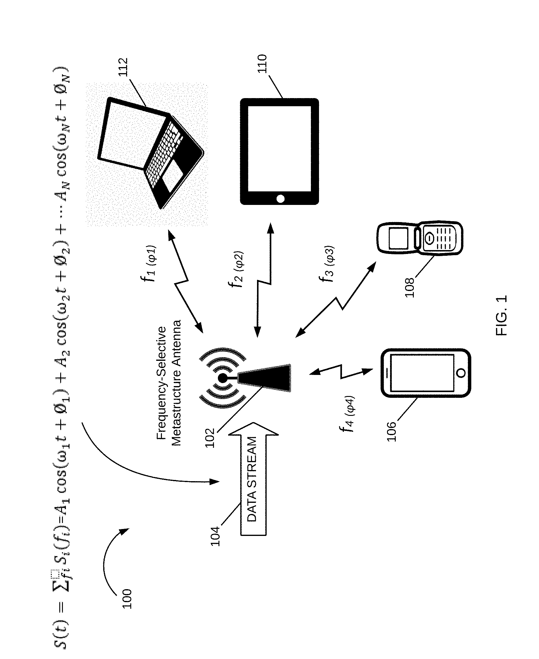
[0004] FIG. 1 is a schematic diagram of a wireless transmission system having a frequency-specific, multi-frequency antenna in accordance with various examples;
[0005] FIG. 2 illustrates a base station in accordance with various examples;
[0006] FIG. 3 is a flowchart for frequency-selective transmissions from a metastructure antenna to a user in accordance with various examples;
[0007] FIG. 4 is a schematic diagram of a frequency-selective antenna in accordance with various examples;
[0008] FIGS. 5-6 illustrate radiating element configurations in accordance with various examples;
[0009] FIG. 7 is a schematic diagram of a metastructure radiating element, a single layer metastructure array and a multi-layer metastructure array in accordance with various examples; and
[0010] FIG. 8 is a schematic diagram illustrating the operation of a wireless transmission system implemented as in FIG. 1 and in accordance with various examples.
DETAILED DESCRIPTION
[0011] Methods and apparatuses for a frequency-selective antenna are disclosed. The frequency-selective antenna incorporates metastructures that are capable of manipulating electromagnetic ("EM") waves to provide directed wireless transmission between multiple devices. In various examples, the frequency-selective antenna enables transmission of multiple signals, each having a unique frequency, wherein transmissions at a given frequency are directed to an individual user or group of users. The transmission information for the multiple signals is received as a composite information signal at the user's device, wherein the radiating elements in the metastructures are configured for specific frequencies. Each radiating element has associated electromagnetic properties, including the resonant frequency and the phase of a radiated signal, that are adjustable using a frequency-selective control applied to the radiating element. Such frequency-selective control enables transmission of a user signal from a specific radiating element at a unique frequency and phase, thereby allowing a wireless transmission system to direct specific transmissions to specific users.
[0012] It is appreciated that, in the following description, numerous specific details are set forth to provide a thorough understanding of the examples. However, it is appreciated that the examples may be practiced without limitation to these specific details. In other instances, well-known methods and structures may not be described in detail to avoid unnecessarily obscuring the description of the examples. Also, the examples may be used in combination with each other.
[0013] FIG. 1 illustrates a wireless system 100, having a transmitter 102, such as a cellular base station, Wi-Fi control point or other wireless distribution apparatus. The transmitter 102 is configured to receive a composite data stream 104 which includes information for communications with multiple mobile devices or User Equipment ("UE"), such as, for example, UE 106-112, including smart phone 106, flip phone 108, tablet 110 and laptop 112. Transmitter 102, as described in more detail below, is a frequency-selective transmitter having a metastructure antenna to provide directed wireless transmission for UE 106-112.
[0014] FIG. 2 illustrates the components of transmitter 102, implemented as transmitter 200, which includes a radiating structure 202, an antenna controller 204, a mapping storage or lookup table 206, a transceiver unit 208, memory storage 210, a power supply 212, and a communication bus 214. The transmitter 200 receives a composite data signal at transceiver unit 208 coupled to a communication bus 214 to provide received information to the radiating structure 202. The transmitter 200 also prepares messages for transmission through the radiating structure 202. In various examples, the radiating structure 202 is a metastructure configured for radiation of EM waves. A metastructure, as generally defined herein, is an engineered structure capable of controlling and manipulating EM radiation at a desired direction based on its geometry. There are a variety of structures that may be incorporated into the radiating structure 202 that enable the generation of multiple beams concurrently, as discussed herein below. The transceiver unit 208 includes the components to process radio frequency ("RF") signals, such as baseband processing capability, RF integrated circuits, analog-to-digital converters, and so forth. The modules of transmitter 200 communicate with each other directly or by way of communication bus 214.
[0015] Radiating structure 202 is configured on a substrate material, which may be part of system 100 or a separate structure. The antenna controller 204 includes a radiating element control module 216 that controls the radiating elements in radiating structure 202. In various examples and as described below with reference to FIG. 4, the radiating elements may include metamaterial ("MTM") cells with voltage controlled devices for controlling the EM parameters (e.g., phase) of each cell. The antenna controller 204 also includes a mapping module 218 to map a UE to a specific frequency.
[0016] FIG. 3 illustrates a flowchart for frequency-selective transmissions from a metastructure antenna 202 to a user in accordance with various examples. When a transmission, such as a data transmission, is directed to a first user (300), the mapping module 218 assigns a first frequency to the transmission to the first user (302). The transmissions are then generated at the first frequency (304). The frequency-selective radiating elements of the metastructure 202 that are resonant at the first frequency are then controlled by radiating element control module 216 to direct the transmission to the user (306). Directed beams are provided through voltage applied to frequency-selective radiating elements, e.g., voltage controlled MTM cells. The frequency-selective radiating elements and their associated resonant frequencies are stored in lookup table 206, and retrieved by mapping module 218.
[0017] Attention is now directed to FIG. 4, which illustrates a frequency-selective antenna 400 having an antenna feed 402 and a metastructure antenna 404. Metastructure antenna 404 has an array of radiating elements or cells 406. As illustrated, the cells 406 are uniform structures. Alternate examples may be configured to include different size and/or shape cells. In one example, each cell 406 is designed to operate in the right-handed mode positive index of refraction with phase engineering on the spatial domain to achieve the desired transmission characteristics. In another example, each cell 406 may be a MTM cell. An MTM cell is an artificially structured element used to control and manipulate physical phenomena, such as the electromagnetic properties of a signal including its amplitude, phase, and wavelength. Metamaterial cells behave as derived from inherent properties of their constituent materials, as well as from the geometrical arrangement of these materials with size and spacing that are much smaller relative to the scale of spatial variation of typical applications.
[0018] A metamaterial is a geometric design of a material, such as a conductor, wherein the shape creates a unique behavior for the device. An MTM cell may be composed of multiple microstrips, gaps, patches, vias, and so forth having a behavior that is the equivalent to a reactance element, such as a combination of series capacitors and shunt inductors. Various configurations, shapes, designs and dimensions are used to implement specific designs and meet specific constraints. In some examples, the number of dimensional degrees of freedom determines the characteristics of a cell, wherein a cell having a number of edges and discontinuities may model a specific-type of electrical circuit and behave in a given manner. In this way, an MTM cell radiates according to its configuration. Changes to the reactance parameters of the MTM cell result in changes to its radiation pattern. Where the radiation pattern is changed to achieve a phase change or phase shift, the resultant structure is a powerful antenna, as small changes to the MTM cell can result in large changes to the beamform. The array of cells 406 is configured so as to form a composite beamform. This may involve subarrays of the cells or the entire array.
[0019] The MTM cells 406 may include a variety of conductive structures and patterns, such that a received transmission signal is radiated therefrom. In some examples, each MTM cell may have unique properties. These properties may include a negative permittivity and permeability resulting in a negative refractive index; these structures are commonly referred to as left-handed materials ("LHM"). The use of LHM enables behavior not achieved in classical structures and materials, including interesting effects that may be observed in the propagation of electromagnetic waves, or transmission signals. Metamaterials can be used for several interesting devices in microwave and terahertz engineering such as antennas, sensors, matching networks, and reflectors, such as in telecommunications, automotive and vehicular, robotic, biomedical, satellite and other applications. For antennas, metamaterials may be built at scales much smaller than the wavelengths of transmission signals radiated by the metamaterial. Metamaterial properties come from the engineered and designed structures rather than from the base material forming the structures. Precise shape, dimensions, geometry, size, orientation, arrangement and so forth result in the smart properties capable of manipulating electromagnetic waves by blocking, absorbing, enhancing, or bending waves.
[0020] In some examples, at least one of the MTM cells is coupled to a reactance control mechanism, such as a varactor to change the capacitance and/or other parameters of the MTM cell. By changing a parameter of the MTM cell, the resonant frequency is changed, and therefore, the array 406 may be configured and controlled to respond to multiple frequency bands. An example of such a cell is illustrated as MTM cell 408. MTM cell 408 has a conductive outer portion or loop 410 surrounding a conductive area 412 with a space in between. Each MTM cell 406 may be configured on a dielectric layer, with the conductive areas and loops provided around and between different MTM cells. A voltage controlled variable reactance device 414, e.g., a varactor, provides a controlled reactance between the conductive area 412 and the conductive loop 410. Varactor 414 is controlled by MTM cell control 418. The controlled reactance is controlled by an applied voltage, such as an applied reverse bias voltage in the case of a varactor. The change in reactance changes the behavior of the MTM cell 408. The voltage control is performed by MTM cell control 418 in response to identification of a position of the UE with respect to the system 100. The transceiver unit 208 provides this direction information and acts to instruct the MTM cell control 418 as to where to direct the beam.
[0021] A transmission signal 416 is provided to the antenna feed 402, wherein the transmission signal includes communication information for multiple UEs. Antenna feed 402 has a plurality of transmission lines for distributing the signal 416 to the metastructure antenna 404. The transmission signal for each UE has a corresponding frequency at which certain MTM cells 406 resonate. For example, the top row of MTM cells 406 are at a first frequency f.sub.1, and they resonate or radiate at frequency f.sub.1, but do not radiate EM signals at other frequencies. Similarly, the other rows of MTM cells 406 are each resonant at specific frequencies, and not respond to other frequencies. In this way, the MTM cells 406 act as specific band-pass filters.
[0022] FIGS. 5-6 illustrate example configurations for radiating elements that may be used in the metastructure antenna 404. The structure of the radiating elements and the configurations illustrated are designed to accommodate the desired frequency bands. In FIG. 4, the radiating elements are organized into rows, wherein each row includes cells that resonate at a given frequency or range of frequencies. In the illustrated examples of FIGS. 5-6, the shape, size, and position of the cells are designed to respond to multiple frequency bands. The specific configuration may be designed to achieve application considerations. Cell 502 in FIG. 5 may be an MTM cell, a patch cell with a surrounding loop, or another such structure that when in an array of cells constitutes a metastructure array as in metastructure array 506. The array of cells 502 may be an array having rows of cells of different sizes, as in arrays 504-506.
[0023] In another example, each cell may have an hexagonal shape as in cell 508 to provide design flexibility for a densely packed array. Each cell 508 has an outer geometric shape, referred to herein as a hexagonal conductive loop, e.g., loop 510, and an inner geometric shape that is referred to as a hexagonal conductive patch, e.g., patch 512. The hexagonal shape provides the flexibility of design for a densely packed array, e.g., arrays 514-516, and the parametric shape enables computational design that can be easily scaled and modified while maintaining the basic shape of the hexagon. In this example, the dimensions of the shapes are geometrically similar and their relationship is proportionally maintained.
[0024] As illustrated, the sides of the hexagonal loop 510 are designated by reference letter "a" and the sides of the hexagonal patch 512 are designated by reference letter "b". The hexagonal patch 512 is centered within the hexagonal loop 510. Corresponding points on the perimeters of the loop and patch are equidistant from each other, specifically in this example, at a distance designated by "d". This configuration is repeated to form a densely packed lattice. FIG. 6 illustrates examples of scaling of various hexagonal radiating elements, and their positioning within lattices 600-608. There is a large variety of hexagonal shapes and configurations that may be implemented, both symmetric and asymmetric. Note also that although illustrated as having a hexagonal shape, a radiating element may be of another shape, e.g., circular, rectangular, etc., depending on the application. A variety of sizes, configurations and designs may be implemented.
[0025] In FIG. 7, a metastructure radiating element 700 is shown to have a rectangular shape. The metastructure radiating element 700 can be arranged in a metastructure array structure 702 as in the metastructure array of cells 406 in FIG. 4. Note that in structure 702, the radiating elements are spaced apart by a distance that is determined based on the desired radiation pattern and beam characteristics. Note also that a radiating array structure may be implemented as a layer in a multi-layer radiating array, such as metastructure radiating layers 704 having 4 layers of 8.times.8 radiating arrays. The number of elements in an array, the shape of the elements, the spacing between the elements, and the number of layers can all be designed to achieve a desired performance and desired multi-frequency response, with subarrays responding to different frequencies.
[0026] In some examples, each portion of the cells, or subarray of cells, is responsive to a first frequency. The subarray of cells are configured to operate together and thus to direct communications to a given user or in a specific direction. This may be used in a cellular communication system to direct a communication stream to a given user and maximize available transmission energy to that user, and thus increase the throughput to that user. This is a consideration in many applications, such as in video streaming to a mobile device. In a congested environment, it helps the transmission to each user, and allows the system to adjust the energy used for each transmission. For example, the system 100 of FIG. 1 may detect that a user that is in a video chat, a second user on an audio call, and a third user that is streaming a sports game. The system 100 is able to determine the bandwidth and throughput requirements of each of the users. This information is then used to adjust the transmission directly to each user and balance the available transmission energy accordingly. In some examples, the cells in an antenna lattice include varactors, or electrical parameter controllers, that enable the system to change the resonant frequency of a given cell or subarray of cells. In this way, the system is able to configure the cells into a variety of subarrays.
[0027] The examples of FIGS. 5-7 provide methods and apparatuses for providing multiple frequency signals from a single metastructure antenna having cells of different resonant frequencies in a wireless transmission system. The frequencies supported determine the shape and configuration of the cells, which may be positioned in an array or lattice configuration. In some examples, an antenna controller, e.g., controller 204 of FIG. 2, adjusts the EM characteristics of one or more cells to direct a transmission beam to a UE. The antenna system receives the composite signal of information for multiple users and assigns a frequency to each user. The metastructure antenna has subarrays of cells that respond to each of the frequencies. FIG. 8 illustrates operation of system 100 of FIG. 1, wherein transmission to each UE 802-808 from metastructure antenna 800 is at the corresponding frequency assigned to that user.
[0028] In the illustrated example, a first user receives signals at frequency f.sub.1, and the antenna controller adjusts the EM parameters of the subarray of cells that respond to the frequency f.sub.1. The adjustment changes the phase of individual cells such that their combined radiation forms a beam directed at the user. The beam direction concentrates energy to that user. In some situations, the beam is a pencil beam, or very thin beam, and in other situations, such as a multi-cast to multiple users, the beam may be sized to reach multiple users with a same transmission. As the subarrays responsive to frequency f.sub.1 are not responsive to the other frequencies, they do not radiate these frequencies of the composite signal, which includes all the frequencies. Each subarray responds to its frequency, while the other frequencies have little to no effect on that subarray. This concurrent transmission to multiple users with a frequency-selective directed antenna enables increases in throughput of a wireless system.
[0029] In some systems, the subarrays may be used for different functions, such as one subarray for cellular communications and another for functions using the Industrial, Scientific, Medical ("ISM") band. The ability for a single metastructure antenna array to provide multiple frequency transmissions is a great improvement over other wireless systems. The metastructure antenna described above is particularly applicable for directed beam generation in a wireless transmission device. This directivity may be used to improve the capabilities of a communication system, such as to enable 5th Generation ("5G") communications.
[0030] It is appreciated that the previous description of the disclosed examples is provided to enable any person skilled in the art to make or use the present disclosure. Various modifications to these examples will be readily apparent to those skilled in the art, and the generic principles defined herein may be applied to other examples without departing from the spirit or scope of the disclosure. Thus, the present disclosure is not intended to be limited to the examples shown herein but is to be accorded the widest scope consistent with the principles and novel features disclosed herein.
* * * * *
D00000
D00001
D00002
D00003
D00004
D00005
D00006
D00007
D00008
XML
uspto.report is an independent third-party trademark research tool that is not affiliated, endorsed, or sponsored by the United States Patent and Trademark Office (USPTO) or any other governmental organization. The information provided by uspto.report is based on publicly available data at the time of writing and is intended for informational purposes only.
While we strive to provide accurate and up-to-date information, we do not guarantee the accuracy, completeness, reliability, or suitability of the information displayed on this site. The use of this site is at your own risk. Any reliance you place on such information is therefore strictly at your own risk.
All official trademark data, including owner information, should be verified by visiting the official USPTO website at www.uspto.gov. This site is not intended to replace professional legal advice and should not be used as a substitute for consulting with a legal professional who is knowledgeable about trademark law.