Dual-sided Receptacle Connector
LITTLE; TERRANCE F.
U.S. patent application number 16/186487 was filed with the patent office on 2019-05-23 for dual-sided receptacle connector. The applicant listed for this patent is FOXCONN INTERCONNECT TECHNOLOGY LIMITED, FOXCONN (KUNSHAN) COMPUTER CONNECTOR CO., LTD.. Invention is credited to TERRANCE F. LITTLE.
| Application Number | 20190157810 16/186487 |
| Document ID | / |
| Family ID | 66496373 |
| Filed Date | 2019-05-23 |


View All Diagrams
| United States Patent Application | 20190157810 |
| Kind Code | A1 |
| LITTLE; TERRANCE F. | May 23, 2019 |
DUAL-SIDED RECEPTACLE CONNECTOR
Abstract
The first type adaptor cable assembly has an inner connector equipped with a plug board derived from the FP5 for mating with the FP5 vertical receptacle connector, and an outer connector configured to be in compliance with the FP5 or QSFP-DD receptacle connector and disposed at a rear end of the cage for mating with the FP5 or QSFP-DD inserted into the cage. Notably, the connection between the inserted FP5 and QSFP-DD and the corresponding FP5 or QSFP-DD receptacle connector directly attached/linked to the adaptor cable, is same with the traditional connection between the inserted FP5 or QSFP-DD and the corresponding receptacle connector which is only mounted to the main/external printed circuit board without directly attachment to the cable.
| Inventors: | LITTLE; TERRANCE F.; (Fullerton, CA) | ||||||||||
| Applicant: |
|
||||||||||
|---|---|---|---|---|---|---|---|---|---|---|---|
| Family ID: | 66496373 | ||||||||||
| Appl. No.: | 16/186487 | ||||||||||
| Filed: | November 10, 2018 |
Related U.S. Patent Documents
| Application Number | Filing Date | Patent Number | ||
|---|---|---|---|---|
| 62584751 | Nov 11, 2017 | |||
| Current U.S. Class: | 1/1 |
| Current CPC Class: | H01R 9/0515 20130101; H01R 12/724 20130101; G02B 6/4249 20130101; H01R 13/659 20130101; H01R 9/0512 20130101; G02B 6/4277 20130101; G02B 6/3897 20130101; H01R 12/75 20130101; H01R 24/60 20130101; H01R 13/6583 20130101; G02B 6/43 20130101; H01R 13/6587 20130101; H01R 13/6592 20130101; H01R 12/72 20130101; H01R 13/514 20130101; H05K 5/00 20130101; G02B 6/4292 20130101 |
| International Class: | H01R 13/6583 20060101 H01R013/6583; H01R 13/659 20060101 H01R013/659; H01R 13/6592 20060101 H01R013/6592; H01R 13/6587 20060101 H01R013/6587; H01R 13/514 20060101 H01R013/514; H01R 12/75 20060101 H01R012/75; H01R 12/72 20060101 H01R012/72; H01R 24/60 20060101 H01R024/60; H01R 9/05 20060101 H01R009/05 |
Claims
1. A dual-sided receptacle connector adapted for being mounted on a printed circuit board, comprising: an insulative housing defining an inner port and an outer port opposite to each other along a front-to-back direction; and a contact module received in the insulative housing; wherein the contact module comprises a plurality of outer mating portions received in the outer port, a plurality of inner mating portions received in the inner port, and at least one tail for being mounted to the printed circuit board, all of the inner mating portions and the at least one tail electrically connected with the outer mating portions, respectively.
2. The dual-sided receptacle connector as claimed in claim 1, wherein each of the inner mating portions is unified together as one piece with corresponding one of the outer mating portions.
3. The dual-sided receptacle connector as claimed in claim 1, wherein the inner mating portions and the outer mating portions are extend along a first direction, and the at least one of the tail extends along a second direction perpendicular to the first direction.
4. The dual-sided receptacle connector as claimed in claim 1, wherein the outer mating portions are arranged in an outer upper row and an outer lower row faced with the outer upper row, and the inner mating portions are arranged in an inner upper row and an inner low row faced with the inner upper row each other.
5. The dual-sided receptacle connector as claimed in claim 4, wherein there are a plurality of tails arranged in two rows, one row of the tails connected with the corresponding mating portions arranged in the outer upper row respectively, the other row of the tails connected with the corresponding mating portions arranged in the outer lower row respectively.
6. The dual-sided receptacle connector as claimed in claim 4, wherein the outer upper row of the outer mating portions are fixed in an outer upper insulator, the outer lower row of the outer mating portions fixed in an outer lower insulator, the inner upper row of the inner mating portions fixed in an inner upper insulator, the inner lower row of the inner mating portions fixed in an inner lower insulator.
7. The dual-sided receptacle connector as claimed in claim 1, wherein the outer mating portions are formed as an outer large upper part associated with an outer small upper part, and outer large lower part associated with an outer small lower part.
8. The dual-sided receptacle connector as claimed in claim 7, further comprising an outer upper grounding sheet disposed between the outer large upper part and the outer small upper part, and an outer lower grounding disposed between the outer large lower part and the outer small lower part.
9. The dual-sided receptacle connector as claimed in claim 7, wherein the inner mating portions are formed as an inner large upper part associated with an inner small upper part, and inner large lower part associated with an inner small lower part.
10. The dual-sided receptacle connector as claimed in claim 9, further comprising an inner upper grounding sheet disposed between the inner large upper part and the inner small upper part, and an inner lower grounding sheet disposed between the inner large lower part and the inner small lower part.
11. The dual-sided receptacle connector as claimed in claim 9, further comprising a top metallic top cover attached on an upper face of the outer large upper part and the inner large upper part.
12. The dual-sided receptacle connector as claimed in claim 9, further comprising a top metallic bottom cover attached on a bottom face of the outer large lower part and the inner large lower part.
13. The dual-sided receptacle connector as claimed in claim 1, wherein the dual-sided receptacle connector has a stacked structure comprising a pair of inner ports spaced apart from each along a vertical direction, and a pair of outer ports spaced apart from each along the vertical direction.
14. The dual-sided receptacle connector as claimed in claim 1, wherein some of said outer mating portions are mechanically and electrically connected to a plurality of tails which are mounted upon the printed circuit board while none of said inner mating portions are electrically and mechanically connected to any tails which are mounted upon the printed circuit board.
15. The dual-sided receptacle connector as claimed in claim 1 wherein said including: an inner large upper parts associated with an inner small upper parts with an inner upper grounding sheet therebetween and commonly exposed at an upper level of the inner port; an outer large upper part associated with an outer small upper part with an outer upper grounding sheet therebetween and commonly exposed at the upper level of the outer port; an inner large lower part associated with an inner small lower part with an inner lower grounding sheet therebetween and commonly exposed at a lower level of the inner port; an outer large lower part associated with an outer small lower part with an outer lower grounding sheet therebetween and commonly exposed at the lower level of the outer port; wherein each of said inner large upper part, said inner small upper part, said outer large upper part, said outer small upper part, said inner large lower part, said inner small lower part, said outer large lower part and said outer small lower part has the corresponding contacts, and the contacts of the inner large upper part and those of the outer large upper part are connected with each other, respectively, the contacts of the inner small upper part and those of the outer small upper part are connected with each other, respectively, the contacts of the inner large lower part and those of the outer large lower part are connected with each other, respectively, and the contacts of the inner small lower part and those of the outer small lower part are connected with each other, respectively.
16. An electrical system comprising: a main printed circuit board; a receptacle connector mounted on the main printed circuit board comprising an outer port for being mated with an outer mating plug; a IC mounted on the main printed circuit board and spaced apart a distance from the receptacle connector; and a cable assembly electrically connected between the receptacle connector and the IC; wherein the receptacle connector comprises at least one of high speed contact electrical connected with the cable, and at least one low speed contact directly connected with the printed circuit board.
17. The electrical system as claimed in claim 16, wherein the receptacle connector comprises an inner port, the cable assembly inserted into the inner port to mate with the receptacle connector.
18. An electrical connector assembly comprising: a main printed circuit board; a metallic cage mounted upon an outer side of the main printed circuit board; a vertical receptacle connector mounted upon an inner side of the main printed circuit board and defining an inner receiving slot; a horizontal receptacle connector mounted upon the outer side of the main printed circuit board and located in a rear end of the cage and defining an outer receiving slot; wherein the horizontal receptacle connector includes a plurality of high speed contacts connected to a cable which is integrally formed with the horizontal receptacle connector, and a plurality of non-high speed contacts directly electrically and mechanically connected to the main printed circuit board; wherein said cable includes a mating board at a free end to be received within the inner receiving slot of the vertical receptacle connector.
19. The electrical connector assembly as claimed in claim 18, wherein the inner receiving and the outer receiving slot have a same configuration.
20. The electrical connector assembly as claimed in claim 19, wherein the high speed contacts are connected to the cable via a paddle card.
Description
BACKGROUND OF THE INVENTION
1. Field of the Invention
[0001] The present invention relates to an electrical connector assembly, especially to the electrical connection with the external pluggable module via a dual-sided receptacle connector or a directly attached receptacle connector linked to an adaptor cable assembly by following the spirit of the previous designs of which the provisional applications have a Ser. No. 62/367,098 filed on Jul. 26, 2016, 62/399,272 filed on Sep. 23, 2016, 62/412,841 filed on Oct. 26, 2016, 62/425,627 filed on Nov. 23, 2016, 62/449,133 filed on Jan. 23, 2017, 62/509,141 filed on May 21, 2017, 62/522,113 filed on Jun. 20, 2017, and 62/533,131 filed on Jul. 17, 2017.
2. Description of Related Art
[0002] The traditional design used for connecting two sub-systems respectively on two printed circuit boards, discloses a linking cable with at one end a LEC plug connector mated to a receptacle connector embedded in the ASIC, and at the other end two port IFP plug connectors mated to on one side the so-called Interposer with IFT receptacle connector, and the other side thereof further configured with two ports of QSFP-28.
[0003] A standardized mechanisms are expected to be used to place the above-mentioned structures.
SUMMARY OF THE INVENTION
[0004] Two approaches are arranged for achieving the above-mentioned connection in the invention.
[0005] To achieve the above-mentioned object, an adaptor cable is used to connect between, on one end, the FP5 vertical receptacle connector which is on an inner side of the printed circuit board and closer to the ASIC, and, on the other end, an FP5 or a QSFP-DD which is inserted into the corresponding cage on an outer side of the printed circuit board. The first type adaptor cable assembly has an inner connector equipped with a plug board derived from the FP5 for mating with the FP5 vertical receptacle connector, and an outer connector configured to be in compliance with the FP5 or QSFP-DD receptacle connector and disposed at a rear end of the cage for mating with the FP5 or QSFP-DD inserted into the cage. Notably, the connection between the inserted FP5 and QSFP-DD and the corresponding FP5 or QSFP-DD receptacle connector directly attached/linked to the adaptor cable, is same with the traditional connection between the inserted FP5 or QSFP-DD and the corresponding receptacle connector which is only mounted to the main/external printed circuit board without directly attachment to the cable.
[0006] The second type adaptor cable assembly has the inner connector same with that of the first type adaptor cable assembly, and the outer connector equipped with a plug board derived from the QSFP-DD for mating within an inner side port of a dual-sided QSFP-DD receptacle connector or a so-called extender or adaptor which is placed at the rear end of the cage to replace the traditional one sided receptacle connector.
[0007] Notably, the contacts of either the directly attached receptacle connector in the first type adaptor cable or the dual-sided receptacle connector with direct attachment to the adaptor cable, essentially are essentially not directly mounted upon the printed circuit board but either directly or indirectly connected to the adaptor cable optionally except the so-called side-band signal contacts located at the center region thereof. Understandably, in the invention the adaptor or fly-over cable are used to replace the connection via the circuit traces on the printed circuit board for better electrical characteristics during high speed transmission.
[0008] Other objects, advantages and novel features of the invention will become more apparent from the following detailed description when taken in conjunction with the accompanying drawings.
BRIEF DESCRIPTION OF THE DRAWINGS
[0009] FIG. 1(A) is a perspective view of an electrical system according to a first embodiment of the invention;
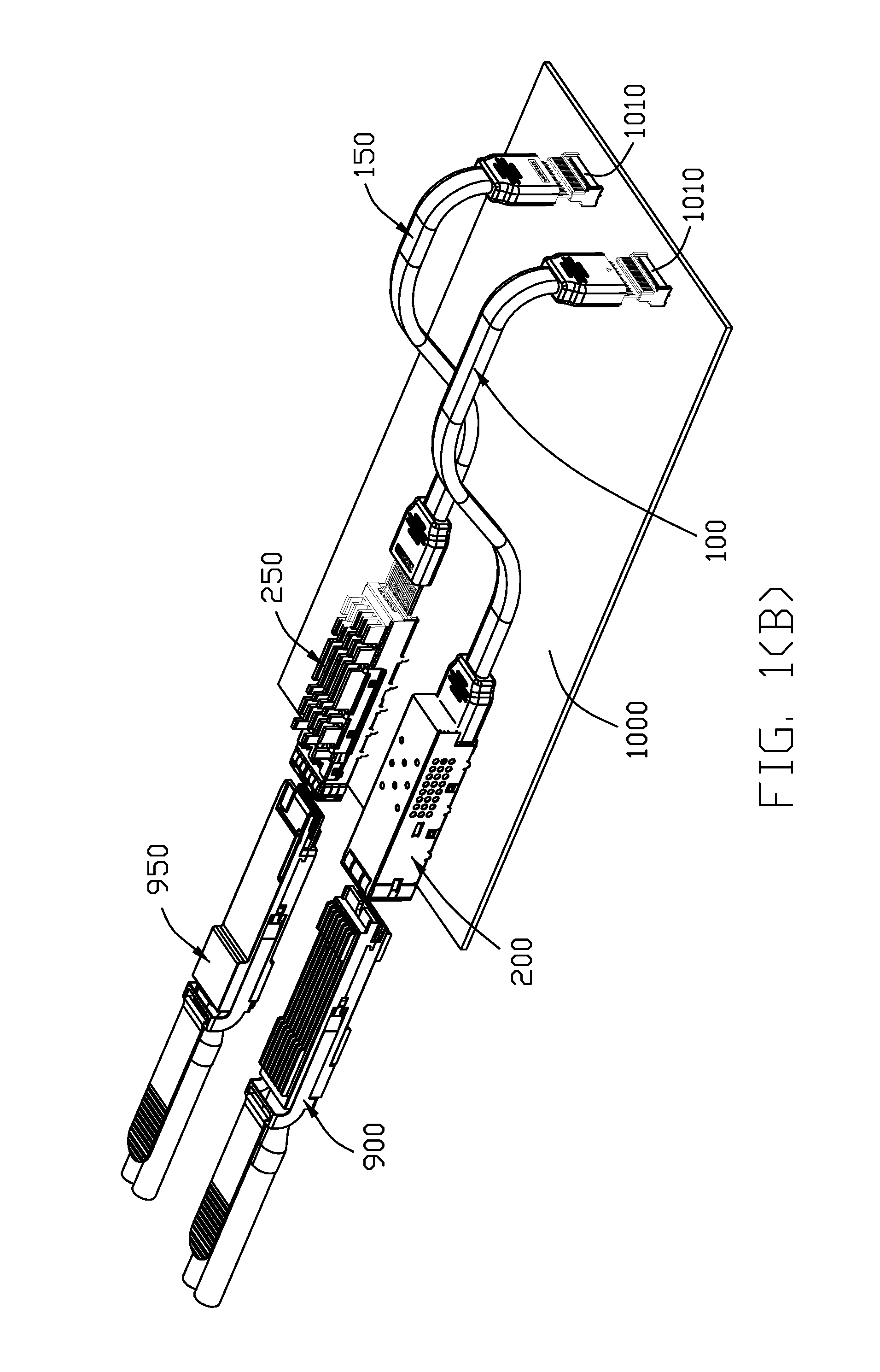
[0010] FIG. 1(B) is another perspective view of an electrical system of FIG. 1(A);
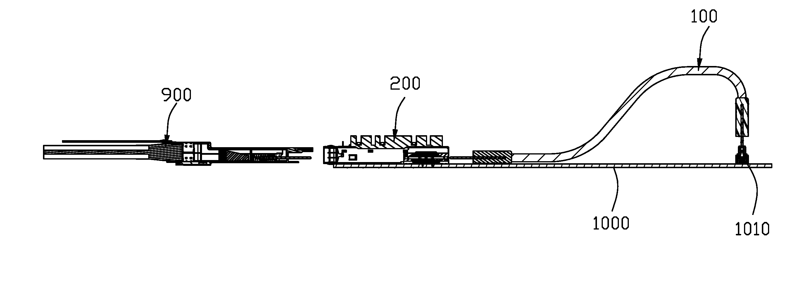
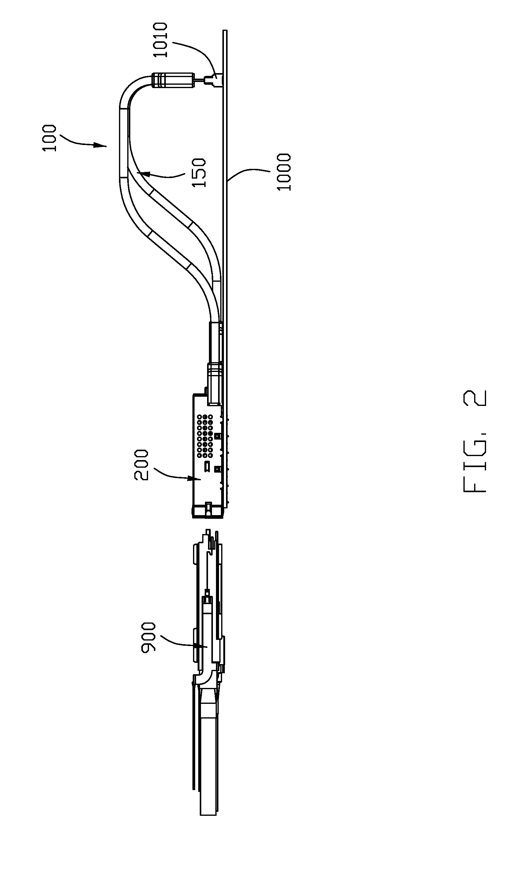
[0011] FIG. 2 is a side view of the electrical system of FIG. 1(A);
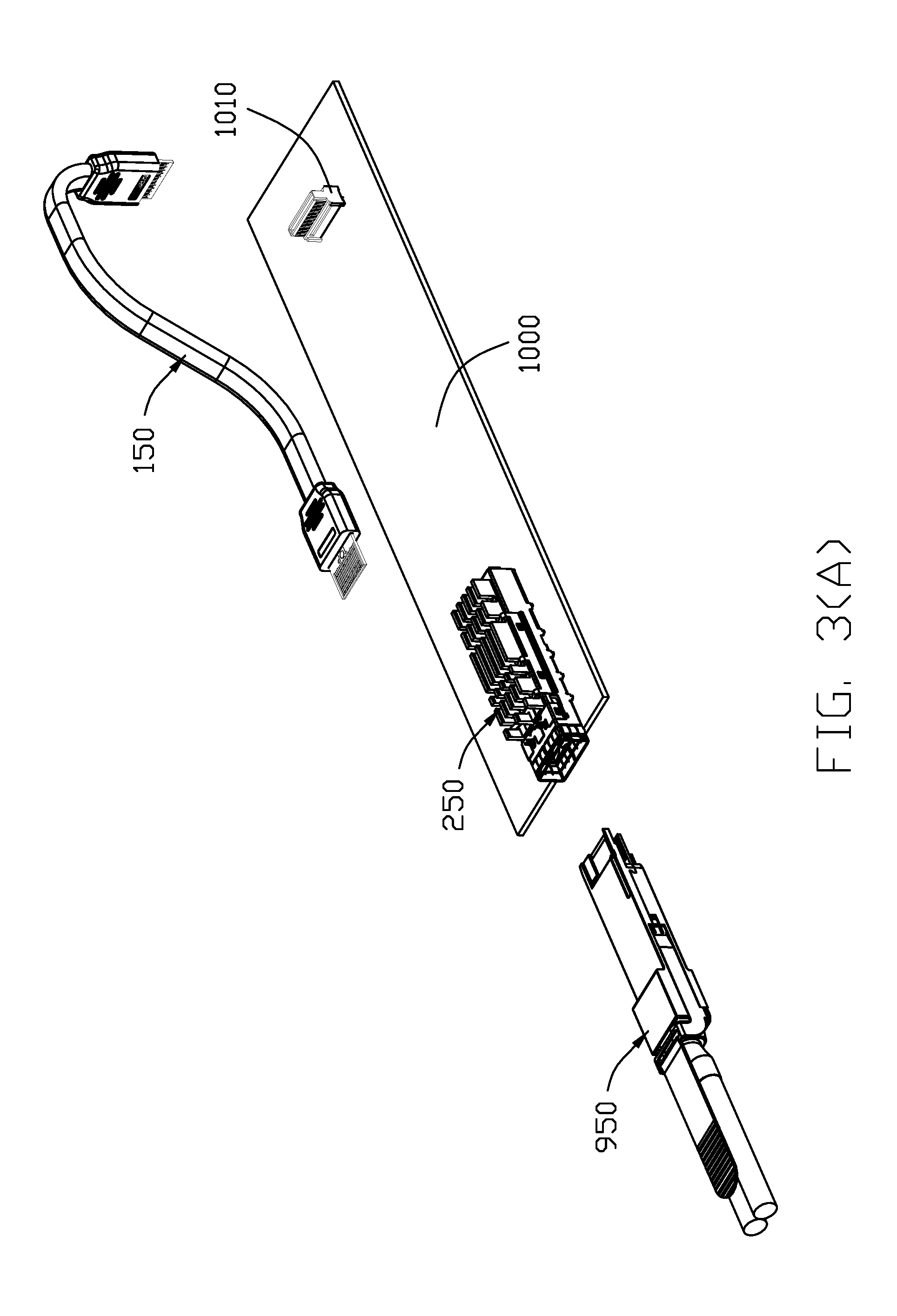
[0012] FIG. 3(A) is an exploded perspective view of a first half of the electrical system of FIG. 1(A);
[0013] FIG. 3(B) is another exploded perspective view of the first half of the electrical system of FIG. 3(A);
[0014] FIG. 4(A) is an exploded perspective view of a second half of the electrical assembly of FIG. 1(A);
[0015] FIG. 4(B) is another exploded perspective view of the second half of the electrical system of FIG. 4(A);
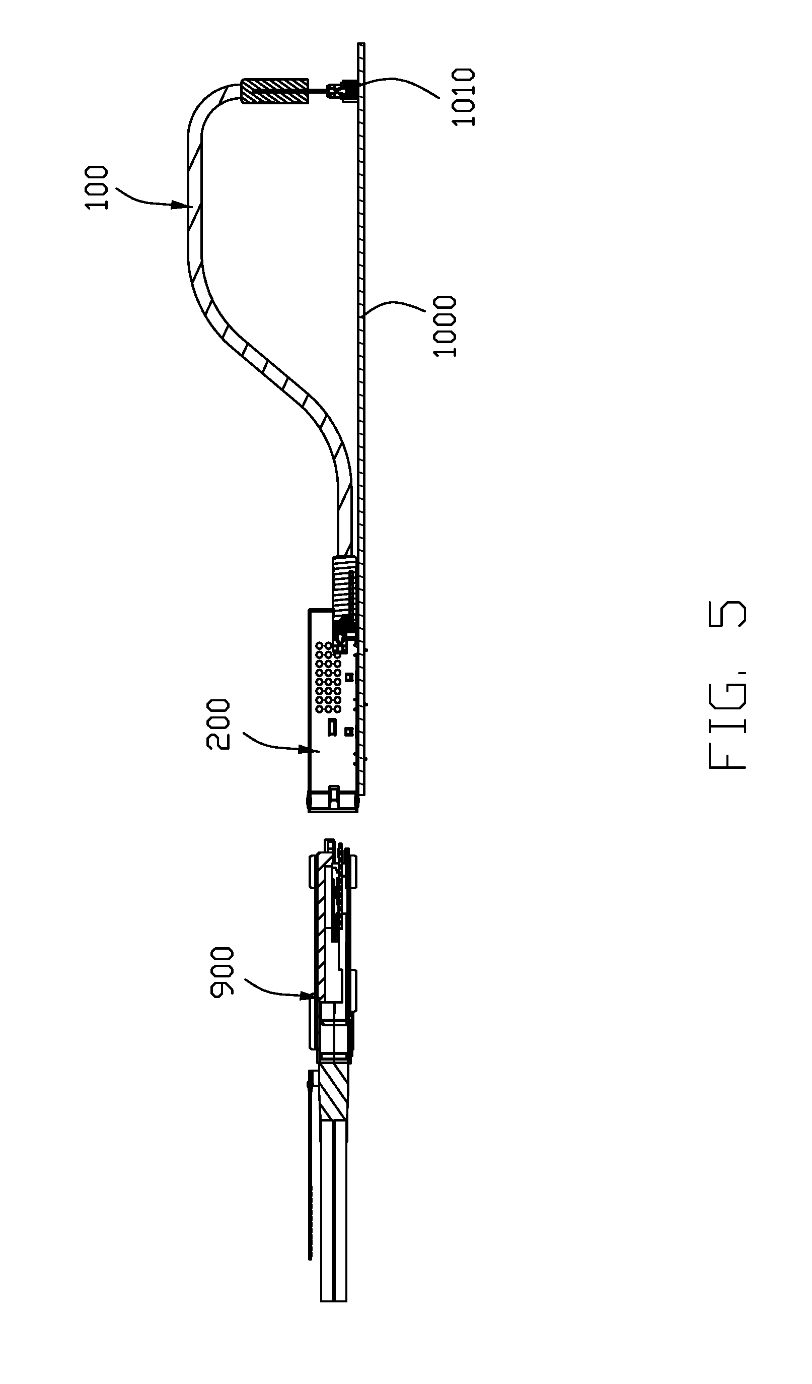
[0016] FIG. 5 is a side view of the second half of the electrical system of FIG. 4(A);
[0017] FIG. 6 is a side view of the first half of the electrical system of FIG. 3(A) wherein the reference numerals are mistyped with those of the second half;
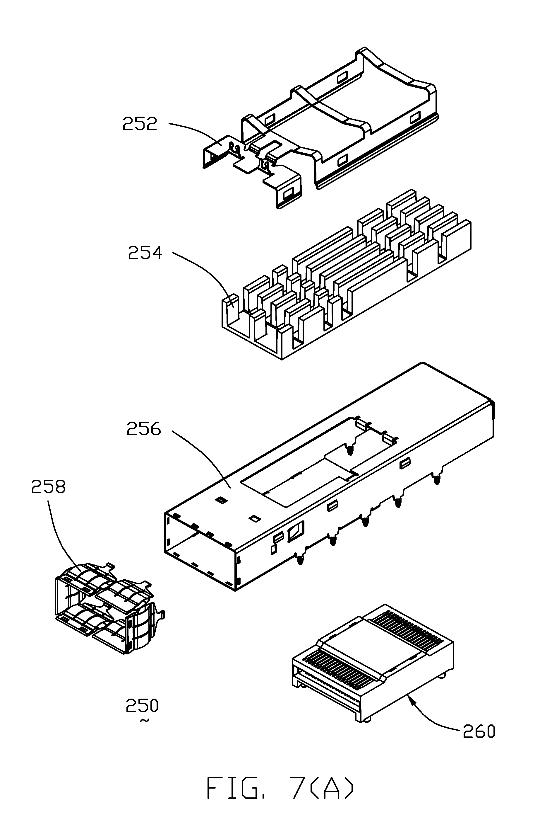
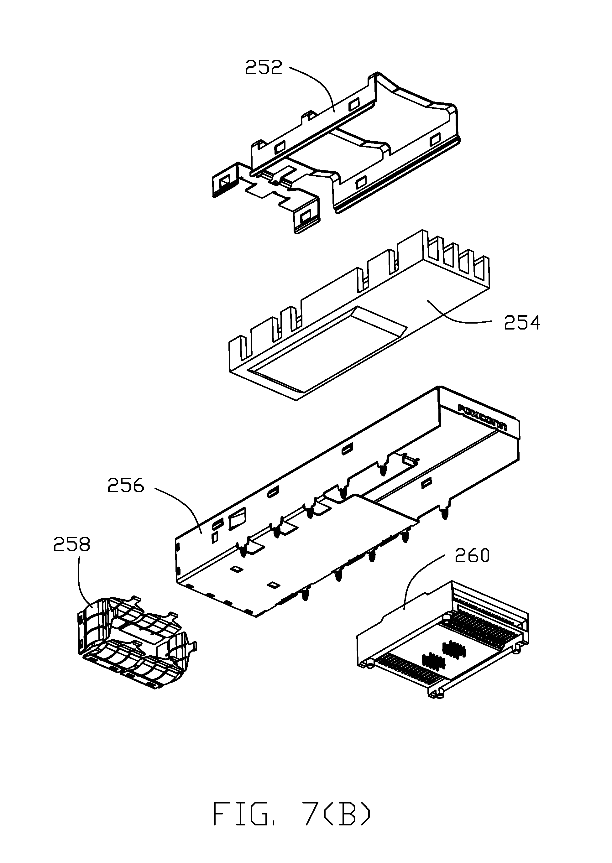
[0018] FIG. 7(A) is an exploded perspective view of the module insertion port assembly of the first half of the electrical system of FIG. 3(A);
[0019] FIG. 7(B) is another exploded perspective view of the module insertion port assembly of the first half of the electrical system of FIG. 7(A);
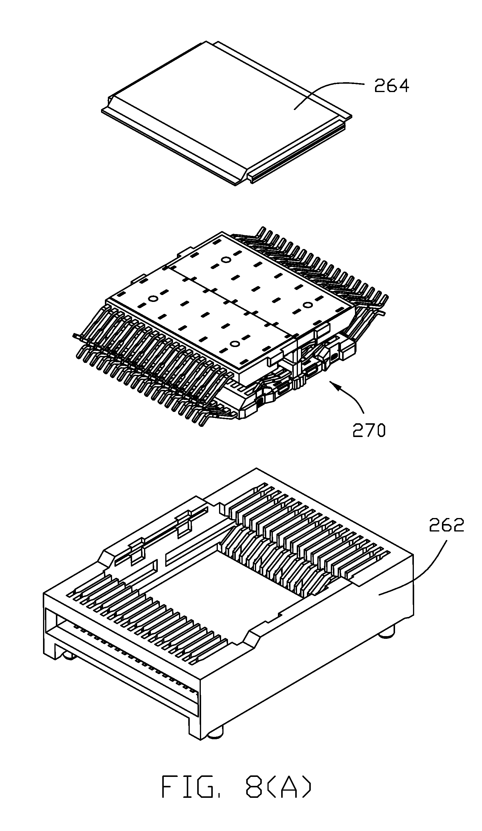
[0020] FIG. 8(A) is an exploded perspective view of the dual-sided receptacle connector of the module insertion port assembly of the first half of the electrical system of FIG. 7(A);
[0021] FIG. 8(B) is another exploded perspective view of the dual-sided receptacle connector of the module insertion port assembly of the first half of the electrical system of FIG. 8(A);
[0022] FIG. 9 is an FP5 vertical receptacle connector of the first half of the electrical system of FIG. 3(A);
[0023] FIG. 10 is a further exploded perspective view of the FP5 vertical receptacle connector of the first half of the electrical system of FIG. 9;
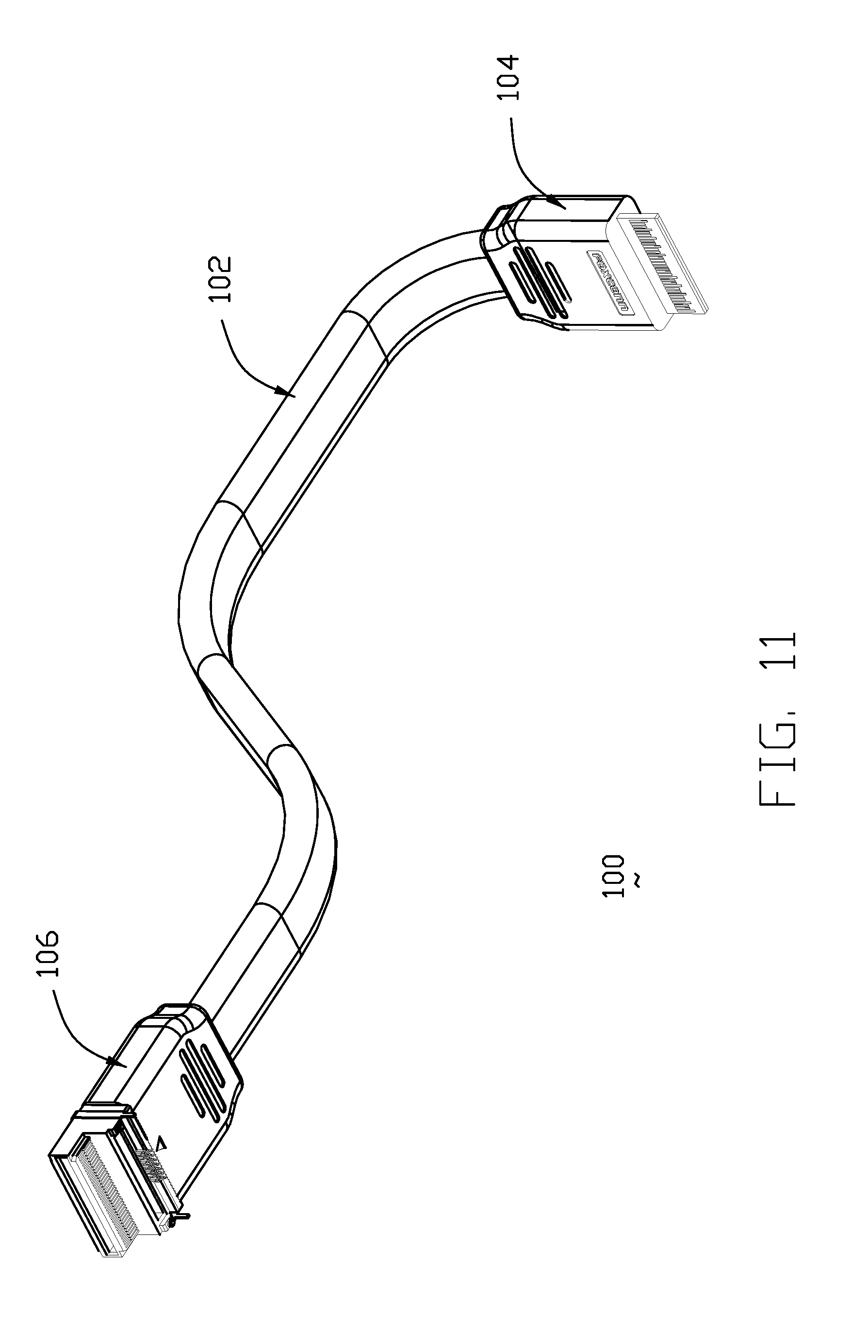
[0024] FIG. 11 is a perspective view of the adaptor cable of the second half of the electrical system of FIG. 4(A);
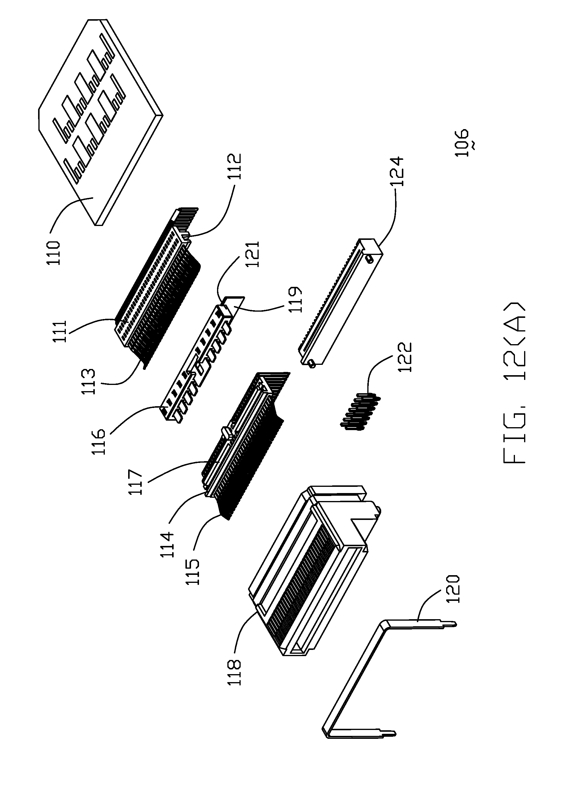
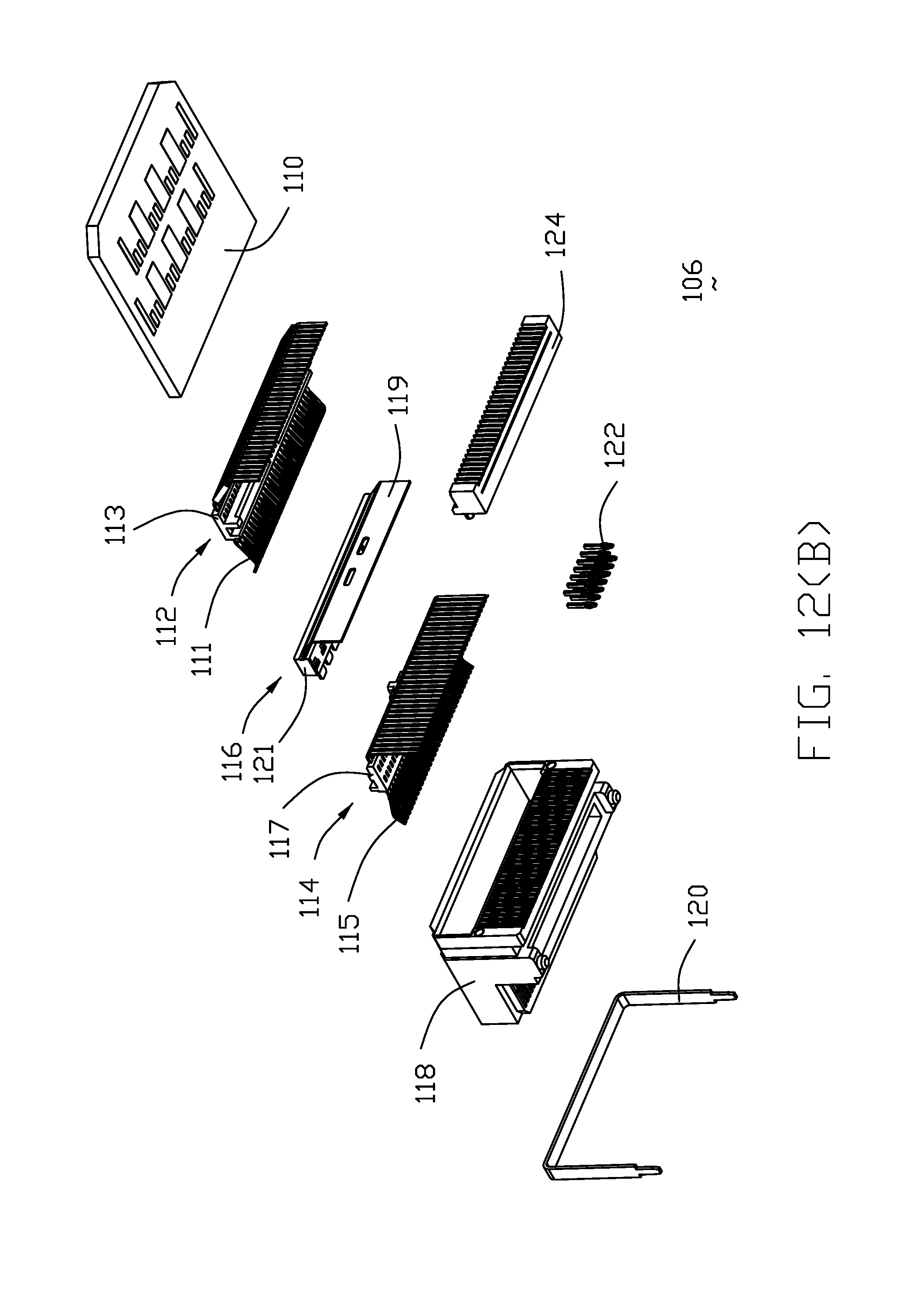
[0025] FIG. 12(A) is an exploded perspective view of the right angle receptacle connector directly attached to the adaptor cable of the second half of the electrical system of FIG. 11;
[0026] FIG. 12(B) is another perspective view of the right angle receptacle connector directly attached to the adaptor cable of the second half of the electrical system of FIG. 12(A);
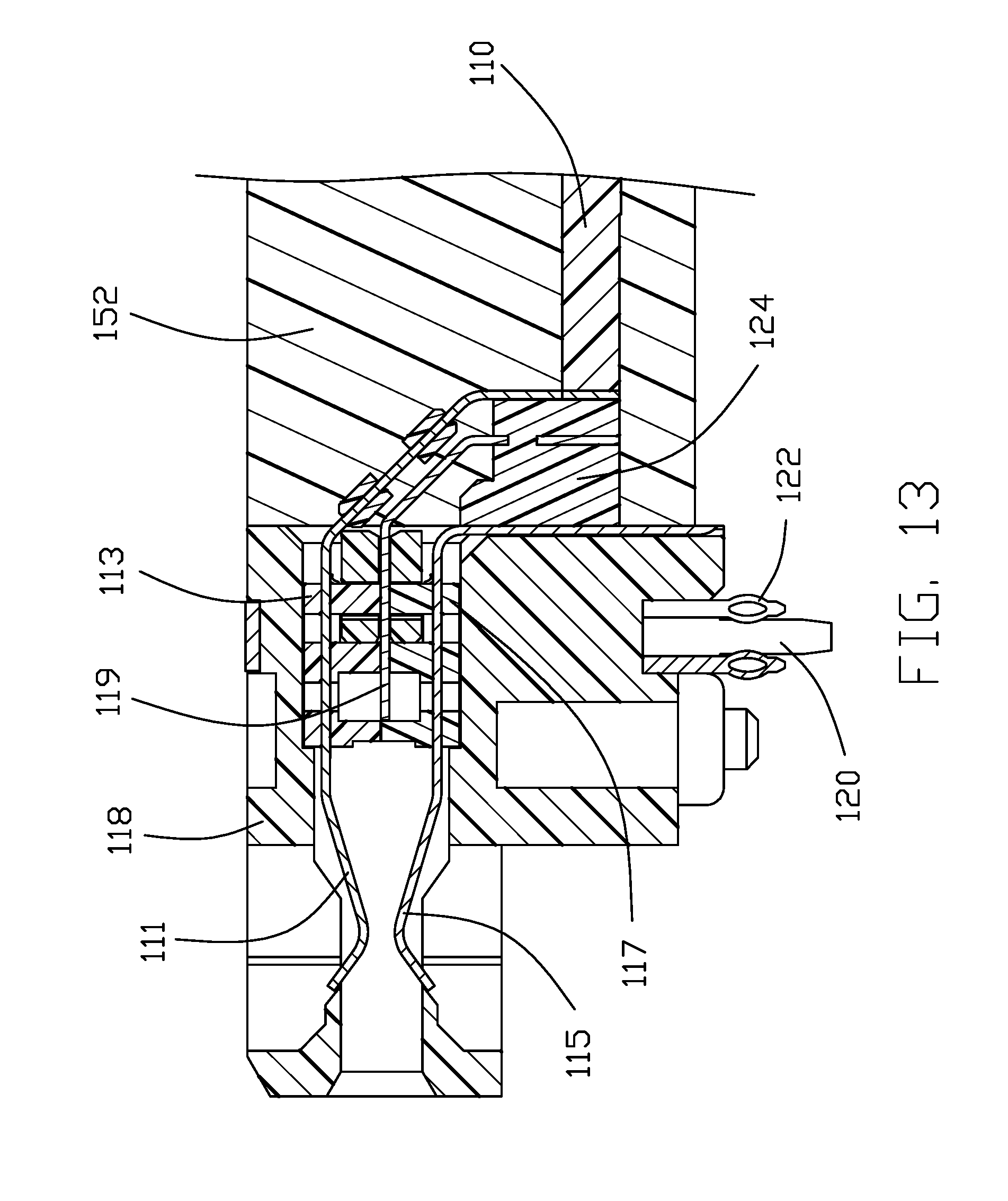
[0027] FIG. 13 is a cross-sectional view of the right angle receptacle connector directly attached to the adaptor cable of the second half of the electrical system of FIG. 12(A);
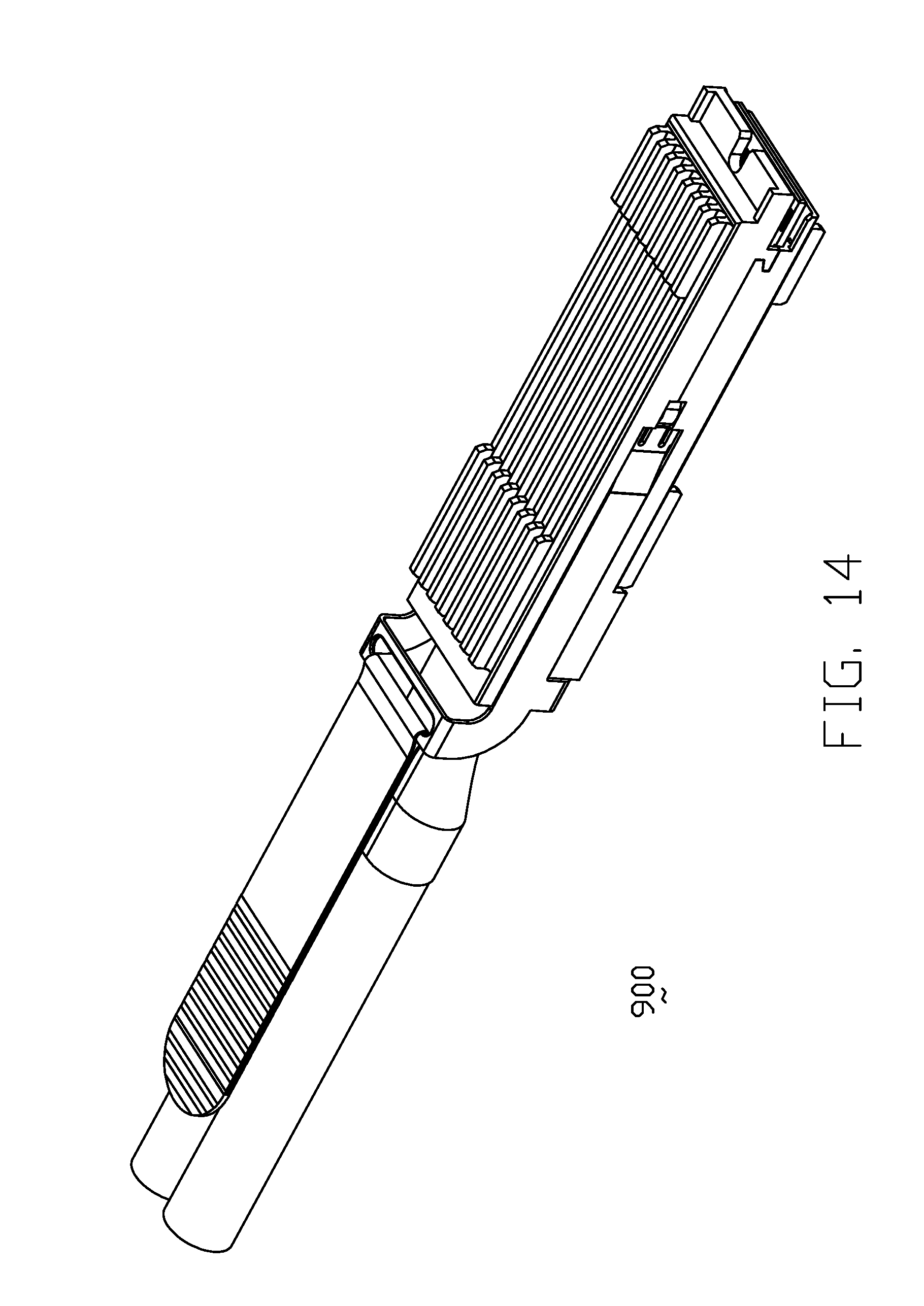
[0028] FIG. 14 is a perspective view of the FP5 pluggable module of the electrical system of FIG. 1(A);
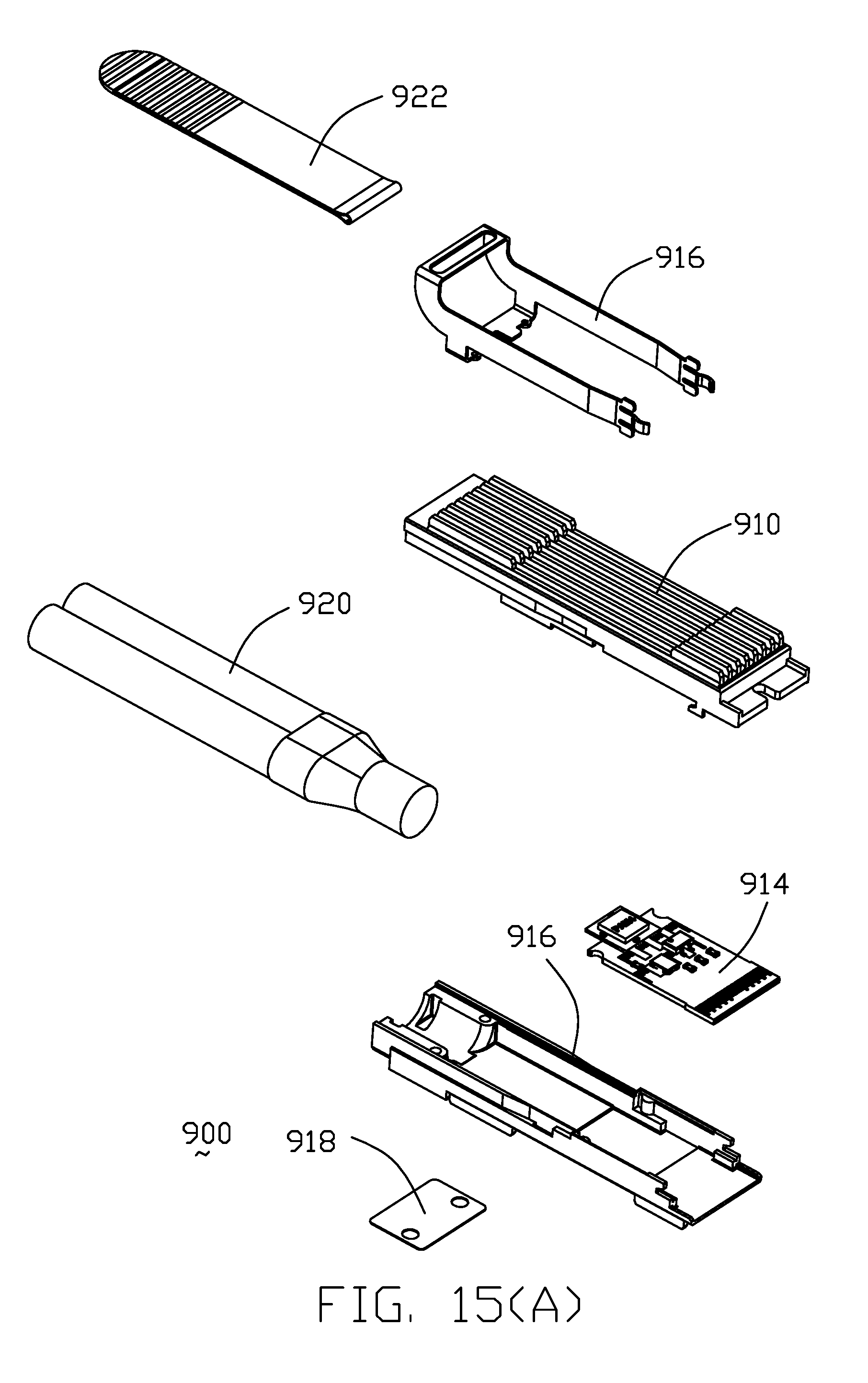
[0029] FIG. 15(A) is an exploded perspective view of the FP5 pluggable module of the electrical system of FIG. 14;
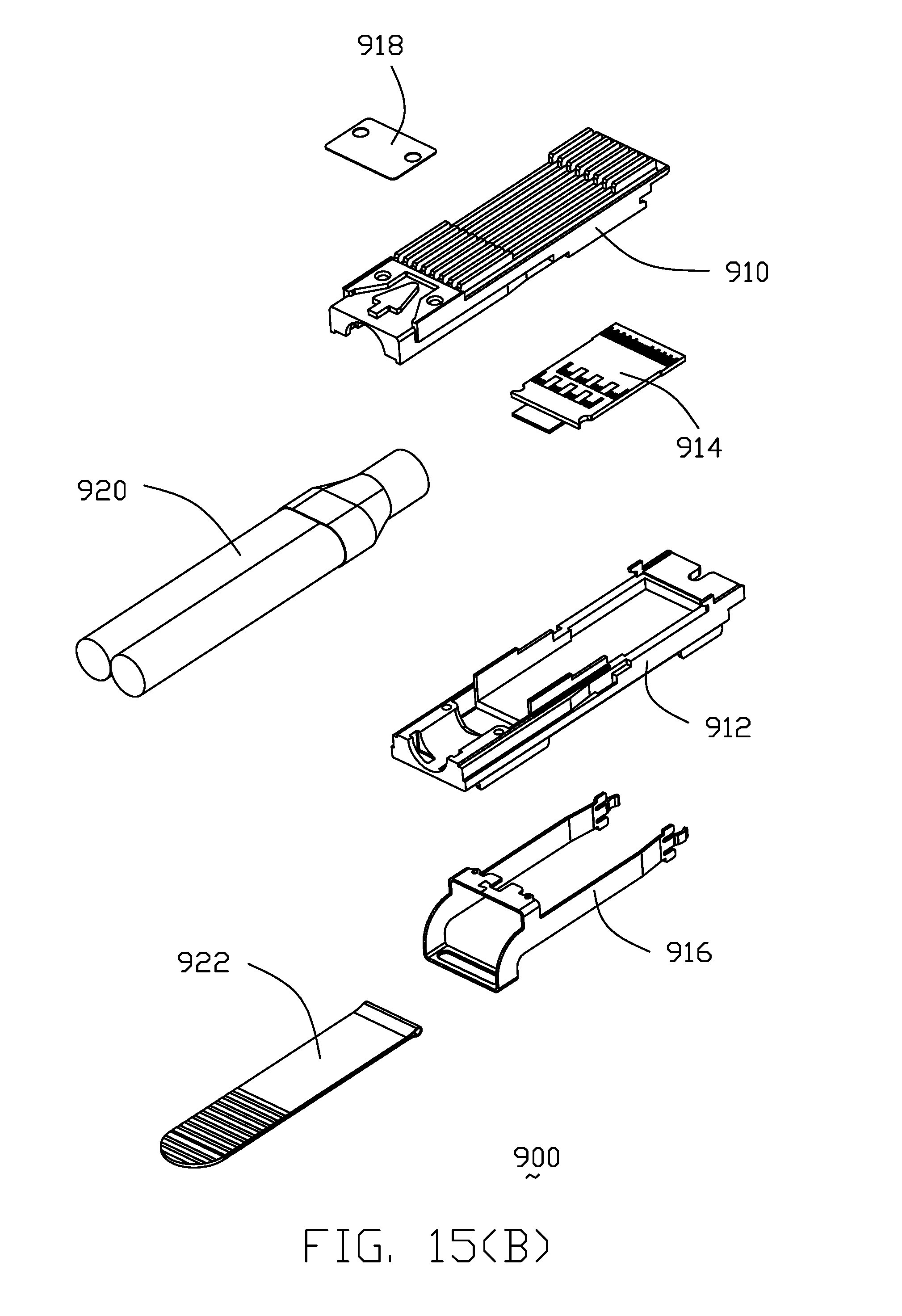
[0030] FIG. 15(B) is another exploded perspective view of the FP5 pluggable module of the electrical system of FIG. 14;
[0031] FIG. 16(A) is a perspective view of an electrical system according to a second embodiment of the invention using the stacked dual-sided QSFP-DD receptacle connector;
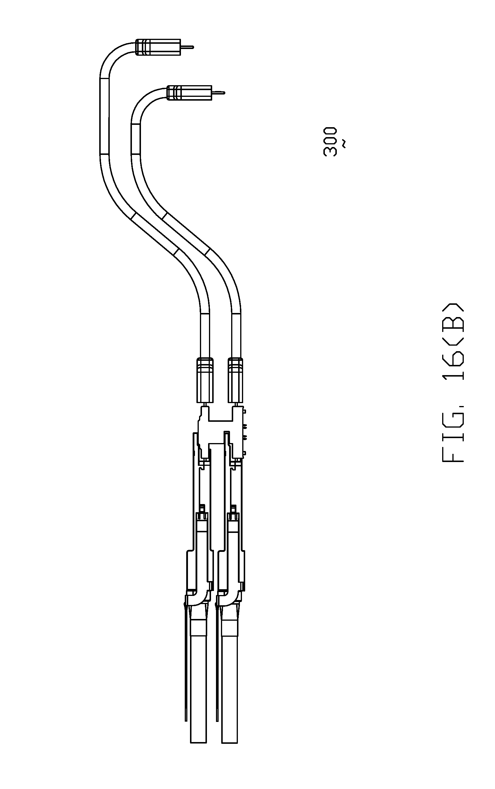
[0032] FIG. 16(B) is a side view of the electrical system of FIG. 16(A);
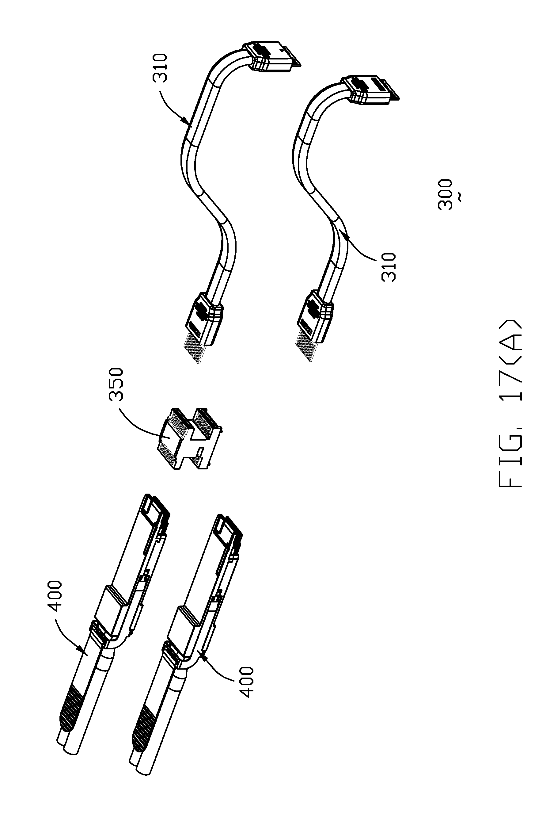
[0033] FIG. 17(A) is an exploded perspective view of the electrical system of FIG. 16(A);
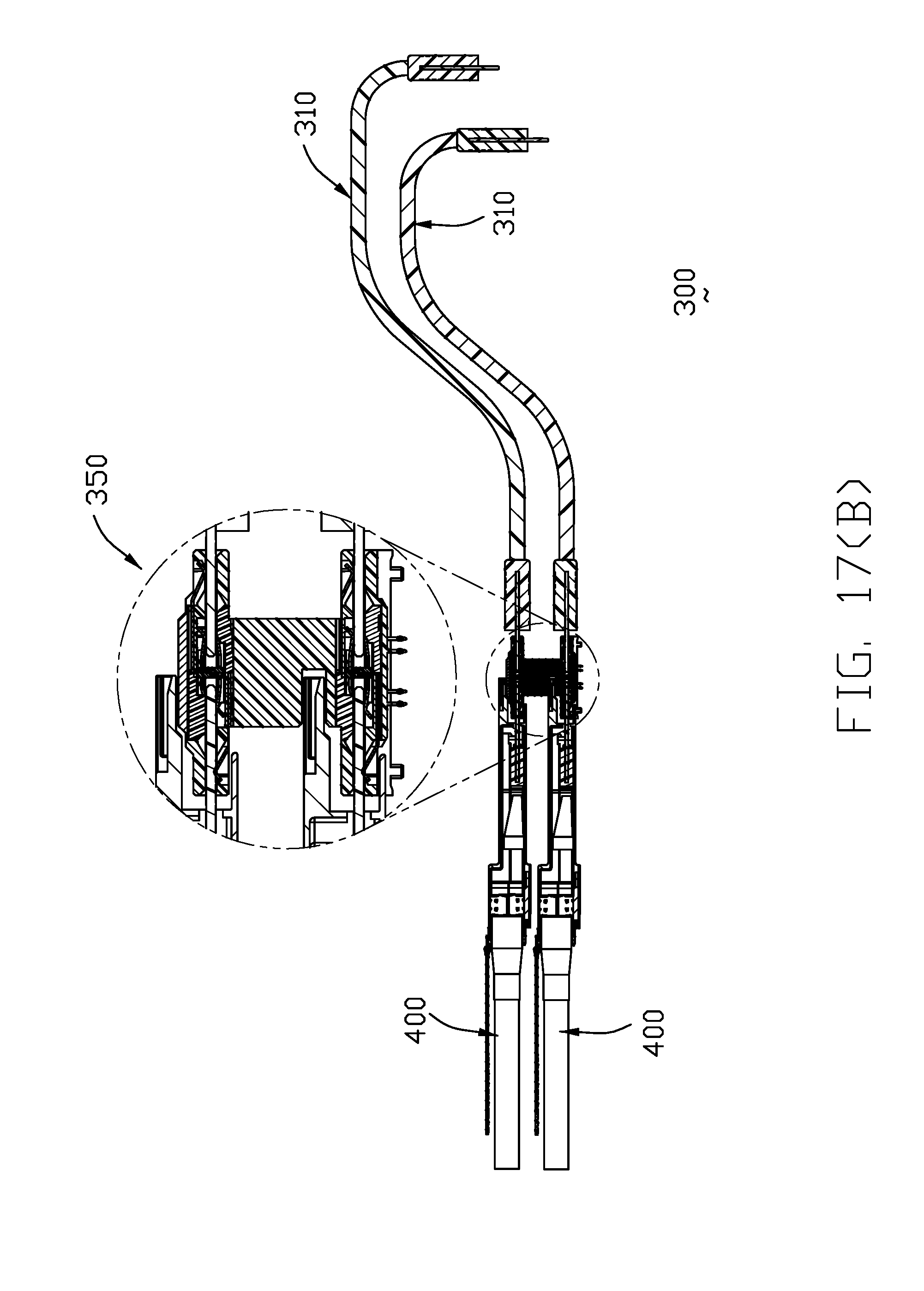
[0034] FIG. 17(B) is a cross-sectional view of the electrical system of FIG. 16(B);
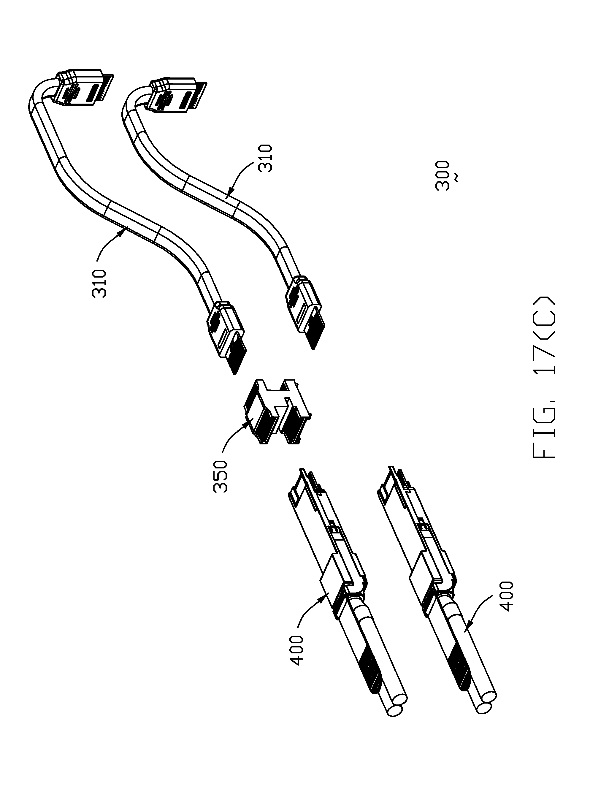
[0035] FIG. 17(C) is another exploded perspective view of the electrical system of FIG.17(A);
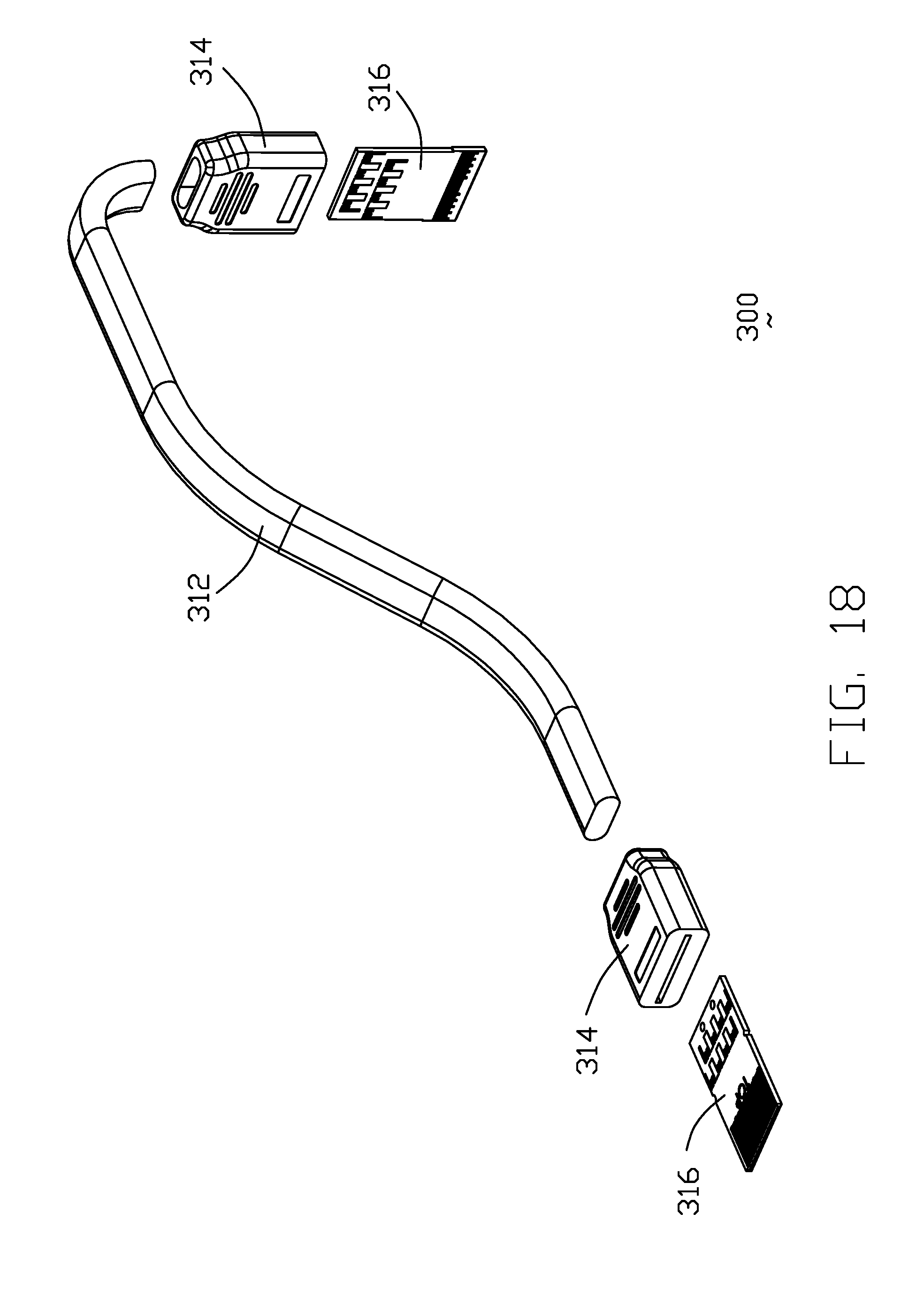
[0036] FIG. 18 is an exploded perspective view of the adaptor cable of the electrical system of FIG. 16(A);
[0037] FIG. 19 is a stacked dual-sided receptacle connector of the electrical system of FIG. 16(A);
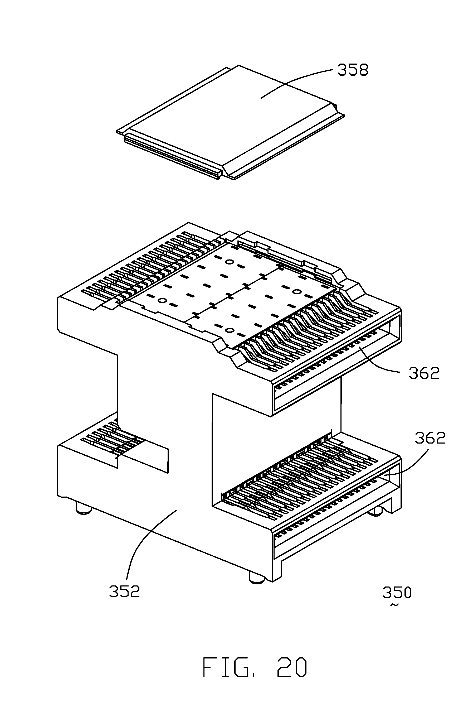
[0038] FIG. 20 is an exploded perspective view of the stacked dual-sided receptacle connector of the electrical system of FIG. 19;
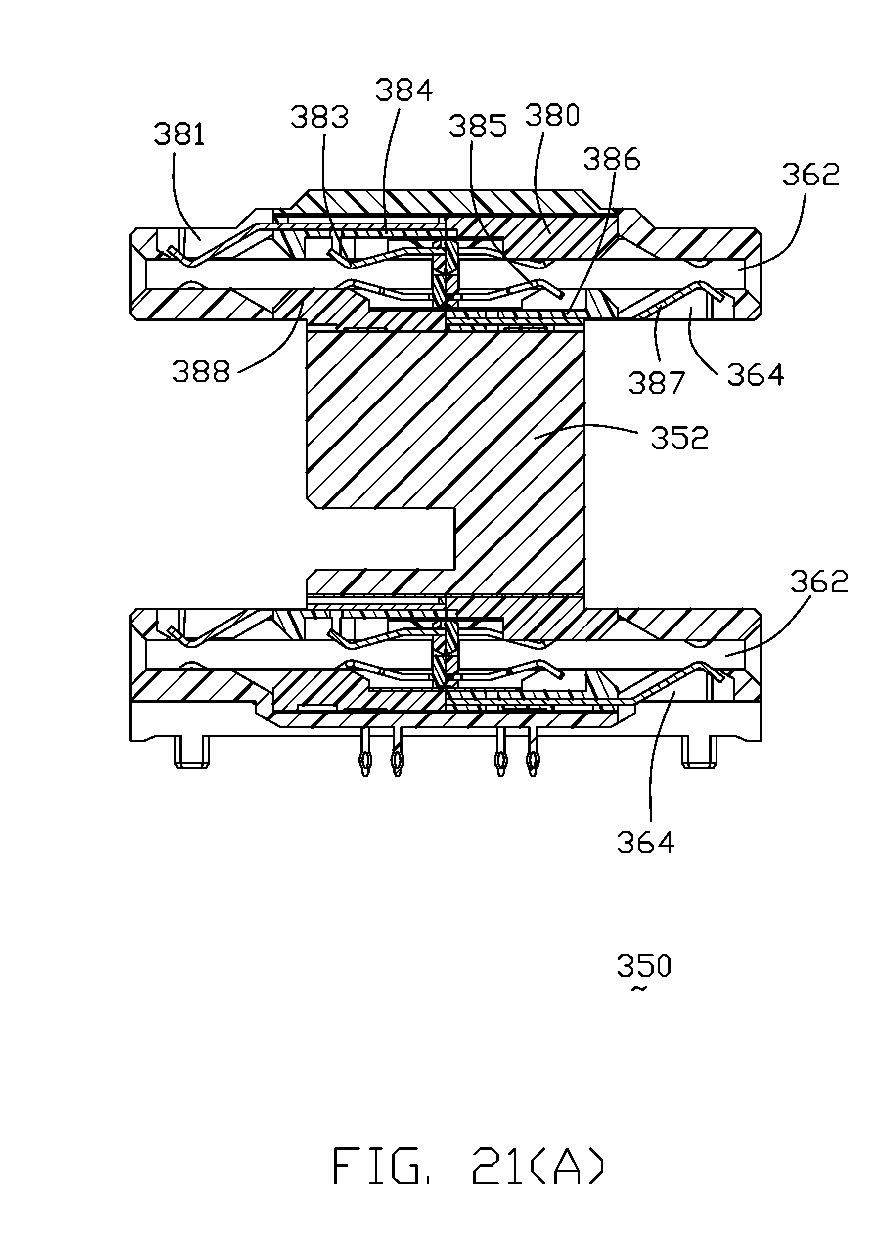
[0039] FIG. 21(A) is a cross-sectional view of the stacked dual-sided receptacle connector of the electrical system of FIG. 19;
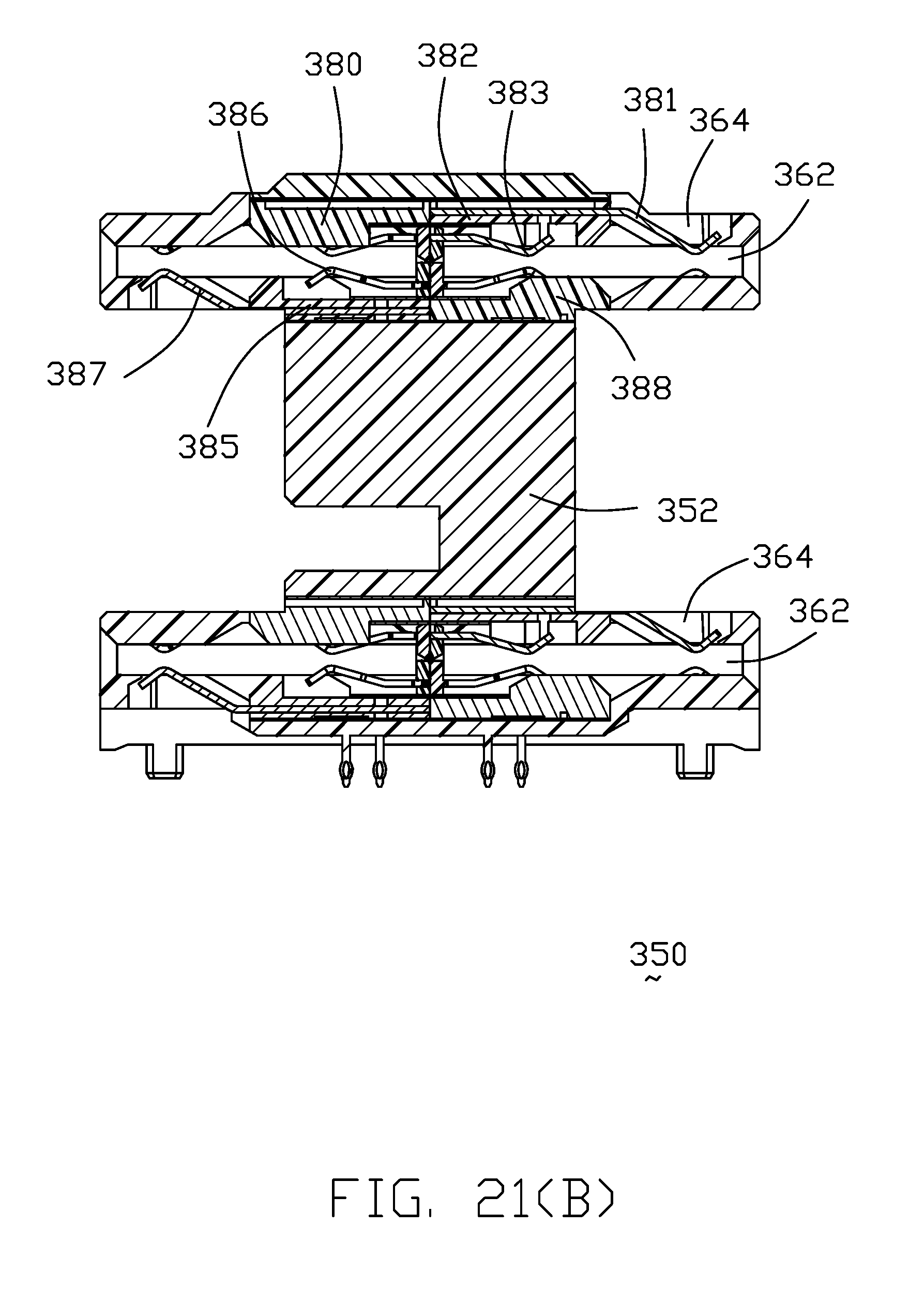
[0040] FIG. 21(B) is another cross-sectional view of the stacked dual-sided receptacle connector of the electrical system of FIG. 19;
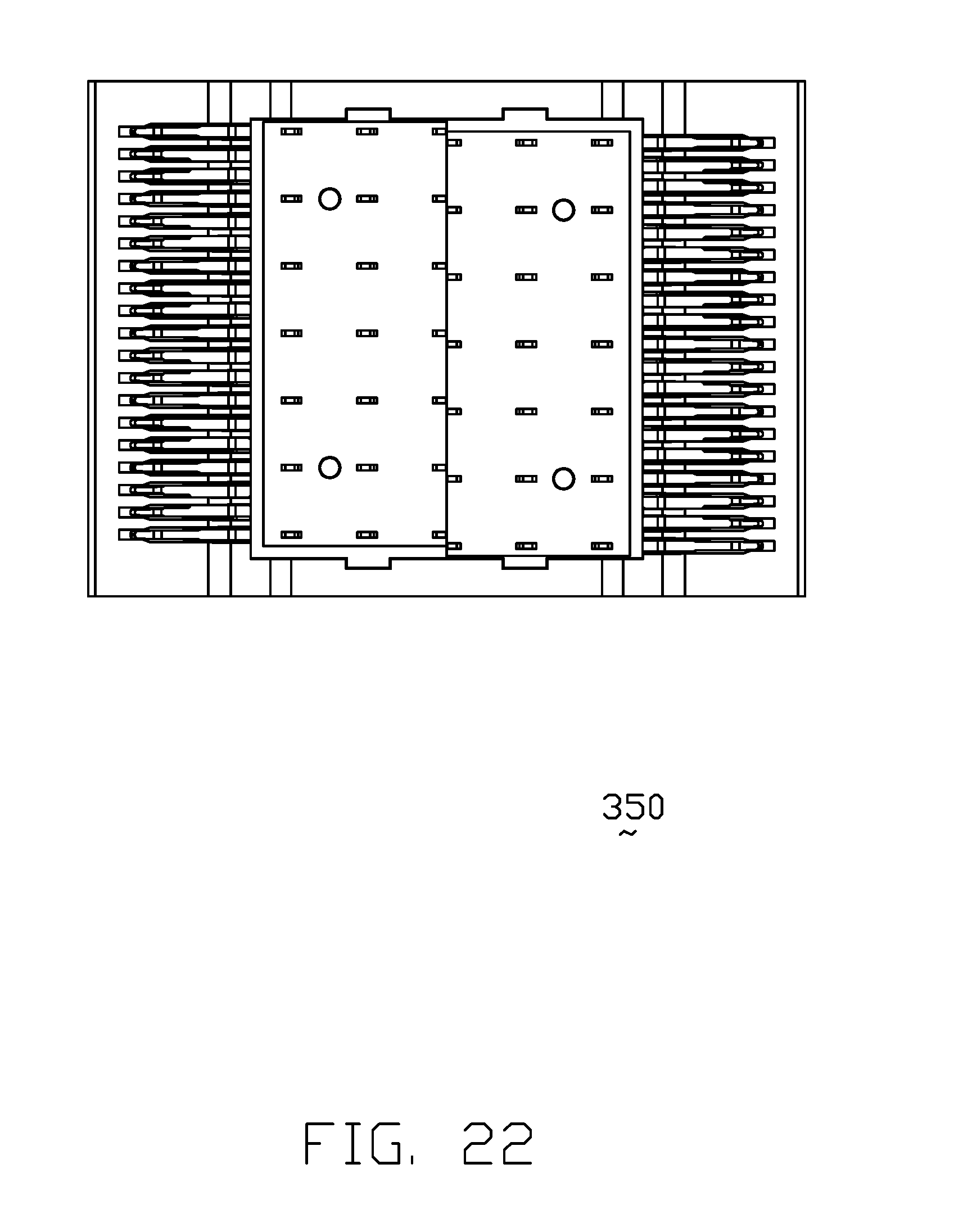
[0041] FIG. 22 is a top view of the stacked dual-sided receptacle connector of the electrical system of FIG. 19 by removing the top cover;
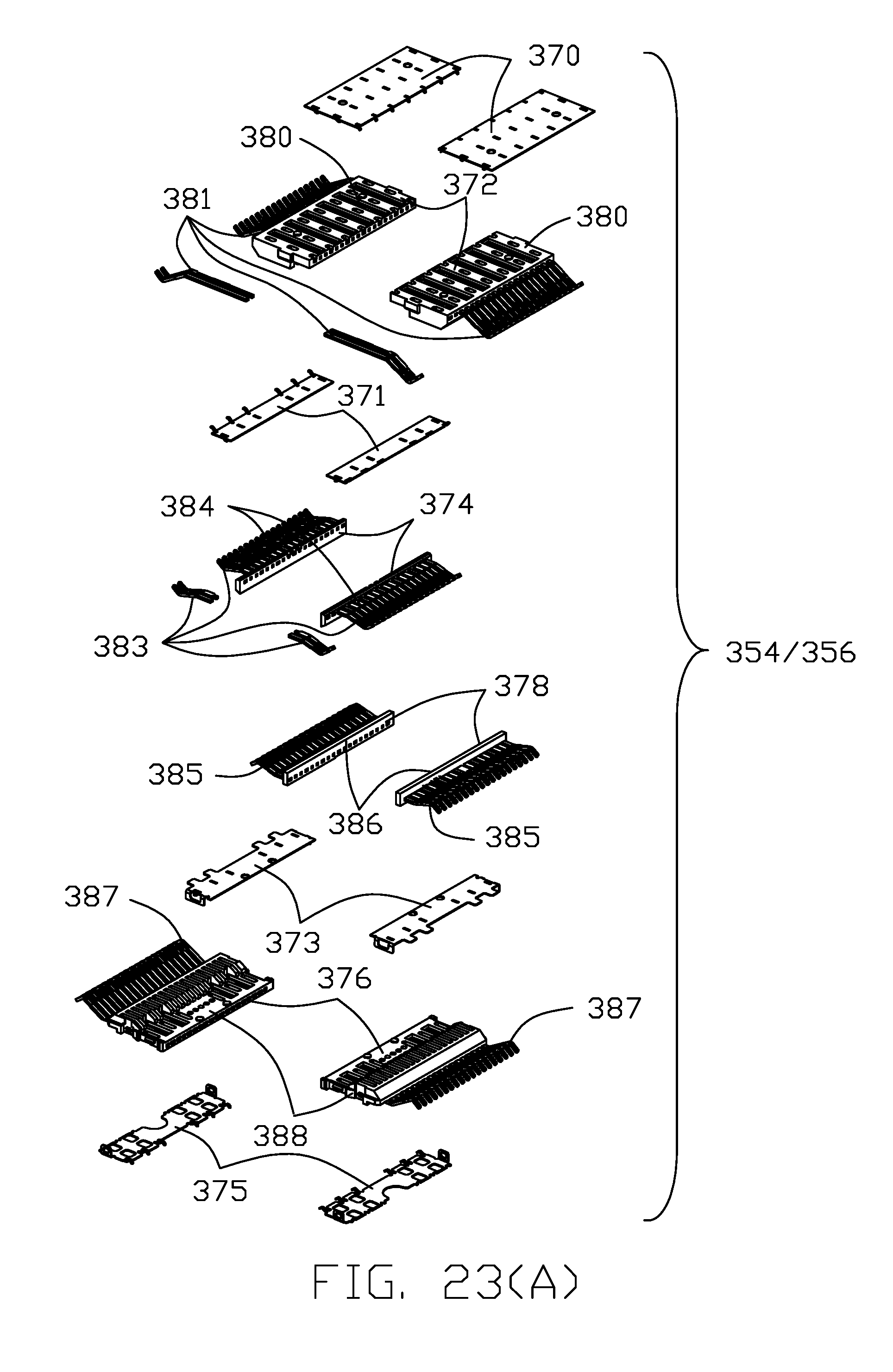
[0042] FIG. 23(A) is an exploded perspective view of the contact module of the stacked dual-sided receptacle connector of the electrical system of FIG. 19;
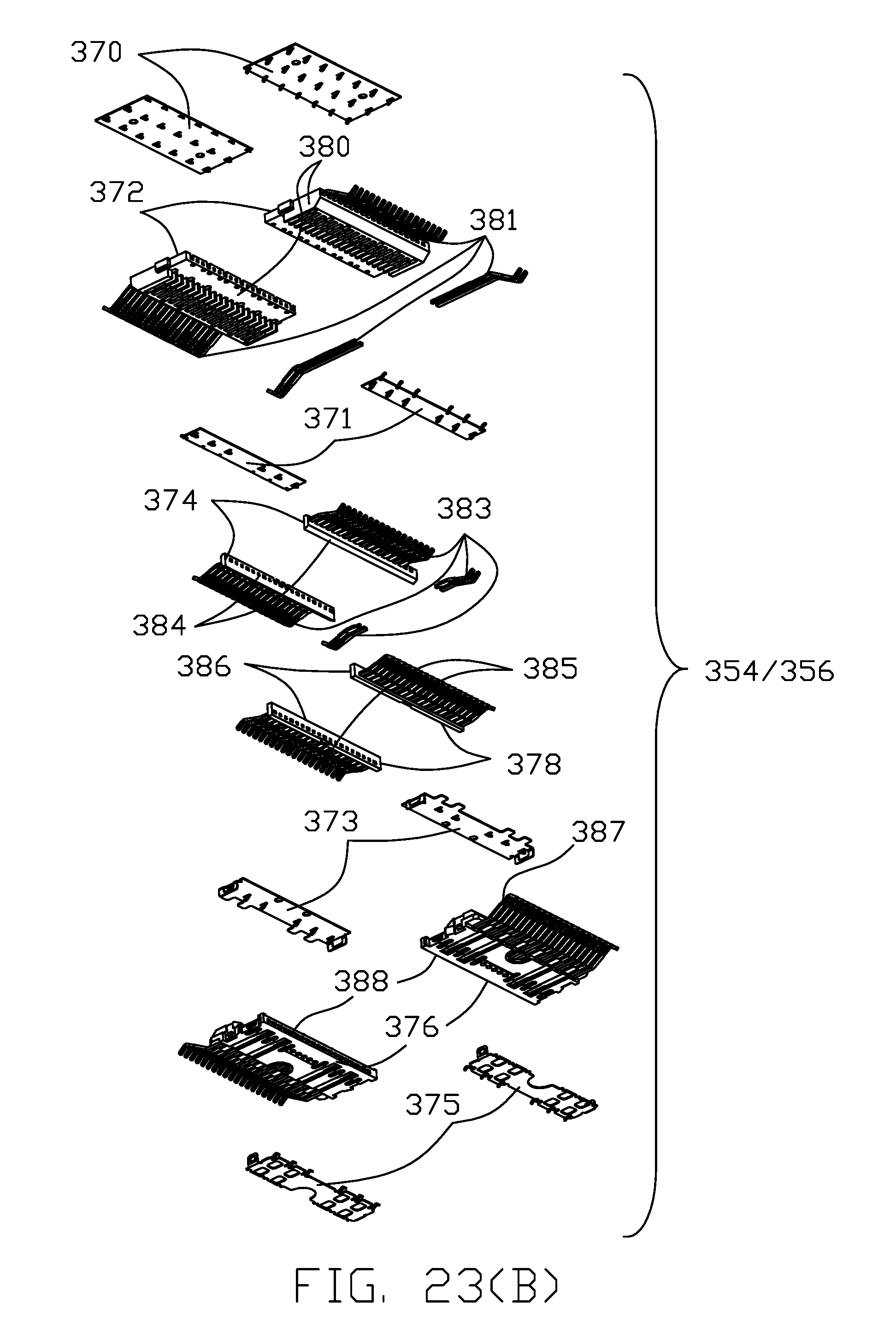
[0043] FIG. 23(B) is another exploded perspective view of the contact module of the stacked dual-sided receptacle connector of the electrical system of FIG. 23(A);
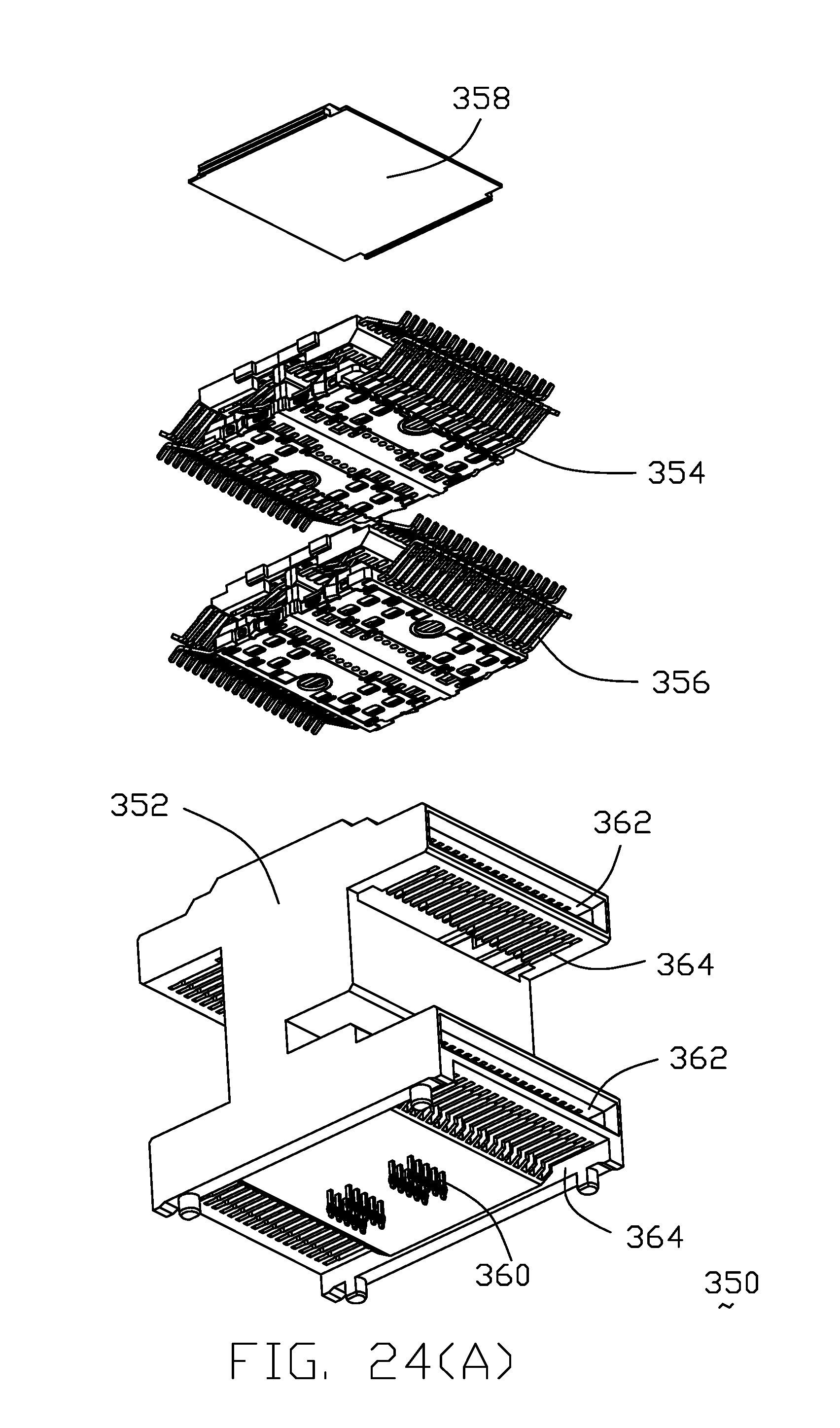
[0044] FIG. 24(A) is an exploded perspective view of the stacked dual-sided receptacle connector of the electrical system of FIG. 19;
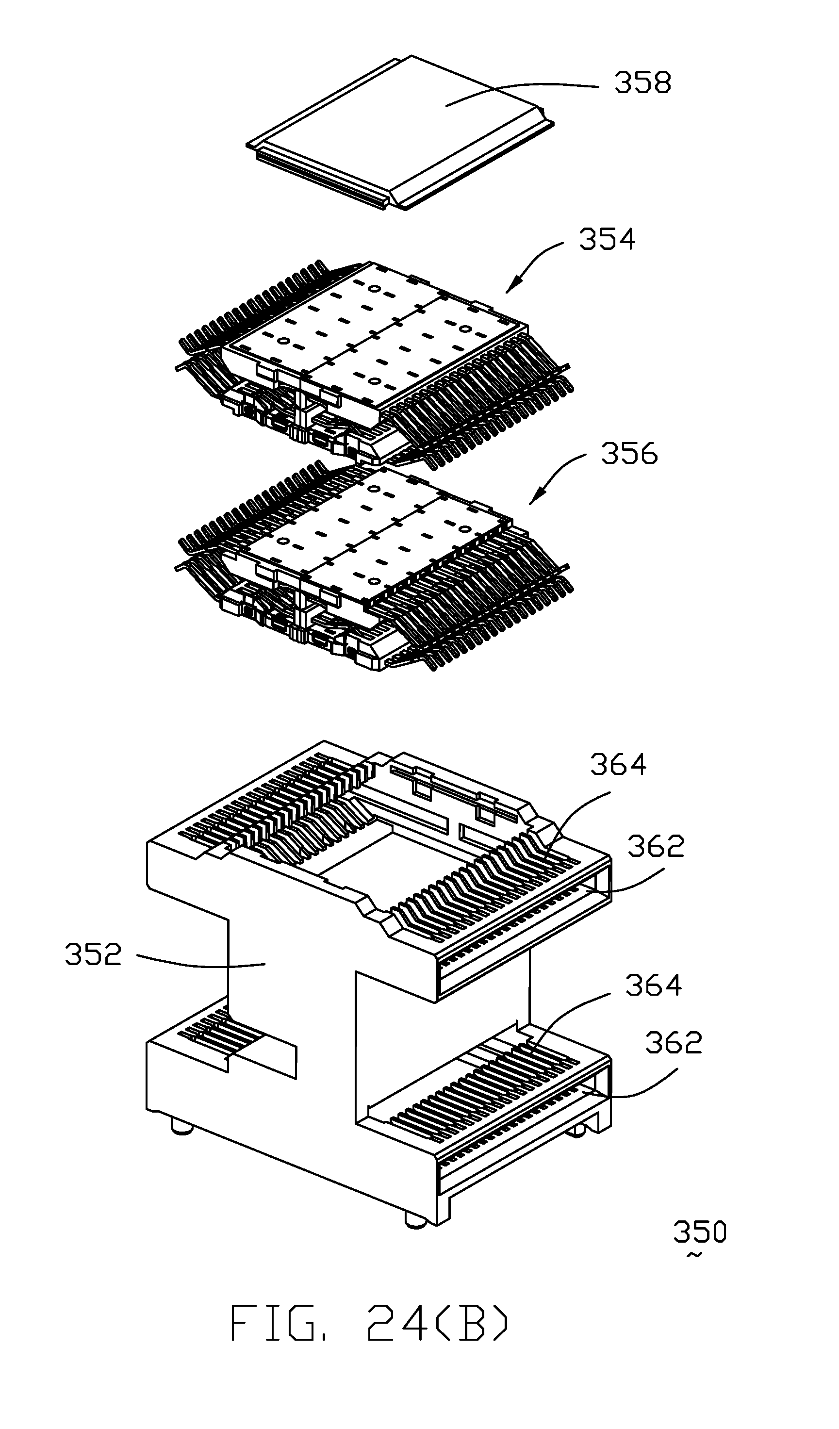
[0045] FIG. 24(B) is another exploded perspective view of the stacked dual-sided receptacle connector of the electrical system of FIG. 24(A);
[0046] FIG. 25 is a perspective view of a QSFP-DD pluggable module of the electrical system of FIG. 16(A);
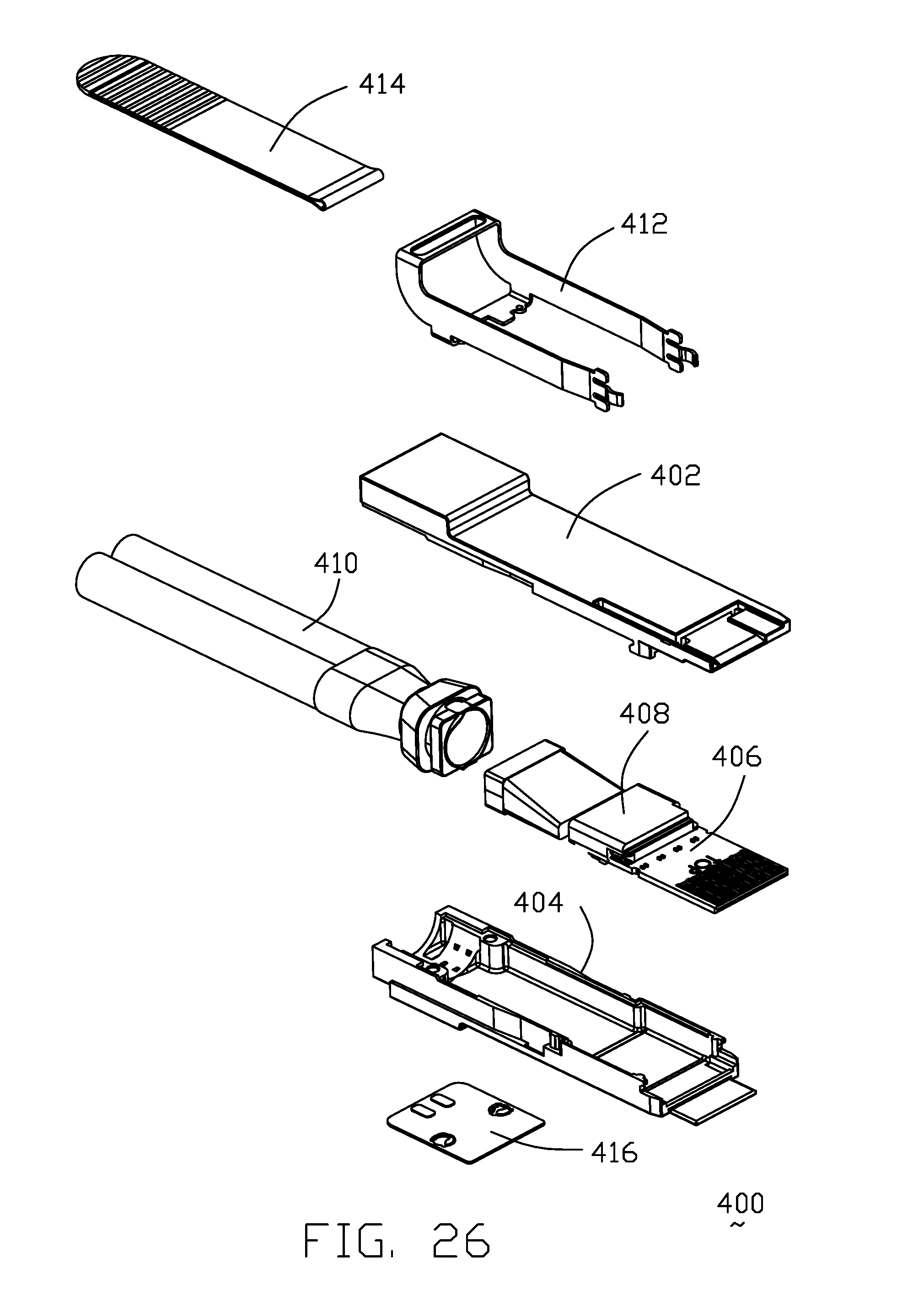
[0047] FIG. 26 is an exploded perspective view of the QSFP-DD pluggable module of the electrical system of FIG. 25;
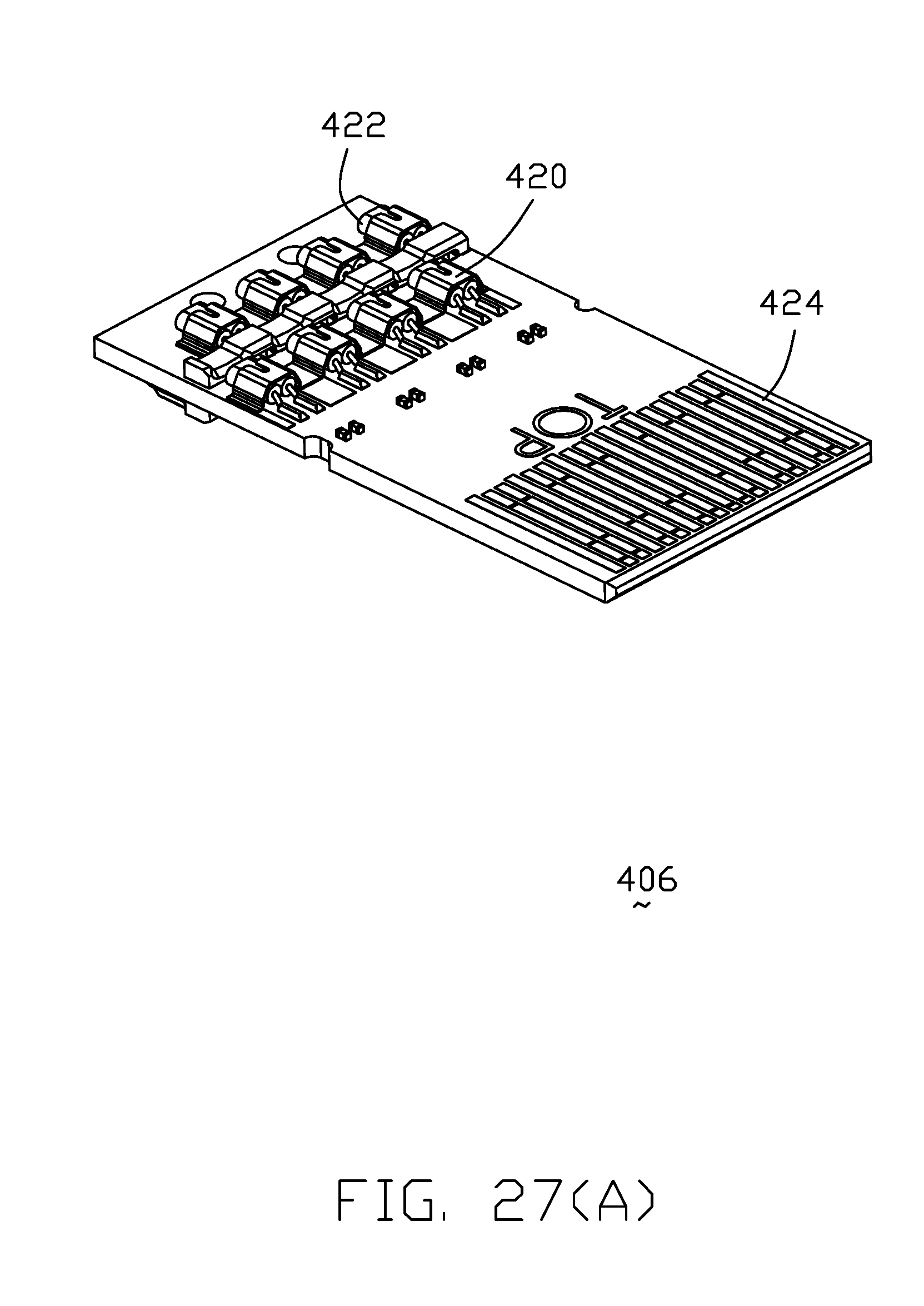
[0048] FIG. 27(A) is a top view of the paddle card of the QSFP-DD pluggable module of the electrical system of FIG. 25;
[0049] FIG. 27(B) is a bottom view of the paddle card of the QSFP-DD pluggable module of the electrical system of FIG. 25; and
DETAILED DESCRIPTION OF THE PREFERRED EMBODIMENT
[0050] Reference will now be made in detail to the preferred embodiment of the present invention. Referring to FIGS. 1(A) to 15(B), an electrical system includes a main board 1000 with a first half and a second half side by side arranged with each other in a transverse direction. The first half of the electrical system includes a first adaptor cable assembly 150 connected between a vertical FP5 receptacle connector 1010 and a first module insertion port 250. The second half of the electrical system includes a second adaptor cable assembly 100 connected between another vertical FP5 receptacle connector 1010 and a second module insertion port 200. In this embodiment, the first module insertion port 250 is to receive the corresponding QSFP-DD pluggable module 950 while the second module insertion port 200 is to receive the corresponding FP5 pluggable module 900.
[0051] As shown in FIGS. 4(A) and 4(B), the second module insertion port 200 is essentially a hollow metallic cage formed by the main part 202 and the bottom part 204 while as shown in FIGS. 7(A) and 7(B), the first module insertion port 250 includes a hollow metallic cage 256 with a heat sink 254 attached thereon via the clip 252 and communicatively facing an interior space of the cage 256 through the opening (not labeled) for removing the heat from the inserted pluggable module 950. A metallic gasket 258 is attached upon the cage 256 around the front opening (not labeled), and a dual-sided receptacle connector or the so-called extender or adaptor 260 are located around a rear end region of the cage 256.
[0052] As shown in FIGS. 8(A) and 8(B), the dual-sided receptacle connector 260 includes an insulative housing 262, a contact module 270 is assembled therein, and an insulative cover 264 is attached thereon to retain the contact module 270 in position. The contact module 270 essentially includes the upper inner part 272, the upper outer part 271, the lower inner part 277 and the lower outer part 279 assembled together wherein each part has its own contacts 275 and both the upper inner part 272 and the lower inner part 277 are disposed around the inner port of the housing 262, and both the upper outer part 271 and the lower outer part 279 are disposed around the outer port of the housing 262. The contact 275 has the corresponding mating portion disposed in the corresponding inner/outer port of the housing 262 so as to be deemed as the inner/outer mating portion. Understandably, the contacts 275 of lower inner part 277 and those of the lower outer part 279 are electrically connected, and the contacts 275 of the upper inner part 272 and those of the upper outer part 271 are electrically connected as well so as to transmit the signals from the corresponding QSFP-DD pluggable module 950 to the first adaptor cable assembly 150 and vice versa. In this embodiment, additional conductive connecting legs/tails 266 for mounting to the printed circuit board 1000, are associated with the dual-sided receptacle connector 260 and mechanically and electrically connected to the corresponding contacts 275 around the center region wherein such contacts 275 are for optional low speed signal transmission. In other words, as mentioned above the high speed transmission is done by the cable 310 disclosed in another embodiment while the low speed transmission is done by the printed circuit board without involvement with the cable 310 disclosed in another embodiment. The details of the contact module 270 will be illustrated later with reference to FIGS. 23(A)-24(B). Also, the mating among the QSFP-DD pluggable module 950, the one floor type dual-sided receptacle connector 260 and the first adaptor cable assembly 150 will be illustrated later with reference to FIGS. 16(A)-18.
[0053] As shown in FIGS. 9-10, the vertical receptacle connector 1010 is essentially of an FP5 interface and includes an insulative housing 1012 with a contact module 1014 therein. The contact module 1014 includes a first part 1018 composed of the contacts 1017 integrally formed within the first insulator 1019, a second part 1020 composed of the contacts 1021 integrally formed within the second insulator 1023, and a third part 1016 sandwiched between the first part 1018 and the second part 1020 and composed of the shielding pieces 1013 integrally formed within a third insulator 1015.
[0054] As shown in FIGS. 11-13, the second adaptor cable assembly 100 includes a cable 102 with an inner connector 104 at the inner end, and an outer connector 106 at the outer end. The inner connector 104 is essentially of a FP5 plug board interface for mating with the vertical receptacle connector 1010. The outer connector 106 includes an insulative housing 118 with a contact module (not labeled) therein. The contact module includes a first part 112 composed of the contacts 113 integrally formed within the first insulator 111, a second part 114 composed of the contacts 115 integrally formed within the second insulator 117, and a third part 116 sandwiched between the first part 112 and the second part 114 and composed of a metallic shielding piece 119 integrally formed within the third insulator 121. A spacer 124 is assembled to the housing 118 for regulating the contact tails (not labeled). A plurality of conductive connecting legs/legs 122 mechanically and electrically are connected to the corresponding contacts 113 and 115 around the center region and mounted to the main board 1000 for optional low speed signal transmission through the main board rather than through the adaptor cable assembly 100. A paddle card 110 are mechanically and electrically connected to the corresponding contacts 113 and 115 and protectively enclosed within the connector 106. A mounting clip 120 secures the connector 106 upon the main board 1000. Understandably, the outer connector 106 is mated with the FP5 pluggable module 900 which is inserted into the second module insertion port 200.
[0055] As shown in FIGS. 14-15(B), the FP5 pluggable module 900 includes a metallic top cover 910 with heat sink structure thereon and a metallic bottom cover 912 commonly forming an interior receiving space to receive a printed circuit board assembly 914 therein. A releasing bar 916 activated by a pull tape 922 is positioned upon the top cover 910 and the bottom cover 912. A cable 920 is connected to the printed circuit board assembly 914. A metallic cover 918 is attached upon the bottom cover 912.
[0056] As shown in FIGS. 16(A)-27(B), an electrical system 300 according to another embodiment using the stacked dual-sided receptacle connector therewith. As shown in FIG. 17(A)-17(C), the electrical system 300 includes a pair of QSFP-DD pluggable modules 400 electrically connected to a pair of adaptor cables assemblies 310 via a stacked dual-sided receptacle connector or extender or adaptor 350. Notably, the QSFP-DD pluggable module 400 is mated with an outer (side) port of the dual-sided receptacle connector 350, and the adaptor cable assembly 310 is mated with an inner (side) port of the dual-sided receptacle connector 350. As shown in FIG. 18, the adaptor cable assembly 310 includes a cable 312 with at an inner end, an inner connector composed of a mating board 316, which is essentially of an FP5 plug board interface for mating with the vertical receptacle connector 1010, retained in the insulative holder 314, and at an outer end, an outer connector composed of a mating board 316, which is essentially of a QSFP-DD plug board interface for being received within the inner (side) port of the dual-sided receptacle connector 350, retained by the insulative holder 314.
[0057] As shown in FIGS. 19-24(B), the stacked dual-sided receptacle connector 350 includes an insulative housing 352 with corresponding cavities (not labeled) to receive the corresponding upper contact module 354 and lower contact module 356, respectively. The insulative housing 352 forms opposite inner receiving slot and outer receiving slot 362 in both of the lower floor/level and upper floor/level. Each contact module 354/356 includes a pair of inner/outer large upper parts 372 associated with a pair of inner/outer small upper parts 374 with a pair of inner/outer upper grounding sheets 371 therebetween, and a pair of inner/outer large lower parts 376 associated with a pair of inner/outer small lower parts 378 with a pair of inner/outer lower grounding sheets 373 therebetween. The large upper part 372 is composed of the large upper insulator 380 and the large upper contacts 381, the small upper part 374 is composed of the small upper insulator 384 and small upper contacts 383, the large lower part 376 is composed of the large lower insulator 388 and the large lower contacts 387, and the small lower part 378 is composed of the small lower insulator 386 and the small lower contacts 385. Similar to the first embodiment, the (inner) large upper contacts 381 and the (outer) large upper contacts 381 are electrically connected, and the small upper contacts 383, the large lower contacts 387 and the small lower contact 385 are as well in the same pattern so as to transmit the signals between the external QSFP pluggable module 400 and the internal adaptor cable assembly 310. Understandably, in an alternate embodiment, the inner large upper contact 381 and the corresponding outer large upper contact can be unified together as one piece, and the corresponding small upper contacts, 383, the large lower contacts 387 and the small lower contacts 385 can be done as well.
[0058] Notably, during mating, the mating board of either the QSFP-DD pluggable module 400 is sandwiched between the associated (outer) large upper part 372/small upper part 374 and the associated (outer) large lower part 376/small lower part 378 in the vertical direction. Similarly, the mating board of the adaptor cable assembly 310 is sandwiched between the associated (inner) large upper part 372/small upper part 374 and the associated (inner) large lower part 376/small lower part 378 in the vertical direction.
[0059] The top metallic top cover 370 is attached upon the upper face of the upper contact module 354, and the metallic bottom cover 375 is attached upon the bottom face of the lower contact module 356. The insulative housing 352 further forms a plurality of passageways 364 for allowing deflection of the corresponding contacts. Similar to the first embodiment, an insulative top cover 358 is attached upon the top face of the housing 352, and the conductive connecting legs/tails 360 are further electrically connected to the corresponding contacts around the center region of the dual-sided receptacle connector 350 for optional low speed signal transmission.
[0060] As shown in FIGS. 25-27(B), similar to the FP5 pluggable module 900 disclosed in the first embodiment, the QSFP-DD pluggable module 400 includes a metallic top cover 402, a metallic bottom cover 404 commonly defining an interior space to receive a paddle card 406 and the associated inner insulator 408. A releasing bar 412 and a pull tape 414 are attached upon the top cover 402 and the bottom cover 404. A cable 410 is connected to the paddle card 406, and a metallic cover 416 is attached upon the bottom cover 404. The paddle card 406 includes a front mating pads 424, and a plurality of securing bracket 420 to hold the respective wire 422 of the cable 410 in position.
* * * * *
D00000
D00001
D00002
D00003
D00004
D00005
D00006
D00007
D00008
D00009
D00010
D00011
D00012
D00013

D00014

D00015

D00016
D00017
D00018
D00019
D00020
D00021
D00022
D00023

D00024
D00025
D00026
D00027
D00028
D00029

D00030
D00031
D00032
D00033
D00034
D00035
D00036
D00037
D00038

D00039
D00040
D00041

XML
uspto.report is an independent third-party trademark research tool that is not affiliated, endorsed, or sponsored by the United States Patent and Trademark Office (USPTO) or any other governmental organization. The information provided by uspto.report is based on publicly available data at the time of writing and is intended for informational purposes only.
While we strive to provide accurate and up-to-date information, we do not guarantee the accuracy, completeness, reliability, or suitability of the information displayed on this site. The use of this site is at your own risk. Any reliance you place on such information is therefore strictly at your own risk.
All official trademark data, including owner information, should be verified by visiting the official USPTO website at www.uspto.gov. This site is not intended to replace professional legal advice and should not be used as a substitute for consulting with a legal professional who is knowledgeable about trademark law.